1. Introduction
Titanium and titanium alloys have been selected as structural parts and members with high specific strength [
1] and high biocompatibility [
2]. Various material designs have broadened their application field not only for airplanes, automotive, and implants [
3] but also for glass frames, surgical knives, acetabular cups [
4], and anti-bacterial parts [
5]. These intensive demands from industries and medicals are often hindered by the difficulty of workability in metal forming. As stated in [
6], titanium and titanium alloys were identified as hard-to-work materials in practical metal forming. In deep-drawing, the drawing ratio became far below 2.0 and invariant to die-material selection [
7]. High frictional state was preserved on the contact interface between the protective coating and titanium works [
8]. Microstructure [
9], texture evolution [
9,
10], and fatigue performance [
11] were also investigated in the literature. As the reduction in thickness in forging must be minimized, the annealing process was intermediately included in the routine operation and cleansing and polishing after every step of forging were indispensable to continue the forging operation [
12,
13]. In each step of forging, the reduction in thickness is limited less than 20%. The near-net forging of titanium alloy products from wire feedstock must be designed on the innovative die-material selection with a self-lubricating mechanism [
14]. To overcome this difficulty in the forging situation, the self-lubrication process by metal matrix nanocomposites has attracted attention [
15]. The free carbon and carbon thin films were also useful to reduce the tool wear in unlubricated conditions [
16,
17].
As studied in [
18,
19,
20,
21,
22], the isolated free carbon from the carbon-supersaturated (CS) punch formed a carbon-based tribofilm onto the contact interface between punch and work to significantly reduce the friction and galling wear. The friction coefficient was estimated to be less than 0.1, by using the experimental correlation between the bulging deformation of upset work and the friction coefficient [
18,
19]. No adhesion of titanium fragments and oxide debris particles onto the die surface was observed through all the forging process [
18,
19,
20,
21,
22]. This galling-free forging with the use of carbon-supersaturated dies is preferable to the near-net forging of pure titanium and titanium alloy works. However, the near-net forging performance of titanium and titanium alloy feedstock, for complex-shaped products, has not been clarified in detail when using CS dies.
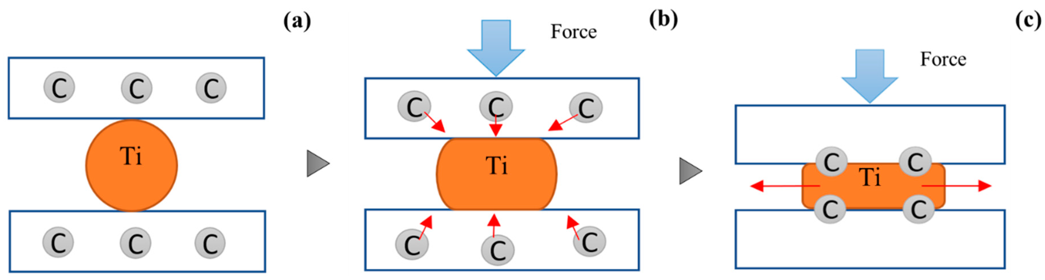
The present study aims at the description and analysis of the solid lubrication effect on the near-net forging to complex geometries. The CS-SKD11 punch and die are prepared by a low-temperature plasma-carburizing system. As illustrated in
Figure 1a, the carbon solute is present as an interstitial atom in the die matrix. Due to the stress gradient induced by the reactive force applied to the die surface, these carbon solutes diffuse toward the true contact interface and form a tribofilm on it, as depicted in
Figure 1b,c. This in situ solid lubrication during the near-net forging significantly lowers the friction and galling wear and reduces the work hardening. These free-carbon tribofilms are in situ formed onto the true contact interfaces. The near-net forging is performed under the minimum quantity solid lubrication by these in situ formed tribofilms.
2. Materials and Methods
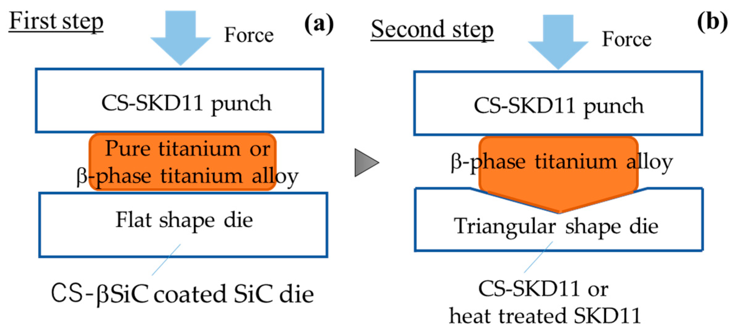
The experiment was performed in two steps, as shown in
Figure 2.
Figure 2a shows the upsetting experiment, where the CS-SKD11 punch and CS-βSiC-coated SiC die were utilized for CNC forging. The CS-SKD11 punch was only prepared by using the low-temperature plasma carburizing system. The pure titanium wires and β-phase titanium alloy wires were upset by 50% reduction in thickness only in a single shot. The friction coefficient was rationally estimated to be 0.05 by the inverse analysis with aid of three-dimensional finite element model. The hardness mapping on the cross-section of upset work proves that work-hardening process was significantly suppressed to be free from shear localization. Microstructural analysis was used to investigate the tribofilm, formed on the contact interface, and to demonstrate that the low friction and low work hardening was driven by the solid lubrication of tribofilm. In the second forging experiment, as shown in
Figure 2b, the CS-SKD11 punch and die were used to make near-net shaping of the circular wire to a triangular bar, also in a single shot. The normal heat-treated (HT) SKD11 die was used as a reference to describe the effect of free-carbon tribofilm on the forging with the use of CS-SKD11 die. The β-phase titanium alloy wire was upset by 50% reduction in thickness only in a single shot. The upsetting and near-net forging were utilized to describe the workability of β-titanium alloy wires by increasing the reduction in thickness.
SEM (Scanning Electron Microscopy)–EDX (Energy Dispersive X-ray spectroscopy) and Raman spectroscopy were used to analyze the tribofilm formation from the carbon-supersaturated dies. The inverse analysis with aid of 3D finite element model was employed to estimate the friction coefficient on the interface. The hardness mapping on the cross-section of forged titanium works was used to describe the work-hardening behavior.
2.1. Low Temperature Plasma Carburizing Process
High-density RF (radio frequency)—DC (direct current) plasma carburation process was utilized to make carbon supersaturation into SKD11 punch and die. As shown in
Figure 3, the punch and die were fixed into the hollow cathode in the chamber before evacuation down to 0.1 Pa. Under the argon atmosphere, this unit was heated up to 673 K (or 400 °C) and presputtered by the DC plasma, under an argon and hydrogen mixture gas, with the flow rate of 160 mL/min for argon and 20 mL/min for hydrogen, for 1.8 ks. Methane gas with the flow rate of 20 mL/min was introduced to make carburizing for 14.4 ks. After carburizing, the experiment unit was cooled down to RT under the nitrogen gas atmosphere.
2.2. CNC-Forging Process
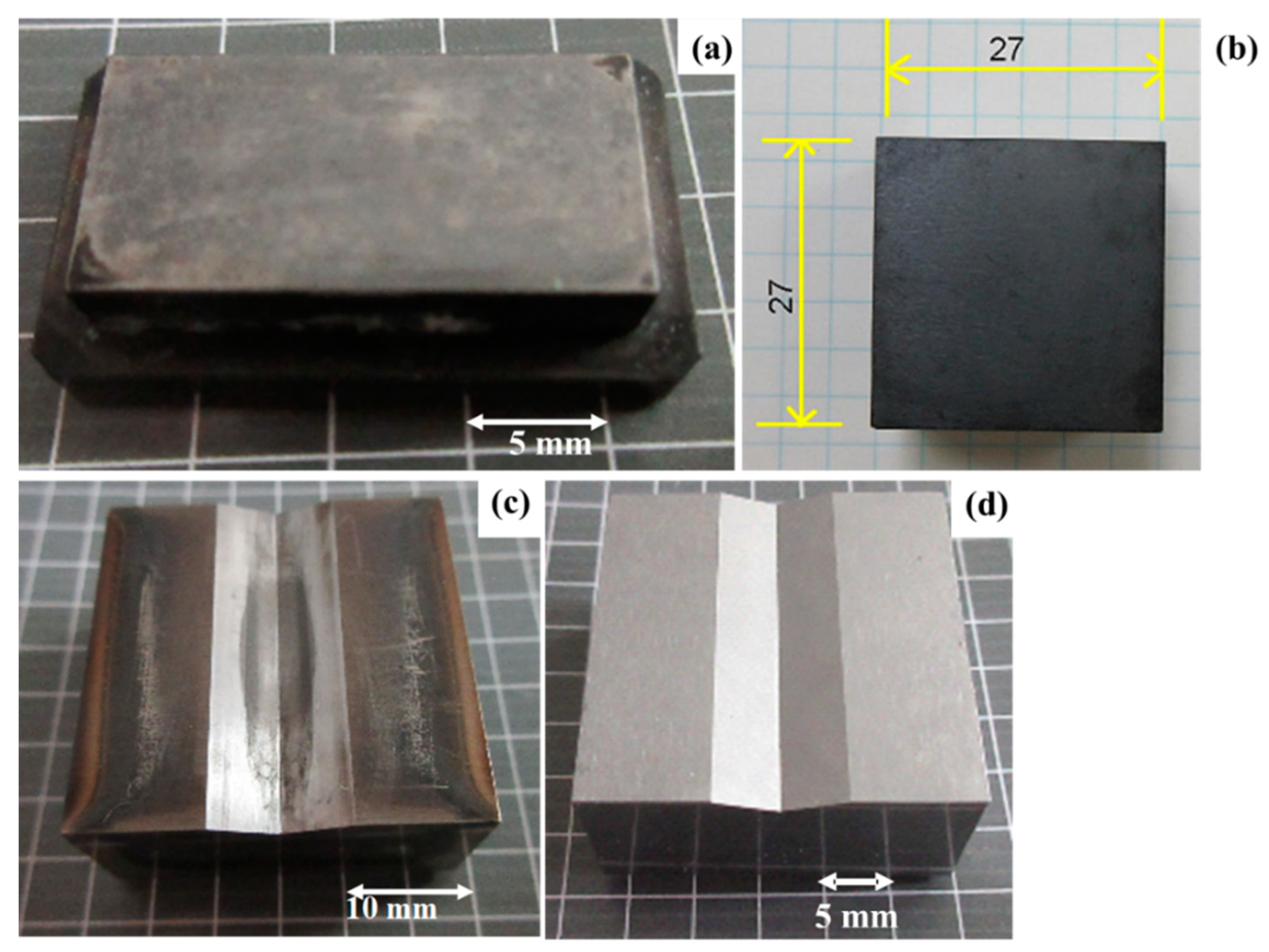
The CNC-forging system was utilized in the following two forging experiments. In the upsetting experiment, the CS-SKD11 punch in
Figure 4a and the CS-βSiC-coated SiC die in
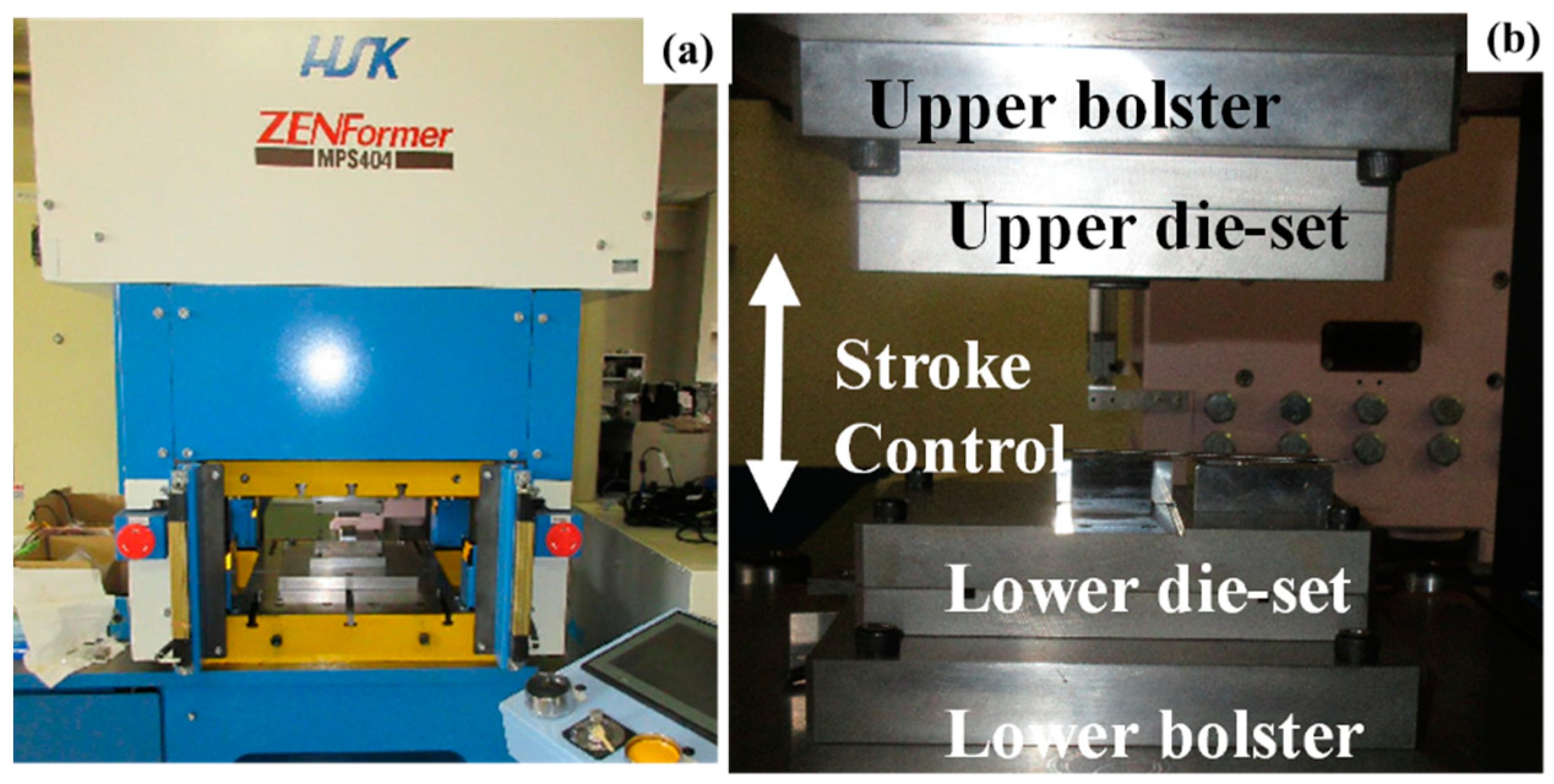
Figure 4b were fixed into the upper and lower cassette die sets, respectively. The die sets were cemented to upper and lower bolsters of the CNC-forging system in
Figure 5. The reduction in thickness was varied by stroke controlling the upper bolster. As reported in previous studies [
13,
14,
15,
16], CS-βSiC-coated SiC dies are wrought as a galling-free die both in cold and hot forming conditions. After this experiment, the die set was exchanged with a new die set for near-net forging. The CS-SKD11 punch and die in
Figure 4a,c were fixed and used under similar stroke control. A triangular groove with A width of 10.00 mm and A depth of 1.5 mm was machined ground into these two dies. The tolerance of triangular groove depth was set at ±0.05 mm.
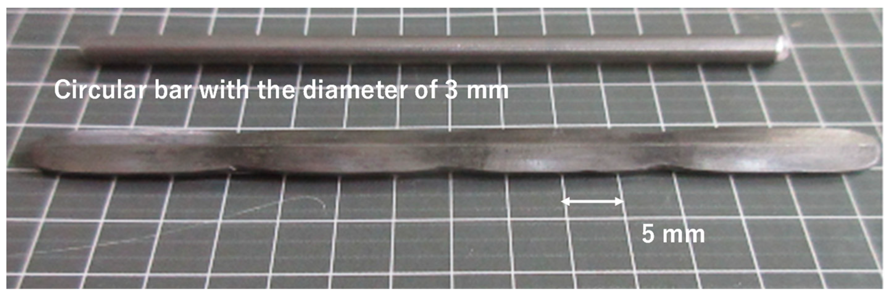
2.3. Work Materials
A pure titanium wire with industrial grade I and the β-phase titanium alloy wire was employed as a work for forging experiments. Their diameter was 3.0 mm, and their normal length was 10.0 mm. The chemical composition of pure titanium wires consists of hydrogen by 0.0012 mass%, oxygen by 0.097 mass%, nitrogen by 0.007 mass%, iron by 0.042 mass%, carbon by 0.007 mass%, and titanium for balance. The chemical compositions of β-titanium wires were listed in the following; e.g., 0.01 mass% carbon, 3.1 mass% aluminum, 14.6 mass% vanadium, 0.21 mass% iron, 3.2 mass% tin, 2.9 mass% chromium, 0.01 mass% nitrogen, 1300 ppm oxygen, 40 ppm hydrogen, and titanium in balance.
After [
23], the pure titanium has HCP (hexagonal close-packed) structure, while the β-phase titanium has BCC (body-center cubic) structure. This crystallographic structure difference reflects on the workability in cold forging processes. In general, BCC-structured metals have more slipping planes than HCP-structured ones. Then, the plastic flow capacity is expected to be enhanced in forging the BCC-structured metals and alloys.
2.4. Inverse Analysis to Estimate the Friction Coefficient on the Interface
Deform-3D was employed as a three-dimensional finite element model to estimate the friction coefficient on the interface by the inverse analysis. The forged wire width (Wo) and contact interface width (Wi) were selected as a common processing parameter for both the upsetting experiment and the finite element analysis (FEA). In FEA, the friction coefficient was virtually varied to deduce the regression curve of Wi (μ) − Wo (μ). If μ ~ 0.0, Wi ~ Wo; while Wi << Wo, if μ > > 1.0. Provided that WiE and WoE were experimentally measured in upsetting at the specified reduction in thickness, a true frictional coefficient μ0 could be determined by minimization of |Wi (μ) − WiE| and |Wo (μ) − WoE|.
2.5. Hardness Mapping
The forged specimen at each reduction in thickness was cut by EDM (Electrical Discharging Machining) and embedded in resin at 453 K (or 180 °C). The cross section of the embedded specimens was polished by the abrasive paper from # 80 to # 4000 and finally buffed by using the alumina abrasive particles with the size of 0.3 µm. The hardness tester (HM-100; Mitsutoyo, Co., Ltd.; Kanagawa, Japan) was employed to measure the hardness distribution on the cross section of the specimens. The applied load for this hardness testing was held constant by 1 N for 10 s.
2.6. Materials Characterization
SEM-EDX (HITACHI SU-70 and EDAX Pegasus; Tokyo, Japan) was used to analyze the tribofilm, which formed onto the contact interface. EDX measurement was performed under the acceleration voltage of 15 kV, and the scanning rate of 0.96 ms. Raman spectroscopy (NRS-7100; Nihonbunkou, Co., Ltd.; Tokyo Japan) was also employed to characterize the carbon structure in the tribofilm.
3. Experimental Results
The single-shot upsetting was performed up to 50% in reduction in thickness, to describe the galling-free forging behavior of pure titanium wire by using the CS-SKD11 punch and the CS-βSiC-coated SiC die. SEM–EDX analysis was utilized to investigate the formation of tribofilm on the contact interface between the CS-SKD11 punch and the titanium work. Single-shot near-net forging was employed to describe the shaping process from the original circular wire to the triangular bar. The work hardening was significantly suppressed by using the CS-SKD11 punch and die.
3.1. Single Shot Upsetting with 50% Reduction in Thickness
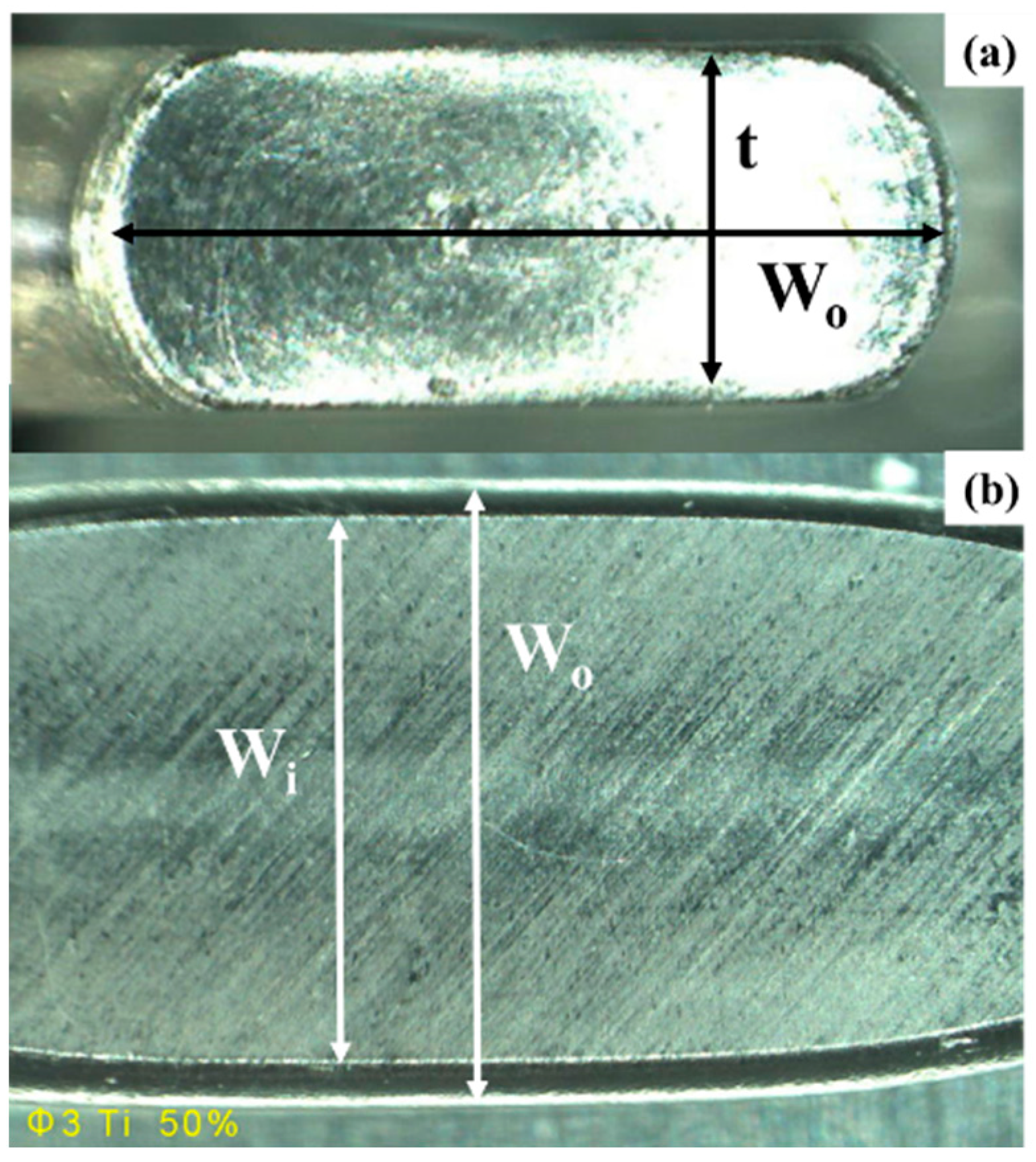
A pure titanium wire with the diameter of 3.0 mm was upset in a single shot down to the reduction in thickness I by 50%, without lubricating materials and oils at RT. As depicted in
Figure 6, the original thickness was halved to t = 1.5 mm. The wire width (Wo) increased from 3.0 mm to 4.8 mm, while the contact interface width (Wi) also increased from 0.0 mm to 4.0 mm. Less bulging deformation than measured in the normal upsetting suggests that the friction coefficient on the contact interface is preserved, to be sufficiently low to drive the flattening metal flow in
Figure 6.
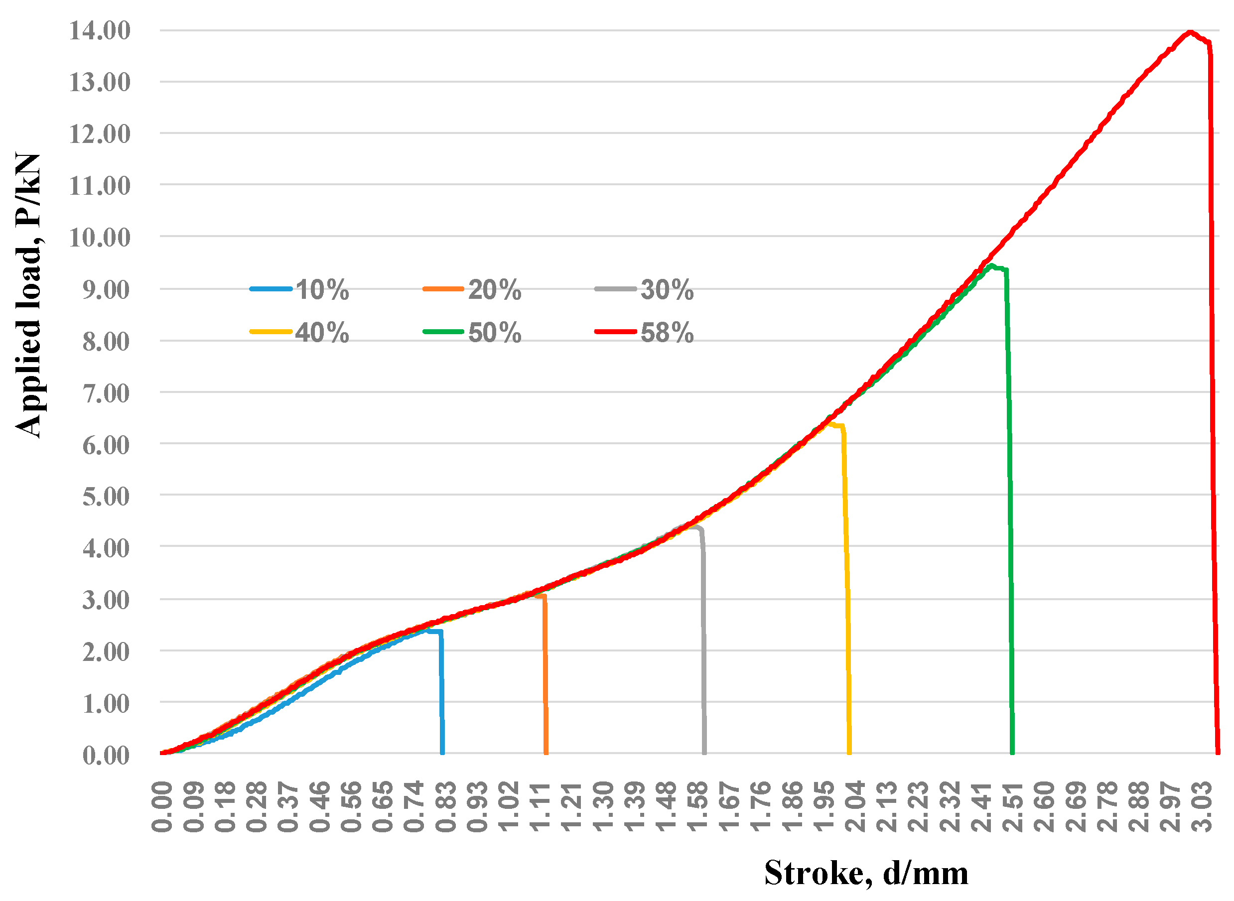
The load cell was embedded into the lower die set, and the load-to-stroke relationship was measured for upsetting to each reduction in thickness by r = 10%, 20%, 30%, 40%, 50%, and 58%, respectively. As shown in
Figure 7, the whole relationships are edited into one master curve between the load (P) and the stroke (d). When r < 10%, the circular wire is compressed, so that P increases linearly with increasing d. When 10% < r < 30%, P also increases linearly with d; P increases, since the contact area increases by the flattening of the work wire. For r > 30%, P increases exponentially with d. This suggests that the work hardening is suppressed up to 30% in reduction.
Let us measure the contact interface area (A = Wi × Li) at each r and estimate the normal stress IσN (r) = P/A). The contact area width (Wi) was determined by the average of measured Wis, and the contact area length (Li) was also calculated by the average of measured Lis. Since σN (10%) = 310 MPa, σN (20%) = 370 MPa, and σN (30%) = 340 MPa, P increases linearly, but the normal stress is nearly constant. This reveals that work hardening is suppressed to sustain the uniform stress state. Since σN (50%) = 440 MPa, the work hardening takes place with the flattening deformation of the wires.
A hardness mapping technique was employed to describe the work-hardening behavior of pure titanium and β-titanium specimens during the upsetting, as shown above. As stated in [
24], the hardness mapping is effective to analyze the local plastic flow in the work materials during metal forming.
Figure 8a depicts the hardness map on the cross section of upset pure titanium wire at r = 50%. At the vicinity near the wire-side surfaces, the work makes a bulging deformation, so that no hardening takes place. Except for the hardest spots where 255 HV < H < 270 HV, most of the work cross section has uniform hardness, where 225 HV < H < 255 HV. This uniform hardness profile is much exaggerated when upsetting the β-titanium wire down to 50%. As shown in
Figure 8b, the hardness is nearly constant around 225~255 HV in almost all the wire cross sections. This uniformity in hardness mapping demonstrates that no plastic localization occurs in the upsetting process with the use of the CS punch. To be discussed later, this is much different from the normal upsetting processes with shear localization, which finally induces the fatal fracture of work in compression.
The suppression of work hardening, and a lack of plastic localization of the titanium and titanium alloy works during upsetting, has a close relationship to the frictional state on the contact interface. When the contact interface has much higher friction coefficient than unity, the stress concentrates at the center of work, so that the work is thought to be fractured in half, as stated in [
25]. On the other hand, the work flattens and bulges with the reduction in thickness without stress concentration, when the friction coefficient is nearly zero or fully lubricated on the contact interface, as stated in [
26].
The inverse analysis, with the aid of a three-dimensional finite element model, was employed to estimate the friction coefficient (μ
0) on the contact interface. In the inverse analysis, μ
0 is determined to minimize the |W
i (μ) − W
iE| and |W
o (μ) − W
oE| on the regression curve of W
i (μ) − W
o (μ) for the experimentally measured W
iE and W
oE at r = 50%. Since W
iE = 3.918 mm and W
oE = 4.594 mm, μ
0 was estimated to be 0.05. To certify this estimate, the equivalent strain distribution at r = 50% was calculated by FEA, provided that μ = μ
0 = 0.05.
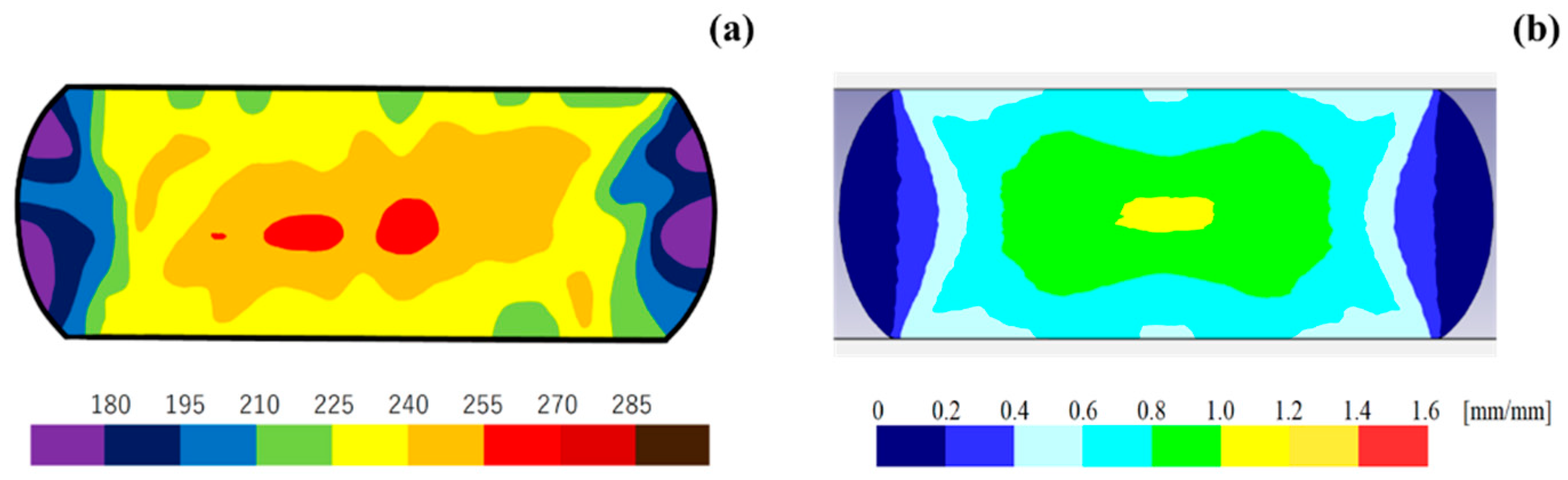
Figure 9 compares the hardness map on the upset pure titanium at r = 50% with the calculated equivalent strain distribution on the cross section of the finite element model at r = 50%. The hardness profile on the upset work is just in fairly good agreement with the simulated equivalent strain (ε
e) distribution. Remember that the stress increment (Δσ) from the yield stress is estimated by Δσ = E
p × (ε
e − ε
y) in the bilinear stress—strain curve under the uniaxial stress state. Here, E
p is the elastic–plastic modulus, and ε
y is the yield strain. The agreement between H and ε
e profiles in
Figure 9 proves that the actual stress state at r = 50% in upsetting is accurately simulated by FEA, with the use of the estimated friction coefficient. That is, the true friction coefficient on the contact interface at r = 50% is 0.05, sufficiently low enough to suppress the shear localization and to sustain the uniform stress state.
3.2. Contact Interface Analysis
Suppression of the work hardening and significantly low-frictional state in the upsetting process with the use of a CS-SKD11 punch suggests that the contact interface condition between the CS-SKD11 punch and the titanium work plays a role in upsetting. SEM–EDX was utilized to analyze the microstructure on the contact interface and to make element mapping.
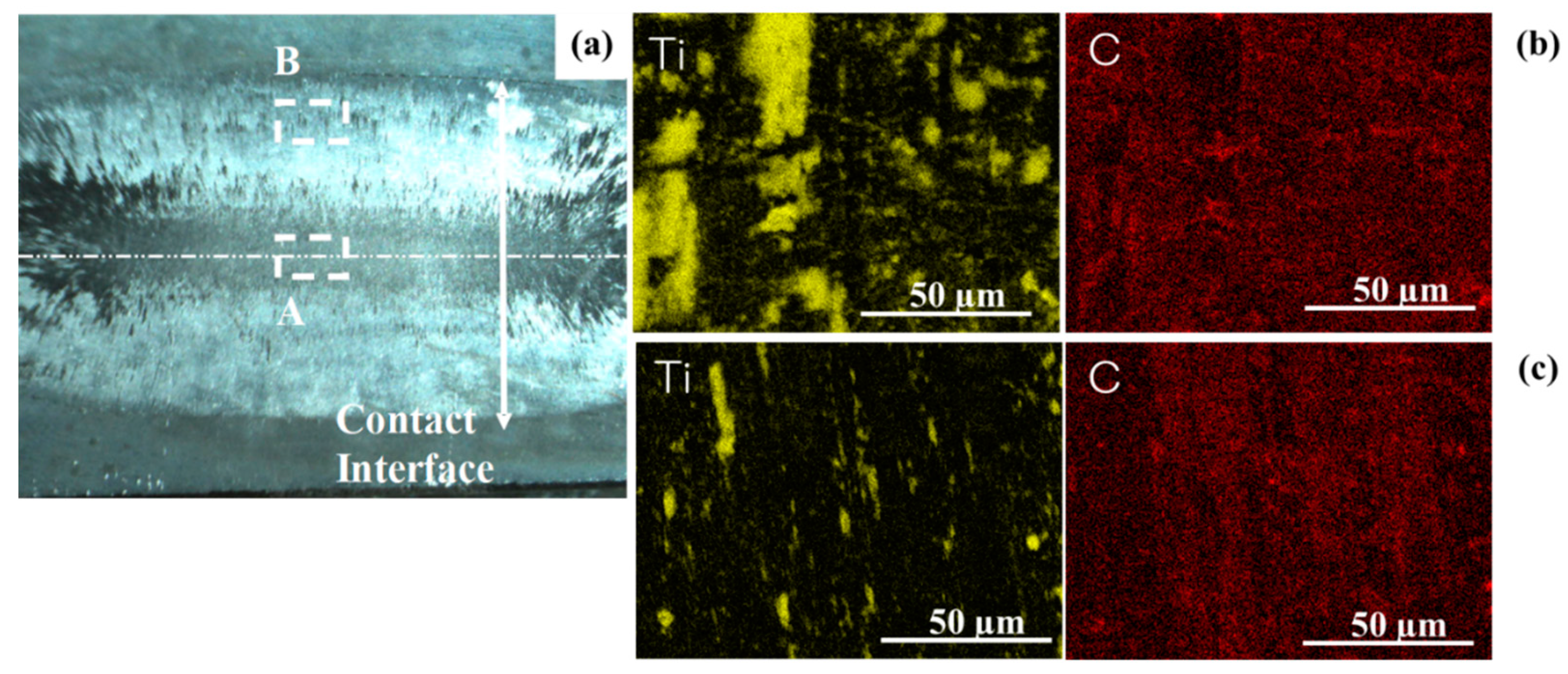
Figure 10a depicts the contact interface on the CS-SKD11 punch after continuously upsetting until r = 50% for 10 times. The white zone in
Figure 10a represents the interfacial area to the upset pure titanium work at r = 50%, while the black zone corresponds to the initial contact interface to the upset work for r < 20%. In both areas, the stripes of deposits were seen in the radial direction from the centerline to the end of interface. This reveals that the deposit film is formed onto the interface by radially flattening the titanium work during the upsetting process. Two zones are selected in this interfacial area; e.g., the A-zone is located at the center, and the B-zone is away from the center.
At the A-zone, the titanium debris fragments deposited on the interface where no carbon was detected in
Figure 10b. However, most of interface was uniformly covered by the carbon film. At the B-zone, the linear titanium fragments were dotted on the interface but most of the interface was wrapped by the carbon layers in
Figure 10c. In correspondence to the radial formation of the deposit film in
Figure 10a, the carbon map is seen in the radial direction in
Figure 10b,c. This implies that the carbon film is gradually formed on the contact interface by flattening the titanium wire.
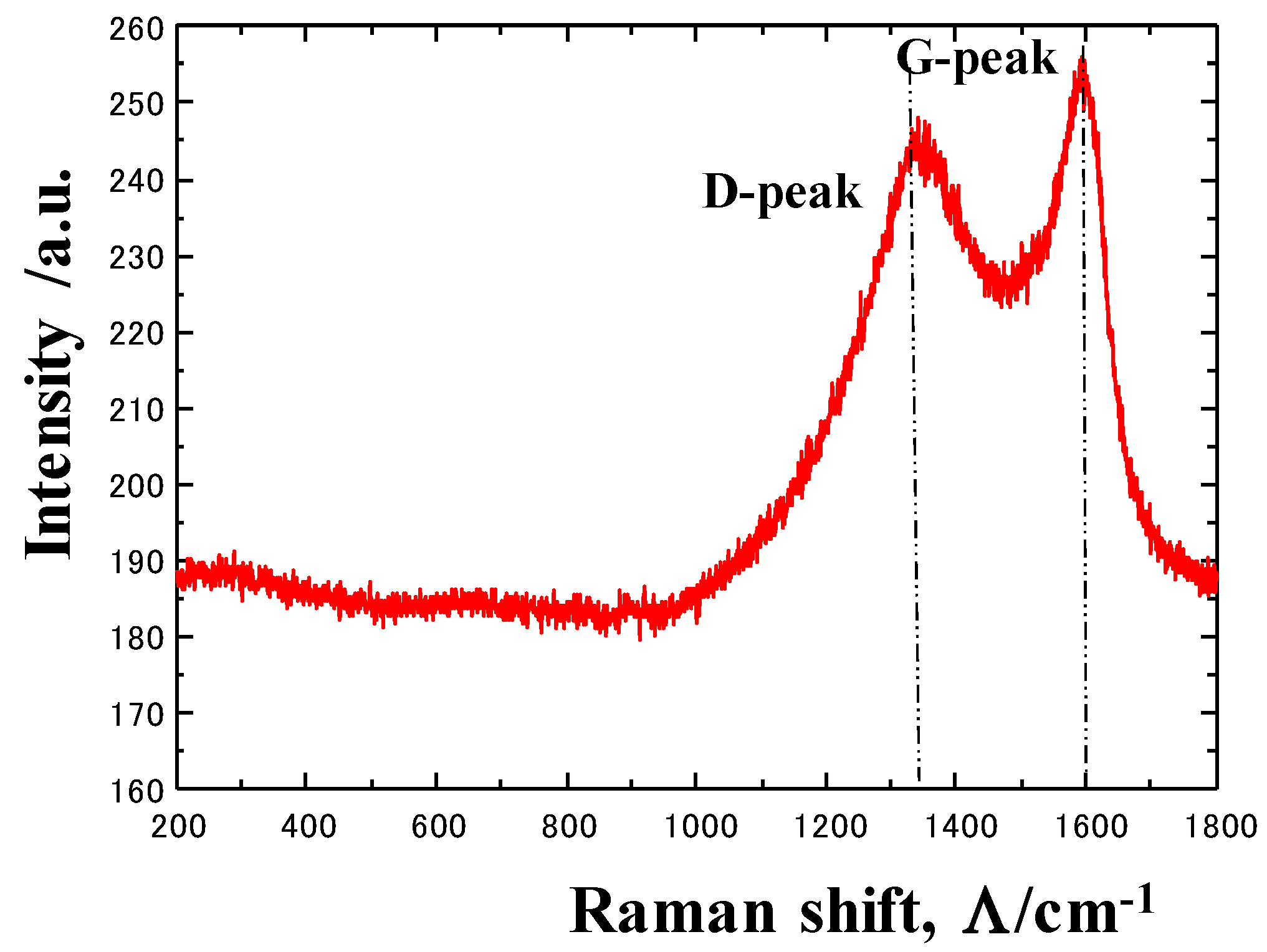
Let us investigate the structure of carbon film by using Raman spectroscopy.
Figure 11 depicts the Raman spectrum at the center of the contact interface. No peaks for titanium oxides and carbides were detected, even in the trace level in the range from 200 cm
−1 to 800 cm
−1, but two main peaks were detected at 1330 cm
−1 and 1600 cm
−1, respectively. After [
27], these correspond to the D-peak for disordered carbon and the G-peak for graphitic carbon, respectively. That is, the carbon film is formed by the agglomeration of the isolated carbon from the CS punch during the upsetting process.
3.3. Near-Net Forging
CS-SKD11 punch and CS-/HT-SKD11 dies were fixed into the die sets for near-net forging in a single shot. In similar manner to the upsetting process, the CS punch has a flat surface, while both the CS/HT dies have a triangular-shaped cavity to be nearly full-filled by titanium work at r = 50%. The pure titanium wire with the diameter of 3.0 mm and the length of 10 mm was utilized as a work.
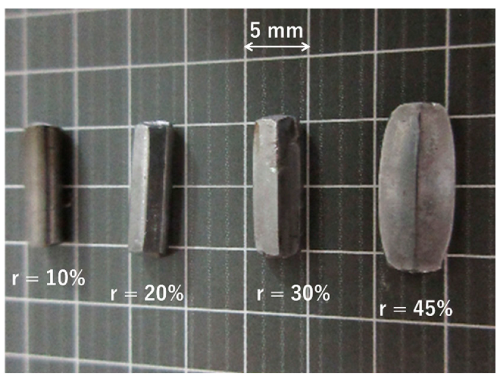
Figure 12 depicts the variation of near-net forged pure titanium work from a 10% in reduction in thickness to 45%. Since the sharp edge was detected on the work at r = 30%, the bottom of triangular cavity in die is filled at r = 30%. For r > 30%, the work gradually flattens and fills into the die cavity.
Figure 13 depicts the load-to-stroke relationship, when increasing the reduction in thickness in the near-net forging of β-phase titanium alloys wires, at each reduction in thickness, by r = 10%, 20%, 30%, 40%, and 45%. Each forging process was performed in a single shot. Except for the load—stroke relation at r = 30%, every four relations are edited into one master load—stroke relationship. As stated before, the deforming work into the die cavity approaches to its bottom around r = 30%; the load slightly increased by full-filling into the bottom of cavity. Hence, overall, the load monotonously increases with the stroke in this near-net forging, except for the local filling into the bottom of die cavity and for the final full-filling process. This implies that the near-net forging with the use of CS-SKD11 punch and die is free from galling anywhere during the forging steps, without the significant influence of the work hardening.
In similar manner to the role of the CS-SKD11 punch in the suppression of work hardening and the reduction in friction during upsetting in
Figure 7 and
Figure 8, the CS-SKD11 die is expected to influence on the filling process into its cavity. Under the same forging experiment conditions, the CS-SKD11 die was exchanged with the HT-SKD11 die, to compare the variation of hardness maps on the cross section of forged β-titanium work, when increasing the reduction in thickness.
As depicted in
Figure 14, no essential difference in hardness mapping was detected in both near-net forgings up to r = 30%, where the bottom of die cavity is filled by the β-titanium work. For r > 30%, the flattening and filling processes advance on the interface between the β-titanium work and die surface. At r = 45%, the die cavity is nearly fully filled by work. When using the HT-SKD11 die, the work near the CS-SKD11 punch and die has higher hardness than 300 HV. Due to this severe work hardening, the flattening and filling processes were hindered, so as not to sufficiently reduce the work. On the other hand, β-titanium work is free from this severe work hardening when using the CS-SKD11 punch and die. The final cross-sectional shape of the triangular bar is attained by this near-net forging.
In the practical operation of precise forging, the original titanium preform is incrementally wrought in multishots during multisteps. When using the CS-SKD11 punch and die, the shaped intermediate preform is yielded in a single shot and in a single step. The pair of CS-SKD11 punch and die in
Figure 4a,c was utilized to incrementally make near-net forging of a circular β-titanium wire into a long triangular bar.
Figure 15 compares the original β-titanium wire with a diameter of 3.0 mm and a length of 70 mm, with the forged long triangular bar, with the reduction in thickness by 45%, in a single shot with three increments. The galling-free and smooth titanium metal flow characterizes this near-net forging process by using the CS-SKD11 punch and die.
4. Discussion
In the conventional forging of titanium works [
1,
2,
7,
8,
28], the punches and dies suffer from the chemical galling or the work–material adhesion to their contact interface, as reviewed in [
29]. This galling behavior is driven by the in situ adhesion of fresh titanium fragments and the in situ deposition of titanium oxide debris particles onto the punch and die surface. Due to the chemical affinity of fresh titanium to die substrates, their contact interface was just covered by fresh fragments only after forging in a single shot. Since the hard titanium oxide debris splash in the air and deposit on the die surface, further forging steps cannot be performed without fine cleansing and polishing in each operation. As demonstrated in
Figure 10 and
Figure 11, the in situ formed carbon tribofilm works as a solid lubricant to hinder the direct contact of fresh titanium work to the die surface and to lower the friction on the interface. No splashing of titanium oxide debris particles was seen during the forging experiments; titanium work has no chance to release its oxide debris particles.
In the normal upsetting and compression of titanium works [
30], the uniform compression mode changes to the plastic localization mode in the early stage of upsetting. In this plastic localization process during the upsetting of cylindrical work, the plastic strains concentrate on the hourglass-shaped zone, and other works deform elastically like a dead zone [
31]. When increasing the reduction in thickness, this plastic strain concentration results in ductile failure at the center of cylindrical work or in shearing fracture. As seen in
Figure 6,
Figure 8 and
Figure 14, less work hardening advances when increasing the reduction in thickness (r), so that the titanium work deforms homogeneously in its cross section. This proves that the in situ solid lubrication by carbon-based tribofilm prevents the titanium and titanium alloy in forging from the shear localization and fatal fracture.
SEM–EDX analysis on the contact interface between the CS punch and titanium work proves that the carbon-based tribofilm is in situ formed on the CS punch surface during forging. Comparison of hardness maps between two forged titanium works respectively by using the HT-SKD11 and CS-SKD11 dies, also proves that a tribofilm is formed on the CS die to suppress the work-hardening behavior. This tribofilm is first formed at the initial contact area in the uniaxial compression with a lower reduction in thickness. It grows in the radial direction from the centerline to the end of punch and die surface with an extension of the contact interface. This co-growth of carbon-based tribofilm, with an extension of the contact interface, sustains the mechanical condition where the tribofilm is present between the die substrate and the deforming titanium work. All through the forging steps, the deforming titanium work is isolated from direct contact to the die substrate, to preserve the galling-free condition.
Solid lubricants such as graphite or MoS
2 powders [
32] could work to form a tribofilm, as long as they were present on the contact interface. Once they were absent, the galling would be ready to occur and result in the seizure of fresh titanium onto the die surface. On the other hand, a thin tribofilm is formed just on the true contact interface to titanium work, when using the CS punch and CS die. Considering the supersaturated carbon content by 3 to 4 mass% [
20], the in situ solid lubrication by this tribofilm works in the long term during forming operations.
After the quantum alloying design on the titanium alloys, a BCC-structured alloy has a higher number of independently working sloping planes than pure titanium with an HCP-crystal structure. However, this superiority of the plastic flow to the β-phase titanium alloy was hindered by the galling wear on the contact interface between the punch/die and the alloy work. When using the CS punch and CS die for upsetting, the contact interface becomes galling-free, so that more homogeneous plastic flow takes place during the upsetting process, as shown in
Figure 8. Even in the near-net forging, this homogeneous plastic flowability is sustained to shape the circular wire to the triangular bar without significant work hardening, as shown in
Figure 14. This reveals that the superiority to the β-phase titanium alloy in plastic flow is fully available in the near-net forging of complex-shaped products, by using the CS punch and CS die.
In addition, the forging-process design is renowned by using the CS punch and CS punch. Under the low friction on the contact interface and the low work hardening of the work materials, the three-dimensional rigid-plastic FEA [
33], without consideration of friction on the punch and die surfaces, provides a way to design the forging procedure with multi-incremental steps for net-shaping. In the conventional design, punch and die maintenance is indispensable during forging operations, since surface damages inevitably occur and deteriorate the forged products. In particular, this type of maintenance is needed at the intermission between successive forging steps to make complex, near-net shaping. Usage of the CS punch and CS die provides a direction to save that intermittent maintenance and to increase manufacturing efficiency.
After theoretical discussion [
34], the carbon and nitrogen supersaturation processes are similar to each other. Even in experiments, the lattice expansion of granular cells in the matrix, the plastic straining process, and the two-phase fine microstructuring must be common between nitrogen- and carbon-supersaturated stainless steels and tool steels [
35,
36,
37]. As partially stated in [
22], the affinity of fresh titanium to isolated nitrogen and carbon atoms from the supersaturated tool steels is different between the two. As demonstrated in
Figure 10 and
Figure 11, no titanium carbides were formed on the contact interface between CS-SKD11 and the titanium work. On the other hand, the nitrogen and titanium maps were coincident to each other on the contact interface between the nitrogen-supersaturated SKD11 punch and titanium work. That is, the titanium nitride or nitrogen-saturated titanium film is synthesized at hot spots on the interface. Further research is necessary to precisely describe this difference in the in situ reaction on the contact interface between nitrogen- and carbon-supersaturated tools.
As partially discussed in [
38,
39], the supersaturation of nitrogen and carbon solutes accompanies the microscopic phase separation of the original stainless steels into solute-rich and solute-poor cells. This implies that zone boundaries between the two phases work as a diffusion path of solute from the matrix to the contact interface under the stress gradient. Further study is also needed to explain the role of microscopic zone boundaries in the isolation process of supersaturating carbon solutes.
5. Conclusions
The near-net forging of titanium and titanium alloy works for products and requires three technological items: a galling-free and low-friction process, an annealing-free and low work-hardening process, and an incremental single-shot process. The carbon-based tribofilm is in situ formed onto the true contact interface between the work and the carbon-supersaturated punch and die, to prevent the punch and die surfaces from adhesion by the titanium work fragments and titanium oxide debris deposits and to sustain the low-frictional state on the punch and die surfaces. The smooth metal flow of titanium work along the punch and die surfaces reduces the work-hardening behavior and lowers the accumulation of strains during forging, even with a high reduction in thickness. This reduction in work hardening saves the annealing steps in the intermission between the successive forging steps. Low friction and low work hardening work as a key to compress the original work to intermediate preforms in a single shot and to precisely shape these preforms to the final product incrementally. Owing to these superiorities over a carbon-supersaturated punch and a carbon-supersaturated die in forging, the present die technology provides a way of manufacturing to yield net-forged products from the raw titanium and titanium alloy feedstock.
Since homogeneous plastic flow is sustained by low friction and low work hardening, the high-reduction forging steps becomes free from shear localization and fatal fracture. In particular, this merit in flowability effectively works in the filling process into die cavities in the final stage of near-net forging. In usual, a sacrifice boss is needed in the plastic-flow control, to increase the dimensional accuracy in forging. These work-material wastes are saved by using the carbon-supersaturated punch and carbon-supersaturated die to improve the materials efficiency in green manufacturing. Various intermittent maintenance is also saved, which promotes cost competitiveness even when net-forging into complex-shaped products.
The isolation and diffusion processes of carbon solute in the carbon-supersaturated substrate has scientific issues to be analyzed. Microscopic phase separation by nitrogen enrichment explains the chemical instability to drive the isolation process. Microscopic-zone boundaries work as a diffusion path of isolated carbon solute to the contact surface under the stress gradient. Die material design is also necessary to make full use of titanium-affinity for the constituent alloying elements of a die.

