Article

Friction Issues over the Railway Wheels-Axis Assembly Motion

1
Polytechnic Faculty, Calisia University, 62-800 Kalisz, Poland
2
Faculty of Process and Environmental Engineering, Lodz University of Technology, 90-924 Lodz, Poland
3
Department of Vehicles and Fundamentals of Machine Design, Lodz University of Technology, 90-537 Lodz, Poland
4
Institute of Material Engineering, Lodz University of Technology, 90-924 Lodz, Poland
5
Faculty of Automotive and Construction Machinery Engineering, Warsaw University of Technology, 02-524 Warsaw, Poland
*
Authors to whom correspondence should be addressed.
Lubricants 2022, 10(2), 26; https://doi.org/10.3390/lubricants10020026
Submission received: 14 January 2022 / Revised: 29 January 2022 / Accepted: 10 February 2022 / Published: 12 February 2022

Abstract

:
The frictional issues during motion of the axis-wheels assembly occurring in contact wheel–rail and in bogie bearing were studied. The influence of greases upon friction therein was also considered. The lateral dynamic behavior of the four-axle freight wagon model with two-axle Y25 bogies equipped with swing bolster was analyzed. Simulation models of such a wagon with bogies with and without swing bolsters were elaborated for calculations considering the nonlinearities of wheel–rail contact geometry and nonlinear methods of bogie stability. In these two options, the cases of empty and fully loaded wagon bodies were considered. The lateral dynamic models with 22 and 24 degrees of freedom were considered to determine the nonlinear critical speeds of a freight wagon. It was found that the resistive torque in bearings of the assembly studied varied nonlinearly with wagon speed. During motion along the curve track, values of such a torque can be higher by 50% in case of the wheel under overloading and lower by 50% in case of the wheel under underloading, respectively, compared to those obtained during motion along straight track.

1. Introduction

Most freight wagons currently in use in Europe have practically one suspension stage and they are designed to travel at speeds of 100–120 km/h on straight track. Increasing this speed for existing designs would be possible, for instance, by changing the stiffness parameters of the first stage suspension. In practice, this would mean agreeing to a very large increase in the stiffness of the wheelset guidance in the bogie frame. However, such a solution would drastically worsen the interaction of the wagon wheels with the curved track, causing the risk of derailment and accelerating wheel flange and rail wear. The paper presents the results of simulation studies necessary to assess the validity of the use in the construction of two-axle freight bogies a swing bolster and thus introducing the second stage of the suspension of the freight wagon. An example of such a concept are the prototypes of the Y25 family of freight bogies built in Poland in the years 1993–1995, in which a swing bolster was introduced. This solution was granted European patent no EP 0762965B109.09.1998 and applied in bimodal wagons [1]. The term “bimodal wagon” means that in the structure of a freight wagon there are both railway elements (bogies) and road elements (in this case a specialized semi-trailer of a road tractor—Figure 1). The results of calculations of nonlinear critical velocity of a freight car with bogies equipped with a swing bolster have not been published in the literature so far. This was the main motivation for the authors of this paper to perform such simulation studies, the simulation models of a freight wagon.
With Y25 bogies in the version without a swing bolster and with a swing bolster were prepared in the Vi-Rail program and used in calculations considering the nonlinearities of wheel–rail contact geometry and nonlinear methods of bogie stability. In these two options, the case of empty and fully loaded wagon bodies were considered. Necessary simulations, according to the lateral dynamics of the freight wagon moving at a sufficiently high and constant speed, were made on the straight track. Complementary calculations were also performed on a curved track with a small radius of curvature equal to 150 m. In this case, the wagon models were moving at the maximum speed appropriate to the given curve radius and wear numbers according to the wheel/rail contact were analyzed. The motion of a wagon is always accompanied by friction and wear processes in contact between wheels and rails and in bearings. The evaluation of such a friction process was a goal of the present study.

2. Friction in Wheel–Rail Contact

Rail-wheel lubrication plays an important role in the limitation of wear, friction and noise, especially on curves [2].
Cheng [3] found the high effect of the radius of railway curved tracks on the slips in the wheel–rail track contacts, always occurring in the tightly curved tracks. The author reported the generation tendency of the self-excited vibrations in the wheel–rail track system unstable, particularly, on the tightly curved tracks.
The utilized friction between the wheel tread and the top of the rail (rail running surface) needs to be controlled and kept within a particular range of friction coefficients, below 0.5 relating to the non-lubricated (dry) contact [4]. Such a range allows the obtaining of the minimum traction forces without wheel slippage or a long braking distance [4].
Trummer et al. [5] suggested the maintaining of intermediate values of the coefficient of friction between a wheel tread and the top of the rail to decrease frictional tangential contact forces. Such a decrease can be achieved using top-of-rail products. The mentioned intermediate values of friction coefficient facilitate a reduction of energy consumption and fuel costs, as well as damage to the wheel and rail surfaces, such as, e.g., wear, rolling contact fatigue and corrugation.
The top-of-rail friction modifier (TOR-FM), as reported in 2003 by Eadie et al. [6], can be utilized for traction force control. According to [4], various methods are utilized for implementation of TOR-FMs at the wheel–rail interface, among which stationary wayside systems are advised when a distance of a few kilometers is to be covered. An on-board system is preferred when an area of many kilometers must be covered, and focus is more on particular trains. However, according to [2], a huge amount of lubrication is wasted during application.
The friction coefficient can decrease down to 0.2, or even lower, with the presence of water or excess friction modifier [7], and to even lower values in the case of crushed leaves [8]. Such a low friction enhances the risk of a prolonged braking distance and wheel slippage.
Lemma et al. [9] reported that the friction coefficient in the wheel–rail interface for non-lubricated line sections reached values around 0.6 compared to these of 0.3 for areas with, e.g., top-of-rail lubrication. During snowy conditions, such a friction coefficient was also weakened.

3. Bearings Utilized in Railway Applications and Vehicles Equipped with Bogies

3.1. Types of Bearings for Railway Applications and Vehicles Equipped with Bogies

Manufacturer of bearing, such as Schaeffler (INA, FAG) [10], NSK [11] or SKF [12], proposed three kinds of design for roller bearing predestined for railway application and vehicles equipped with bogies. They include:
-
Tapered roller bearing units;
-
Cylindrical roller bearings and cylindrical roller bearing units;
-
Spherical roller bearings.
The modern trend imposes the use of factory pre lubricated and sealed bearing units. The SKF tapered roller bearing units (TBUs) [12] or Schaeffler tapered roller bearing units (TAROL) [10] can be applied for various rolling stock and freight cars. SKF cylindrical roller bearing units (CRUs) are predestined for the mentioned vehicles, except freight cars with adapter design reaching the speed values of up to 120 kph. Cylindrical roller bearings can be applied to diesel and electrical locomotives, metro cars, light rail and tramways and freight cars with a closed axlebox reaching a speed below 120 kph [12]. The Schaeffler cylindrical roller bearings can be applied in wheelset bearing arrangements of all types for standard gauge railways and local trains [10]. SKF spherical roller bearings can be used in freight cars with a closed axlebox reaching a speed below 120 kph [12]. Schaeffler spherical roller bearings are used in wheelset bearings for freight wagons, locomotives and other rail vehicles [10].
The so-called “open bearings” needing sequential additional greasing are still used for some established axlebox and bogie designs or for after-market requirements [12].
The SKF TBUs have been standardized by the Association of American Railroads (AAR) for adapter applications and require case carburized steel for inner and outer rings as well as rollers. For high speed and very high-speed applications, both cases were carburized and through-hardened steel was used, depending on the application requirements [12].
Tapered roller bearing units (TBUs), which is also considered during present study, comprises two inner rings, one common outer ring, two tapered roller and polymer cage assemblies, a central polymer spacer, grease fill and two sealing systems, such as garter, labyrinth-lip (LL), energy efficient labyrinth-lip (LL E2) or labyrinth type. Various lateral spacers, backing rings and end caps with their locking device can be also introduced to the bearing assembly [12].
According to [13,14], tapered roller bearings can transmit axial and radial forces due to its inclination to the rotation axis. However, an optimal response requires keeping of the tolerances of the rollers and their clearance at tighter levels than the one of cylindrical bearings.
The through-hardened steel is usually used for bearing rings and rollers in applications, such as locomotives, multiple units, passenger coaches, mass transit vehicles as well as freight cars with closed axlebox designs [12].

3.2. Lubrication of Bearings for Railway Applications and Vehicles Equipped with Bogies

Railway bearings can be lubricated by grease matched to the AAR specifications [10,11,12] or mineral oil [11,12].
The minimum requirements for greases for axlebox applications are presented in the European Standard EN 12081 [15]. The latter is focused on lithium soap grease, NLGI grade 2 (National Lubricating Grease Institute). It is predestined the use of a grease with mineral base oil with a viscosity of 100 mm2/s at 40 °C. However, the mentioned standard allowed the use of other greases for more demanding applications. For example, bearing units for high-speed applications can be lubricated using greases with lower base oil viscosity.
Cyriac et al. [16] investigated the yield stress and start-up torque for NGLI(1-2) CaS/MS (synthetic (PAO)/mineral base oil 80/8.6 mm2/s at 40/100 °C + calcium sulfonate complex thickener), NGLI2 CAS/M (mineral base oil 420/27 mm2/s at 40/100 °C + calcium sulfonate complex thickener), NGLI3 Li/M (mineral base oil 99.9/10 mm2/s at 40/100 °C + lithium 12-hydroxy stearate thickener), NGLI2 Li/SS (semisynthetic base oil 41.9/7.5 mm2/s at 40/100 °C + lithium 12-hydroxy stearate thickener), NGLI(2-3) LiC/PAO (synthetic PAO base oil 191/42 mm2/s at 40/100 °C + lithium complex thickener) and NGLI(2-3) Pu/E (synthetic ester base oil 70/9.1 mm2/s at 40/100 °C + polyurea thickener) greases commonly used for lubrication of rolling bearing. Both parameters varied exponentially with temperature where the exponent changed below a low-temperature break point. Such a break point related to the pourpoint of the base oil, while the start-up torques of the greases were much higher compared to that of their coherent bled oils. The start-up torque is often applied to determine the low-temperature limit of a grease, which is much lower than the break point.
According to [17], SKF developed a railway grease, LGRT 2, for the lubrication of axlebox bearings of locomotives, passenger coaches, freight wagons, diesel and electrical multiple units, as well as commuter trains, metro cars, light rail vehicles and tramways. This grease is applicable for use at speeds of up to 200 km/h and, in some specific cases, even higher speeds. This grease links a lithium hydroxy stearate soap grease developed with a highly refined NGLI(2-3) mineral base oil (100/11 mm2/s at 40/100 °C). It comprises additives providing a proper resistance against oxidation, wear and corrosion. This grease does not contain solid ingredients and has a good water resistance.
According to [18] spherical roller bearings in railway car wheels are critical components, whose failure may be very dangerous. They studied several fully formulated commercial greases applied in the wheel bearings of five ore cars operated in northern Scandinavia. They found that the shear stress of the grease at a certain shear velocity (the certain yield stress (CEY) value) was highly affected by the grease formulation. The bearing’s wear, electrical damage and corrosion also depended on the grease formulation.
Bosman and Lugt [19] studied the microstructural changes influenced by water occurrence in commercially available calcium sulfonate complex grease, often used for rolling bearing lubrication. They found that the formation of large (inverted) micelles, with a diameter of up to a few micrometers, was the main mechanism for the water absorption, which highly affected the rheological and lubricating properties of these grease types. They also reported that the size distribution of the micelle structure was affected by the amount of water mixed into the bulk grease.
The properties of grease can be improved by the addition of various nanoparticles (NPs), such as SiO2 [20], MoS2 [21], CuO [22], TiO2 [23] or ZrO2 [24,25]. However, the effectiveness of addition of NPs into grease can be limited by the phenomenon of NPs agglomeration [25].
Interestingly, Pape and Poll [26] studied graphene platelets as a dry lubricant and as a grease additive for rolling contact. They found that when using them, the wear resistance under reciprocating motion was much better compared to the case with a lack of such platelets. The friction was also decreased in comparison to the case of pure grease lubrication as well as to the case of spherical graphite nanoparticles, independently to the platelets’ thicknesses. They stated that graphene layer can also be used for bearings without increased bearing clearance and the graphene platelets create a very thin protective layer on the surface. Such a layer has a high wear resistance and protects the surface from oxidation. The authors also reported that graphene platelets decrease friction at lower sliding speeds, particularly compared to the graphite nano spheres.

3.3. Frictional Torque and Temperature in Roller Bearing

Yamanaka and Zenbutsu [27] pointed that the friction torque in tapered rolling bearing is affected by four factors:
-
Rolling friction between the raceway surfaces of inner and outer rings and rolling surfaces;
-
Sliding friction between the inner ring rib and roller end surface;
-
Churning resistance of lubricating oil;
-
Sliding friction between the rollers and cage.
The latter has the lower effect compared to the others on the total friction in TBUs.
Zhang et al. [28] studied the effect of the roller skewing on the resistive torque of dry-lubricated TRB for the axial preload by force and by displacement. They found that a proper roller skewing angle under axial force preload lowered the TRB resistive torque. However, the roller skewing angle cannot be higher than a certain critical value, otherwise, it increases the TRB resistive torque in a steep manner. Such a critical value of the roller skewing angle depended on the friction coefficient and cage pocket clearance.
Studying the behavior of tapered roller bearings, Gupta [29] found that the skew of rollers in such bearings enhanced with an increase of friction. Additionally, the pivoting of rollers was complex and affected by friction coefficient values and cage clearances.
Schwarz [30] investigated the temperature distribution of tapered roller bearing disposed in back-to-back mounting and lubricated by oil bath. Under constant loading, the bearing frictional torque initially enhanced with the speed increase from 1000 to 2500 r/min under thermal stabilization. Then, the torque remained relatively constant when speed increased further up to 3000 rpm and next slightly weakened for higher speeds. Besides, the inner raceway temperature was about 2–4% higher than that of the outer raceway. The formulae of frictional torque for tapered roller bearings were also proposed in [31,32,33].
Zhou and Hoeprich [34] elaborated an analytic tapered roller bearing torque model allowing for predicting the torque components for each roller due to raceway rolling, raceway moments due to EHL pressure distribution and frictional force of rib-roller end contact. The effects of roughness of contact surfaces, the ratio of EHL film thickness to composite surface roughness and film temperature distribution are also considered in the model.
Yan et al. [35] experimentally found that for the total heat rate of each column rollers, heat generation of the raceway was much higher than the other parts. The heat generation of the rib was the most important for the local transient temperature rise of railway bearing. Additionally, the highest temperature of the inner ring was observed in the rib.

3.4. Failures in Roller Bearing

According to [36], defects in bearings are likely to result in hot axle conditions, when the actual temperature of axlebox becomes higher than about 70 °C. Hot axle conditions can be manifested by the increased temperature of the axlebox, cracks in the axlebox cover and spillage of grease.
Such defects can be caused by:
-
Improper and/or excessive/inadequate grease;
-
Bearing clearance not within prescribed limits;
-
Journal finish and diameter not in accordance with the OEM;
-
Excessive or inadequate lateral clearance between axle box covers and bearings;
-
Too little or too much gap between rollers and roller rings.
According to [14,37] the most frequent axle failures are caused by:
-
Loose bearing failure 23%;
-
Water etch 20%;
-
Wheel tread defect 13%;
-
Fatigue spalling 13%;
-
Bearing destruction 12%;
-
Mechanical problems 6%;
-
Lubrication problems 4%;
-
Adapter (displaced, worn, wrong size or broken) 4%;
-
Displaced seal 3%;
-
Truck related failure 2%;
-
Application defects about 0%;
-
Manufacturer, remanufacturer or reconditioner defect about 0%.
Such failures are often accompanied by heat generation inside bearings and generation of debris, which can affect the resistive torque of the bearing. The latter strongly depends on a proper amount of lubricant and its features, particularly the viscosity. The latter varies with temperature, amount of water, debris and contaminations, both of which are affected by the technical state of the bearing seal.

4. Materials and Methods

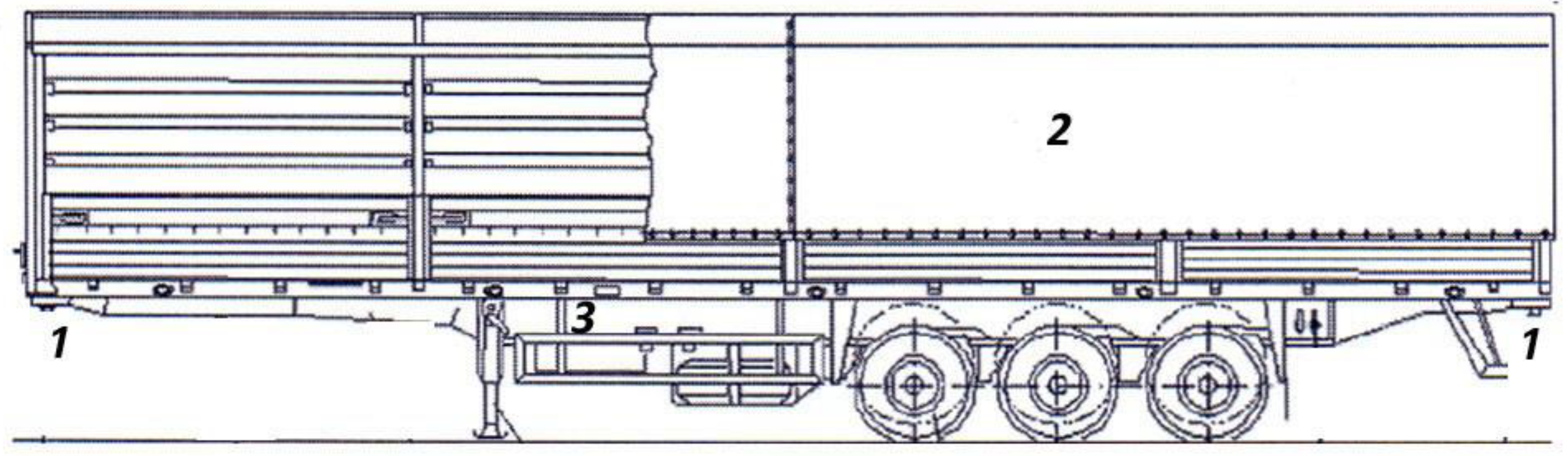
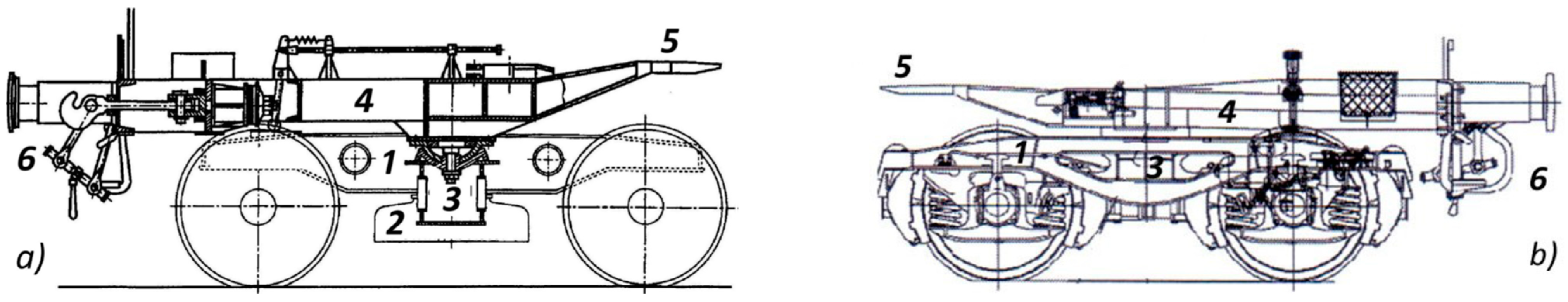
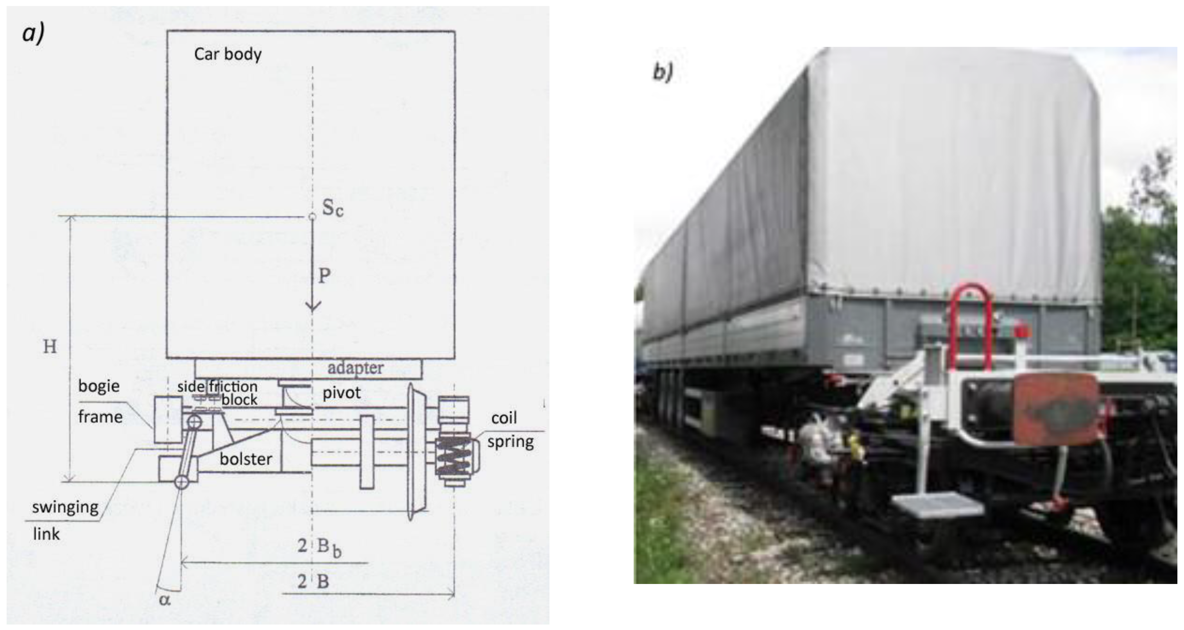
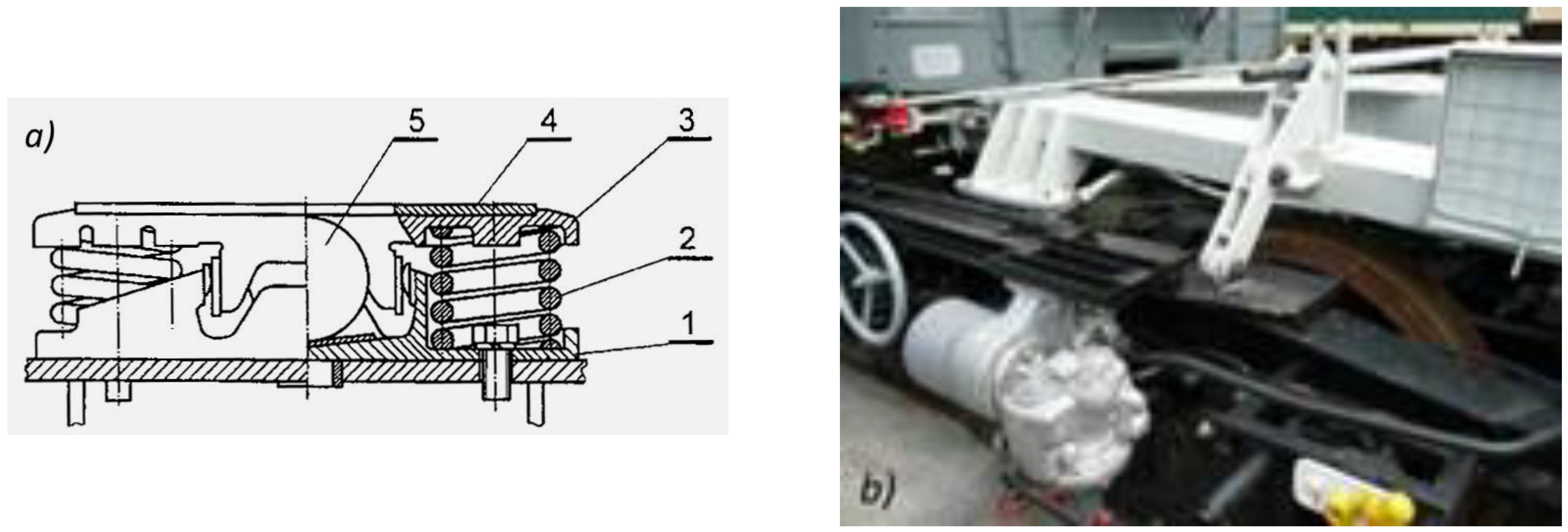
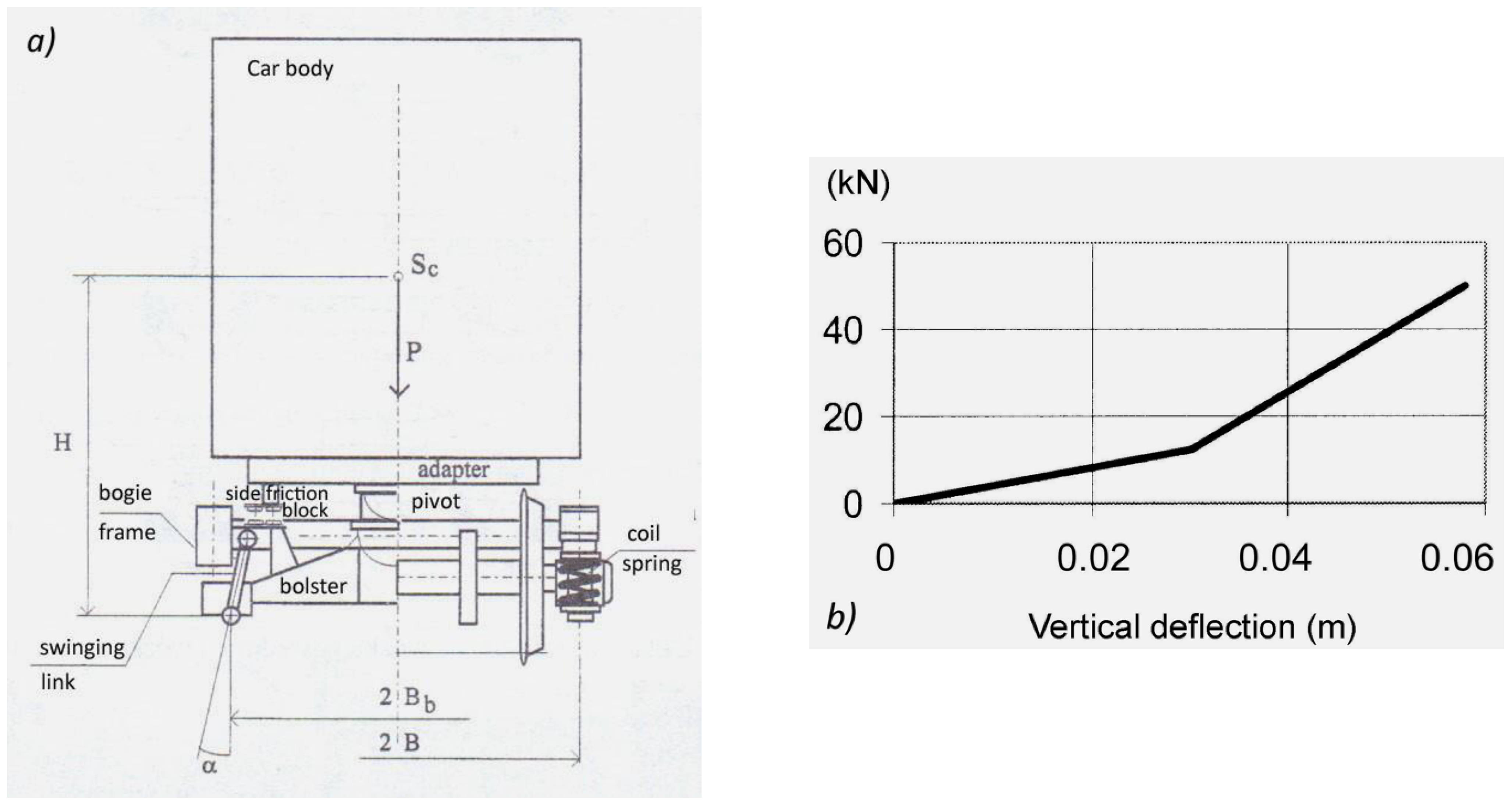
4.1. Structural Elements of a Freight Wagon in the Bimodal System

In the bimodal system, the freight wagon structure consists of two bogies equipped with adapters and a car body in the form of a specialized semi-trailer of a road tractor. The car body is rigidly connected to the bogie frames via adapters in the horizontal loading system and rests on the bogie frames via spherical central pivots and side friction blocks [1]. The car body and reinforced semi-trailer frame are denoted in Figure 2 by the indices “2”and “3”, respectively. Sockets, necessary to connect the adapter to the semi-trailer, are denoted by the subscripts “1”. Figure 2a,b show the idea of two solutions of freight bogies with adapters “4”. It should be noted that adapters are one-piece frames containing coupling devices “6”. In the first case the nest of central pivot “3” is located on the swing bolster “2”, which is connected to the bogie frame “1” through two pairs of hangers (Figure 2a). In the second case, the nest of central pivot rested directly on the bogie frame, Figure 2b. In both cases, two friction blocks are located on the side beams of the bogie frame. A diagram of the car body support on bogies equipped with swing bolsters is presented in Figure 3a. Figure 3b shows a photograph of the prototype of the Polish bimodal freight wagon. Elements of side friction block are shown in Figure 4a. The vertical deflection of the springs “2” is limited by the steel roller “5”. The sliding plate of the adapter remains in contact with the steel plate “4” of the side friction block. Forked guidance of wheelset axle in the bogie frame is shown in Figure 5a. Between the bogie frame “1” and the bearing housing “7”, there are two sets of cylindrical coil springs indicated as “2” and “3”. Vertical and lateral displacements of the bearing housing are accompanied by dry friction forces. Mounted at an angle of 25°, the Lenoir link “6” generates longitudinal force component, that presses the plug “4” against the vertical friction plate mounted on housing “7”. The flat surfaces of these elements slide over each other and, in that way, damping of vertical and lateral vibrations of the wheelsets in relation to the bogie frame is achieved.

4.2. Simulation Model of the Freight Wagon

To study the lateral dynamics of the modeled wagons, the simulation model was elaborated using the Vi-Rail program. A wagon with a one-stage suspension was modeled as a four-axle mass-spring-damping, rigid-body mechanical system, including a car body, two adapters, two bogie frames and four wheelsets. In the case of two-stage suspensions, two swing bolsters were also considered. Each wheelset, bogie frame, swing bolster and the car body had three, four, two and one degrees of freedom, respectively. Therefore, the wagon model without swing bolsters in the structure of bogies had 22 degrees of freedom, while the model with bogies equipped with swing bolsters had 24 DOFs. Individual elements of simulation models were perfectly rigid bodies. The position of a given element was described by 3 Cartesian coordinates towards an immovable, global reference system, and the attitude of each element was defined by 3 Euler angles [38]. If correctness of the structure of a wagon model containing rigid bodies and kinematic pairs was verified, the Vi-Rail program autonomously generated a set of differential-algebraic equations of motion.
Freight wagon models were treated here as a mechanical system with the capability to oscillate. They were moving at a constant speed along a straight track and this speed was the changing parameter in each case of implementation of the kinematic excitation from the track. Calculations were started with a speed of 50 m/s on a smooth straight track. After the wagon had covered 30 m, its motion was disturbed by introducing a kinematic forcing in the form of a transverse wave with constant length equal to 1 m and exciting amplitude equal to one of assumed values varied from 0.001 to 0.007 m. Thus, for a given speed, seven simulations were performed by varying the amplitude of the kinematic forcing. Then, the speed was decreased in intervals of 1 m/s and the procedure was repeated.

4.3. Wheel–Rail Contact Model

The nonlinear geometry of wheel–rail contact was applied. When the wagon was moving along the straight track with constant speed, and movement of the wheelsets was disturbed in lateral horizontal plane, then wheelsets started to hunt. In each wheelset position relative to the track center line, the Vi-Rail program solved the “normal task” (RSGEO procedure was used) to establish the shapes and sizes of contact patches. Then, the FASTSIM procedure was executed necessary to solve the “tangent task” and establish tangent forces in contact patches [39]. These forces were calculated as the functions of slide creepages and spins between wheels and rails. With nonlinear wheels and rails profiles, contact patches were not elliptical. Hence, contact parameters were computed using a modified FASTSIM procedure, proposed by Kik and Piotrowski [40].
It was assumed that the friction coefficient in each wheel–rail contact in the modelled freight wagon with bogies equipped with swing bolsters was constant and its value was equal to 0.4.

4.4. Computational Parameters of the Simulation Model

The following parameters of the wagon model were considered in the simulation calculations: masses and main inertia moments of the individual rigid elements, locations of the center of gravity of each rigid part, stiffness and damping of primary and secondary suspension elements.
According to [1], numerical values of geometrical and mass parameters of a wagon model were following:
-
wagon base was equal to 14 m,
-
bogie base was equal to 2.3 m,
-
total mass of empty wagon was equal to 25,070 kg, and that of the loaded one was equal to 48,070 kg,
-
mass of empty wagon body was equal to 11,000 kg and that of the fully loaded one was equal to 34,000 kg,
-
wheelset mass was equal to 1700 kg.
-
nominal wheel diameter was equal to 0.92 m.
In case of the wagon model with bogies equipped with swing bolsters, there were two stages of suspension. Primary suspension consisted of steel coil springs and a friction damper with Lenoir link. Secondary suspension was formed with a swing bolster. In the model without a swing bolster, only the primary suspension was considered.
According to [1], the values of stiffness and damping coefficients for primary and secondary suspension were following:
-
lateral stiffness of primary suspension spring was equal to 3890 kN/m for the empty wagon and to 5560 kN/m for the loaded one;
-
longitudinal stiffness of primary suspension spring was equal to 1000 kN/m;
-
lateral stiffness of secondary suspension spring was equal to 113 kN/m for the emp-ty wagon and to 351 kN/m for the loaded one;
-
vertical stiffness of secondary suspension spring was equal to 100,000 kN/m;
-
damping coefficient of primary suspension in longitudinal, lateral and vertical directions was equal to 0 kNs/m, 7 kNs/m and 7 kNs/m, respectively, for the case of the empty wagon, and to 0 kNs/m, 12 kNs/m and 12 kNs/m, respectively, for the case of the loaded one;
-
damping coefficient of secondary suspension in lateral direction was equal to 0 kNs/m;
-
vertical stiffness of outer spring in primary suspension was equal to 1548 kN/m;
-
vertical stiffness of inner spring in primary suspension was equal to 3748 kN/m;
-
vertical stiffness of side friction block spring was equal to 2740 kN/m;
-
damping coefficient of side friction block in longitudinal and lateral directions was equal to 0.1 kNs/m;
-
damping coefficient on the central pivot surface was equal to 0.1 kNs/m.
These values are consistent with the real measurements results published among others in [41].
The geometry description of a straight track and other track substitute parameters were consistent with that given in [38] and [42]. The main information used in the calculations were as follows: directional stiffness of the railway track, track gauge, rail inclination, lateral outline of rail heads with UIC60E profile and lateral outline of wheels with S1002 profile. The regular track gauge of 1.435 m was assumed, and 0.025 rad angle of track inclination was considered.

4.5. Wear Numbers for Wheels and Rails on a Curved Track with a Small Curve Radius

To evaluate the effect of the excessive stiffness of the wheelset guidance in the bogie frame, complementary examinations were performed on the track consisting of three sections: 50 m of straight track, 50 m of transition curve, full arc with a radius of 150 m and superelevation of 0.15 m, according to the norm [43]. For the wagon models moving at the speed of 15 m/s, the wear numbers for wheels and rails were analyzed on a track having the parameters. To evaluate the dynamic properties of wagon models, the energy model (often referred to as “T-gamma model” based on an assumption that the amount of the lost material is the energy dissipation function in the wheel–rail contact patch) was used [44]. Numerical values of wear numbers W n in the contact patch were computed as a sum of the products of tangential forces and creepages on a longitudinal and lateral directions, as in Equation (1) [45]:
W n = T γ = T x · γ x + T y · γ y ,
The wear number can be physically interpreted as an amount of energy dissipated on one meter path, performed by tangential forces in the contact patches, when a vehicle is in motion with constant speed.
The values of wear numbers were analyzed in reference to the external wheel of a leading wheelset in the front bogie of the wagon. The case of a wagon model with bogies equipped with the swing bolsters and a wagon model with bogies without the swing bolsters, but with huge stiffness values of primary suspension, were compared.

4.6. Friction in the Set of Bearings in the Wheels-Axis Assembly in Bogie

The wheel–rail contact can be loaded by force with three components, namely the normal one, the peripheral one and the transverse one. The determination of actual values of each component is a complex issue because they are affected by forces acting on the moving wagon, the geometrical parameters of the railway track (in particular its curvature), the wagon and its bogies as well as the distribution of contact stresses and geometrical parameters of the wheels and rail profiles. To simplify the analysis, two cases of motion were considered: the first along a straight track and the second along a curved one.
In the first case, it was assumed that normal force components, F z , were equal to normal component of rail reaction Q [45] and were calculated from Equation (2). The value of the vertical component of friction force in contact wheel–rail [45] was omitted as a very small one:
F z = 0.5 · ( 0.25 · G w ) = 0.125 · G w
where 0.25 · G relates to the normal load of the bogie axis, G —wagon weight.
In the second case, the normal force component F z is assumed to be equal to:
-
0.75 · ( 0.25 · G ) for a wheel under overloading (running on the inside of the curve);
-
0.25 · ( 0.25 · G ) for a wheel under underloading (running on the outer side of the curve).
The transverse force component F y has been estimated as follows:
For the case of motion along a straight track, the maximal value related to the case of assumed minimal values of a ratio Y / Q between the ‘so called’ leading force Y and normal component of rail reaction Q. This ratio can take values from the range <0.5, ( Y / Q ) m a x > [45]. Thus, its assumed minimal value is equal to 0.5.
The leading force Y [45] was assumed to be close to the transverse force. Therefore, the transverse force is calculated from Equation (3):
F y = 0.5 · [ F z = 0.5 · ( 0.25 · G w ) ] = 0.0625 · G w
In the case of motion along a curved track, for the wheel under overloading, the maximal value of the transverse force component F y related to the case of a minimally assumed value of a ratio Y / Q , i.e., equal to 0.5. Thus, the transverse force component F y is estimated from Equation (4):
F y = 0.5 · [ F z = 0.75 · ( 0.25 · G w ) ] = 0.09375 · G w
In the case of motion along a curved track, for the wheel under underloading, the maximal value of the transverse force component F y related to the case of maximal assumed value of a ratio Y / Q . This maximum value is limited by the possibility of a wagon overturning occurrence [45]. There are three criteria for such limits.
The first one was proposed by Nadal [46,47,48,49,50] and takes a form of Equation (5) [45]:
Y Q = tan γ μ 1 + μ · tan γ
where: μ —friction coefficient in wheel–rail contact, γ —the largest possible angle of wheel–rail contact, which values was assumed to be equal to 60°.
The second criterion was proposed by Weinstock [46] and takes the form of Equation (6) [45]:
Y Q = tan γ μ 1 + μ · tan γ + μ
The third criterion was proposed by Matej [45] takes a form of Equation (7):
Y Q = t x · μ · sin Ψ · cos α cos γ t y · μ · ( cos Ψ sin Ψ · sin α · tan γ ) + cos Ψ · tan γ + sin Ψ · sin α t x · μ · sin α cos γ + t y · μ · cos α · tan γ + cos α
where:
  • t x = T x T —the non-dimensional ratio of the peripheral friction force and the total friction forces in the wheel–rail contact [45]. Its values can be in range <0,1>;
  • t y = T x T —the non-dimensional ratio of transverse friction force and the total friction force in the wheel–rail contact [45]. Its values can also be in range <0,1>;
  • T —the total friction force calculated from Equation (8) [45].
T = μ · Q = T x 2 + T y 2
  • α = sin 1 ( Δ x R ) —an angle of the anticipation of wheel slip on the rail. Its value was assumed to be equal to 0, for each case at present study;
  • Δ x —the anticipation of wheel slip on the rail;
  • R —radius of the wheel;
  • Ψ—an angle of wheel slip on the rail. Its values were assumed to be in range <0,0.5> mrad.
It was assumed that t x = t y for each considered case of calculations. Thus, the values of peripheral and transverse friction force in wheel–rail contact can be estimated from Equation (9):
T x = T y = μ · Q 2
The bogie comprised wheels supported relative to the axis fixed to the bogie body using tapered roller bearing units. Each wheel utilized one TBU. It was assumed that one axis is loaded by one-fourth of the value of the wagon weight. The radial force acting on the bearing is the one resulting from the component of gravity and the tangential circumferential force acting on the wheel, as is given by Equation (10):
F R = ( φ · 0.25 · G w ) 2 + T x 2
where: φ 0.5 ,   1 —factor, which value depends on the actual configuration of force loading the wheel-axis assembly; in most cases, and especially when driving on straight sections of the track, this value is equal to 0.5, but also can reach 0.25 or 0.75 when in motion along a curved section of tract is of the interest.
The axial force acting on the bearing is derived from the tangential axial force acting on the wheel and calculated from Equation (11):
F a = Y
The total force loading bearing is calculated from Equation (4).
The maximum static axlebox load per bearing arrangement/unit is determined from Equation (12) [12]:
G = G 00 G r 2
where:
  • G—maximum static axlebox load [kN], G 00 —maximum static axleload [kN], G r —weight of the wheelset [kN]
It was assumed to estimate the radial force loading axlebox is calculated from Equation (13):
F R G = m a x ( F R , G )
Based on the static axlebox load, the mean radial load is obtained from Equation (14) [12] after considering any variations in the payload as well as any further dynamic radial forces:
K r = f 0 · f r d · f t r · F R G
where:
  • Kr = mean radial load [kN], f 0 = 1—assumed payload factor, f r d = 1.3—assumed dynamic radial factor, f t r = 1—assumed dynamic traction factor.
The mean axial load is determined from Equation (15) [12] after considering the dynamic axial forces on the axlebox:
K a = f 0 · f a d · F R G
where:
  • K a —mean axial load [kN], f a d = 0.1—assumed dynamic axial factor.
The corrected mean radial load is calculated from Equation (16) [12]:
F R C = K r + 2 · f c · K a
where:
  • f c —factor calculated from Equation (17) [12]:
f c = h · D a l
where:
  • D a = 130 mm—shaft diameter, l = 150 mm—distance between two load centres, h = 0.1—factor, which value related to the case of the load acting near to the middle plane of the bearing.
The resistive torque of bearing M is calculated from Equation (18) [51]:
M = M r r + M s l + M s e a l + M d r a g
where:
  • M r r —the rolling frictional torque affected by lubricant starvation and inlet shear heating [Nmm], which is calculated from Equation (19) [51]:
M r r = Φ i s h · Φ r s · G r r · ( ν · n ) 0.6
where:
  • n = v 0.5 · D w · 60 2 · π —rotational speed [rpm], v 50 kph—assumed wagon speed, ν = 130 mm2/s—kinematic viscosity of the base oil of the grease at temperature of 20 °C, Φ i s h —the inlet shear heating reduction factor calculated from Equation (20) [51]:
Φ i s h = 1 1 + 1.84 · 10 9 · ( n · d m ) 1.28 ν 0.64
where:
  • d m = 0.5 · ( d + D ) —bearing mean diameter [mm], d = D a = 130 mminner diameter of bearing, D = 230 mm—outer diameter of bearing
  • Φ r s —the kinematic replenishment/starvation reduction factor calculated from Equation (21) [51]:
Φ r s = 1 exp ( K r s · ν · n · ( d + D ) K z 2 · ( D d ) )
where:
  • K r s = 6 10 8 —the replenishment/starvation constant for grease lubrication, K z = 6 —bearing type related geometric constant, for tapered roller bearings.
  • G r r —variable determined from Equation (22) [51]:
G r r = R 1 · d m 2.38 · ( F R C + R 2 · Y b · F a ) 0.31
where:
  • R 1 = 2.31 · 10 6 , R 2 = 10.9 —geometrical constants for tapered roller bearings.
  • Y b —the axial load factor calculated from Formula (23) [51].
{ K a F R C e Y b = 1.6 K a F R C > e Y b = 2.3
where:
  • e = 0.43 —the assumed parameter for tapered roller bearing.
  • M s l —the sliding frictional torque affected by the quality of lubrication conditions [Nmm], which is calculated from Equation (24) [51]:
M s l = G s l · μ s l
where:
  • G s l —variable determined from Equation (25) [51]:
G s l = S 1 · d m 0.82 · ( F R C + S 2 · Y b · F a )
where:
  • S 1 = 0.019 , S 2 = 2 —geometrical constants for tapered roller bearings.
  • μ s l —sliding friction coefficient calculated from Equation (26) [51]:
μ s l = Φ b l · μ b l + ( 1 Φ b l ) · μ E H L
where:
  • μ b l = 0.12 —constant during wagon motion, reflecting effect of boundary lubrication, μ E H L = 0.002 —constant for tapered roller bearing, reflecting effect of EHL conditions.
  • Φ b l —weighting factor for the sliding friction coefficient calculated from Equation (27) [51]:
Φ b l = 1 exp ( 2.6 · 10 8 · ( n · ν ) 1.4 · d m )
  • M s e a l —the frictional torque from integral seals [Nmm], calculated from Equation (28) [51]:
M s e a l = K S 1 · d s β + K S 2
where:
  • d s 152 mm—seal counterface diameter, K S 1 = 0.057 , K S 2 = 50 , β = 2 —constants assumed for tapered roller bearing.
  • M d r a g —the frictional torque from drag losses, churning, splashing, etc. [Nmm]. It was assumed that M d r a g = M s e a l

5. Results and Discussion

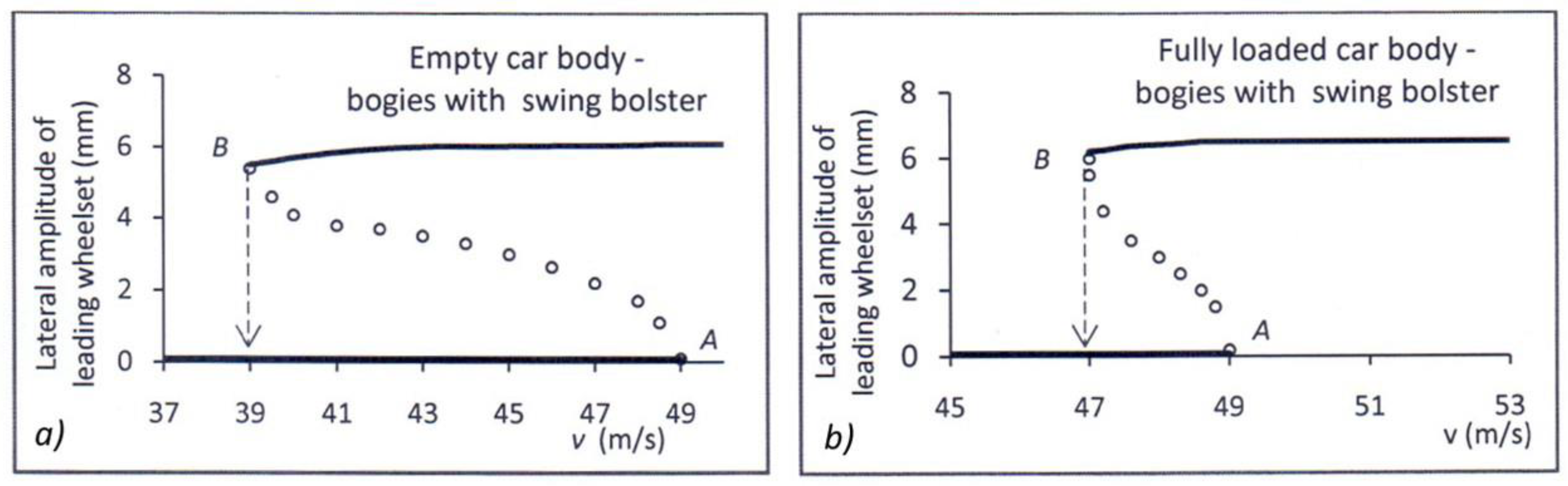
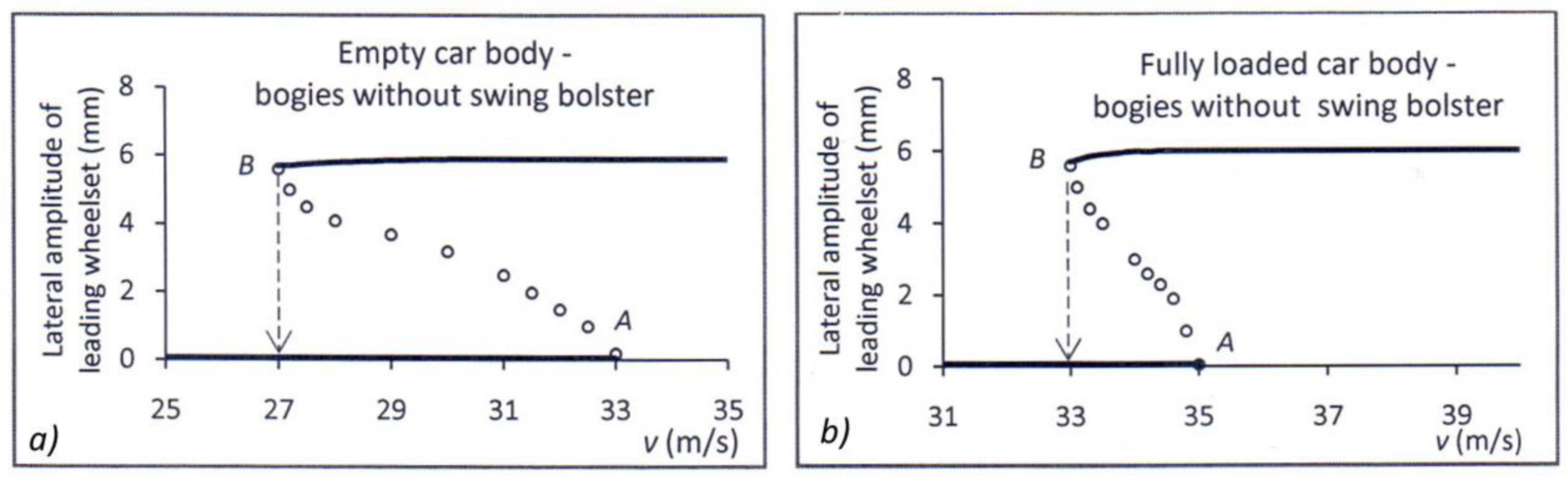
5.1. Results of Numerical Simulations on Straight Track

The movement of a wagon model was viewed as stable if the lateral oscillations of wheelsets decreased and vanished following discontinuation of the excitation, such as in the case presented in the Figure 6 for constant speed equal to 38 m/s. The motion instability of the wagon model was manifested by the occurrence of the limit cycle and for speeds equal to 39 m/s, as is illustrated in Figure 6. The lowest running speed, at which a limit cycle with constant amplitude appeared, was referred to as the critical speed.
To find the linear and nonlinear critical speeds of the moving wagon model, the amplitudes of lateral displacements of the leading wheelset in the first wagon bogie were observed. After a series of numerical calculations in the field of time, the bifurcation diagrams for leading wheelsets have been created as a function of wagon speed. In Figure 7 and Figure 8, the abscissa and ordinate represent the wagon speed and amplitude of the limit cycle, respectively. The solid lines denote the stable limit cycles, while dotted lines represent unstable limit cycles. For a certain range of speeds, the solutions can ‘jump’ between a stable damped motion and a limit cycle, which is affected by the excitation amplitude. This behavior is an example of a subcritical Hopf bifurcation and usually is present in non-linear railway vehicle dynamics.
In the presented diagrams, the A points define the linear critical speeds, while B are the turning points from a stable equilibrium to a periodic solution and the speeds at these points correspond to the nonlinear critical speeds of freight wagon model. Between nonlinear and linear critical speeds, two solutions exist: one stable solution without limit cycle and one with periodic limit cycle. Above the linear critical speed, a limit cycle occurs regardless of excitation amplitude. Numerical values of the discussed speeds are summarized in Table 1.
As a result of the study, it was found that the wagon model with bogies equipped with a swing bolster provides a sufficiently high nonlinear critical speed in straight track traffic. For an empty wagon, this speed was equal to 39 m/s (140.4 km/h), while for a fully loaded wagon it was 47 m/s (169.2 km/h). Further computational analyses were made, and it was also found that freight wagon model with bogies without swing bolsters would only be able to achieve comparable critical speeds on the straight track if the lateral and longitudinal stiffnesses of the primary suspension stage reached values of the order of 10,000 kN/m. However, as mentioned earlier, such stiffnesses would cause a huge deterioration in the dynamic properties of the freight wagon when moving on a curved track with a small radius of curvature.

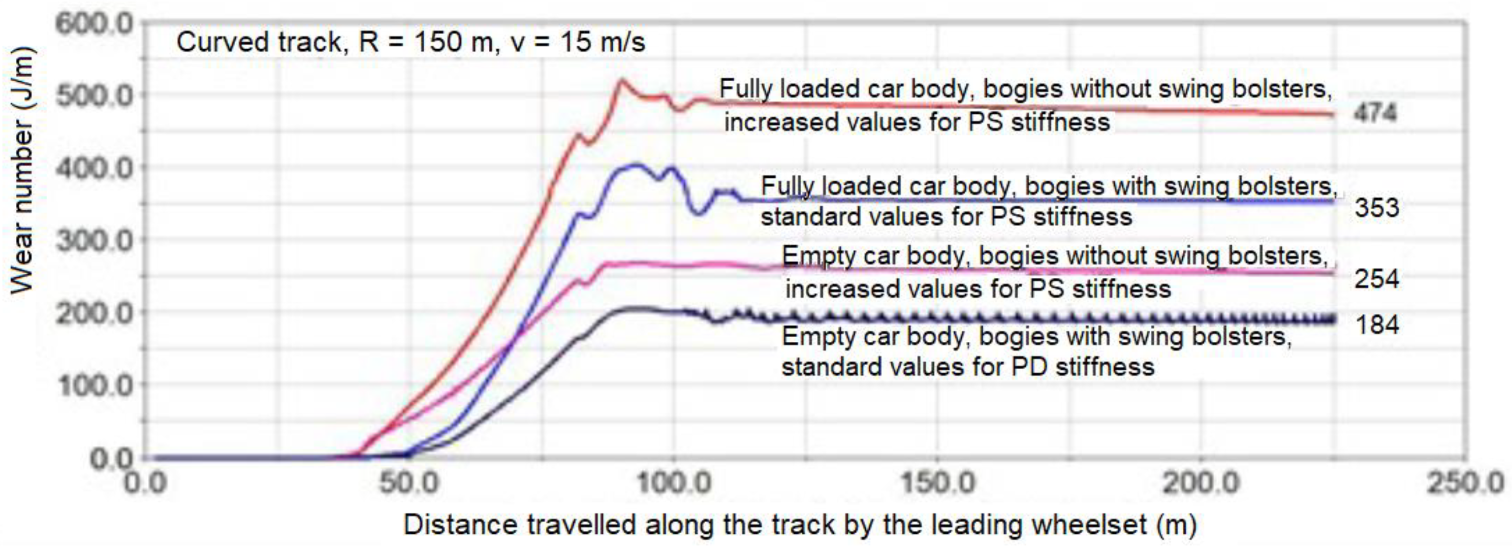
5.2. Wear Numbers for Wheels and Rails Obtained on a Curved Track with a Small Curve Radius

In Figure 9, the results concerning wear numbers of external wheels in a leading wheelset were shown in function of distance travelled along the curved track by the wagon models. The presented results of wheel–rail wear calculations on curved track concern two bogie design solutions, providing freight wagons on straight track with the critical speed of 169 km/h.
Table 2 presents values of the obtained wear numbers of external wheels in leading wheelset.
For wagons with an empty body, the wear number of the external wheels in the leading wheelset is about 27 percent less in a wagon with bogies equipped with a swing bolster compared to a wagon with bogies without a swing bolster. In the case of wagons with a fully loaded body, this difference is 25 percent in favor of the wagon with bogies with swing bolster.

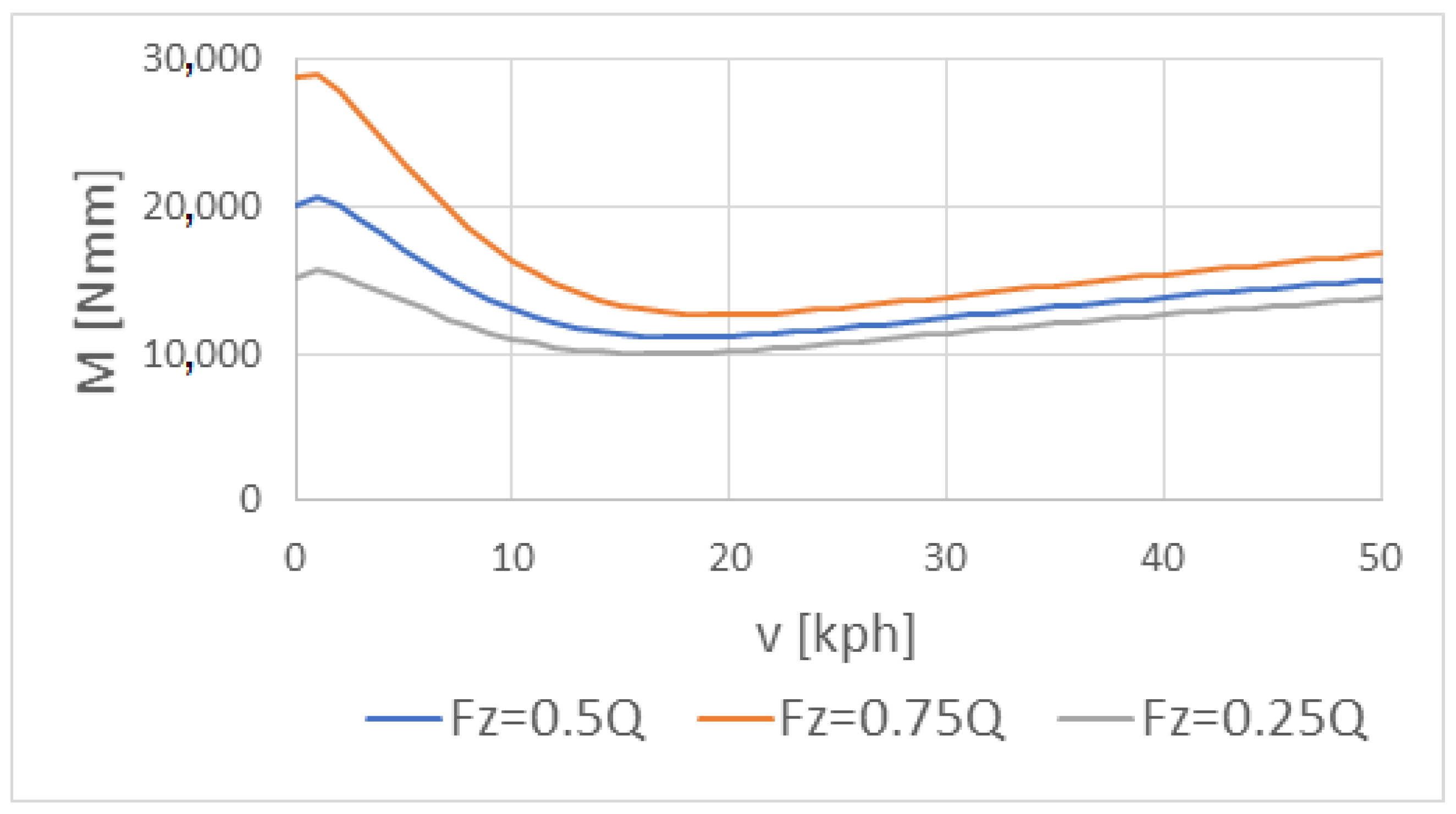
5.3. Results of Numerical Calculations of Friction in Bearing

The obtained values of the resistive torque versus wagon speed in the tapered roller bearing are presented in Figure 10, for the case of motion along the straight track ( F z = 0.5 Q ), and along the curved track for the wheel under overloading ( F z = 0.75 Q ) and under underloading ( F z = 0.25 Q ).
It is clearly seen that such resistive torque varied nonlinearly with wagon speed and reached its minimum for the wagon speed values between 15 and 20 kph. For the small wagon speed, the value of the resistive torque can be even three-fold higher than the minimum one. The wagon motion along the curve track can result in an increase of resistive torque values by 50% in case of the wheel under overloading and in their similar decrease in case of the wheel under underloading, respectively, compared to those obtained for the case of motion along straight track.
To be able to compare the resistive torque in different tapered roller bearings, we introduced a dimensionless indicator defined by Formula (29). This indicator can be treated as a comparative coefficient of friction. A similar approach to comparing the friction coefficient and the friction torque in rolling bearings tested with various methods and the use of a similar indicator are presented by Kanazawa et al. [51]:
I = M m i n 0.5 · d m · F z 2 + F y 2
where:
  • M m i n —minimum value of the resistive torque in taped roller bearing
For the rotational speed below 120 rpm, for various cases of loading the wheel this indicator reached values as presented in Table 3.
Interestingly, during studies presented in [52] for the shaft rotational speed in range 0–500 rpm, bearing lubricated by mineral oil, loading varied from 20–1140 N and mean diameter of bearing equal to 46 mm, values of such an indicator varied from 0.0047 to 0.022, so at least twice higher than these obtained from calculations. Interestingly, values of friction coefficient for the trust roller bearings lubricated with oil were also often twice higher than for the similar bearings lubricated with grease [51].

6. Conclusions

Simulation studies allowing evaluation of the validity of the use a swing bolster in the construction of two-axle freight bogies have been carried out.
The results of numerical calculations in the field of time revealed the presence of the subcritical Hopf bifurcation for leading wheelsets affected by a wagon speed in straight track traffic. A full loading of wagon model with bogies without swing bolster caused an increase of wagon critical speed by 22% compared to the case of empty wagon. The application of a swing bolster allowed the increasing of such a speed by 44% and reaching a sufficiently high nonlinear critical speed. Simultaneously, a full loading of such a wagon enhanced the wagon critical speed by 20%.
It was also found that a freight wagon model with bogies without swing bolsters could reach close values of a critical speed on the straight track when the lateral and longitudinal stiffnesses of the primary suspension stage reached values of the order of 10,000 kN/m. However, such strong stiffnesses could highly worsen the dynamic properties of the freight wagon when moving on a curved track with a small radius of curvature.
Results of numerical calculations of wear numbers W(n) in the wheel–rail contact patch revealed that the application of a swing bolster for empty wagons allowed decreasing of the wear number by 27% compared to the case of wagon without the swing bolster. In the case of wagons with the fully loaded bodies, this difference was 25 percent in favor of the wagon with bogies with a swing bolster.
The obtained values of the resistive torque in bearings of the assembly studied varied nonlinearly with wagon speed, reaching their minimum below 20 kph. During motion along the curve track, values of such a torque can be higher by 50% in case of the wheel under overloading and lower by 50% in case of the wheel under underloading, respectively, compared to those obtained during motion along straight track.
The existence of lateral vibrations of wheels can be beneficial for the displacements of debris and contaminations contained in bearing grease, which makes difficult the aggregation of such particles in bearing gaps. The effect of amplitude and frequency of lateral vibration on behavior of contaminations and debris inside roller bearings needs further study.

Author Contributions

Conceptualization, K.S.; methodology, K.S.; software, A.O. and M.W.; validation, P.K., A.R. and M.W.; formal analysis, A.R. and A.O.; investigation, M.W.; resources, M.W.; data curation, A.R.; writing—original draft preparation, K.S.; writing—review and editing, P.K. and A.O.; visualization, M.W.; supervision, A.R.; project administration, B.D.; funding acquisition, B.D. All authors have read and agreed to the published version of the manuscript.

Funding

This research received no external funding.

Institutional Review Board Statement

Not applicable.

Informed Consent Statement

Not applicable.

Data Availability Statement

Not applicable.

Conflicts of Interest

The authors declare no conflict of interest.

References

  1. Medwid, M.; Stawecki, W.; Czerwinsk, J. Bimodal rolling stock as the economically justified alternative to the existing combined transport systems. Pojazdy Szyn. 2016, 2, 1–8. [Google Scholar]
  2. Reddy, V.; Chattopadhyay, G.; Hargreaves, D. Analysis of Rail Wear Data for Evaluation of Lubrication Performance. Cquniversity. Conference Contribution. 2006. Available online: https://hdl.handle.net/10018/42614 (accessed on 2 December 2021).
  3. Chen, G. Friction-Induced Vibration of a Railway Wheelset-Track System and Its Effect on Rail Corrugation. Lubricants 2020, 8, 18. [Google Scholar] [CrossRef] [Green Version]
  4. Khan, S.A.; Persson, I.; Lundberg, J.; Stenström, C. Prediction of the effects of friction control on top-of-rail cracks. Proc. Inst. Mech. Eng. Part F J. Rail Rapid Transit 2016, 232, 484–494. [Google Scholar] [CrossRef] [Green Version]
  5. Trummer, G.; Lee, Z.S.; Lewis, R.; Six, K. Modelling of Frictional Conditions in the Wheel–Rail Interface Due to Application of Top-of-Rail Products. Lubricants 2021, 9, 100. [Google Scholar] [CrossRef]
  6. Eadie, D.T.; Vidler, B.; Hooper, N.E.; Makowsky, T. Top of rail friction control: Lateral force and rail wear reduction in a freight application. In Proceedings of the International Heavy Haul Association Conference, Fort Worth, TX, USA, 5–9 May 2003; pp. 573–581. [Google Scholar]
  7. Lundberg, J.; Rantatalo, M.; Wanhainen, C.; Casselgren, J. Measurements of friction coefficients be-tween rails lubricated with a friction modifier and the wheels of an IORE locomotive during real working conditions. Wear 2015, 324–325, 109–117. [Google Scholar] [CrossRef] [Green Version]
  8. Gallardo-Hernandez, E.A.; Lewis, R. Twin disc assessment of wheel/rail adhesion. Wear 2008, 265, 1309–1316. [Google Scholar] [CrossRef] [Green Version]
  9. Lemma, Y.; Rantatalo, M.; Lundberg, J. Top-of-Rail Friction Measurements of the Swedish Iron Ore Line. In Proceedings of the 3rd international workshop and Congress on eMaintenance, Lulea, Sweden, 17–18 June 2014. [Google Scholar]
  10. Products for Railway Applications. Schaeffler Group Industrial. 2010. Available online: https://www.schaeffler.com/remotemedien/media/_shared_media/08_media_library/01_publications/schaeffler_2/tpi/downloads_8/tpi_158_de_en.pdf (accessed on 2 December 2021).
  11. Railways. NSK Ltd. 2021. Available online: https://www.nsk.com/industries/railways.html (accessed on 2 December 2021).
  12. Railway Technical Handbook. Vol. 1. Axleboxes, Wheelset Bearings, Sensors, Condition Monitoring, Subsystems and Services. SKF Group. 2011. Available online: https://www.skf.com/binaries/pub12/Images/0901d196801410ca-10987_2-EN_tcm_12-503040.pdf (accessed on 2 December 2021).
  13. Iwnicki, S. Handbook of Railway Vehicle Dynamics; CRC Press: Boca Raton, FL, USA, 2006. [Google Scholar]
  14. Fernandes, H.M.G. Analysis of Failures of Rolling Stock Railways Rolling Bearings. Master’s Thesis, Faculty of Engineering of the University of Porto, Porto, Portugal, 2017. [Google Scholar]
  15. EN 12081:2017 Railway Applications—Axleboxes—Lubricating Greases. Available online: https://www.nlfnorm.cz/en/ehn/5841 (accessed on 2 December 2021).
  16. Cyriac, F.; Lugt, P.M.; Bosman, R. Yield Stress and Low-Temperature Start-Up Torque of Lubricating Greases. Tribol. Lett. 2016, 63, 6. [Google Scholar] [CrossRef] [Green Version]
  17. Grease Lubrication for Railway Axlebox Bearings. Evol. SKF Technol. Mag. 2007, 7. Available online: https://evolution.skf.com/grease-lubrication-for-railway-axlebox-bearings/ (accessed on 2 December 2021).
  18. Lundberg, J.; Aditya, P.; Söderholm, P. Running temperature and mechanical stability of grease as maintenance parameters of railway bearings. Int. J. Autom. Comput. 2010, 7, 160–166. [Google Scholar] [CrossRef]
  19. Bosman, R.; Lugt, P.M. The Microstructure of Calcium Sulfonate Complex Lubricating Grease and Its Change in the Presence of Water. Tribol. Trans. 2018, 61, 842–849. [Google Scholar] [CrossRef] [Green Version]
  20. He, Q.; Li, A.; Guo, Y.; Liu, S.; Kong, L.-H. Effect of nanometer silicon dioxide on the frictional behavior of lubricating grease. Nanomater. Nanotechnol. 2017, 7, 1–9. [Google Scholar] [CrossRef] [Green Version]
  21. Hu, E.Z.; Xu, Y.; Hu, K.H.; Hu, X.G. Tribological properties of 3 types of MoS2 additives in different base greases. Lubr. Sci. 2017, 29, 541–555. [Google Scholar] [CrossRef]
  22. Zheng, B.; Zhou, J.; Jia, X.; He, Q. Friction and wear property of lithium grease contained with copper oxide nanoparticles. Appl. Nanosci. 2019, 10, 1355–1367. [Google Scholar] [CrossRef]
  23. Mohamed, A.; Ali, S.; Osman, T.A.; Kamel, B.M. Development and manufacturing an automated lubrication machine test for nano grease. J. Mater. Res. Technol. 2020, 9, 2054–2062. [Google Scholar] [CrossRef]
  24. Casado, J.E.; González, A.F.; Huerga, Á.J.D.R.; Rodríguez-Solla, H.; Díaz-García, M.E.; Badía-Laíño, R. Unctuous ZrO2 nanoparticles with improved functional attributes as lubricant additives. IOP Publ. Nanotechnol. 2017, 28, 495704. [Google Scholar] [CrossRef] [PubMed]
  25. Rylski, A.; Siczek, K. The Effect of Addition of Nanoparticles, Especially ZrO2-Based, on Tribological Behavior of Lubricants. Lubricants 2020, 8, 23. [Google Scholar] [CrossRef] [Green Version]
  26. Pape, F.; Poll, G. Investigations on Graphene Platelets as Dry Lubricant and as Grease Additive for Sliding Contacts and Rolling Bearing Application. Lubricants 2020, 8, 3. [Google Scholar] [CrossRef] [Green Version]
  27. Yamanaka, H.; Zenbutsu, M. Development of Tapered Roller Bearings for Electric/Hybrid Vehicles, NSK Technical Journal Motion & Control 32, 2021, 1–6. Available online: https://www.nsk.com/rd/pdf/techJournal/etj-0032.pdf (accessed on 2 December 2021).
  28. Zhang, C.; Gu, L.; Mao, Y.; Wang, L. Modeling the frictional torque of a dry-lubricated tapered roller bearing considering the roller skewing. Friction 2019, 7, 551–563. [Google Scholar] [CrossRef] [Green Version]
  29. Gupta, P.K. On the Dynamics of a Tapered Roller Bearing. ASME J. Tribol. 1989, 111, 278–287. [Google Scholar] [CrossRef]
  30. Schwarz, V.A. Experimental studies of the thermal behaviour of a tapered roller bearing assembly. In Proceedings of the 11th Brazilian Congress of Thermal Sciences and Engineering ENCIT, Curitiba, Brazil, 5–8 December 2006. [Google Scholar]
  31. Witte, D.C. Operating torque of tapered roller bearings. ASLE Trans. 1973, 16, 61–67. [Google Scholar] [CrossRef]
  32. Aihara, S. A new running torque formula for tapered roller bearings under axial load. J. Tribol. 1987, 109, 471–477. [Google Scholar] [CrossRef]
  33. Zhou, R.S.; Hoeprich, M.R. Torque of tapered roller bearings. J. Tribol. 1991, 113, 590–597. [Google Scholar] [CrossRef]
  34. Yan, K.; Wang, N.; Zhai, Q.; Zhu, Y.; Zhang, J.; Niu, Q. Theoretical and experimental investigation on the thermal characteristics of double-row tapered roller bearings of high speed locomotive. Int. J. Heat Mass Transf. 2015, 84, 1119–1130. [Google Scholar] [CrossRef]
  35. Monograph on ICF. All-Coil Coaches. Indian Railw. Inst. Civ. Eng. (IRICEN) Monogr. 2016, 1, 411001. Available online: https://www.iricen.gov.in/iricen/books_jquery/Monograph%20on%20ICF.pdf (accessed on 2 December 2021).
  36. MAXBE_D2.1a) Axle Bearings Failure Modes and Degradation Process. Available online: https://web.fe.up.pt/~maxbe/maxbe_wps.html (accessed on 9 February 2022).
  37. VI-Grade Engineering Software and Services. VI Rail 15.0 Documentation. 2019. Available online: https://www.vi-grade.com/dynatc/releasenotes-0189-4a93/VI_Automotive_19_0_Release_Notes.pdf (accessed on 2 December 2021).
  38. Kalker, J.J. Three-Dimensional Elastic Bodies in Rolling Contact. In Solid Mechanics and Its Applications; Springer: Dordrecht, The Netherlands; Boston, MA, USA; London, UK, 1990. [Google Scholar]
  39. Piotrowski, J.; Kik, W. A simplified model of wheel/rail contact mechanics for non-hertzian problems and its application in rail vehicle dynamic simulations. Veh. Syst. Dyn. 2008, 46, 27–48. [Google Scholar] [CrossRef]
  40. Kisilowski, J.; Knothe, K. Advanced Railway Vehicle System Dynamics; WNT: Warszawa, Poland, 1991. [Google Scholar]
  41. Iwnicki, S. Manchester Benchmarks for Rail Vehicle Simulation. Veh. Syst. Dyn. 1998, 30, 295–313. [Google Scholar] [CrossRef]
  42. EN 14363:2016; Railway Applications. Testing and Simulation for the Acceptance of Running Characteristics of Railway Vehicles. Running Behaviour and Stationary Tests. Comite Europeen de Normalisation: Brussels, Belgium, 2016.
  43. Jendel, T.; Berg, M. Prediction of Wheel Profile Wear. Veh. Syst. Dyn. 2002, 37 (Suppl. 1), 502–513. [Google Scholar] [CrossRef]
  44. Matej, J. Modeling and computer simulations of bimodal cars from the point of view of their proneness to derailment. Pr. Nauk. Politech. Warszawskiej. Mech. 2010, 234, 3–132. [Google Scholar]
  45. Elkins, J.A.; Carter, A. Testing and Analysis Techniques for Safety Assessment of Rail Vehicles. Veh. Syst. Dyn. 1993, 2, 185–208. [Google Scholar] [CrossRef]
  46. Nagase, K.; Wakabayashi, Y.; Sakahara, H. A study of the phenomenon of wheel climb derailment: Results of basic experiments using model bogies. IMechE Part F J. Rail Rapid Transit 2002, 216, 237–247. [Google Scholar] [CrossRef]
  47. Shu, X.; Wilson, N.; Wu, H.; Tunna, J. A bi-parameter distance criterion for flange climb derailment. In Proceedings of the ASME/IEEE Joint Rail Conference, Pueblo, CO, USA, 16–18 March 2005; pp. 9–17. [Google Scholar]
  48. Wu, H.; Shu, X.; Wilson, N. Flange Climb Derailment Criteria and Wheel/Rail Profile Management and Maintenance Guidelines for Transit Operations; TCRP Report 71; Transportation Technology Center, Inc.: Pueblo, CO, USA, 2005. [Google Scholar]
  49. Zeng, J.; Guan, Q.H. Study on flange climb derailment criteria of a railway wheelset. Veh. Syst. Dyn. 2008, 46, 239–251. [Google Scholar] [CrossRef]
  50. The SKF Model for Calculating the Frictional Moment. SKF, 2021, 1–15. Available online: https://www.skf.com/binaries/pub12/Images/0901d1968065e9e7-The-SKF-model-for-calculating-the-frictional-moment_tcm_12-299767.pdf (accessed on 2 December 2021).
  51. Kanazawa, Y.; de Laurentis, N.; Kadiric, A. Studies of Friction in Grease-Lubricated Rolling Bearings Using Ball-on-Disc and Full Bearing Tests. Tribol. Trans. 2020, 63, 77–89. [Google Scholar]
  52. Bercea, I.; Mita, N.; Damian, I.; Bercea, M.; Cretu, S. A Theoretical and Experimental Study on Friction Losses in a Tapered Roller Bearing. Tibology Ind. 1996, 18, 19–23. [Google Scholar]
Figure 1. Scheme of a semi-trailer road tractor as a wagon body in the structure of bimodal freight wagon (based on the concept described in [1]); 1—semitrailer seats supported/attached to bimodal bogies, 2—bimodal semitrailer, 3—semitrailer frame.
Lubricants 10 00026 g001
Figure 2. End bogies of a bi-modal freight wagon: (a) with swing bolster; (b) without swing bolster; 1—bogie frame, 2—rocking beam, 3—nest of central pivot, 4—adapter, 5—torque arm, 6—coupling device.
Lubricants 10 00026 g002
Figure 3. Car body support on freight bogies equipped with swing bolsters suspension: (a) scheme in cross-section; (b) photo of the prototype of the Polish bimodal wagon.
Lubricants 10 00026 g003
Figure 4. Side friction block with swing bolsters suspension: (a) scheme in cross-section, 1—side slide body, 2—spring, 3—wear plate guide, 4—steel wear plate, 5—steel roller; (b) photo of the prototype of the Polish bimodal wagon.
Lubricants 10 00026 g004
Figure 5. Primary suspension of the bogie: (a) scheme of wheelset axle guidance in the bogie frame; (b) vertical stiffness characteristics of suspension.
Lubricants 10 00026 g005
Figure 6. Time history of wheelset lateral movements following a single lateral excitation at wagon speed equal to 38 m/s and 39 m/s.
Lubricants 10 00026 g006
Figure 7. Bifurcation diagrams of leading wheelset behavior in bogies with swing bolster after an excitation for: (a) empty and (b) fully loaded car body.
Lubricants 10 00026 g007
Figure 8. Bifurcation diagrams of leading wheelset behavior in bogies equipped without swing bolster after an excitation for (a) empty and (b) fully loaded car body.
Lubricants 10 00026 g008
Figure 9. Numbers of an external wheels in a leading wheelset in function of distance along the curved track with a full arc radius equal to 150 m.
Lubricants 10 00026 g009
Figure 10. The resistive torque M in the tapered roller bearing versus wagon speed v , for the case of motion along the straight track ( F z = 0.5 Q ), and along the curved track for the wheel under overloading (( F z = 0.75 Q ) and under underloading ( F z = 0.25 Q ).
Lubricants 10 00026 g010
Table 1. Values of critical speeds.
CaseCritical Speeds (m/s)
Empty car body, bogies without swing bolster27/33
Fully loaded wagon, bogie without swing bolster33/35
Empty car body, bogies with swing bolster39/49
Fully loaded wagon, bogies with swing bolster47/49
Table 2. The obtained wear number of the external wheels in leading wheelset.
Bogie with Swing BolsterBogie without Swing Bolster
Standard stiffness
for primary suspension data
Increased stiffness
for primary suspension
Empty
wagon body
Fully loaded
wagon body
Empty
wagon body
Fully loaded
wagon body
Wear numbers (J/m)Wear numbers (J/m)
184353254474
Table 3. The obtained values of the dimensionless indicator I .
Wheel Loading Case I [–]
F z = 0.5 Q
F z = 0.75 Q
0.0018
0.0014
F z = 0.25 Q Nadal criterion0.0029
Weinstock criterion0.0024
Matej criterion0.0027
Publisher’s Note: MDPI stays neutral with regard to jurisdictional claims in published maps and institutional affiliations.

