
Tribological Behavior of Reinforced PTFE Composites and Un-Reinforced Polyketone-Based Materials against Coated Steel

 ,
,  ,
, 
Abstract
:1. Introduction
2. Experimental
2.1. Materials
2.2. Pin-on-Disc Sliding Wear Tests
3. Results and Discussion
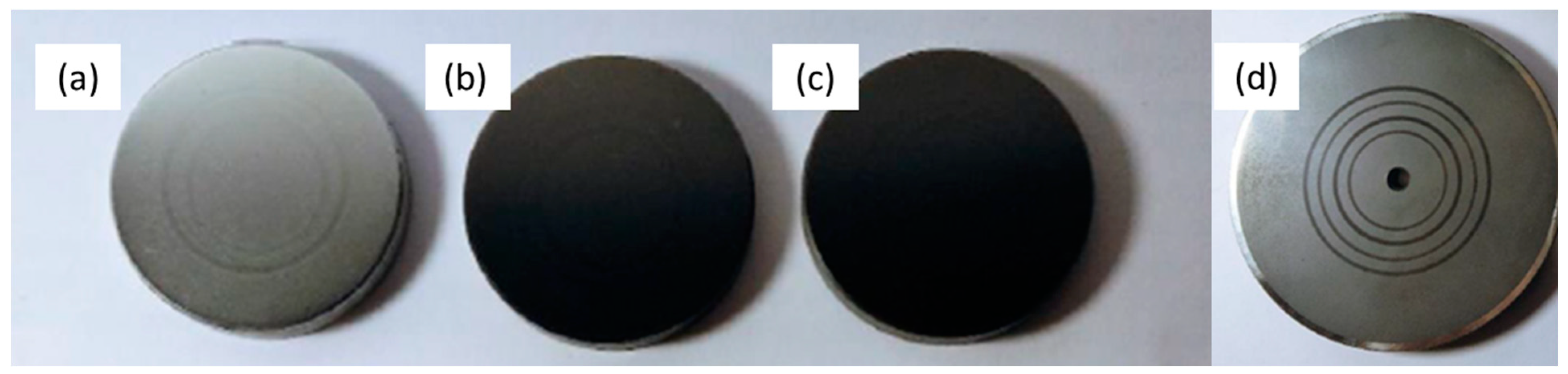
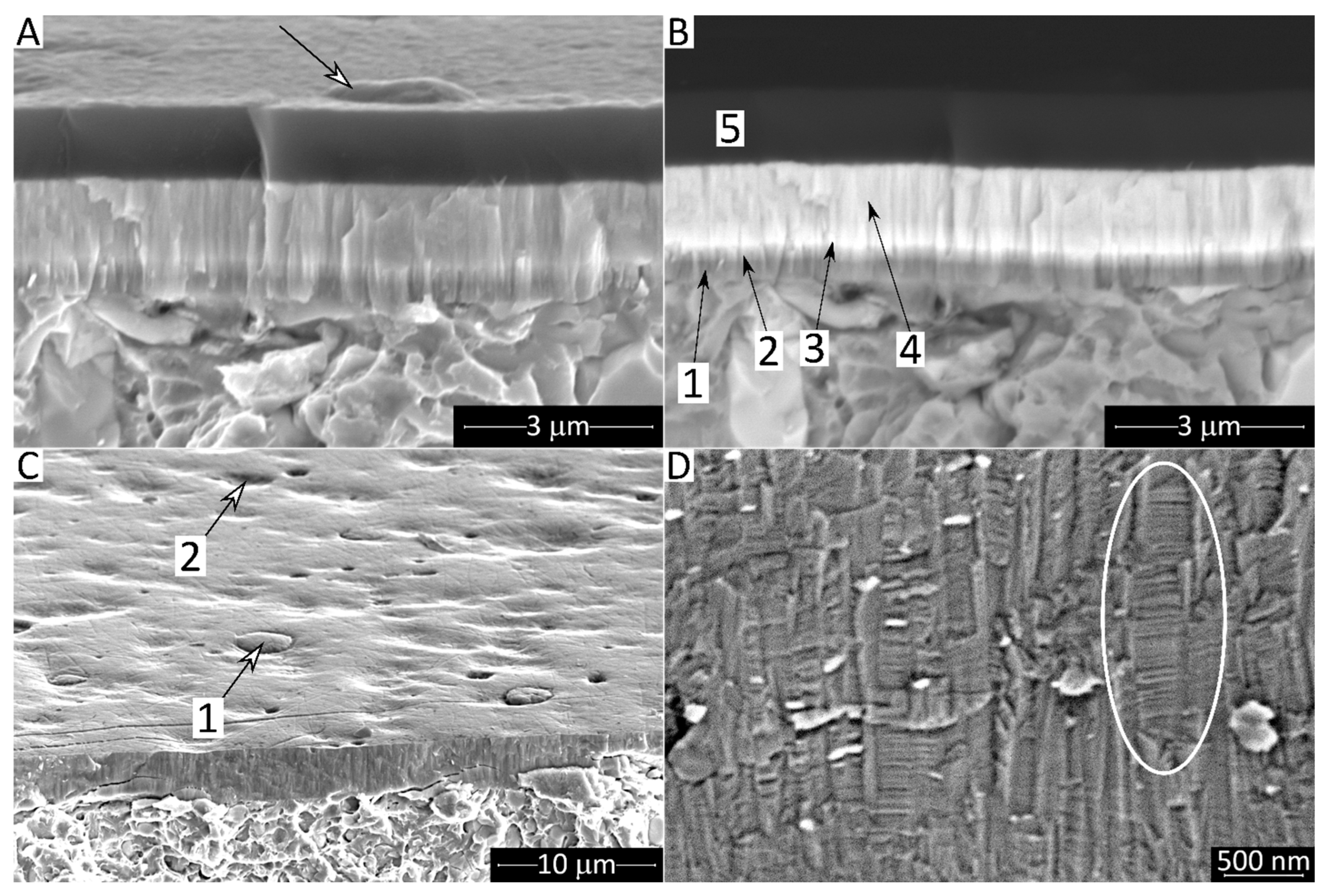
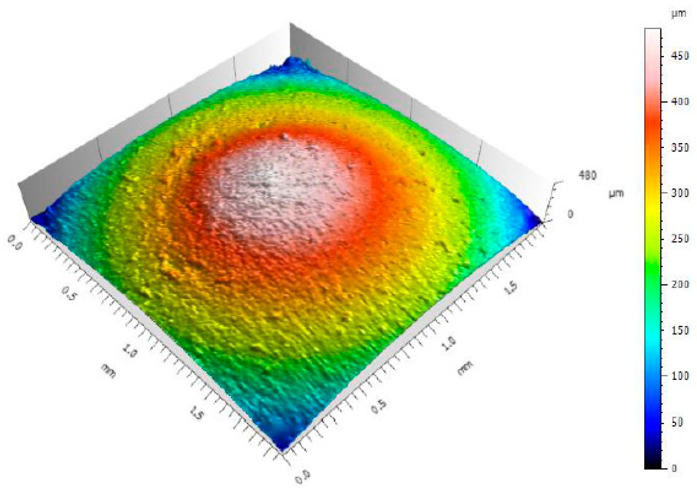
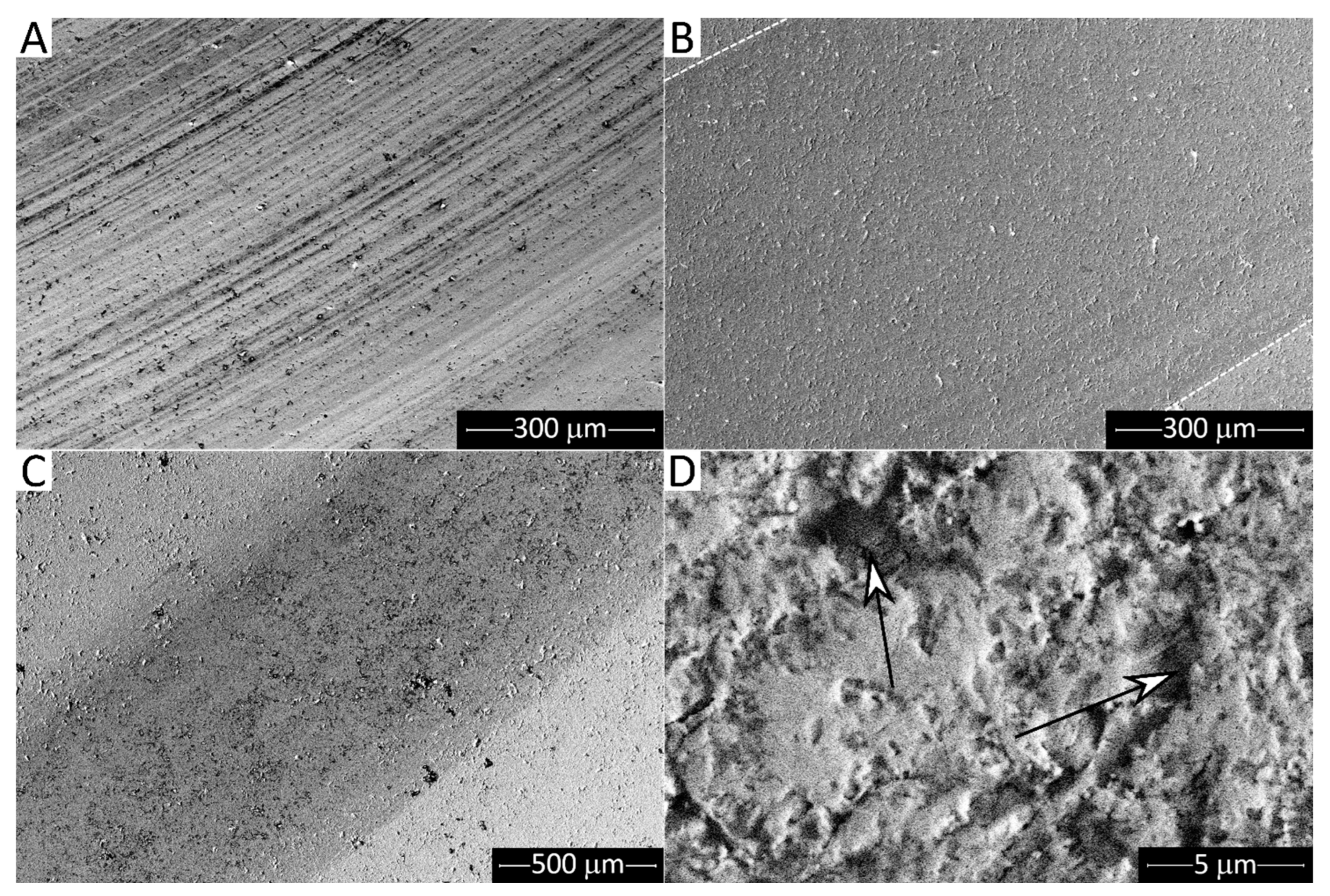
3.1. Microstructure and Topography of Pins and Countersurface Materials
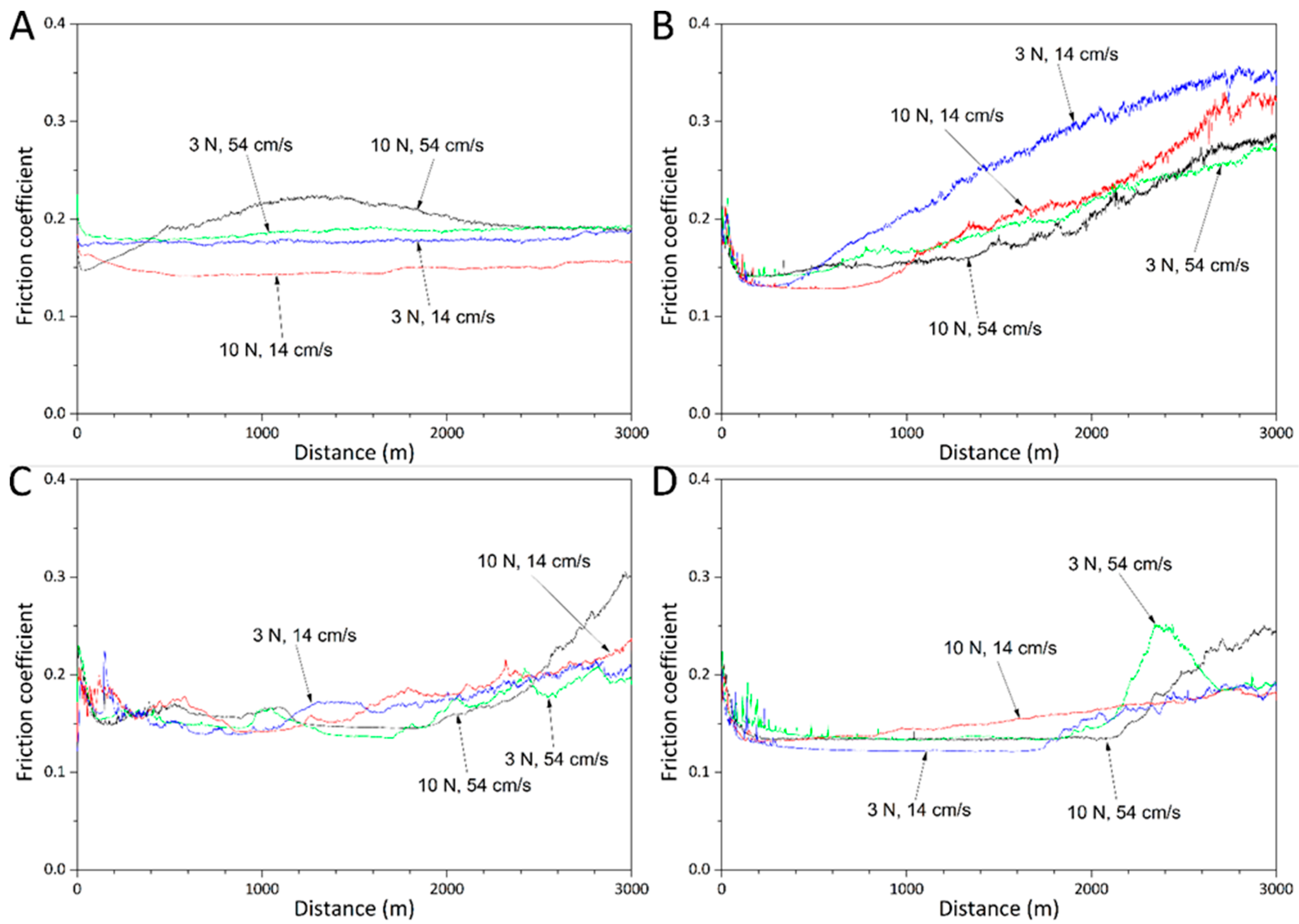
3.2. Sliding Wear Behaviour
3.2.1. Syntek 439
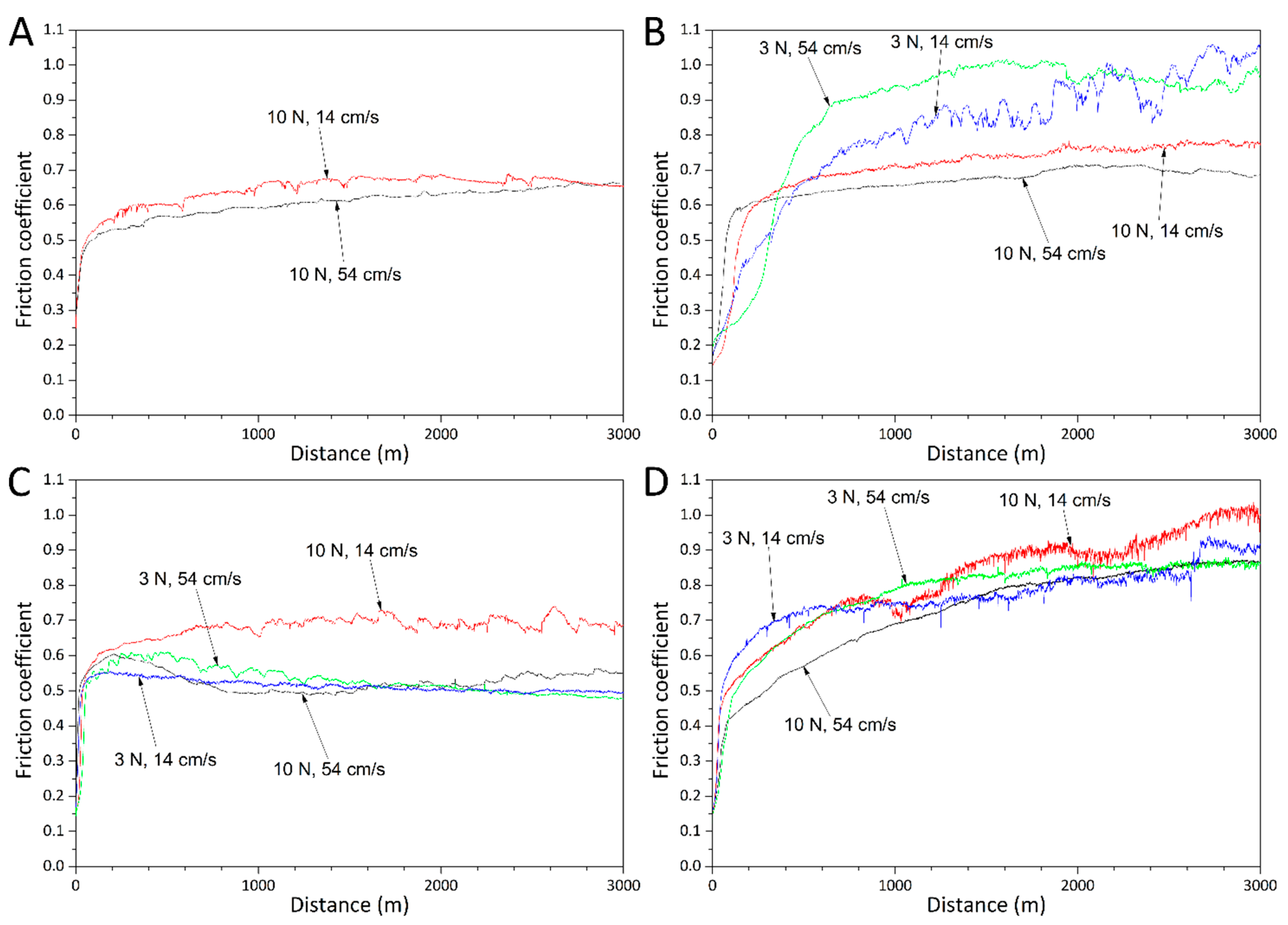
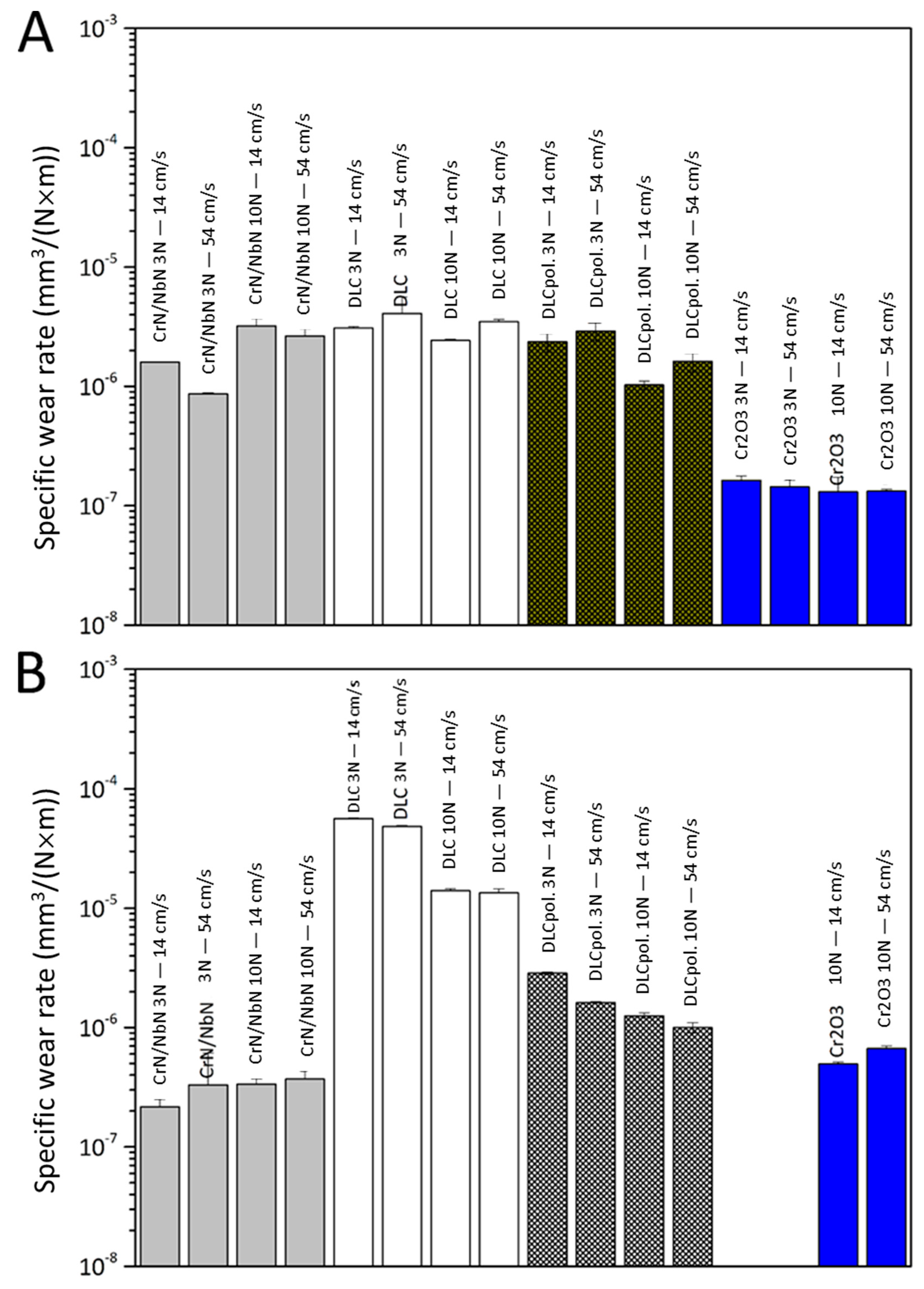
Friction Trends and Specific Wear Rates
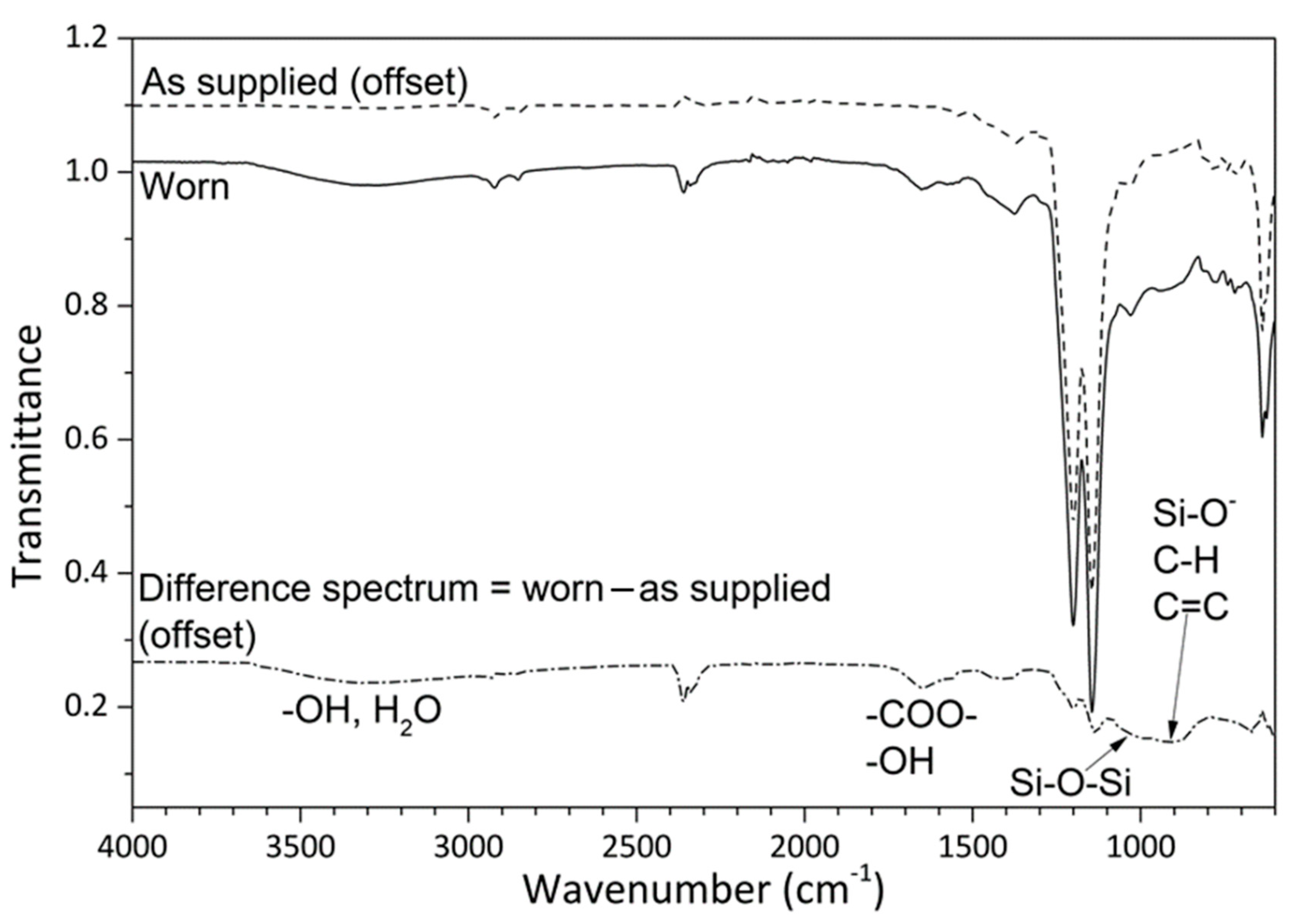
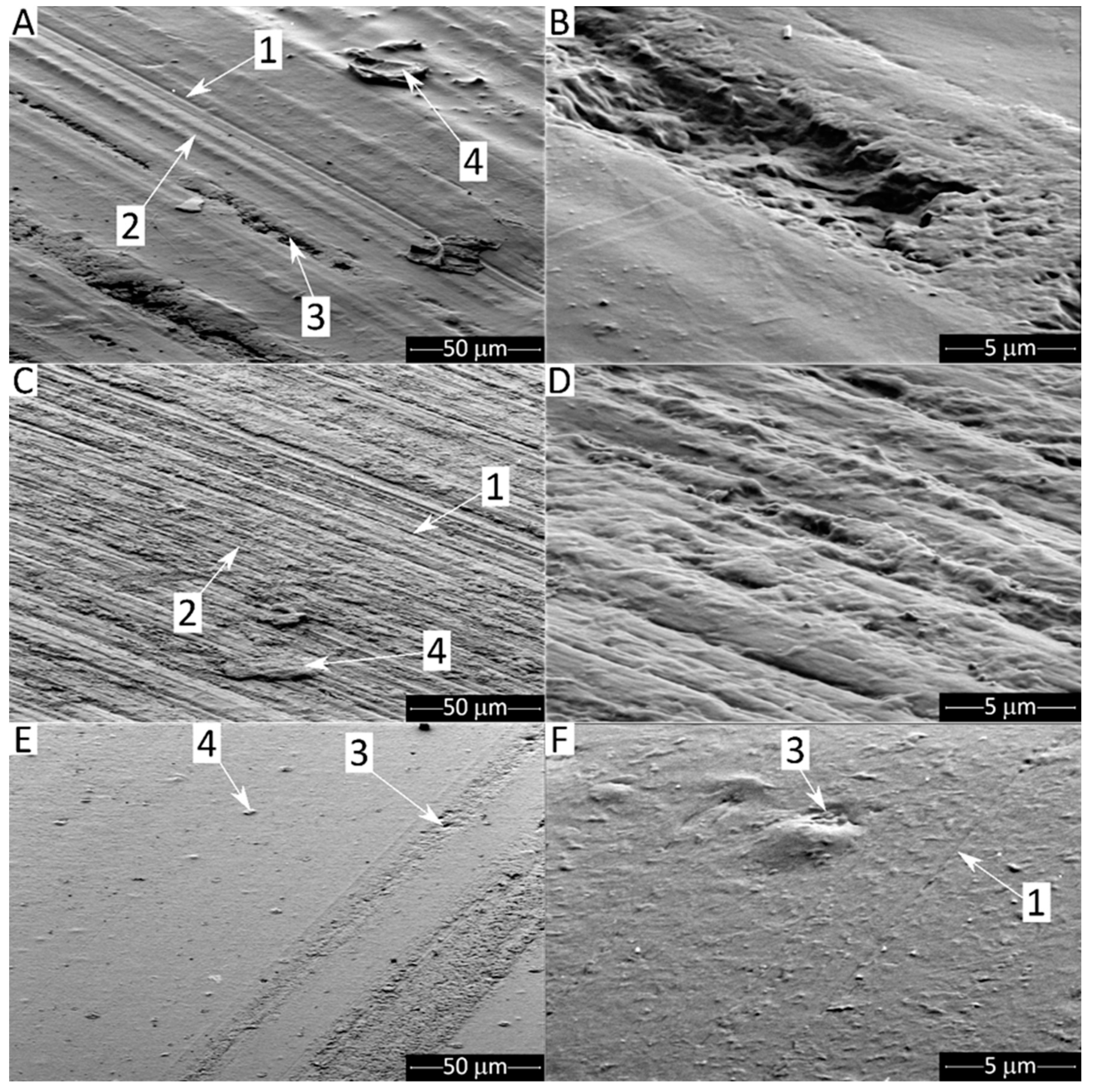
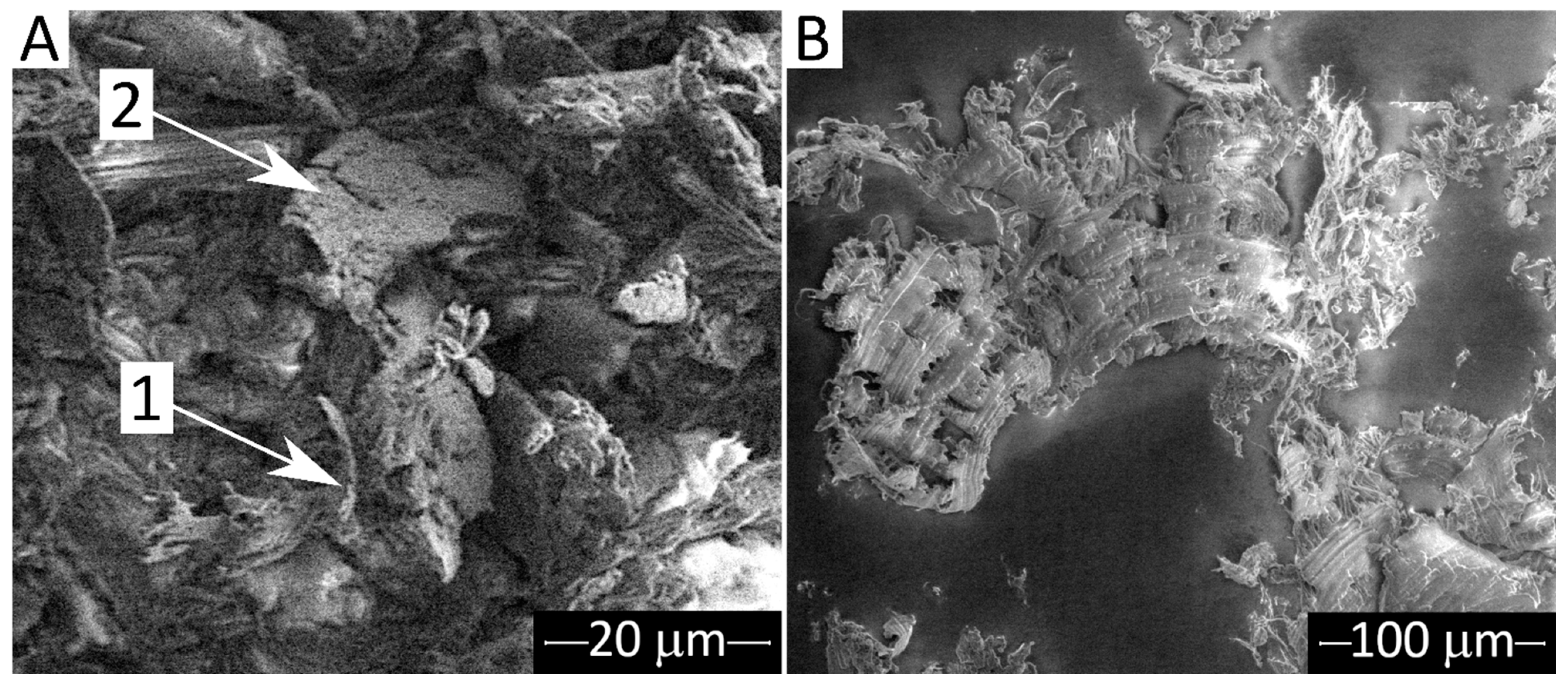
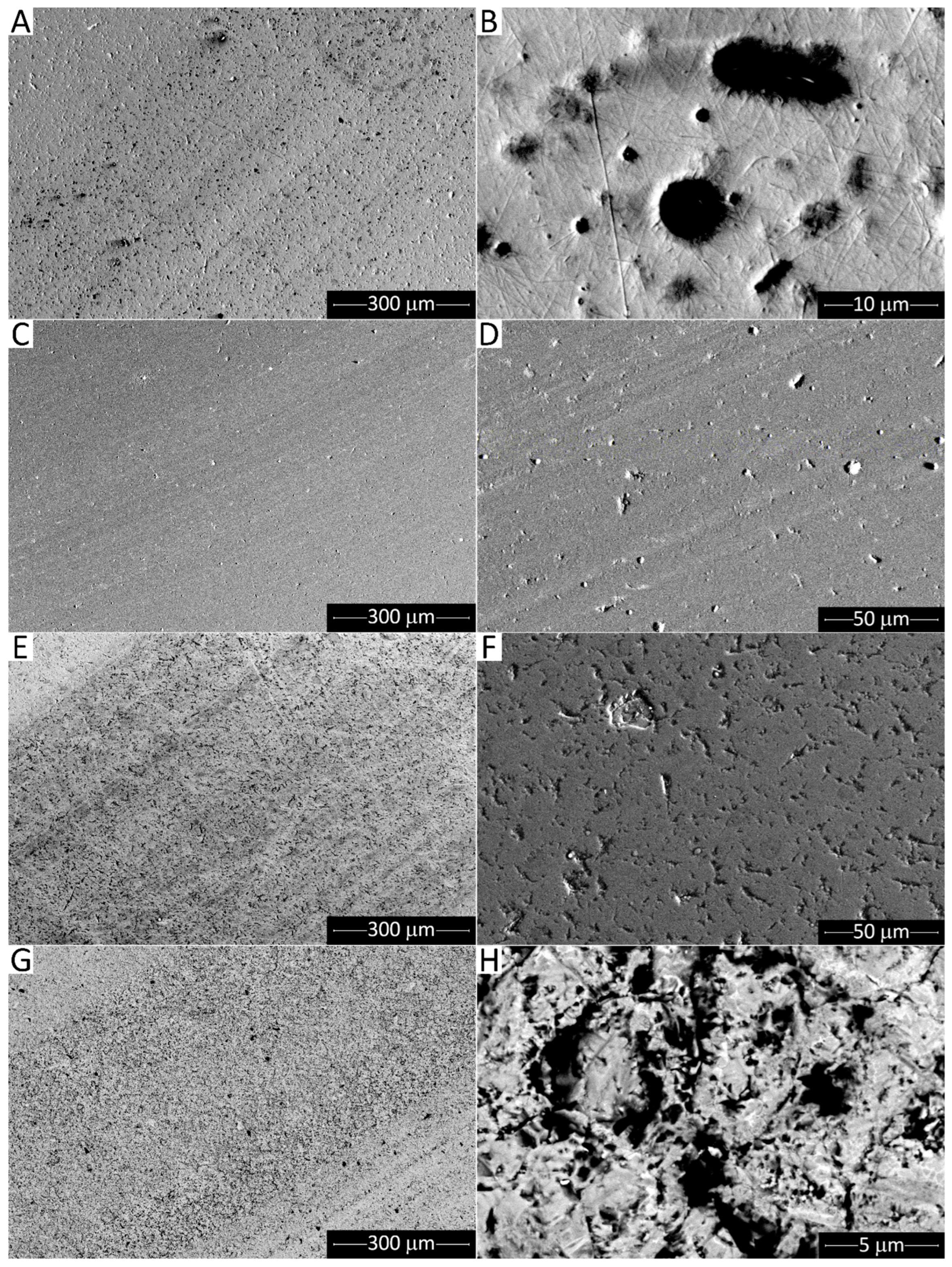
Analysis and Discussion of Wear Mechanisms
3.2.2. Syntek PKE
Friction Trends and Specific Wear Rates
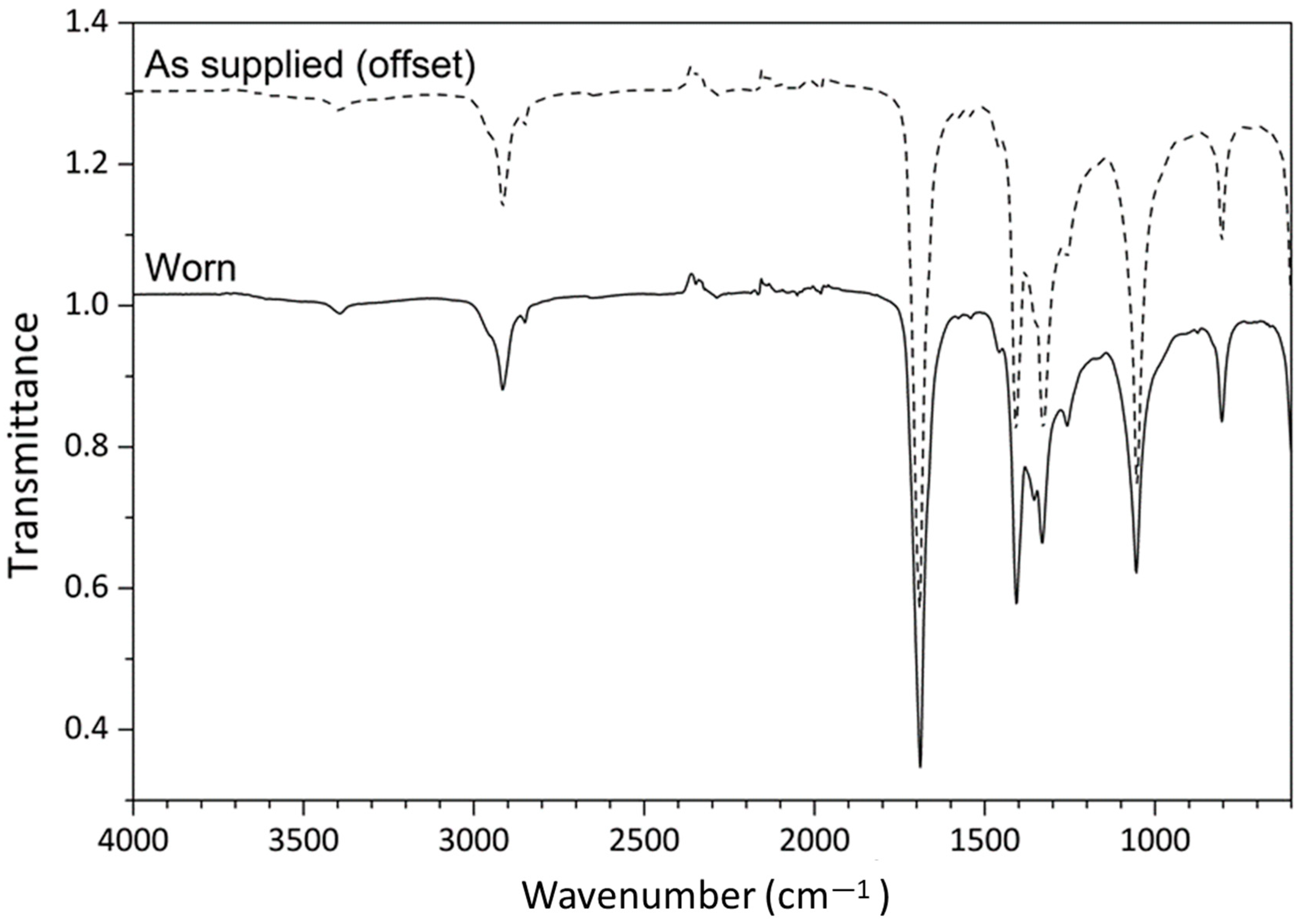
Analysis and Discussion of Wear Mechanisms
4. Conclusions
Author Contributions
Funding
Institutional Review Board Statement
Informed Consent Statement
Data Availability Statement
Conflicts of Interest
References
- Ashby, M. The CES EduPack Resource Booklet 2—Material and Process Charts; Cambridge University: Cambridge, UK, 2009. [Google Scholar]
- Fox, M. Polymer Tribology. Lube Mag. 2016, 135, 32–37. [Google Scholar]
- Bhushan, B. Principles and Applications of Tribology, 2nd ed.; John Wiley & Sons Ltd.: Chichester, UK, 2013; ISBN 978-1-119-94454-6. [Google Scholar]
- Straffelini, G. Materials for Tribology. In Friction and Wear-Methodologies for Design and Control; Springer International Publishing: Cham, Switzerland, 2015; pp. 159–199. [Google Scholar]
- Straffelini, G. Surfaces in Contact. In Friction and Wear-Methodologies for Design and Control; Springer Tracts in Mechanical Engineering; Springer International Publishing: Cham, Switzerland, 2015; pp. 1–20. [Google Scholar]
- Stachowiak, G.W.; Batchelor, A.W. Wear of Non-Metallic Materials. In Engineering Tribology; Elsevier: Burlington, MA, USA, 2014; pp. 679–734. ISBN 978-0-12-397047-3. [Google Scholar]
- Biswas, S.K.; Vijayan, K. Friction and wear of PTFE—A review. Wear 1992, 158, 193–211. [Google Scholar] [CrossRef]
- Blanchet, T.A. Wear of Polytetrafluoroethylene and PTFE composites. In Polymer Tribology; Sinha, S.K., Briscoe, B.J., Eds.; Imperial College Press: London, UK, 2009; pp. 347–374. ISBN 978-1-84816-202-0. [Google Scholar]
- Friedrich, K. Polymer composites for tribological applications. Adv. Ind. Eng. Polym. Res. 2018, 1, 3–39. [Google Scholar] [CrossRef]
- Song, F.; Wang, Q.; Wang, T. Effects of glass fiber and molybdenum disulfide on tribological behaviors and PV limit of chopped carbon fiber reinforced Polytetrafluoroethylene composites. Tribol. Int. 2016, 104, 392–401. [Google Scholar] [CrossRef]
- Vasilev, A.P.; Okhlopkova, A.A.; Struchkova, T.S.; Grakovich, P.N.; Bashlakova, A.L. Investigation of the Influence of Complex Fillers on the Properties and Structure of Polytetrafluoroethylene. J. Frict. Wear 2018, 39, 427–432. [Google Scholar] [CrossRef]
- Zhang, F.; Zhang, J.; Zhu, Y.; Wang, X.; Jin, Y. Microstructure and Properties of Polytetrafluoroethylene Composites Modified by Carbon Materials and Aramid Fibers. Coatings 2020, 10, 1103. [Google Scholar] [CrossRef]
- Fan, X.; Li, G.; Guo, Y.; Zhang, L.; Xu, Y.; Zhao, F.; Zhang, G. Role of reinforcement types and silica nanoparticles on tribofilm growth at PTFE-Steel interface. Tribol. Int. 2020, 143, 106035. [Google Scholar] [CrossRef]
- Conte, M.; Igartua, A. Study of PTFE composites tribological behavior. Wear 2012, 296, 568–574. [Google Scholar] [CrossRef]
- Khedkar, J.; Negulescu, I.; Meletis, E.I. Sliding wear behavior of PTFE composites. Wear 2002, 252, 361–369. [Google Scholar] [CrossRef]
- Ye, P.; Wu, J.; Mu, L.; He, D.; Feng, X.; Lu, X. Tribological behaviors of carbon series additions reinforced CF/PTFE composites at high speed. J. Appl. Polym. Sci. 2016, 133, 43236. [Google Scholar] [CrossRef]
- Drent, E.; Mul, W.P.; Smaardijk, A.A. Polyketones. In Encyclopedia of Polymer Science and Technology; Wiley: Chichester, UK, 2003. [Google Scholar]
- Unal, H.; Sen, U.; Mimaroglu, A. Dry sliding wear characteristics of some industrial polymers against steel counterface. Tribol. Int. 2004, 37, 727–732. [Google Scholar] [CrossRef]
- Zhang, G.; Wetzel, B.; Jim, B.; Oesterle, W. Impact of counterface topography on the formation mechanisms of nanostructured tribofilm of PEEK hybrid nanocomposites. Tribol. Int. 2015, 83, 156–165. [Google Scholar] [CrossRef]
- Bahadur, S.; Schwartz, C. Mechanical and Tribological Behavior of Polymers Filled with Particulate Fillers. In Polymer Tribology; Sinha, S.K., Briscoe, B.J., Eds.; Imperial College Press: London, UK, 2009; pp. 416–448. [Google Scholar]
- Ye, J.; Tao, B.; Sun, W.; Haidar, D.R.; Alam, K.I.; Liu, K.; Burris, D.L. The Competing Effects of Counterface Peaks and Valleys on the Wear and Transfer of Ultra-Low Wear Alumina–PTFE. Tribol. Lett. 2018, 66, 12. [Google Scholar] [CrossRef]
- Friedrich, K.; Karger-Kocsis, J.; Lu, Z. Effects of steel counterface roughness and temperature on the friction and wear of PE(E)K composites under dry sliding conditions. Wear 1991, 148, 235–247. [Google Scholar] [CrossRef]
- Akagaki, T.; Kawabata, M. Effects of Counterface Surface Roughness on Friction and Wear of PEEK Materials under Oil-Lubricated Conditions. Tribol. Online 2016, 11, 494–502. [Google Scholar] [CrossRef]
- Nunez, E.E.; Polycarpou, A.A. The effect of surface roughness on the transfer of polymer films under unlubricated testing conditions. Wear 2015, 326–327, 74–83. [Google Scholar] [CrossRef]
- Suhrberg, C.H.; Pauschitz, A.; Badisch, E. Einfluss der Kontaktoberfläche auf den PTFE-Transfer glasfaserver stärkter PTFE-Verbundwerkstoffe. Tribol. Schmierungstechnik 2007, 54, 18–23. [Google Scholar]
- Fontaine, J.; Donnet, C.; Erdemir, A. Fundamentals of the Tribology of DLC Coatings. In Tribology of Diamond-Like Carbon Films; Donnet, C., Erdemir, A., Eds.; Springer US: Boston, MA, USA, 2008; pp. 139–154. [Google Scholar]
- Amenta, F.; Bolelli, G.; Pedrazzi, S.; Allesina, G.; Santeramo, F.; Bertarini, A.; Sassatelli, P.; Lusvarghi, L. Sliding wear behaviour of fibre-reinforced PTFE composites against coated and uncoated steel. Wear 2021, 486–487, 204097. [Google Scholar] [CrossRef]
- Bolelli, G.; Cannillo, V.; Lusvarghi, L.; Manfredini, T. Wear behaviour of thermally sprayed ceramic oxide coatings. Wear 2006, 261, 1298–1315. [Google Scholar] [CrossRef]
- Lee, D. Wear-Resistant Coatings. In ASM Handbook-Volume 5A: Thermal Spray Technology; Tucker, R.C., Jr., Ed.; ASM International: Materials Park, OH, USA, 2013; pp. 253–256. ISBN 978-1-61503-996-8. [Google Scholar]
- Robertson, J. Diamond-Like Carbon Films, Properties and Applications. In Comprehensive Hard Materials; Sarin, V.K., Mari, D., Llanes, L., Eds.; Elsevier: Amsterdam, The Netherlands, 2014; pp. 101–139. [Google Scholar]
- van der Kolk, G.J. Wear Resistance of Amorphous DLC and Metal Containing DLC in Industrial Applications. In Tribology of Diamond-Like Carbon Films; Erdemir, A., Donnet, C., Eds.; Springer: Boston, MA, USA, 2008; pp. 484–493. [Google Scholar]
- Héau, C. DLC Films in Mechanical and Manufacturing Industry. In Tribology of Diamond-Like Carbon Films; Ali, E., Donnet, C., Eds.; Springer: Boston, MA, USA, 2008; pp. 469–483. [Google Scholar]
- Hovsepian, P.E.; Lewis, D.B.; Müunz, W.-D.; Rouzaud, A.; Juliet, P. Chromium nitride/niobium nitride superlattice coatings deposited by combined cathodic-arc/unbalanced magnetron technique. Surf. Coat. Technol. 1999, 116–119, 727–734. [Google Scholar] [CrossRef]
- Ceramic Seal Surface Rebuild and Protection. Available online: https://www.asbindustries.com/news/127/65/Ceramic-Seal-Surface-Rebuild-and-Protection/d,FeaturedApplication (accessed on 29 March 2021).
- Aguiar, P.H.L.; Vidotti, S.E.; Cruz, S.A. The Effects of Accelerated Aging and Contact with Food Simulants on the Adhesion of Amorphous Hydrogenated Carbon Films Deposited on Clarified Polypropylene. J. Adhes. 2013, 89, 611–628. [Google Scholar] [CrossRef]
- Superlattice. Available online: https://www.lafer.eu/en/superlattice/ (accessed on 18 August 2021).
- Kimura, Y.; Wakabayashi, T.; Okada, K.; Wada, T.; Nishikawa, H. Boron nitride as a lubricant additive. Wear 1999, 232, 199–206. [Google Scholar] [CrossRef]
- Erdemir, A. Solid Lubricants and Self-Lubricating Films. In Modern Tribology Handbook, Two Volume Set; Bhushan, B., Ed.; Mechanics and Materials Science Series; CRC Press: Boca Raton, FL, USA, 2001; pp. 787–825. ISBN 9780849384035. [Google Scholar]
- Münz, W.-D.; Lewis, D.; Creasey, S.; Hurkmans, T.; Trinh, T.; Ijzendorn, W. Defects in TiN and TiAIN coatings grown by combined cathodic arc/unbalanced magnetron technology. Vacuum 1995, 46, 323–330. [Google Scholar] [CrossRef]
- Anders, A. Approaches to rid cathodic arc plasmas of macro- and nanoparticles: A review. Surf. Coat. Technol. 1999, 120–121, 319–330. [Google Scholar] [CrossRef] [Green Version]
- Chai, H.; Lawn, B.R. Fracture mode transitions in brittle coatings on compliant substrates as a function of thickness. J. Mater. Res. 2004, 19, 1752–1761. [Google Scholar] [CrossRef] [Green Version]
- Lau, K.H.; Li, K.Y.; Mai, Y.W. Influence of hardness ratio on scratch failure of coatings. Int. J. Surf. Sci. Eng. 2007, 1, 3. [Google Scholar] [CrossRef]
- Rodrigo, A.; Perillo, P.; Ichimura, H. On the correlation of substrate microhardness with the critical load of scratch adherence for hard coatings. Surf. Coat. Technol. 2000, 124, 87–92. [Google Scholar] [CrossRef]
- Lewis, D.B.; Hovsepian, P.E.; Schönjahn, C.; Ehiasarian, A.; Smith, I.J. Industrial scale manufactured superlattice hard PVD coatings. Surf. Eng. 2001, 17, 15–27. [Google Scholar]
- Purandare, Y.; Stack, M.M.; Hovsepian, P. A study of the erosion–corrosion of PVD CrN/NbN superlattice coatings in aqueous slurries. Wear 2005, 259, 256–262. [Google Scholar] [CrossRef]
- Hovsepian, P.E.; Lewis, D.; Münz, W.; Lyon, S.; Tomlinson, M. Combined cathodic arc/unbalanced magnetron grown CrN/NbN superlattice coatings for corrosion resistant applications. Surf. Coat. Technol. 1999, 120–121, 535–541. [Google Scholar] [CrossRef]
- Hovsepian, P.E.; Münz, W.-D.; Medlock, A.; Gregory, G. Combined cathodic arc/unbalanced magnetron grown CrN/NbN superlattice coatings for applications in the cutlery industry. Surf. Coat. Technol. 2000, 133–134, 508–516. [Google Scholar] [CrossRef]
- Henda, R.; Wilson, G.; Gray-Munro, J.; Alshekhli, O.; McDonald, A.M. Preparation of polytetrafluoroethylene by pulsed electron ablation: Deposition and wettability aspects. Thin Solid Films 2012, 520, 1885–1889. [Google Scholar] [CrossRef]
- Wang, M.; Cheng, J.; Li, M.; He, F. Structure and properties of soda lime silicate glass doped with rare earth. Phys. B Condens. Matter 2011, 406, 187–191. [Google Scholar] [CrossRef]
- Abdelghany, A.M.; ElBatal, F.H.; ElBatal, H.A.; EzzElDin, F.M. Optical and FTIR structural studies of CoO-doped sodium borate, sodium silicate and sodium phosphate glasses and effects of gamma irradiation-a comparative study. J. Mol. Struct. 2014, 1074, 503–510. [Google Scholar] [CrossRef]
- Taylor, W.R. Application of infrared spectroscopy to studies of silicate glass structure: Examples from the melilite glasses and the systems Na2O-SiO2 and Na2O-Al2O3-SiO2. J. Earth Syst. Sci. 1990, 99, 99–117. [Google Scholar] [CrossRef] [Green Version]
- Rodiouchkina, M.; Lind, J.; Pelcastre, L.; Berglund, K.; Rudolphi, Å.K.; Hardell, J.; Kassman, Å.; Hardell, J.; Rudolphi, Å.K.; Hardell, J. Tribological behaviour and transfer layer development of self-lubricating polymer composite bearing materials under long duration dry sliding against stainless steel. Wear 2021, 484–485, 204027. [Google Scholar] [CrossRef]
- Zuo, Z.; Yang, Y.; Qi, X.; Su, W.; Yang, X. Analysis of the chemical composition of the PTFE transfer film produced by sliding against Q235 carbon steel. Wear 2014, 320, 87–93. [Google Scholar] [CrossRef]
- Onodera, T.; Kawasaki, K.; Nakakawaji, T.; Higuchi, Y.; Ozawa, N.; Kurihara, K.; Kubo, M. Effect of Tribochemical Reaction on Transfer-Film Formation by Poly(tetrafluoroethylene). J. Phys. Chem. C 2014, 118, 11820–11826. [Google Scholar] [CrossRef]
- Klaas, N.V.; Marcus, K.; Kellock, C. The tribological behaviour of glass filled polytetrafluoroethylene. Tribol. Int. 2005, 38, 824–833. [Google Scholar] [CrossRef]
- Shkrabo, D.M.; Zhizhin, G.N.; Kuzik, L.A.; Garbuzova, I.A. The ethylene–carbon monoxide copolymer (‘Carilon’) vibrational spectra and study of nanometer films on gold covered substrate. Vib. Spectrosc. 1998, 17, 155–162. [Google Scholar] [CrossRef]


| Name | Supplier | Matrix | Filler (wt.%) |
|---|---|---|---|
| SYNTEK 439 | ATP S.p.A. | PTFE | 15% glass fibers + 2% hexagonal boron nitride |
| SYNTEK PKE | Röchling Engineering Plastics | Polyketone | no filler |
| Syntek 439 | Syntek PKE | |
|---|---|---|
| Density [g/cm3] | 2.18–2.26 | 1.25 |
| Hardness—Shore D | ≥55 | ≥75 |
| Tensile strength [MPa] | ≥20 | 70 |
| Elongation at break (%) | ≥230 | 70 |
| Coating | Deposition Process | Hardness | Substrate Material | Post Finishing Treatments |
|---|---|---|---|---|
| CrN/NbN multi-layer | PVD | 2300–2700 HV a | M2 tool steel | Manual polishing |
| DLC | PECVD | 1800–2400 HV a | M2 tool steel | None |
| Manual polishing | ||||
| Cr2O3 | Atmospheric plasma spraying | 844 ± 34 HV0.3 b | AISI 304 stainless steel | Grinding + polishing |
| Sample | CrN/NbN Multi-Layer | DLC as Deposited | DLC Polished | Cr2O3 |
|---|---|---|---|---|
| Sa [μm] | 0.07 ± 0.01 | 0.02 ± 0.01 | 0.02 ± 0.01 | 0.14 ± 0.02 |
| Ssk [μm] | −6.38 ± 1.68 | −5.15 ± 22.98 | −20.40 ± 8.20 | −4.55 ± 0.13 |
| Sp [μm] | 0.88 ± 0.13 | 1.95 ± 0.67 | 1.15 ± 0.26 | 0.59 ± 0.07 |
| Sv [μm] | 2.92 ± 0.81 | 2.28 ± 1.32 | 2.90 ± 0.09 | 3.79 ± 0.01 |
| Sz [μm] | 3.80 ± 0.95 | 4.22 ± 0.65 | 4.05 ± 0.16 | 4.38 ± 0.06 |
Publisher’s Note: MDPI stays neutral with regard to jurisdictional claims in published maps and institutional affiliations. |
© 2021 by the authors. Licensee MDPI, Basel, Switzerland. This article is an open access article distributed under the terms and conditions of the Creative Commons Attribution (CC BY) license (https://creativecommons.org/licenses/by/4.0/).
Share and Cite
Amenta, F.; Bolelli, G.; De Lorenzis, S.; Bertarini, A.; Lusvarghi, L. Tribological Behavior of Reinforced PTFE Composites and Un-Reinforced Polyketone-Based Materials against Coated Steel. Lubricants 2022, 10, 5. https://doi.org/10.3390/lubricants10010005
Amenta F, Bolelli G, De Lorenzis S, Bertarini A, Lusvarghi L. Tribological Behavior of Reinforced PTFE Composites and Un-Reinforced Polyketone-Based Materials against Coated Steel. Lubricants. 2022; 10(1):5. https://doi.org/10.3390/lubricants10010005
Chicago/Turabian StyleAmenta, Federica, Giovanni Bolelli, Stefano De Lorenzis, Alessandro Bertarini, and Luca Lusvarghi. 2022. "Tribological Behavior of Reinforced PTFE Composites and Un-Reinforced Polyketone-Based Materials against Coated Steel" Lubricants 10, no. 1: 5. https://doi.org/10.3390/lubricants10010005
APA StyleAmenta, F., Bolelli, G., De Lorenzis, S., Bertarini, A., & Lusvarghi, L. (2022). Tribological Behavior of Reinforced PTFE Composites and Un-Reinforced Polyketone-Based Materials against Coated Steel. Lubricants, 10(1), 5. https://doi.org/10.3390/lubricants10010005