Review

Advances in Active Surface Shape Control for Segmented Primary Reflectors in Radio Telescopes

1
University of Chinese Academy of Sciences, Beijing 101408, China
2
State Key Laboratory of Infrared Physics, Shanghai Institute of Technical Physics, Chinese Academy of Sciences, Shanghai 200083, China
*
Author to whom correspondence should be addressed.
Galaxies 2026, 14(4), 79; https://doi.org/10.3390/galaxies14040079
Submission received: 12 June 2026 / Revised: 3 August 2026 / Accepted: 7 August 2026 / Published: 17 August 2026

Abstract

Active surface shape control is a key engineering technology enabling high-frequency operation and high-performance observations in modern large-aperture radio telescopes. By determining the achievable controllable accuracy of the primary reflector, its performance further constrains the aperture efficiency and long-term stability of telescope sensitivity. As millimeter- and submillimeter-wave astronomy advances toward higher operating frequencies and larger survey scales, key astrophysical questions increasingly demand the simultaneous achievement of high angular resolution, high surface-brightness sensitivity, and high imaging efficiency over wide fields of view. Limited by field-of-view coverage, sensitivity, or spatial-scale uniformity, traditional single-dish or interferometric array systems struggle to simultaneously satisfy these observational requirements. Consequently, large-aperture, wide-field millimeter/submillimeter single-dish telescopes are regarded as an important technological pathway for achieving multi-scale, high-fidelity observational capability. Their performance critically depends on effective control of primary reflector accuracy and system stability under multiple disturbance sources, such as gravity and thermal effects. From a system-level perspective, this paper provides an overview of the overall architecture of active surface control technologies for large-aperture millimeter- and submillimeter-wave single-dish radio telescopes. Focusing on three core components—surface measurement, actuator execution, and surface control strategies—it systematically reviews the underlying technical principles, representative engineering practices, technological evolution, and recent research progress. The characteristics of different technical approaches are summarized and analyzed, providing a reference for the design and further study of active surface control systems for large-aperture radio telescopes.

1. Introduction

Millimeter- and submillimeter-wave radiation generally refers to electromagnetic waves with wavelengths of approximately 0.1–10 mm and offers unique advantages for investigating cold and obscured astrophysical objects, physical processes in the interstellar medium, and the formation and evolution of galaxies. This wavelength range enables effective observations of key astrophysical phenomena, such as dense molecular cloud cores, protoplanetary disks, and dust continuum emission from high-redshift galaxies, which are often difficult to detect directly at optical wavelengths [1,2,3,4]. However, ground-based millimetre and submillimetre observations are highly sensitive to atmospheric conditions. Absorption and scattering by atmospheric water vapour can substantially reduce atmospheric transmission, increase system noise, and restrict the available observing windows. Consequently, such facilities are typically deployed at high-altitude sites with low precipitable water vapour and excellent atmospheric transparency [5,6]. At the observational-system level, single-dish telescopes and interferometric arrays play complementary roles. Interferometric arrays can achieve high angular resolution through long baselines, but are insensitive to zero-spacing and short-spacing spatial frequencies. In contrast, single-dish or total-power observations help recover extended emission and total flux information [7,8]. In addition, the effective angular resolution of single-dish telescopes can be further improved using super-resolution techniques, such as aperture phase modulation, although this generally entails a trade-off between antenna efficiency and sidelobe levels [9,10]. To meet the observational demands for wide fields of view, high throughput, and low-surface-brightness large-scale structures, large-aperture, wide-field single-dish millimetre and submillimetre telescopes provide an important platform for improving survey speed, surface-brightness sensitivity, and multi-scale imaging capability [11,12].
In this paper, the terms “large aperture” and “ultra-large aperture” are defined primarily in terms of the electrical size, D / λ , rather than the physical diameter alone, where D is the diameter of the primary reflector and λ is the observing wavelength. Systems with electrical sizes on the order of 10 4 and 10 5 are broadly categorized as large-aperture and ultra-large-aperture systems, respectively. As shown in Figure 1, continuous improvements in surface control accuracy, receiver sensitivity, and atmospheric calibration techniques have enabled large ground-based radio telescopes to extend progressively toward shorter observing wavelengths. As a result, millimeter- and submillimeter-wave observing systems show an increasing convergence in their requirements for high surface accuracy, large collecting area, and wide-field mapping capability. The Atacama Large Aperture Submillimeter Telescope (AtLAST) concept shown on the right side of the figure exemplifies the development direction of next-generation ultra-large-aperture millimeter/submillimeter single-dish telescopes. Its core technological objectives include achieving higher surface accuracy at higher operating frequencies, larger effective apertures, and higher wide-field mapping efficiency, thereby simultaneously addressing the requirements for high angular resolution, high surface-brightness sensitivity, and large-scale survey observations [11,13].
The surface figure accuracy of the primary reflector in large radio telescopes is a key engineering metric that constrains overall system performance. Its level directly affects the highest usable observing frequency, aperture efficiency, antenna gain, sensitivity, and beam quality of the telescope [14]. Based on the Ruze formula, which relates aperture efficiency to the root-mean-square (RMS) surface error, a reflector surface accuracy better than approximately 1/15–1/20 of the observing wavelength is commonly required to maintain high antenna efficiency. For submillimeter-wave observations, for example at a wavelength of 0.3 mm, this criterion corresponds to an RMS surface accuracy requirement of approximately 15–20 μ m for high-efficiency operation.
As radio astronomy advances toward higher operating frequencies and larger effective apertures, the surface figure accuracy of the primary reflector has become a key engineering factor constraining the observational performance of large radio telescopes [11,14,15]. In practice, reflector surface errors arise from multiple sources, including gravitational deformation, thermal gradients, wind loading, manufacturing and assembly errors, and long-term structural evolution. To meet the stringent requirements for high-precision maintenance of radio telescope reflector surfaces, active primary-reflector control technologies must rely on accurate surface measurement, reliable figure-error modeling, and precise actuator compensation. Surface measurement provides the essential feedback or calibration information needed to identify reflector figure errors and update compensation models, while high-precision, highly reliable actuator and control systems are required to implement effective surface correction under environmental disturbances.
In practice, reflector surface control and pointing control are not entirely independent. Asymmetric low-order deformations of the primary reflector not only reduce aperture efficiency but may also shift the peak of the far-field beam; likewise, lateral displacement or tilt of the secondary reflector relative to the primary reflector can directly introduce pointing errors [16]. Conversely, pointing and tracking errors can reduce the accuracy of surface-shape reconstruction based on astronomical-source beam maps, thereby degrading the effectiveness of active surface compensation [17]. Operational experience with the Green Bank Telescope (GBT) further demonstrates that pointing and reflector surface control jointly affect beam position, gain, and stability during high-frequency observations [18]. In addition, optical quadrant-detector experiments at the GBT have shown that wind-induced relative motion of the feed arm and secondary reflector can produce substantial dynamic pointing errors. The resulting measurements can be used for offline correction of observational data and have also demonstrated the feasibility of real-time compensation using the secondary-reflector servo system [19]. Therefore, for large millimeter- and submillimeter-wave telescopes, surface shape control, secondary-reflector alignment, and pointing control are often affected by common disturbances, including thermal effects, wind loading, and structural deformation, and must therefore be coordinated in terms of state measurement, error attribution, and compensation strategies.
To this end, this paper systematically reviews the key technologies for active shape control of the primary reflectors of large-aperture millimeter- and submillimeter-wave single-dish radio telescopes. The review focuses primarily on millimeter- and submillimeter-wave single-dish telescopes. Facilities operating at longer wavelengths, such as the Five-hundred-meter Aperture Spherical Radio Telescope (FAST), are discussed only as cross-band engineering case studies when their surface measurement methods, large-scale actuator networks, or control architectures offer transferable engineering insights; their performance requirements and technical specifications are not regarded as representative of millimeter- and submillimeter-wave systems. Section 2 introduces the basic components of active surface shape control technologies from a system-level perspective and clarifies their functional roles in large radio telescopes. Section 3 reviews primary reflector surface measurement techniques, with emphasis on representative methods such as radio holography and photogrammetry. Different approaches are compared in terms of measurement accuracy, update rate, environmental adaptability, and engineering implementation complexity, together with their applicable scenarios. Section 4 focuses on active surface shape control strategies, mainly introducing the mapping from reflector surface figure errors to actuator control commands and summarizing the characteristics of representative engineering implementations. Section 5 reviews the actuators and local control algorithms used in active surface systems, including typical actuator types, their performance characteristics, and local actuator control methods. Section 6 presents a comprehensive summary and discussion, serving as a reference for the design of active surface shape control systems and the selection of control strategies for future large-aperture millimeter- and submillimeter-wave single-dish large radio telescopes.

2. Architecture of Active Surface Shape Control Technologies

Active surface shape control has emerged as an important technology through long-term engineering practice in large radio telescopes. Its objective is to compensate for primary-reflector surface figure errors induced by gravitational deformation, thermal effects, and wind loads during observation or calibration, thereby maintaining high surface accuracy and stability.
The engineering basis of this technology can be traced to early large-aperture radio telescope projects, such as the Effelsberg 100 m Radio Telescope, where structural design, surface accuracy control, and later radio-holographic surface measurements provided important experience for high-precision reflector maintenance. In subsequent large radio telescope projects, including the GBT, the Large Millimeter Telescope (LMT), and other active-surface systems, actuator-based surface compensation and measurement-assisted correction were further developed into systematic engineering technologies for enabling high-frequency observations with large-aperture radio telescopes [20,21,22,23,24].
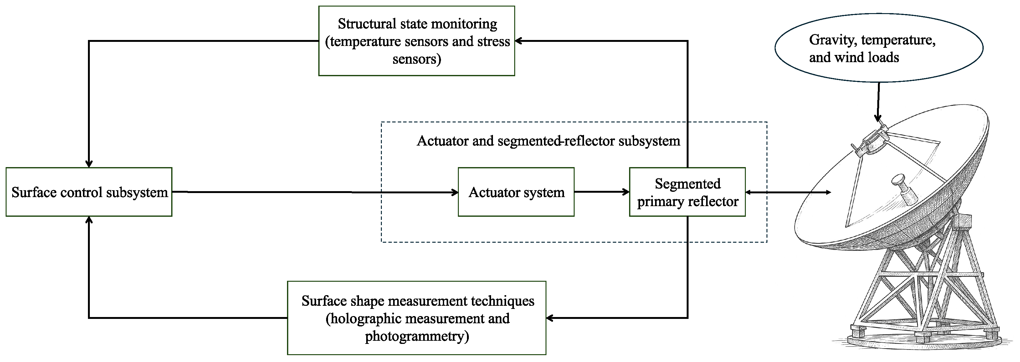
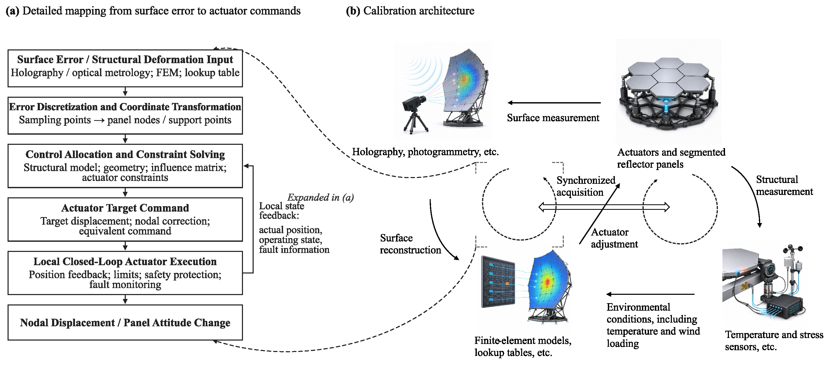
The overall architecture of active surface shape control technology is illustrated in Figure 2. It typically comprises several core functional subsystems, including a primary-reflector measurement subsystem, a reflector surface control subsystem, and a subsystem comprising the actuators and segmented primary reflector. Depending on the structural configuration and operational requirements of a given telescope, auxiliary sensing modules, such as structural state monitoring of the telescope body, may also be incorporated [25,26,27,28]. Gravitational loading, temperature variations, and wind loading can deform the primary reflector. The primary-reflector measurement subsystem determines the resulting surface errors using techniques such as radio holography and photogrammetry, whereas the structural-state monitoring module provides supplementary information, including temperature and structural stress, for model-based deformation estimation. Based on the measured or estimated surface errors, the reflector surface control subsystem calculates the required displacement command for each actuator. Once these commands are transmitted to the actuator controllers, the actuator system changes the positions of the panel support points, thereby adjusting the position and orientation of each reflector panel and restoring the segmented primary reflector to its target surface shape. The corrected reflector can then be measured again, forming a feedback loop for surface correction and long-term surface stability. The following discussion is organized around two stages—system calibration and normal operation—and examines different control and information loops to elucidate the coordination among the primary-reflector measurement subsystem, structural-state monitoring module, reflector surface control subsystem, and actuator and segmented-reflector subsystem.
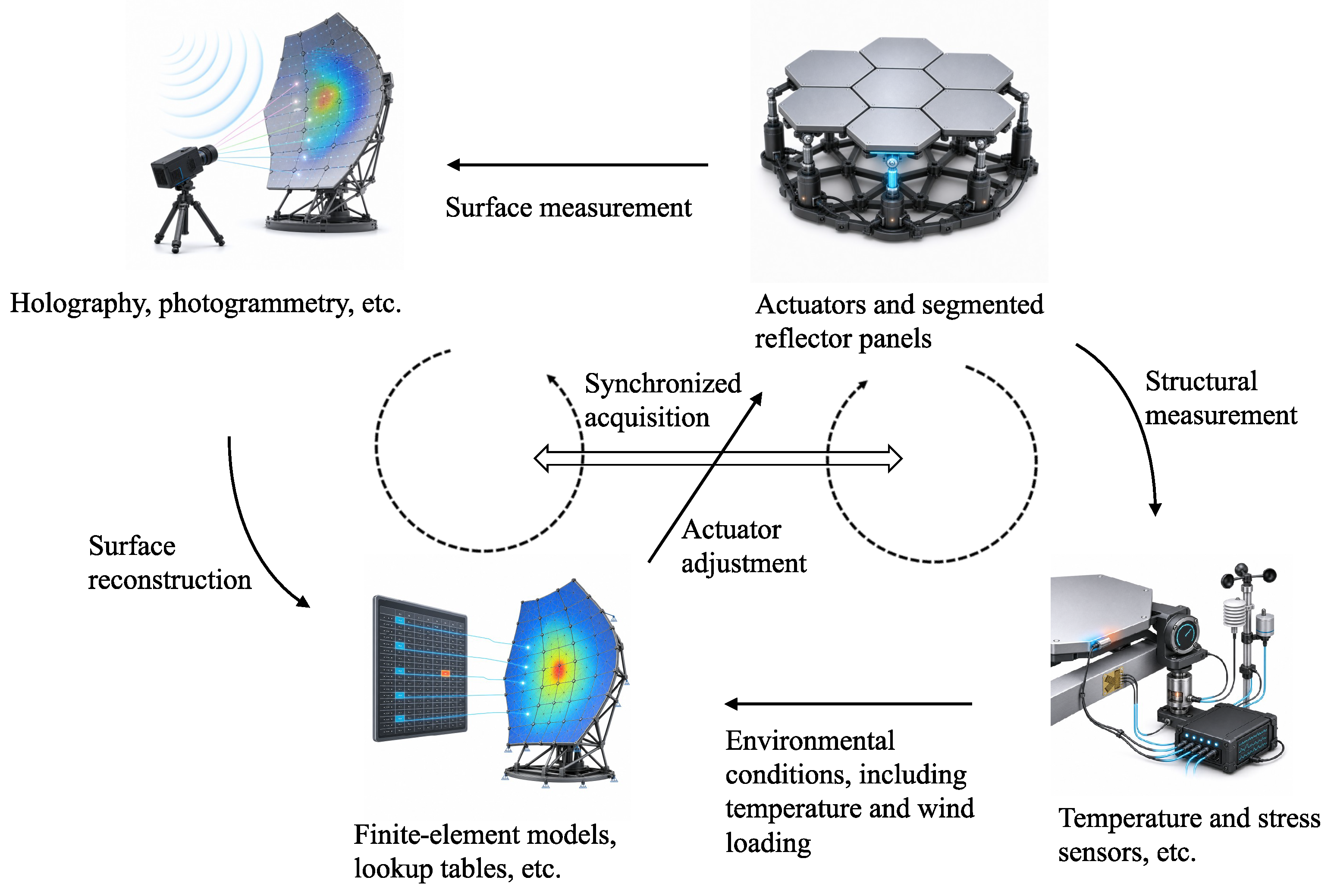
As illustrated in Figure 3, during the system calibration phase, the actual geometric shape or electromagnetic wavefront information of the primary reflector is first measured using techniques such as radio holography and photogrammetry. The corresponding surface errors under different elevation angles and environmental conditions are then obtained through surface reconstruction. Meanwhile, the corresponding elevation angles, temperatures, strains, loads, and external environmental parameters are recorded to establish the relationship between the structural operating states and the actual reflector deformations. The measured surface errors can be used, on the one hand, to update the structural parameters, boundary conditions, and load descriptions of finite element models, thereby improving their accuracy in predicting deformations of the actual telescope structure. On the other hand, they can be directly converted into actuator compensation commands for different elevation angles or representative environmental conditions and stored in the form of lookup tables or parameterized functions. During initial installation and commissioning or subsequent recalibration, multiple iterations of “surface measurement–correction calculation–actuator adjustment–remeasurement” are typically performed until the primary reflector reaches the required accuracy. After model refinement or lookup-table generation, the compensation performance must be further validated under elevation angles and environmental conditions that are not included in the parameter fitting process. The model or compensation dataset is then refined according to the residual surface errors.
This process has been implemented in several large radio telescopes. For example, the reflector segments of the LMT were assembled and pre-aligned off-site, after which a total station, an electronic surveying instrument that determines the three-dimensional coordinates of target points by measuring distances and horizontal and vertical angles, was used for their initial positioning during installation (see Section 3.2). Prior to the first observations, full-aperture holographic measurements were further used to guide adjustments of the four electromechanical actuators located at the corners of each segment, thereby correcting inter-segment piston, tilt, and twist errors and improving the overall alignment of the segmented primary reflector [29].
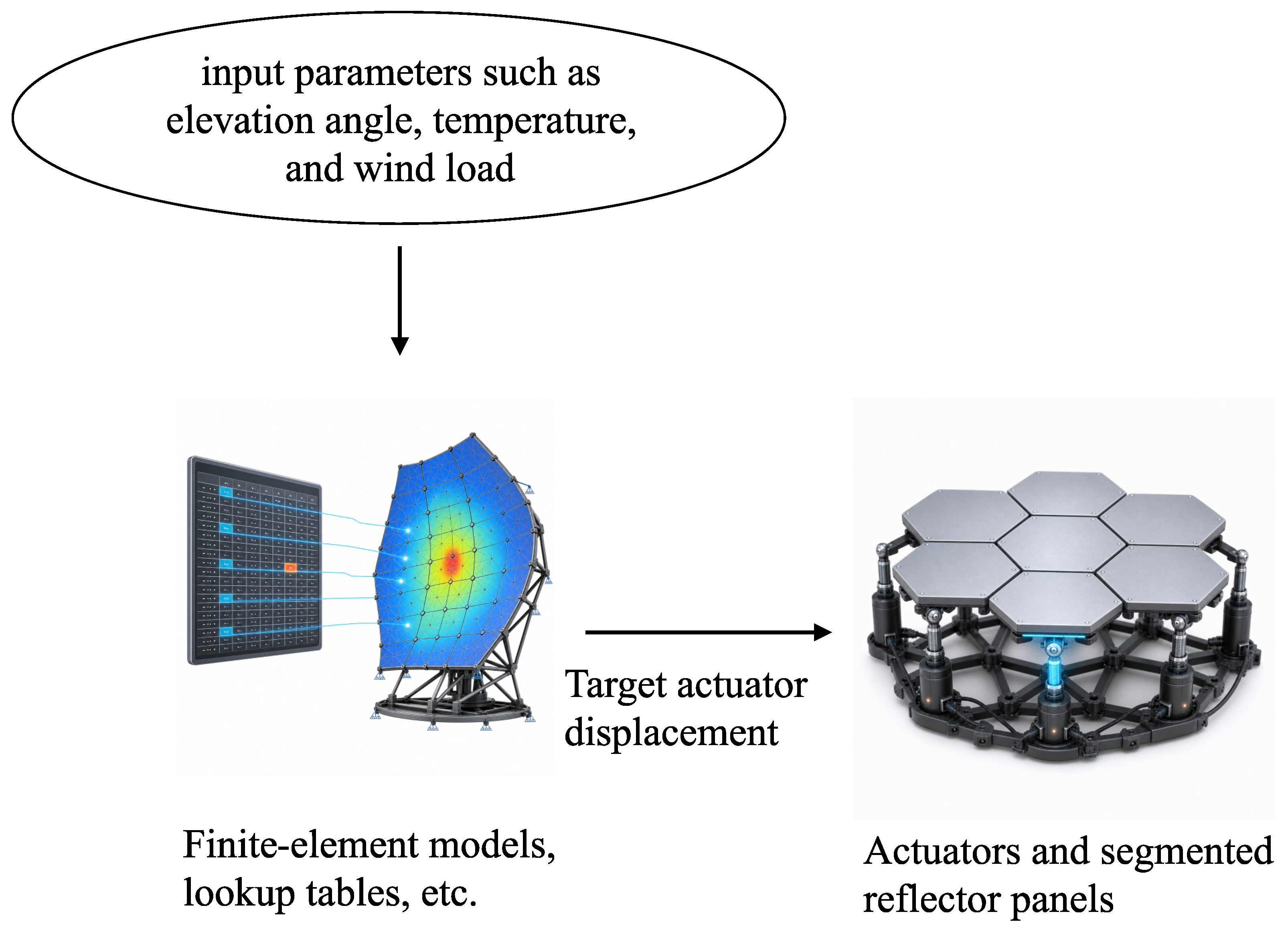
As illustrated in Figure 4, lookup-table-based feedforward compensation is currently one of the most widely used approaches during routine operation. Its information flow can be summarized as “elevation angle → compensation lookup table → actuator commands”. In this approach, the control system retrieves the actuator compensation values obtained during calibration according to the current elevation angle and generates the target position of each actuator through interpolation or parameterized calculation. The Noto 32-m radio telescope employs elevation-dependent polynomial feedforward compensation.The master control computer stores a polynomial model describing reflector deformation as a function of antenna elevation and uses the real-time elevation angle to calculate the target position of each actuator, thereby adjusting the panel support nodes to compensate for gravitational deformation [30]. Lookup-table-based feedforward compensation offers several advantages, including a low online computational burden, rapid command generation, deterministic operation, and straightforward engineering implementation. It is particularly well suited to compensating repeatable elevation-dependent gravitational deformations. However, its compensation capability is constrained by the range of calibration conditions and the density of the sampled data. It is therefore less adaptable to thermal gradients, wind loads, structural-parameter drift, and other non-repetitive disturbances, and residual surface errors may arise when the actual structural state deviates from the calibration conditions.
In addition to directly retrieving compensation values from lookup tables, model-based predictive compensation can also be employed. As illustrated in Figure 4, its information flow can be represented as “elevation angle and structural-state parameters → finite element or reduced-order predictive model → actuator target displacements”. For example, for the Sardinia Radio Telescope (SRT), researchers developed a finite element model incorporating the backup structure of the primary reflector to predict self-weight-induced structural deformations at different elevation angles. Close-range photogrammetric measurements acquired at multiple elevations were subsequently used to infer equivalent inelastic strains, thereby accounting for assembly imperfections, initial self-stress, and thermal effects that were not adequately represented in the original model. Predictions obtained from the updated model can subsequently be used to estimate the target extension of each active-surface actuator and provide a basis for predictive compensation at arbitrary elevation angles by incorporating real-time structural-state information, such as temperature and wind pressure. It should be noted that this method remains at the research stage and has not yet been deployed in the actual active surface operational control of the SRT [31]. The original finite element model may deviate from the measured structural response because thermal strains, assembly errors, and actual joint conditions are not fully represented. The model must therefore be updated using photogrammetric or other measurement data. Compared with fixed lookup tables, model-based prediction can represent structural deformation continuously over the full elevation range and under multiple loading conditions. It can also incorporate temperature, strain, and environmental measurements into deformation estimation, thereby providing greater physical interpretability and a stronger ability to generalize across operating conditions. Its limitations include the complexity of model development, parameter identification, and numerical computation, as well as the sensitivity of prediction accuracy to material properties, boundary conditions, joint stiffness, and sensor placement.
An online global feedback loop comprising “physical primary reflector → surface-shape measurement system or relative-state sensors → surface reconstruction → control-command calculation → actuators” represents a potential direction for compensating time-varying disturbances such as thermal and wind-induced loads. For the 110-m Qitai Radio Telescope (QTT), an active-surface compensation method based on angular feedback between adjacent reflector panels has been proposed, providing a possible implementation pathway for constructing a global surface-shape feedback loop from measurements of the relative states of the panels. However, this method has thus far been evaluated only through mathematical modelling and numerical simulations and has not yet been developed into a mature operational system [32].
Overall, lookup-table-based feedforward compensation offers the highest level of engineering maturity and imposes a relatively low real-time computational burden, whereas finite-element-model-based prediction can extend compensation to a broader range of operating conditions but depends strongly on model accuracy. Existing large radio telescopes therefore continue to rely primarily on lookup tables or calibrated structural models for feedforward compensation, supplemented by periodic surface measurements for model updating and the correction of low-frequency residual errors. Online global surface-shape feedback, by contrast, represents a principal development direction for the next generation of high-precision active-surface systems.

3. Primary Reflector Surface Measurement Methods

The surface measurement subsystem is a critical component of active surface control, providing the primary means of acquiring main-reflector figure-error information. Its measurement results directly affect the reliability of structural model calibration, compensation strategy refinement, and surface accuracy assessment. In large radio telescopes, the primary reflector is subject to complex deformations caused by gravitational loading, thermal gradients, wind disturbances, and long-term operational effects; therefore, accurate identification of these deformation patterns is essential for effective active surface control. In current engineering practice, surface measurement is mainly used for system calibration, maintenance, and model updating. Existing approaches are primarily directed at low-frequency or quasi-static errors, such as gravitational deformation, thermal effects, and structural drift. Their results are commonly used to update finite-element structural models or elevation-dependent surface compensation look-up tables, rather than being directly incorporated into high-bandwidth real-time closed-loop control. Accordingly, improving the temporal responsiveness, spatial coverage, and engineering applicability of surface error measurement remains an important issue for enhancing the performance of active surface control in large radio telescopes. This section reviews the principal methods used for primary-reflector surface measurement in radio telescopes, with emphasis on their basic principles, engineering roles, and functional positioning within active surface control systems.
From an engineering application perspective, surface measurement methods for the primary reflectors of large-aperture radio telescopes mainly include theodolite-based measurement, laser-based measurement, photogrammetry, and radio holography. These methods exhibit significant differences in terms of measurement accuracy, applicable aperture scale, update rate, and engineering implementation complexity, and their suitability must be comprehensively evaluated in conjunction with the specific structural configuration and operational requirements of the telescope.

3.1. Theodolite-Based Measurement Method

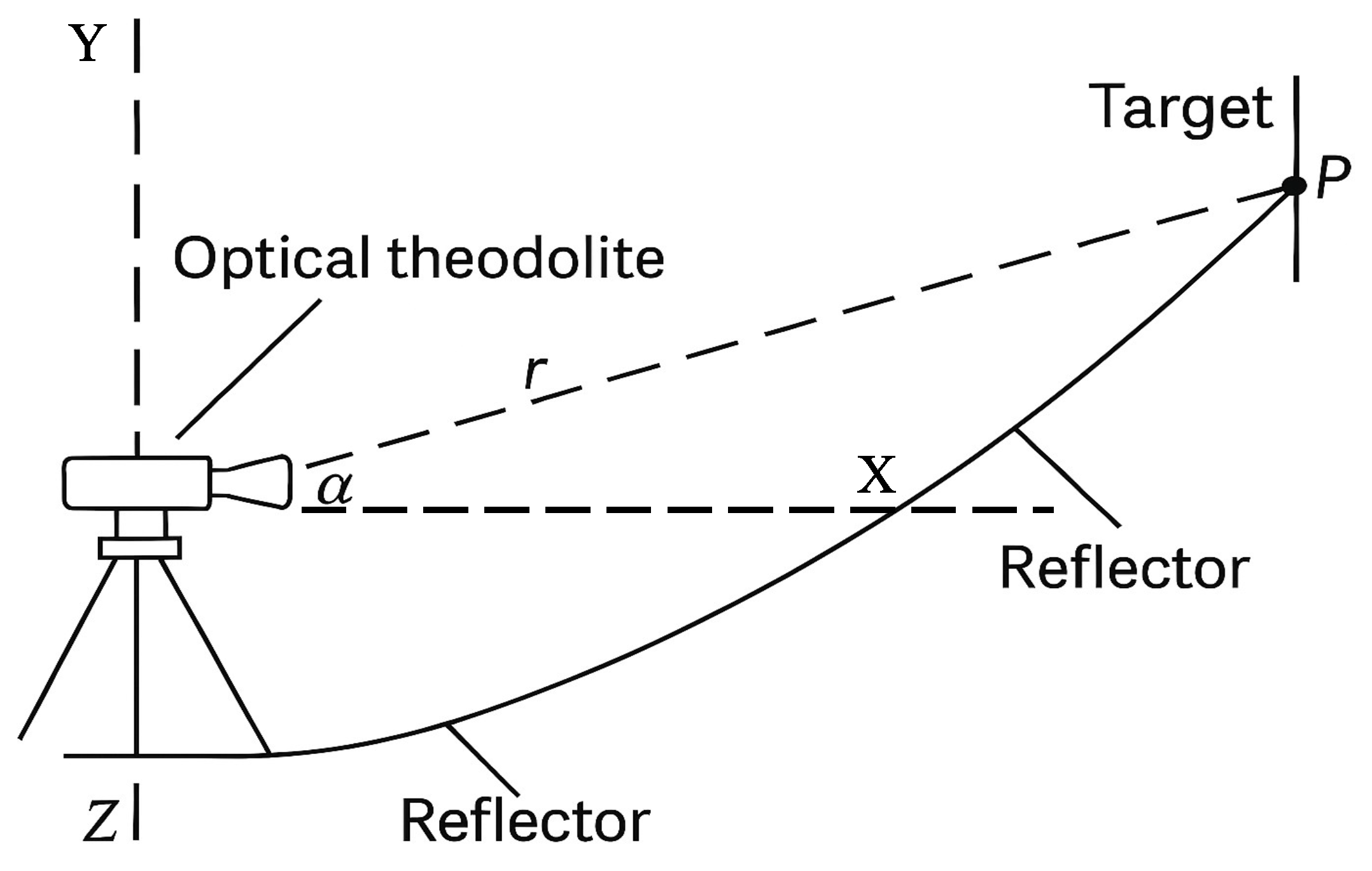
The theodolite-based measurement method is one of the primary reflector surface measurement techniques adopted in early large reflector antennas developed abroad [33,34]. The basic principle of the theodolite-tape measurement method is illustrated in Figure 5. In this method, measurement targets with known positions are placed on the reflector surface, and a theodolite installed near the vertex of the reflector is used to measure the horizontal and vertical angles of each target, thereby determining the deviations between the actual target positions and their corresponding locations on the ideal parabolic surface. This approach features a relatively simple system configuration and strong equipment generality; however, the measurement process relies heavily on manual target placement and visual aiming, making both efficiency and accuracy sensitive to environmental conditions and operator experience. Moreover, the angular resolution of the theodolite and distance measurement errors are amplified under large-aperture and low-elevation conditions, which limits the surface reconstruction capability and makes it difficult to achieve the surface accuracy levels typically required by modern millimeter- and submillimeter-wave radio telescopes (i.e., <100 μ m RMS). Consequently, this method is mainly used in modern engineering projects for initial reflector alignment or as a backup calibration technique.
The Institut de Radioastronomie Millimétrique (IRAM) 30 m millimeter radio telescope employed a modified theodolite-tape method for initial reflector alignment, resulting in an overall reflector surface accuracy of approximately 120 μ m [35]. During the initial construction phase of the Swedish-ESO Submillimeter Telescope, the theodolite-tape method was locally employed during primary reflector surface adjustment to perform preliminary calibration of panel positions, achieving a single-point surface positioning accuracy of approximately 70–80 μ m [36]. The above engineering example indicates that the theodolite-based measurement method exhibited practical utility during the construction of early large radio telescopes; however, its achievable accuracy and level of automation are no longer sufficient to meet the engineering requirements of modern large-aperture active surface systems.

3.2. Laser-Based Measurement Method

Compared with traditional theodolite-based measurements, laser-based measurement methods perform automated acquisition of angular and distance data, significantly reducing the influence of human factors on surface measurement accuracy and greatly improving measurement efficiency. Laser-based measurement methods applied to large radio telescopes mainly include total station measurement, laser tracker-based measurement, and laser scanning measurement.
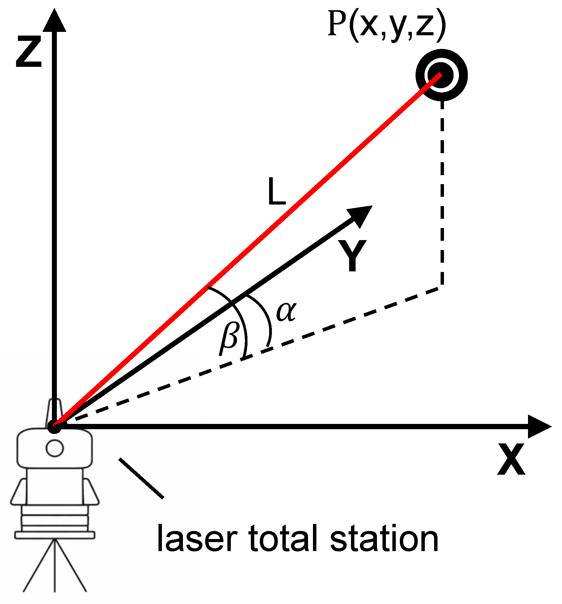
As illustrated in Figure 6, the total station measurement method extends conventional theodolites by incorporating laser ranging capability, enabling automated acquisition of both angular and distance information. It is well suited for large-scale geometric monitoring of telescope structures. The measurement process is typically based on discrete points, with the measurement update rate constrained by the instrument scanning speed. In typical engineering applications, the achievable measurement accuracy is generally at the millimeter level [37]. The primary reflector of FAST is measured using automated total stations to survey reflector nodes. The surface figure error is approximately 2 mm under observing conditions and can be further reduced to the order of 1.5 mm under calibration conditions [38]. The study points out that the measurement system is primarily affected by atmospheric disturbances and suffers from issues such as measurement data latency and inconsistent sampling intervals, which need to be mitigated through improved measurement strategies and the introduction of multi-sensor data fusion approaches. Although the total station measurement method is engineeringly feasible for geometric monitoring of ultra-large-aperture reflectors, its achievable accuracy and update capability remain insufficient to meet the high-precision surface information requirements of active surface shape control for millimeter- and submillimeter-wave observations.
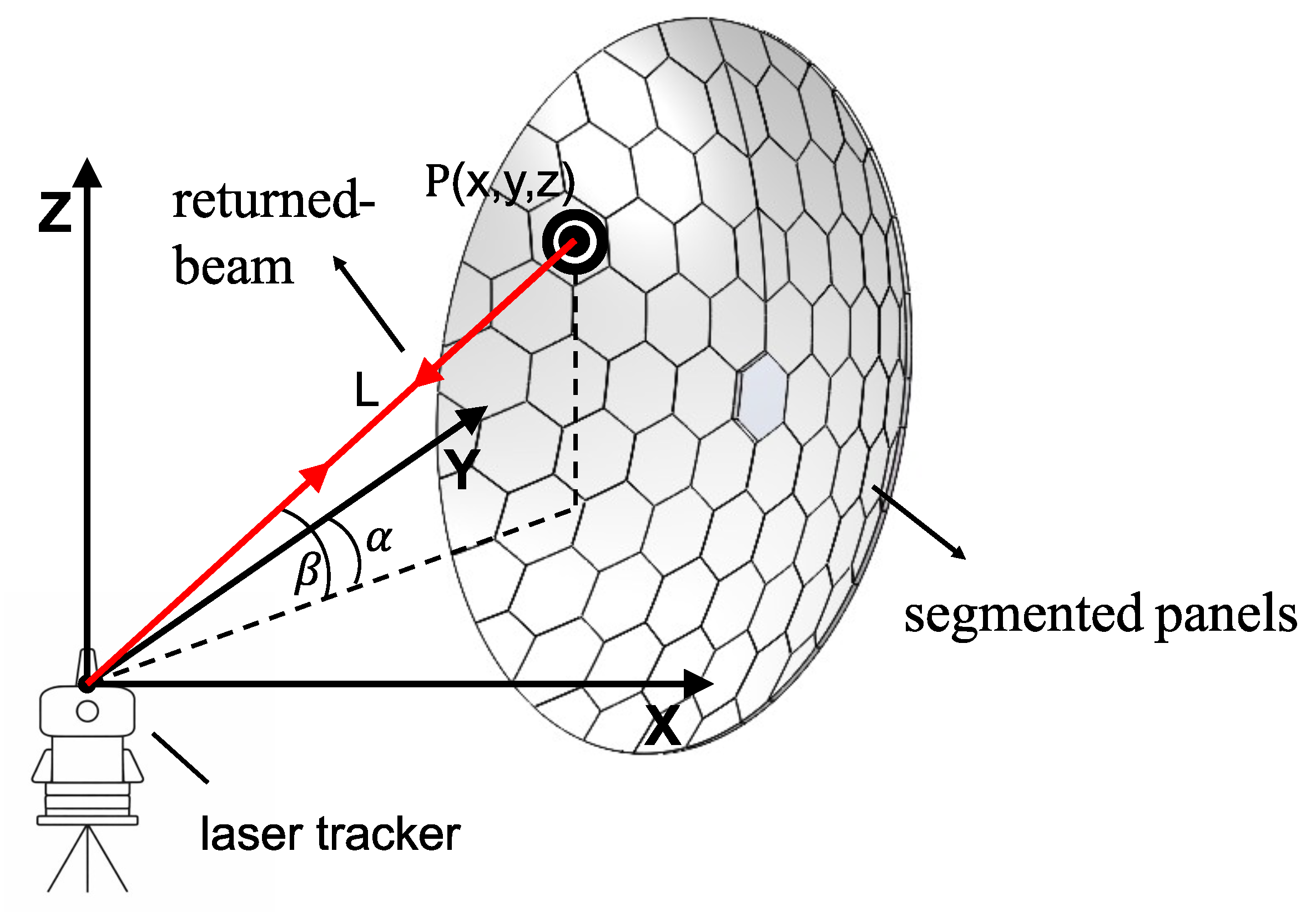
The operating principle of the laser tracker is illustrated in Figure 7. Compared with total stations, this approach incorporates optical feedback and automatic tracking mechanisms, enabling the instrument to automatically align with and continuously track the target. As a result, the influence of manual operations on the measurement process is reduced, leading to further improvements in measurement accuracy and measurement efficiency. However, this method still relies on the deployment of targets, resulting in a limited number of measurable points. Moreover, achieving multi-point measurements in complex outdoor environments remains challenging from an engineering perspective. Consequently, laser tracker-based measurement is mainly applied to optical alignment, structural calibration, and position monitoring of critical components, rather than to large-scale surface measurement and updating in active surface systems. The research team of the Giant Magellan Telescope (GMT) applied a high-precision laser tracker measurement system during the coarse grinding and initial polishing stages of the primary mirror, achieving a laboratory accuracy of up to 2 μ m RMS [39]. The Large Binocular Telescope (LBT) employs laser trackers to measure the positions and orientations of the primary and secondary mirrors, achieving a positioning accuracy of approximately 20 μ m [40].
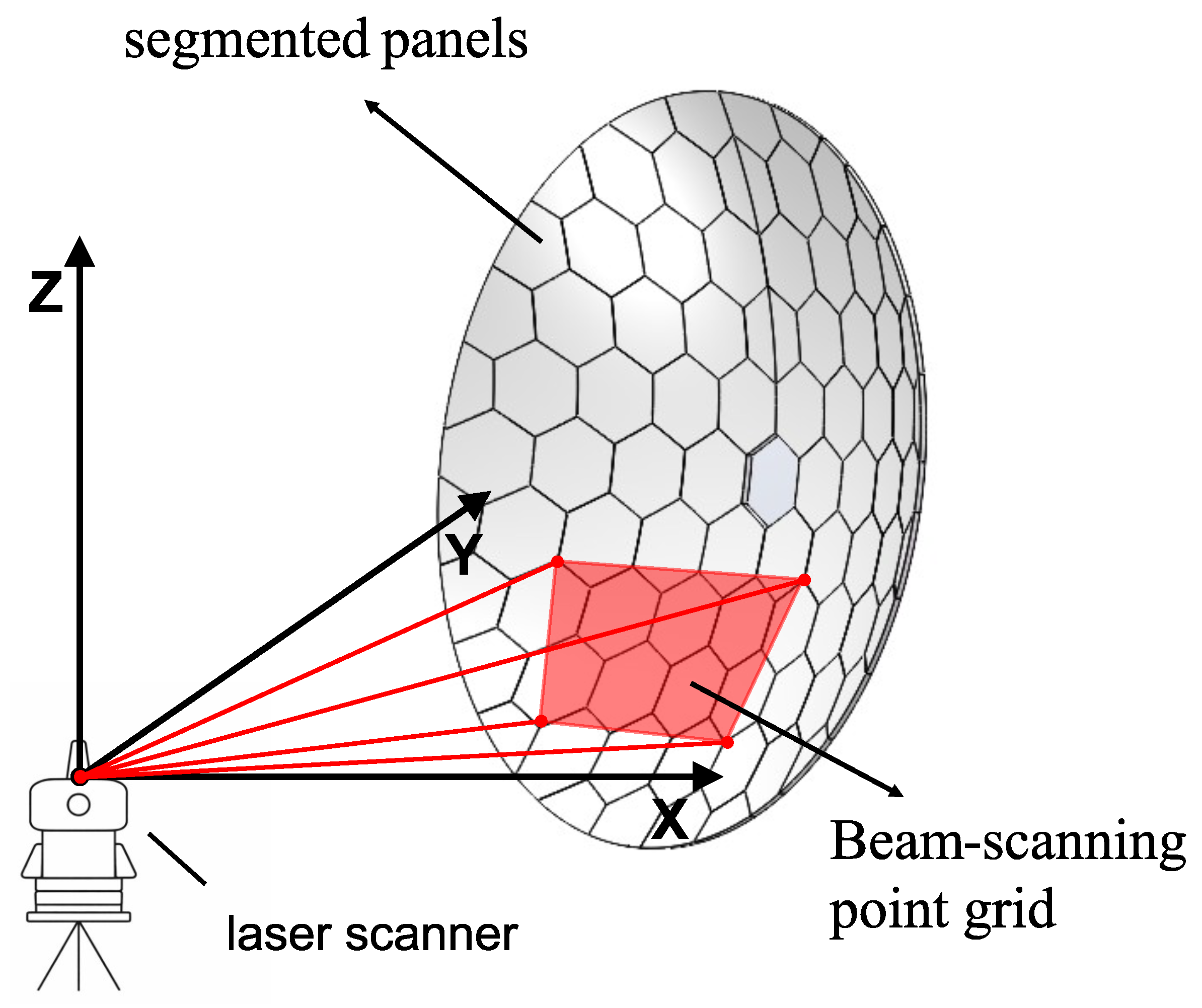
As illustrated in Figure 8, the working principle of laser scanning measurement is based on rapidly scanning the object surface with a laser beam to acquire three-dimensional coordinates, from which the geometric shape of the object is reconstructed.Laser scanning measurement does not require physical targets and is therefore classified as a non-contact measurement technique. At the 20 m radio telescope of the Onsala Space Observatory, a terrestrial laser scanner is used to monitor deformation characteristics of the primary reflector at different elevation angles. The measurement accuracy is 1.5 mm, and the surface fitting residuals are ±1.5 mm [41]. Salas et al. validated a differential measurement strategy based on a terrestrial laser scanner (TLS) at the GBT. In this approach, reference and deformed point clouds acquired at the same elevation angle are registered and differenced to suppress systematic scanner errors that remain relatively stable over short timescales. Point-cloud smoothing and Zernike-mode fitting are then applied to reduce random ranging noise. In the experiment, Salas et al. used the active-surface system to introduce prescribed deformations represented by known Zernike modes. The results showed that the method could detect low-order surface deformations with amplitudes as small as approximately 60 μ m. At wind speeds not exceeding approximately 2 m / s , the discrepancy between the prescribed deformation amplitudes and the TLS measurements remained below approximately 140 μ m. These results demonstrate that differential processing and statistical averaging over multiple points can provide smooth measurements of relative deformation with an effective sensitivity substantially better than the single-point ranging precision of the TLS [26].
Laser scanning offers the advantage of rapidly covering large surface areas; however, the accuracy of a single absolute measurement is readily constrained by factors such as scanning distance, ambient illumination, surface reflectivity, and the intrinsic noise of the instrument. Although differential measurements can substantially improve the detectability of smooth relative deformations, their application to active-surface control at millimetre and submillimetre wavelengths remains contingent on the stability of the reference state, low wind speeds, and controlled environmental conditions.
In addition, early studies of the GBT proposed integrating custom-built laser-ranging instruments mounted on the antenna structure into a unified coordinate-determination system referenced to a stable ground-based ranging network, with the aim of establishing an external absolute coordinate reference for measurements of the reflector surface and other critical structural components. The proposed system comprised 12 ground-based ranging instruments installed on stable monuments around the telescope to establish an Earth-fixed absolute coordinate frame, together with six ranging instruments mounted on the antenna structure. It was designed to measure 2209 reference points on the primary reflector approximately every 8 min. In the proposed approach, distances would be determined from the phase of the returned modulated laser signal and corrected for the group refractive index of air. Range measurements from at least three instruments would then be combined through trilateration to determine the three-dimensional coordinates of each target point. The reflector shape and the positions of critical structural points would subsequently be expressed in the ground-based absolute coordinate frame, providing measurement data for active-surface correction, structural-deformation characterization, and high-precision pointing-model development. The system was expected to achieve a reflector measurement and correction accuracy of approximately 0.1 mm and to provide the structural-metrology basis for attaining a pointing accuracy of approximately 1 arcsec [42]. However, these values represented system design targets rather than the measured performance of the complete system during routine astronomical observations. A subsequent report on the GBT Precision Telescope Control System noted that, although laser ranging was initially regarded as a key enabling technology for high-frequency operation, the system was still far from being ready for routine astronomical use at the end of the first commissioning phase in autumn 2002. The GBT subsequently moved away from treating laser ranging as the near-exclusive core technology for its short-term development and instead adopted a combined strategy incorporating structural temperature sensing, tilt and other targeted metrology, structural modelling, and measurements derived from astronomical observations [43].

3.3. Photogrammetric Measurement Method

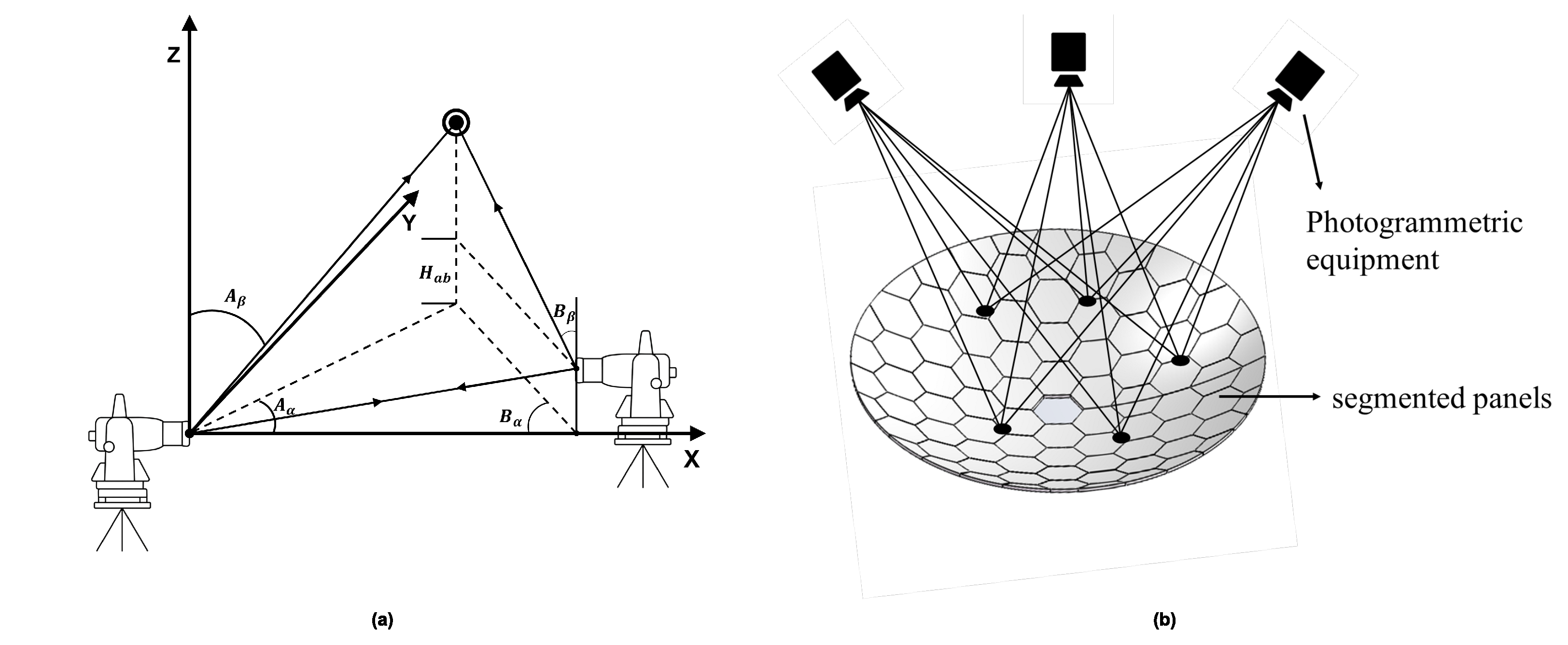
As illustrated in Figure 9, photogrammetry acquires multiple images of the same target from different viewing angles using imaging devices, and reconstructs the three-dimensional coordinates of object feature points by establishing correspondences across images based on the principle of triangulation. This method offers advantages such as non-contact measurement, high efficiency, and flexible deployment; however, it is relatively sensitive to observing environment conditions. Photogrammetry typically requires sufficient and stable illumination conditions to ensure image quality. Strong illumination variations, shadows, and the highly reflective properties of reflector surfaces can all introduce measurement errors [44].
In engineering practice, photogrammetry has been applied to reflector surface measurements in multiple radio telescopes. During the construction and commissioning phases, the SRT employed close-range photogrammetry to perform multiple high-precision measurements of the primary reflector, achieving a measurement accuracy in the range of 0.024–0.1 mm [45]. The 13.2 m radio telescope of the VLBI Global Observing System (VGOS) at the Hartebeesthoek Radio Astronomy Observatory in South Africa also employs photogrammetry for primary reflector surface measurement, achieving a surface figure accuracy of approximately 0.087 mm RMS [46].
For ultra-large-scale radio telescopes, the implementation mode and achievable accuracy of photogrammetry exhibit significant differences. Taking FAST with a 500 m aperture as an example, a local region of the primary reflector is adjusted into a spherical cap with a radius of approximately 300 m, and photogrammetry is applied to reconstruct the three-dimensional coordinates of the nodes in this region. Under the target spherical surface condition with a radius of 300 m, the reconstructed node positions exhibit an average fitting residual of approximately 12.299 mm relative to the ideal spherical surface [47].
Based on existing engineering applications, photogrammetry can achieve a measurement accuracy on the order of approximately 0.02–0.1 mm for small- and medium-aperture radio telescopes, making it suitable for initial surface measurement and geometric reconstruction of primary reflectors. However, for ultra-large-aperture radio telescopes, factors such as significantly increased observation distances and insufficient surface texture lead to error amplification with viewing distance, making it difficult for photogrammetry to meet the submillimeter-level surface accuracy requirements of active surface control.

3.4. Holographic Measurement Method

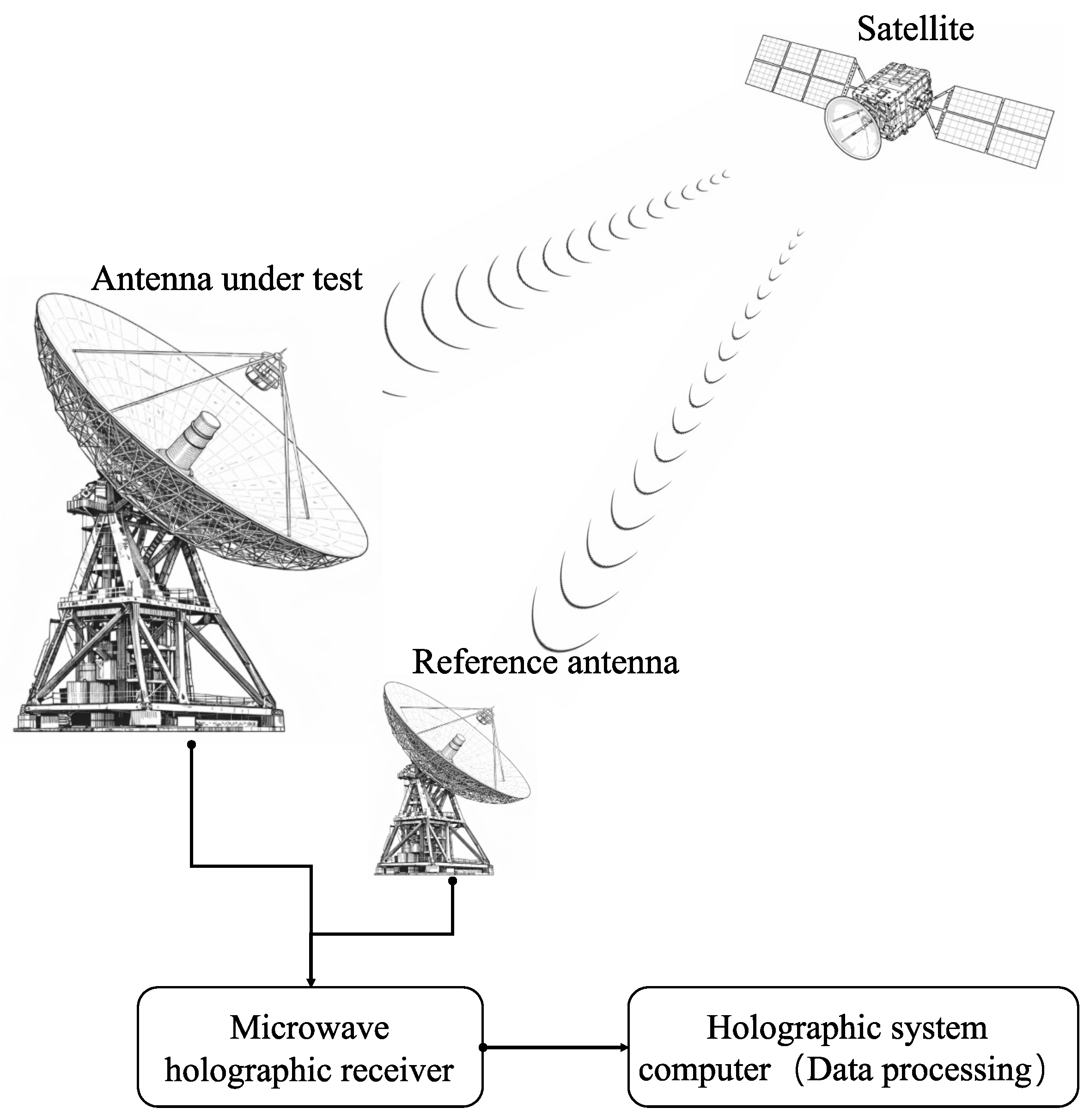
As illustrated in Figure 10, holographic measurement is based on the Fourier transform relationship between the far-field radiation pattern and the antenna aperture field. By measuring the amplitude and phase of the radiated beam in the spatial direction-cosine coordinate system and applying inverse Fourier transformation, the complex aperture field distribution can be reconstructed, from which the surface figure errors of the primary reflector are derived. It should be noted that when holographic measurements are performed through the complete optical path comprising both the primary and secondary reflectors, the reconstructed aperture-phase error represents the combined wavefront error of the antenna optical system and cannot be interpreted simply as the independent geometric surface error of the primary reflector. When active-surface corrections are derived from such measurements, the corrective displacements are applied to the primary reflector, but they may compensate for the combined effects of errors in both the primary and secondary reflectors on the system wavefront. Previous studies have shown that low-order manufacturing errors in the secondary reflector can be compensated by introducing an equivalent counteracting wavefront correction through the active primary reflector, thereby improving the overall antenna performance [48]. This method features non-contact measurement, full-aperture coverage, high sensitivity, and strong system integrability. Depending on whether phase information from a reference signal is acquired, holographic measurement can be classified into phase-referenced methods and phase-retrieval methods. According to the spatial distance between the measurement points and the antenna, it can also be categorized into near-field and far-field holography.
Holographic measurement was proposed in the 1960s and, following extensive experimental validation and engineering refinement during the 1970s and 1980s, was subsequently deployed in large radio telescopes such as the Effelsberg 100 m Radio Telescope and the IRAM 30 m Telescope for reflector surface adjustment and performance evaluation [21,49]. Since the 2000s, driven by increasingly stringent surface accuracy requirements for millimeter- and submillimeter-wave observations, holographic measurement has rapidly advanced toward higher precision and operation at higher frequency bands. Near-field holography was applied to the prototype antenna of the Atacama Large Millimeter/submillimeter Array (ALMA) for reflector surface adjustment, achieving a measurement accuracy of approximately 10 μ m and reducing the antenna surface error to below 20 μ m RMS [50]. During this period, holographic measurement was further adopted in radio engineering applications. For example, the 10.4 m radio telescope at the Raman Research Institute (RRI) employed radio holography at 12 GHz to measure the antenna surface, yielding a surface RMS error of approximately 350 μ m and a measurement accuracy of about 50 μ m [51]. In addition, during subsequent upgrades, the GBT introduced a 12 GHz radio holography system. Through multiple rounds of holographic measurements and actuator calibration updates, the RMS surface error of the primary reflector was reduced from approximately 390 μ m to about 240 μ m [18].
In recent years, research on holographic measurement has progressed beyond basic surface reconstruction towards faster data acquisition, the suppression of systematic errors, and online implementation. One class of methods exploits prior information, such as the reflector dimensions, panel layout, and characteristic error modes, to represent panel translations, tilts, twists, and low-order system aberrations using a set of basis functions. Their coefficients are then estimated directly by solving a low-dimensional inverse problem, thereby reducing the number of required beam-pattern samples. Measurements obtained with the Yebes telescope showed that the linearized holography method could achieve results comparable to those of the conventional method using only approximately 20 % of the sampling points, theoretically reducing the measurement time from 4 h 12 min to approximately 50 min [52]. Another class of methods suppresses multipath interference using simultaneous multifrequency near-field holography. A frequency-comb beacon, a broadband dual-channel receiver, and a real-time fast Fourier transform (FFT) correlator are used to acquire complex beam patterns at multiple frequencies within a single scan. Frequency-domain averaging is then applied to reduce systematic phase errors caused by reflections from the ground, support struts, and structures near the feed [53].
In addition, out-of-focus holography recovers low-order aperture aberrations by jointly fitting one in-focus power beam map and two power beam maps acquired at known defocus offsets, without requiring a separate phase-reference antenna. Studies conducted with the Effelsberg 100-m telescope further established standardized observing and data-processing procedures and explored the use of measured residual gravitational deformations to refine the lookup table for the active subreflector. In engineering applications, out-of-focus holographic measurements first require the selection of a bright point source with a signal-to-noise ratio of approximately 200 or higher. The observing wavelength and axial defocus of the subreflector are then determined according to the receiver frequency, telescope sensitivity, and desired spatial resolution. Before each measurement set, cross-scans are performed to correct the antenna pointing and determine the optimal focus. Continuous scanning is then used to acquire one in-focus beam map and two out-of-focus beam maps with known positive and negative axial offsets. At the Effelsberg telescope, acquisition of a complete three-map set requires approximately 45 min. Following outlier removal, gridding, baseline subtraction, noise-diode calibration, atmospheric-opacity correction, and flux calibration, data acquired along different scanning directions can be combined using the basket-weaving method to improve the signal-to-noise ratio. The three beam maps are then jointly fitted by nonlinear least squares using the pyoof software, which incorporates the telescope blockage pattern, feed-illumination function, and defocus-induced optical-path-difference model. This procedure yields the Zernike coefficients describing low-order, large-scale aberrations and the corresponding aperture-phase-error map. After the orientation and sign convention relating the phase map to the actuator coordinate system have been verified through active-surface on–off comparisons or by deliberately applying known actuator offsets, measurements obtained at multiple elevation angles are fitted to derive a gravitational-deformation model. The residual phase errors are subsequently converted into actuator displacements and used to refine the original finite-element-model-based lookup table. The effectiveness of the correction is finally evaluated through gain measurements of calibration sources. The accuracy and repeatability of this method depend primarily on the signal-to-noise ratio of the target source, observing frequency, magnitude of defocus, map coverage, scan-sampling density, pointing and focus drifts among the three beam maps, atmospheric opacity, and the increased air mass at low elevations. Additional limitations arise from the accuracy of the telescope geometry and blockage model and of the feed-illumination function, as well as from edge taper across the aperture, the selected Zernike order, correlations among fitted parameters, and variations in thermal gradients and wind loading during the observations. In particular, the aperture edge is generally less well constrained because of its weaker illumination. Excessive defocus reduces the signal-to-noise ratio of the out-of-focus beams and increases the required scanning time, whereas insufficient defocus fails to provide adequate constraints for phase reconstruction [54].
Overall, owing to its high precision, full-aperture coverage, and its ability to characterize surface errors directly related to the observing frequency band, holographic measurement has become one of the core techniques for reflector surface accuracy calibration in large radio telescopes. Compared with geometric measurement approaches such as laser-based methods, holography offers advantages in the stability and engineering efficiency of full-aperture surface information acquisition; however, it still relies on stable observing conditions, and its data acquisition and processing typically require non-negligible time, making it difficult to be directly applied to real-time closed-loop control. In engineering practice, holographic measurement is therefore commonly employed as a tool for periodic calibration and model updating, in coordination with structural models, gravity and thermal compensation models, and local real-time sensing techniques.
In addition, millimetre-wave wavefront sensing can be used to measure, in real time, time-varying optical-path errors caused by deformation of the telescope optical structure. Tamura et al. [55] proposed a method based on aperture-plane interferometry, in which the same broadband reference signal is sequentially fed to radiators positioned at different locations across the primary reflector. Correlation measurements are used to determine changes in the excess optical-path length from each sampled position to the focal point, thereby characterizing dynamic wavefront variations relative to a holographically calibrated reference state. This method provides micrometre-level measurement capability and high temporal resolution, making it suitable for detecting large-scale, low-order deformations induced by wind and thermal loading. However, it relies on stable transmission of the reference signal and is susceptible to long-timescale systematic errors, such as thermally induced drift in the optical fibres. For the 16–24 GHz prototype, the standard deviation of the measurement error obtained in laboratory tests was 17.4 μ m. Nakano et al. [56] subsequently conducted an on-telescope validation of this method using two reference-signal radiators installed on the primary reflector of the Nobeyama 45-m telescope at radial distances of 5 m and 16 m from its centre. The system measured the differential excess optical-path length from the two sampled positions to the focal point at an update rate of 10 Hz. Under strong-wind conditions, the fluctuations in differential optical-path length increased markedly. After 1–5 Hz band-pass filtering, the observed vibration behaviour corresponded to the relative displacement inferred from accelerometers mounted on the primary-reflector backup structure, and the vibration components in the power spectrum were consistent with the known frequencies of wind-induced structural oscillations. The statistical uncertainty in the differential optical-path measurement, estimated from the white-noise component, was 7.71 μ m RMS. These results demonstrated on a full-scale telescope that the two-point prototype could monitor wind-induced dynamic optical-path variations at a 10 Hz update rate and with micrometre-level statistical sensitivity. However, full-aperture wavefront reconstruction has not yet been achieved.
Table 1 presents a systematic summary of the technical characteristics of commonly used surface measurement methods. The measurement times listed are representative values reported in the literature and may vary depending on the reflector diameter, required accuracy, sampling density, measurement strategy, and environmental conditions. Overall, laser scanning, photogrammetry, and radio holography constitute the main development directions of global surface measurement technologies for large radio antennas, each corresponding to different levels of measurement accuracy, application scenarios, and engineering implementation conditions.
Among these methods, laser scanning measurement involves relatively high equipment costs, and its achievable accuracy is strongly affected by working distance and environmental conditions. It is therefore more suitable for small-area measurements, local deformation detection, and rapid condition assessment. Photogrammetry generally provides lower overall accuracy, with typical measurement distances on the order of several hundred meters or less. However, owing to its high measurement efficiency and flexible system deployment, it is well suited for rapid large-area reflector measurements and geometric reconstruction. Radio holography offers high measurement accuracy and enables high-fidelity reconstruction of the global shape of the primary reflector. From an engineering perspective, it is not directly constrained by antenna aperture size; however, the measurement process typically depends on specific observing conditions and requires the antenna to operate under controlled pointing or attitude states.

4. Surface Control Strategies

4.1. Mapping Surface Errors to Actuator Control Variables

A key step in surface control strategies is to translate global surface errors, or structural deformations predicted by a model, into target control variables that can be executed by individual actuators. Surface measurement typically provides geometric deviations over a continuous reflector surface or at discrete sampling points, whereas the actuators act only on a finite number of panel support nodes or panel corner points. Therefore, there is no simple one-to-one correspondence between the measured surface errors and the actuator commands. After surface errors are reconstructed using radio holography, optical measurement, or related techniques, or after structural deformations and compensation requirements are predicted by finite-element models or elevation-dependent look-up tables, a mapping relationship must be established between the global surface deviations and actuator adjustments. This mapping should account for the reflector structural model, the panel support topology, and the actuator layout [18,64].
In practical engineering implementations, this mapping is typically established based on finite-element structural models, panel geometric adjustment relationships, and actuator or panel-adjustment influence matrices. After calibration or system commissioning, the resulting mapping can be consolidated into elevation- or operational-condition-dependent pre-calibrated look-up tables, enabling rapid generation of actuator target adjustments. For segmented-panel primary reflectors, the control system generally first discretizes global surface errors onto panel nodes, support points, or key sampling points, and then computes the required displacement corrections at each support point according to the panel geometry, support topology, and actuator layout. Wang et al. investigated actuator distribution and panel segmentation in radio telescopes, demonstrating that the number and layout of actuators, as well as the form of the panel units, can significantly influence the effectiveness of surface error compensation and the redundancy of the control system [65]. Sun et al. investigated the Tianma 65-m radio telescope and calculated actuator adjustments based on primary-reflector surface errors obtained from microwave holography measurements. Their study indicated that converting surface errors into actuator control variables requires consideration of panel geometric relationships, support-node locations, and the active surface adjustment model [66]. Therefore, the control allocation process is not merely an error-inversion problem, but a geometrically and structurally constrained optimization problem.
When solving for actuator target commands, various engineering constraints must also be considered, including actuator stroke, speed, load capacity, resolution, dead zones, failed actuators, and the coordinated motion of adjacent panels. Ideally, control allocation should minimize the overall RMS surface error while avoiding local overcorrection, actuator saturation, and discontinuous deformation between neighbouring panels. For active surface systems dominated by low-frequency or quasi-static compensation, the higher-level surface control system typically generates actuator target displacements or equivalent control commands. The local actuator control system then tracks these commands under position feedback, safety limits, and fault-protection constraints, while feeding back actual positions, operating states, and fault information to the higher-level system. In this way, the surface control layer and the local execution layer form a hierarchical architecture, as shown in Figure 11, consisting of global error estimation, control allocation, target-command generation, and local closed-loop execution [64,67,68].
Therefore, the performance of a surface control strategy depends not only on the accuracy with which surface errors are measured or predicted, but also on the fidelity of the mapping model that converts these errors into actuator commands, the extent to which control allocation satisfies structural and actuation constraints, and the ability of local actuators to reliably track higher-level commands. Without this control allocation process, even high-precision surface error information cannot be effectively translated into practical reflector correction capability.

4.2. Typical Engineering Implementations and Technical Features

To generate and update actuator control variables from global surface deviations, different radio telescopes have developed distinct implementations of active surface control according to their structural configurations, observing frequency bands, surface accuracy requirements, and available measurement techniques. Existing engineering practices are generally organized around model-based prediction, look-up-table compensation, periodic surface measurement, structural state monitoring, and low-frequency updates of control commands. These implementations therefore involve trade-offs among surface accuracy maintenance, update frequency, and engineering complexity [23,24,25,31].
In earlier engineering practices, control of the primary reflector in radio telescopes often relied on model-driven or measurement-calibrated look-up-table compensation. During initial commissioning, finite element analysis or holographic/optical measurements are used to determine the deformation of the primary reflector at different elevation angles. The resulting error distributions are stored to construct a “telescope attitude → actuator adjustments” lookup table. During routine observations, the control system retrieves the corresponding control commands from the lookup table according to the current telescope attitude and transmits them to all actuators. In addition to this established engineering approach, which uses elevation angle as the input and primarily compensates for gravitational deformation, several studies have explored incorporating environmental state variables, such as structural temperature, into lookup tables to predict and compensate for thermally induced deformation. During the construction phase of the SRT, an open-loop predictive compensation scheme based on structural temperature measurements was proposed. In this scheme, a finite element model would first be used to predict antenna deformations under different structural temperature states, thereby establishing a lookup table relating the temperature state to the corresponding structural deformation. During operation, measurements from temperature sensors distributed across the antenna structure would serve as inputs to the lookup table. The deformation predicted for the current temperature state would then be retrieved and used to determine the target position of each active-surface actuator, thereby compensating for structural deformation induced by thermal loading [69]. After the SRT became operational, the lookup table implemented in practice was constructed from photogrammetric measurements acquired at different elevation angles. During operation, the control system retrieves the corresponding translational and rotational corrections according to the current elevation angle to compensate for gravitational deformation. As of the subsequent scientific commissioning phase, compensation for thermally induced and wind-pressure-induced deformations remained dependent on the further development of advanced metrology techniques [25]. At the Effelsberg telescope, the active surface is implemented on the 6.5-m-diameter subreflector rather than on the 100-m primary reflector. The subreflector is equipped with 96 actuators that modify its surface shape to compensate for large-scale aberrations of the primary reflector. Finite element analysis of the antenna mechanical structure was used to calculate gravitational deformations at 11 discrete elevation angles. The corresponding displacements of the 96 subreflector actuators were then derived and stored in a lookup table. During observations, the control system interpolates between the lookup-table entries for the two adjacent elevation angles according to the current antenna elevation, thereby calculating the required active-subreflector shape [54]. In the case of the 100-m GBT, finite-element models were initially used to establish the primary-reflector deformations at different elevation angles as global control inputs, generating 2209 actuator target-position vectors. Once in operation, these models were incrementally corrected using radio-holographic observations to improve the control accuracy [22]. For the 10-m Caltech Submillimeter Observatory (CSO) telescope, radio holography was used to measure surface errors at different elevation angles. These errors were then converted into the required corrections at individual support points and stored in elevation-dependent tables [70]. These methods are structurally straightforward and operationally reliable, making them well-suited for compensating low-frequency or quasi-static gravitational deformations. However, their performance is highly dependent on the initial model and calibration accuracy, and they have limited capability to adapt to non-uniform thermal deformations, wind-induced disturbances, or long-term structural drift.
As telescope apertures increase and observing frequencies extend to shorter wavelengths, higher surface accuracy is required under gravity-, thermal-, and wind-induced structural variations. To further improve the precision and robustness of conventional model- or look-up-table-based compensation, various sensor-enhanced global control schemes have been introduced. In the 50-m LMT, gravitational deformation of the primary reflector is calculated from finite-element models as a function of elevation, whereas structural deformations induced by thermal gradients and quasi-static wind loading are characterized using temperature sensors and strain gauges deployed at critical locations. The sensor data are incorporated as inputs to the finite-element model to estimate primary-reflector deformations under different operating conditions, from which actuator target displacements are further derived for compensation. This strategy mainly addresses low-frequency and quasi-static deformation components and performs global surface adjustment through a model-driven open-loop control approach [71]. The FAST adopts a measurement-driven global surface adjustment strategy. Multiple total stations are deployed to measure approximately 700 reflector nodes within the illuminated aperture during observations at minute-level intervals. The measured nodal deviations are then used to calculate actuator adjustments, which are issued to 2226 actuators for surface compensation [38]. Compared with purely look-up-table-based compensation, the sensor-enhanced strategy adopted by the LMT improves the ability to capture environmental disturbances and structural state variations, while still relying primarily on model-based estimation. FAST, by contrast, is closer to a measurement-driven low-frequency global adjustment scheme, in which actuator corrections can be directly derived from measured nodal geometric deviations. However, its measurement frequency and accuracy are constrained by the total-station system and field conditions, and therefore should not be regarded as equivalent to high-bandwidth real-time closed-loop control.
In existing dual-reflector telescopes, the active primary reflector and the subreflector generally provide operationally distinct but functionally complementary corrections for different types of optical error. The active-surface system is primarily used to correct panel installation errors and residual non-homologous surface deformations of the primary reflector relative to the target surface or best-fitting reflector. By contrast, axial and lateral translations of the subreflector, together with tilt adjustments where necessary, compensate for changes in the overall focal length and optical axis of the primary reflector and for primary–subreflector misalignment caused by deformation of the subreflector support structure.
During construction of the GBT, photogrammetry was used to determine the positions of reflective targets installed at panel corners near the actuators. These measurements were then used to derive zero-point corrections for the individual active-surface actuators, enabling the primary reflector to attain its design shape near the reference setting elevation of 50.3 ° . As the elevation changes, the primary reflector remains approximately paraboloidal under gravitational loading, but its focal length varies. At the same time, the offset feed arm supporting the subreflector and the Gregorian receiver cabin undergoes gravitational deflection. The GBT compensates for these global changes through subreflector focus tracking. Specifically, the lateral and radial displacements of the subreflector are retrieved as functions of antenna elevation to restore focus and improve the gain at the Gregorian focus. For non-homologous deformation of the primary reflector, a finite element model predicts the elevation-dependent displacement of the primary-reflector backup structure relative to the reference setting elevation. The predicted deformation is decomposed into a best-fitting paraboloid and the residual surface error relative to that paraboloid. The residual component is then converted into primary-reflector actuator adjustments and applied through an elevation-dependent lookup table. Functionally, subreflector focus tracking primarily compensates for focal mismatch caused by changes in the overall focal length of the primary reflector and by feed-arm deflection, whereas the active primary reflector mainly corrects residual non-homologous deformation relative to the best-fitting paraboloid. The out-of-focus holographic measurements were performed while the existing finite-element-model-based active-surface correction was operating normally. The resulting measurements therefore represented the large-scale residual wavefront errors remaining across the complete telescope optical system after application of the existing corrections. Residual wavefront errors measured at different elevations were subsequently fitted with elevation-dependent models of the Zernike coefficients, which were incorporated as empirical corrections into the original finite-element active-surface model [62].
With next-generation 50-m-class large submillimetre telescopes such as AtLAST targeting surface accuracies at the ≤20 μ m RMS level, compensation methods relying primarily on finite-element look-up tables, periodic holographic calibration, and limited temperature or strain sensing face increasing challenges in maintaining long-term surface stability under large-aperture conditions and complex environmental disturbances. AtLAST concept studies indicate that future systems will require reliable full-aperture metrology and active surface control architectures capable of operating under such conditions. Potential technical routes currently under discussion include direct surface measurement based on laser scanning, millimetre-wave wavefront sensing, and laser-interferometric methods for tracking optical path variations [11].
In addition, the effect of anomalous refraction relative to the beamwidth may become particularly important for electrically large single-dish telescopes with D / λ > 10 4 . Anomalous refraction arises along the atmospheric propagation path traversed by the incident electromagnetic waves and therefore cannot be measured directly by conventional metrology systems, such as encoders and inclinometers, which sense only the mechanical attitude or structural displacement of the telescope. Anomalous refraction causes an apparent displacement of the astronomical source relative to the beam centre, thereby biasing the corrections derived from pointing calibration. During long integrations, this time-varying displacement can also broaden the effective beam and reduce the observational gain. Because these variations occur on timescales of several seconds and are highly stochastic, they cannot be removed through conventional static calibration and instead require independent, synchronous measurements during astronomical observations. In this context, radiometer-based millimetre-wave wavefront sensing, which samples atmospheric emission along the astronomical line of sight across different regions of the aperture and uses these measurements to estimate the differential electrical-path length and wavefront tilt, offers a potential means of synchronously monitoring anomalous refraction and implementing real-time tip–tilt compensation [72,73].
The temporal characteristics of different disturbances provide a key basis for determining the sampling rate of the measurement network and selecting an appropriate compensation strategy. In large radio telescopes, gravity, wind loading, and non-uniform thermal fields can deform the primary reflector, feed-support structure, and telescope axis system through attitude-dependent, transient, or slowly varying processes. Although anomalous refraction (AR) does not directly cause structural deformation, it can induce wavefront tilt and apparent pointing drift over relatively short timescales. Because these disturbances differ substantially in their underlying mechanisms, repeatability, and rates of evolution, Table 2 summarizes the principal factors affecting telescope surface, pointing, and wavefront accuracy, together with their characteristic timescales, to guide the selection of measurement and correction schemes.
In recent years, machine learning has begun to show potential in surface control systems, particularly for rapid deformation prediction, surrogate finite-element modeling, and measurement-data analysis. Zhang et al. proposed a graph neural network (GNN)-based surrogate model for real-time prediction of primary-reflector deformations in large-aperture active-surface radio telescopes using elevation angle information and sparse temperature sensor data. The predicted deformations show good agreement with high-fidelity finite-element analyses, with an RMS error of approximately 0.2 mm, demonstrating the feasibility of machine-learning-based approaches for rapid estimation of active surface deformations [74].
Cheng et al. proposed a random-forest-regression-based deformation prediction model for a primary reflector surface (PRS) single panel, enabling real-time prediction of the full three-dimensional deformation field of the panel under disturbances induced by six actuators. The predicted RMS deformation differs from photogrammetric measurements by less than 20 μ m, suggesting a potential data-driven approach for relating local actuator-induced responses to global panel deformation behavior [75]. Overall, machine learning methods show promise for rapid surface error prediction, surrogate finite-element modeling, and measurement-data analysis. However, most existing studies remain at the simulation or experimental validation stage, and a fully interpretable, verifiable, and highly reliable control framework suitable for long-term telescope operation has yet to be established.

5. Actuators and Local Control Algorithms

The primary function of actuators and their local control algorithms is to safely and reliably translate the commands generated by the central surface control system into small displacements or applied forces at individual actuator locations. This process includes reference trajectory generation, local closed-loop tracking, constraint handling, and fault protection, thereby maintaining execution accuracy and operational reliability under external disturbances [30,76].
In segmented active-surface systems, the panels and actuators are typically coupled using either a shared-node or an independent-actuation configuration. In a shared-node architecture, a single actuator simultaneously supports the corners of two or more adjacent panels. This arrangement substantially reduces the numbers of actuators and associated drive, power-supply, and communication nodes, while distributing the adjustment action relatively uniformly across the reflector surface. For continuous, smoothly varying deformations induced by gravity or thermal loading, the required adjustments at the corners of adjacent panels are generally similar. Shared actuators can therefore still provide effective compensation of the global surface deformation. However, this architecture reduces the independent adjustability of adjacent panel corners and imposes more stringent requirements on panel installation and relative levelling accuracy. Moreover, the failure of a single actuator may affect several surrounding panels. By comparison, an independent-actuation architecture provides greater local control freedom and is better suited to correcting individual-panel deviations and localized surface errors, but it increases the number of actuators, overall system cost, and the complexity of control and maintenance [64,65].
In addition to the stroke, positioning accuracy, and load capacity of individual actuators, the network refresh rate, mechanical settling time, and peak power demand of a large-scale actuator array are also important system-level performance metrics. To compensate for elevation-dependent gravitational deformation, control updates generally need to be completed before the antenna reaches its target position or an observational scan begins. The 2209 actuators of the GBT are managed through a master–slave tree-structured control architecture. Its high-speed serial communication system can poll all actuators and issue commands within approximately 70 ms, while the position error of each actuator is updated at 100 ms intervals [22]. At the Noto 32-m telescope, 244 actuators are distributed among 48 radial lines, each connecting five or six actuators, and the entire network is refreshed approximately every 7 s. By introducing appropriate actuator start-up delays, the system limits the number of actuators moving simultaneously to approximately 50 under the worst-case condition. This enables the reflector adjustment to be completed while the antenna is slewing and restricts the maximum apparent-power demand to approximately 1.1 kVA. If all 244 actuators were operated concurrently at their maximum individual power demand of 23 VA, the total apparent-power demand would be approximately 5.6 kVA. Staggered start-up therefore substantially reduces the required capacity of both the power supply and the uninterruptible power-supply system [30]. The Tianma 65-m Radio Telescope employs a partitioned distributed-control architecture in which 1104 actuators are distributed across 72 RS-485 buses. Synchronized start times are used to coordinate active-surface adjustment with antenna slewing, tracking, and data acquisition, while the actuator positions continue to be updated according to the real-time elevation angle after observations have begun [76]. These examples demonstrate that actuator-network design should not focus solely on communication connectivity. Network communication, mechanical adjustment time, and the observational workflow must also be coordinated, with systematic trade-offs among the update rate, number of concurrently operating actuators, instantaneous power demand, cabling complexity, extent of fault propagation, and overall system maintainability.
From a functional perspective, this part of the active surface system consists mainly of actuator hardware and the local actuator control module. Actuators serve as the key execution components for surface shape adjustment of segmented primary reflectors, driving individual panels to produce small displacements or tilt variations so as to reduce the overall reflector surface error. The local actuator control module converts higher-level surface control commands into smooth reference motion trajectories and achieves precise tracking through local closed-loop control. Disturbance compensation, actuation constraints, and safety management mechanisms are also incorporated to ensure stable actuator operation under complex working conditions.
This section focuses on these two aspects and reviews typical actuator types, local control algorithms, implementation schemes, and engineering characteristics.

5.1. Actuator Types and Drive Mechanisms

Because radio telescopes differ significantly in geographic location, structural configuration, load conditions, performance requirements, and engineering budgets, the design requirements for primary reflector actuators also vary accordingly. As a result, actuators used in engineering practice are typically custom-designed or semi-custom solutions to meet the specific mechanical and control requirements of individual systems.
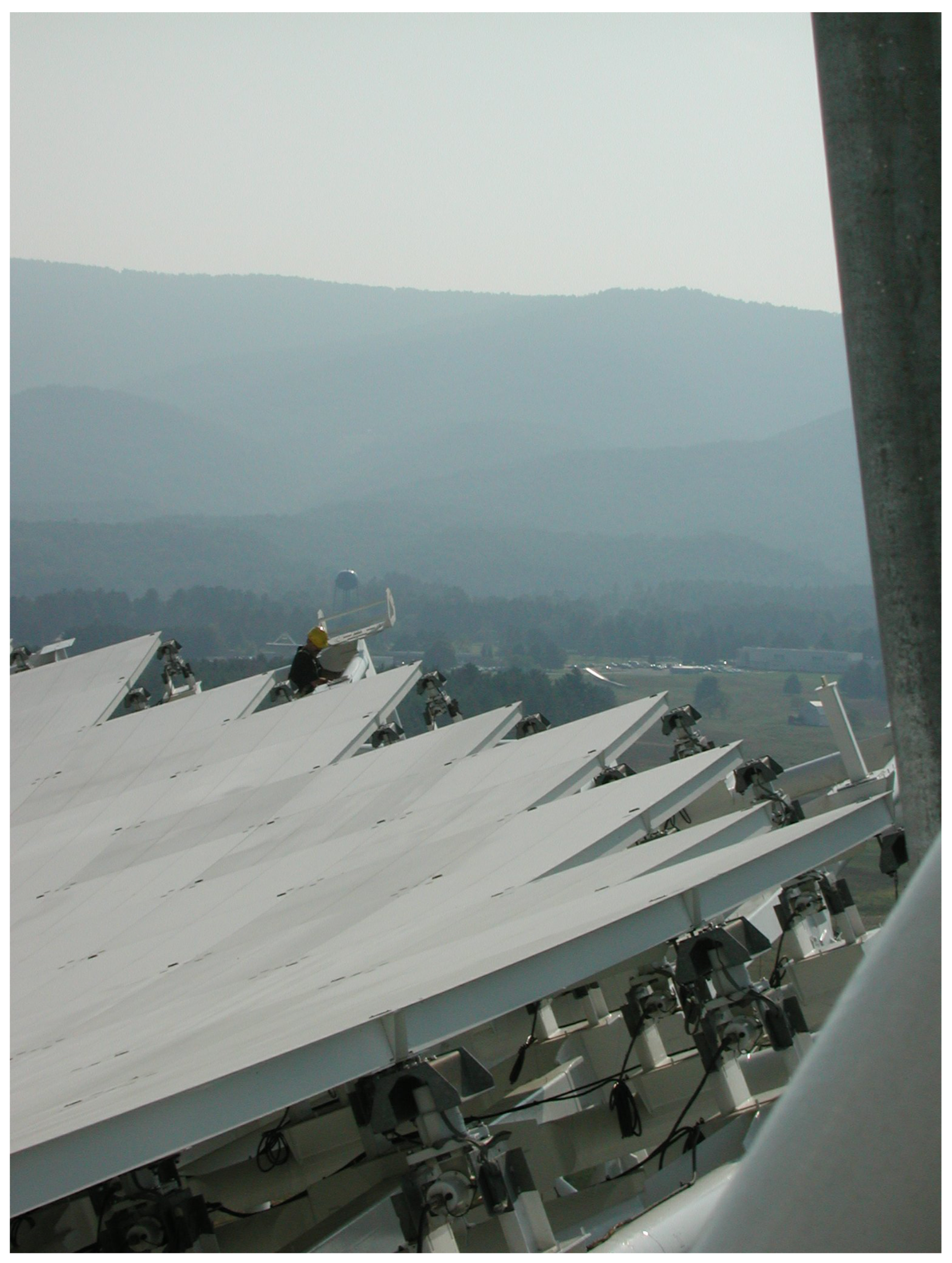
At present, the most common actuation approach used in primary reflector surface control systems of radio telescopes is the electromechanical displacement actuator, typically implemented as a motor-driven ball-screw or lead-screw linear actuator. In terms of structural composition, motor-ball-screw/lead-screw linear actuators generally consist of a servo or stepper motor, transmission and reduction mechanisms, a screw assembly, and position feedback elements. Figure 12 shows a close-up view of an electromechanical actuator installed at the edge of the GBT primary reflector. These actuators provide relatively large effective stroke and load capacity, with mature designs and high operational reliability. Their characteristics facilitate stable displacement closed-loop control and long-term maintenance in large-scale distributed actuator systems, making them a mainstream engineering solution for segmented-reflector radio telescopes [30,76,77,78].
In practical engineering implementation, the GBT 100 m radio telescope employs 2209 electromechanical actuators to adjust the corner nodes of the primary reflector panels. Each actuator provides an effective stroke of approximately 51 mm, a maximum adjustment speed of about 250 μ m/s, and a positioning resolution of approximately 25 μ m [22]. Similarly, the 50 m millimeter-wave radio telescope of the LMT also employs motor-screw-type actuators for primary reflector adjustment. Within a full stroke range of ±5 mm, the actuators achieve a typical RMS positioning error of 2–7 μ m, with peak errors constrained within ±25 μ m, satisfying the engineering requirements of active surface systems for millimeter-wave radio telescopes [79].
Hydraulic actuators have also been applied in representative radio telescope engineering projects.In practical implementation, the primary reflector of the 500 m aperture spherical radio telescope FAST is jointly controlled by more than 2200 hydraulic actuators. Each actuator provides a maximum stroke of approximately 1.2 m, a positioning accuracy of about 0.25 mm, and an operating load range of 10–70 kN [80]. Such systems drive cable-net nodes using hydraulic cylinders to realize large-stroke node displacements and global geometric reconfiguration, providing important engineering reference for the shaping of ultra-large-aperture reflectors.
From an actuation-mechanism perspective, hydraulic actuators adjust the positions of reflector nodes by driving the associated linkage through the extension and retraction of a hydraulic cylinder piston rod. This type of actuator is characterized by a large stroke capability, high load-bearing capacity, and strong resistance to impact and overload conditions. Compared with electromechanical displacement actuators, hydraulic actuators generally exhibit lower system response speed and positioning accuracy, and are associated with higher engineering costs in terms of operation and maintenance, system complexity, and long-term stability.
On the other hand, voice-coil and piezoelectric actuators have evolved into mature technological solutions within active optics and adaptive optics systems for optical telescopes. Benefiting from their high bandwidth and high-resolution characteristics, these actuators effectively support rapid wavefront correction and high-order aberration compensation [81,82]. For radio telescopes, such actuators are more suitably employed as fine-adjustment units within a multistage “coarse-fine” actuation architecture, or regarded as a potential technical option for suppressing local high-frequency disturbances, rather than directly replacing the primary actuators responsible for large-stroke motion and the main structural loads.
Piezoelectric actuators typically generate small deformations directly through the inverse piezoelectric effect of piezoelectric ceramics, and achieve micrometer-level output displacement by means of stacked configurations and compliant amplification mechanisms. When combined with position feedback techniques such as capacitive sensors, nanometer-level positioning resolution can be realized. Although piezoelectric actuators offer advantages including high precision and fast response, their inherently limited stroke and susceptibility to thermal drift make it difficult for them to independently satisfy the stroke requirements of primary reflector surface adjustment in radio telescopes with apertures on the order of 10 m or larger. In recent years, various hybrid actuation schemes have been proposed to overcome the limited stroke of piezoelectric actuators. These approaches include cascaded architectures combining coarse adjustment based on electromechanical lead-screw drives with fine adjustment using piezoelectric actuators, as well as configurations in which piezoelectric motors based on ultrasonic or inertial principles drive lead-screw or differential-thread mechanisms. In active optics systems for optical telescopes, two-stage cascaded actuation architectures that combine coarse and fine adjustment have reached a mature level of engineering implementation. For example, the primary mirror (M1) of the European Southern Observatory (ESO) Extremely Large Telescope (ELT) is equipped with 2394 Positioning Actuator for the Correction of Tip-tilt and focus (PACT) units, each consisting of an electromechanical motor-lead-screw mechanism providing a stroke of approximately 10 mm, together with a piezoelectric fine-adjustment stage offering a stroke of about 10 μ m [83]. A research team at Nanjing University of Aeronautics and Astronautics experimentally validated a cryogenic micro-displacement piezoelectric actuator designed for radio telescope panels. The actuator employs a traveling-wave rotary ultrasonic motor coupled with a differential screw mechanism; under room-temperature conditions, it achieves a stepping accuracy of approximately 1 μ m ± 0.08 μ m [84]. Experimental results indicate that the proposed scheme retains micrometer-level adjustment capability under cryogenic conditions; however, performance evolution and lifetime data of the actuator under long-term continuous operation have not yet been reported. It should be noted that ultrasonic motors operate on friction-based contact mechanisms, whose advantages are primarily manifested in low-speed, high-resolution quasi-static positioning applications rather than in high-speed continuous operating regimes. During prolonged operation, factors such as wear of frictional interfaces and variations in preload conditions may introduce output characteristic drift and changes in backlash, and thus the engineering reliability and long-term stability of such actuators require further systematic validation.
To facilitate an engineering-oriented comparison of the performance characteristics and applicable scenarios of different actuator types, Table 3 summarizes the aforementioned actuators in terms of stroke range, positioning accuracy, load capacity, and their roles in engineering applications. In recent years, single-dish radio telescopes have been evolving toward larger apertures and higher operating frequencies, particularly extending into the submillimeter wavelength regime. Representative next-generation projects, such as the European-led AtLAST and the Japanese-proposed Large Submillimeter Telescope (LST), are both centered on achieving high-frequency, high-efficiency observations under large-aperture conditions [11,85]. Under this development trend, the requirements for surface accuracy and stability of the primary reflector have increased substantially, making the active primary reflector system one of the key engineering measures for ensuring the overall performance of the telescope.
Within an active surface shape control framework, actuators serve as the terminal execution units that directly act on the reflector structure. Their stroke capability, displacement accuracy, long-term stability, and modelability largely determine the effectiveness of surface error compensation and the overall system performance. For future large radio telescope applications, the development of actuators is therefore not primarily driven by the pursuit of high bandwidth or nanometer-level resolution. Instead, greater emphasis is placed on achieving micrometer-level, repeatable positioning accuracy over millimeter-scale strokes, ensuring long-term operational stability, and enabling effective integration with system-level surface control models and control algorithms [86,87].

5.2. Local Actuator Control Methods and Engineering Implementation

In active surface systems, local actuator control does not directly solve the global surface error problem. Instead, it receives target displacement, velocity, or force commands from the higher-level surface control system and tracks these commands under constraints on travel range, speed, load capacity, and operational safety. In practical implementations, the local control scheme is usually influenced by actuator type, position-feedback mechanism, controller sampling rate, communication capability, and operational safety requirements. For most active surface systems in radio telescopes, the primary role of local control is to ensure repeatable actuator positioning accuracy, smooth motion, and operational reliability under low-speed, small-step, and long-duration operating conditions, while feeding back actual position, operating status, and fault information to the higher-level control system.
In an early representative implementation, actuator control in radio-telescope active surface systems was realized using an on/off time-quantized servo scheme. In the 100-m GBT, a simplified on/off time-quantized servo was implemented for each actuator. The controller sampled the actuator position every 100 ms and calculated the required energization duration based on a known velocity model, allowing the actuator to reach the prescribed target position with a positioning resolution of approximately 25 μ m [22]. Such time-quantized control schemes have been validated in large-scale actuator networks, demonstrating the feasibility of dynamic adjustment during telescope operation and supporting the observational requirements of 100-m-class radio telescopes. Nevertheless, their achievable control accuracy, disturbance rejection capability, and dynamic response are inherently limited by the constant-velocity assumption and finite time-quantization resolution.
Apart from the GBT, the Noto 32-m active surface system employs commercially available control electronics driving stepper-motor–lead-screw actuators. Surface adjustments are achieved by issuing target displacement commands, with the actuators attaining a peak positioning accuracy of ±15 μ m across their full travel range [30]. With the application of position sensors, distributed controllers, and electromechanical actuators in active surface systems, the local execution layer has adopted closed-loop tracking schemes centered on position feedback. The LMT introduced a distributed “Bus Box” control architecture, in which each Bus Box locally manages four actuators. Within each Bus Box, a proportional–integral–derivative (PID) control loop is closed using actuator position feedback, and a deadband of 10 μ m is implemented to suppress jitter induced by small disturbances [88].
Under complex operating conditions, actuator friction, backlash, load variations, and low-speed motion-induced vibration can affect local tracking accuracy and motion smoothness. To address these issues, various engineering implementations and research studies have introduced enhancement methods such as trajectory planning, predictive compensation, and robust control. At the 110-m QTT telescope in Xinjiang, an S-curve acceleration algorithm is implemented locally to suppress shocks and low-speed vibrations, enabling the system to achieve a stable control accuracy of ≤5 μ m RMS [89]. The FAST employs a switching grey-prediction PID control method to compensate for nonlinearities and uncertainties, together with an adaptive step-size adjustment mechanism to avoid overshoot and oscillation [68]. Moreover, to address the limitations in control performance of primary-reflector displacement actuators under parameter uncertainties, external disturbances, and complex operating conditions, recent studies have begun to explore algorithms such as Linear Active Disturbance Rejection Control (LADRC) and Quantitative Feedback Theory (QFT) to enhance accuracy, robustness, and disturbance rejection capability [90,91].
In recent years, machine learning and learning-based control methods have been applied in industrial motion control, robotics, and precision positioning for controller parameter tuning, model updating, and nonlinear compensation [92,93,94]. In theory, these approaches offer new avenues for adaptive control and state compensation of active surface actuators. However, mature, publicly documented engineering implementations of machine learning models serving as local closed-loop controllers for radio telescope actuators remain scarce. For large active surface systems intended for long-term operation, learning-based methods still require thorough validation in terms of stability, interpretability, fault tolerance, and long-term reliability.

6. Conclusions

This paper provides a systematic review of active surface shape control technologies for segmented reflectors in large radio telescopes, with emphasis on the main technical routes and representative engineering practices related to surface measurement, actuators and local execution control, and global surface control strategies. Existing studies and engineering implementations indicate that active surface control should not be regarded as the independent development of a single technical component, but rather as a systems-engineering problem that integrates surface error acquisition, structural state sensing, control allocation, and actuator execution. Depending on structural configuration, observing frequency band, surface accuracy target, and available measurement techniques, different telescopes have adopted a variety of implementation schemes, including model-driven compensation, periodic measurement-based correction, sensor-enhanced compensation, and measurement-driven low-frequency adjustment.
For the next generation of large millimetre- and submillimetre-wave single-dish telescopes, the principal challenges in active-surface control are no longer limited to compensating highly repeatable, elevation-dependent gravitational deformation. They also encompass continuous sensing of the complete optical path under complex environmental conditions, coordination among multiple classes of actuators, and constrained dynamic control.
For example, the 50-m aperture and planned observing frequencies of up to approximately 950 GHz of AtLAST impose a half-wavefront error (HWFE) requirement of approximately 20 µm RMS. Homologous structural design and elevation-dependent lookup tables alone cannot adequately compensate for time-varying errors caused by temperature distributions, quasi-static wind loading, and structural drift. Closed-loop metrology and active-adjustment systems are therefore required. For reflector metrology, the central challenge is to achieve micrometre- or even submicrometre-level measurements of relative displacement or optical-path length over spatial scales of approximately 50 m in an open-air environment, with update intervals of only a few seconds. Although real-time photogrammetry can provide updates on timescales of several seconds, its expected accuracy is only 150–500 µm. Existing photogrammetric and laser-tracking methods are therefore unlikely to satisfy the submicrometre measurement requirement of the proposed closed-loop control system. For primary-reflector adjustment, AtLAST is expected to use closed-loop metrology and an active surface to reduce the uncorrected nighttime primary-reflector HWFE from approximately 210 µm RMS to below 20 µm RMS. The active-surface actuators are required to achieve a positioning accuracy of approximately 10 µm, while the closed-loop system must operate with update intervals on the order of seconds. In the panel-segment-level active-surface architecture currently considered for AtLAST, active adjustment is intended primarily to compensate for global structural deformations at low spatial frequencies. Higher-spatial-frequency errors, including panel manufacturing errors, wind-induced deformation of individual panels, and local thermal gradients within reflector tiles, cannot readily be corrected at this level of active control. These errors must instead be limited through appropriate choices of panel materials and segment dimensions, manufacturing and installation accuracy, support-structure design, and thermal design. From a control perspective, excess-path-length (EPL) measurements obtained from a limited number of sensing points provide only spatially discrete and sparse information about the wavefront. Moreover, not all measurable errors can be corrected by the available actuation mechanisms. The controllable modes of the system are jointly determined by the sensor layout, the actuator-to-sensor measurement or influence matrix, and the available actuation degrees of freedom. Errors of different orders and spatial frequencies must therefore be appropriately allocated among the telescope mount axes, rigid-body adjustment of the subreflector, and active deformation of the primary reflector. Because large optical components respond relatively slowly, closed-loop design must also account for structural natural frequencies, metrology and digital-control delays, model uncertainty, actuator saturation, and coupling among multiple control loops [11,95,96].
To address these challenges, coordinated optimization is required across surface metrology, structural modelling, control allocation, and actuator execution. On the one hand, surface measurement technologies need to achieve a more effective balance among measurement accuracy, spatial coverage, update frequency, environmental adaptability, and data-processing latency, thereby enhancing the system’s ability to sense error sources such as thermal gradients, wind-induced disturbances, and long-term structural drift. On the other hand, actuator systems must not only provide the stroke and load capacity required for structural compensation, but also offer reliable support in terms of micrometre-level repeatable positioning accuracy, long-term stability, status feedback, and fault-safe operation. On this basis, control and compensation strategies should further integrate structural models, surface measurements, and state-sensing information, while enabling robust control allocation and surface compensation under actuator constraints.
In recent years, machine learning methods have begun to be explored in studies related to active surface shape control in radio telescopes, primarily for tasks such as rapid global or local surface prediction, surrogate finite-element modeling, sparse-sensor data reconstruction, and analysis of surface measurement data. These approaches can improve the efficiency of complex structural deformation estimation and multi-source data processing. However, their error bounds, generalization capability, interpretability, stability, and fault tolerance under long-term operational conditions remain to be fully validated. Consequently, at the current stage, machine learning methods are more suitable as auxiliary tools for structural modeling, measurement data processing, and control parameter optimization, rather than as mature approaches capable of directly replacing physical models and engineering control frameworks.
Overall, the development of active surface shape control technologies for segmented reflectors in large radio telescopes is shifting from performance improvement in individual components toward system-level coordinated optimization of surface metrology, structural modelling, control allocation, and actuator reliability. By reviewing the existing technical framework and representative engineering practices, this paper provides a reference for the design and optimization of active surface control schemes for future large millimetre- and submillimetre-wave radio telescopes. As the planning and construction of next-generation large-aperture, high-frequency telescopes continue to advance, establishing active surface control systems that are verifiable, maintainable, and capable of long-term stable operation will become an essential technical foundation for ensuring their high-frequency observing performance.

Author Contributions

Conceptualization, R.W. and L.D.; methodology, R.W.; investigation, R.W.; formal analysis, R.W.; data curation, R.W.; writing—original draft preparation, R.W.; writing—review and editing, R.W. and L.D.; visualization, R.W.; supervision, L.D.; project administration, L.D.; funding acquisition, L.D. All authors have read and agreed to the published version of the manuscript.

Funding

This research was funded by the National Natural Science Foundation of China (Grant No. 12141305).

Data Availability Statement

No new data were created or analyzed in this study. Data sharing is not applicable to this article.

Acknowledgments

The authors gratefully acknowledge Hong Shen for helpful discussions and support during this work.

Conflicts of Interest

The authors declare no conflicts of interest. The funders had no role in the design of the study; in the collection, analyses, or interpretation of data; in the writing of the manuscript; or in the decision to publish the results.

References

  1. Wilson, T.L. Introduction to Millimeter/Sub-millimeter Astronomy. In Millimeter Astronomy: Saas-Fee Advanced Course 38. Swiss Society for Astrophysics and Astronomy; Dessauges-Zavadsky, M., Pfenniger, D., Eds.; Springer: Berlin/Heidelberg, Germany, 2018; pp. 1–109. [Google Scholar] [CrossRef] [Scilit]
  2. Blain, A.W.; Smail, I.; Ivison, R.J.; Kneib, J.P.; Frayer, D.T. Submillimeter galaxies. Phys. Rep. 2002, 369, 111–176. [Google Scholar] [CrossRef] [Scilit]
  3. Williams, J.P.; Cieza, L.A. Protoplanetary Disks and Their Evolution. Annu. Rev. Astron. Astrophys. 2011, 49, 67–117. [Google Scholar] [CrossRef] [Scilit]
  4. Bergin, E.A.; Tafalla, M. Cold Dark Clouds: The Initial Conditions for Star Formation. Annu. Rev. Astron. Astrophys. 2007, 45, 339–396. [Google Scholar] [CrossRef] [Scilit]
  5. Radford, S.J.; Holdaway, M.A. Atmospheric conditions at a site for submillimeter-wavelength astronomy. In SPIE Advanced Technology MMW, Radio, and Terahertz Telescopes; Phillips, T.G., Ed.; SPIE: Bellingham, WA, USA, 1998; Volume 3357, pp. 486–494. [Google Scholar] [CrossRef] [Scilit]
  6. Tremblin, P.; Schneider, N.; Minier, V.; Durand, G.A.; Urban, J. Worldwide site comparison for submillimetre astronomy. Astron. Astrophys. 2012, 548, A65. [Google Scholar] [CrossRef] [Scilit]
  7. Stanimirovic, S. Short-Spacings Correction from the Single-Dish Perspective. arXiv 2002, arXiv:astro-ph/0205329. [Google Scholar] [CrossRef] [Scilit]
  8. Koda, J.; Teuben, P.; Sawada, T.; Plunkett, A.; Fomalont, E. Total Power Map to Visibilities (TP2VIS): Joint Deconvolution of ALMA 12 m, 7 m, and Total Power Array Data. Publ. Astron. Soc. Pac. 2019, 131, 054505. [Google Scholar] [CrossRef] [Scilit]
  9. Olmi, L.; Migoni, C.; Murgia, M.; Nesti, R.; Poppi, S. First demonstration of super-resolution with a single-aperture radio telescope. Exp. Astron. 2026, 61, 5. [Google Scholar] [CrossRef] [Scilit]
  10. Olmi, L.; Bolli, P.; Nesti, R. Simulations of Angular Super-Resolution with the Active Surface of the Sardinia Radio Telescope. In Proceedings of the 2022 3rd URSI Atlantic and Asia Pacific Radio Science Meeting (AT-AP-RASC), Gran Canaria, Spain, 29 May–3 June 2022; pp. 1–3. [Google Scholar] [CrossRef] [Scilit]
  11. Mroczkowski, T.; Gallardo, P.A.; Timpe, M.; Kiselev, A.; Groh, M.; Kaercher, H.; Reichert, M.; Cicone, C.; Puddu, R.; Dubois-dit-Bonclaude, P.; et al. The conceptual design of the 50-meter Atacama Large Aperture Submillimeter Telescope (AtLAST). Astron. Astrophys. 2025, 694, A142. [Google Scholar] [CrossRef] [Scilit]
  12. Adam, R.; Adane, A.; Ade, P.A.R.; André, P.; Andrianasolo, A.; Aussel, H.; Beelen, A.; Benoît, A.; Bideaud, A.; Billot, N.; et al. The NIKA2 large-field-of-view millimetre continuum camera for the 30 m IRAM telescope. Astron. Astrophys. 2018, 609, A115. [Google Scholar] [CrossRef] [Scilit]
  13. Booth, M.; Klaassen, P.; Cicone, C.; Mroczkowski, T.; Cordiner, M.A.; Di Mascolo, L.; Johnstone, D.; van Kampen, E.; Lee, M.M.; Liu, D.; et al. AtLAST Science Overview Report. arXiv 2024, arXiv:2407.01413. [Google Scholar] [CrossRef] [Scilit]
  14. Ruze, J. Antenna tolerance theory—A review. Proc. IEEE 1966, 54, 633–640. [Google Scholar] [CrossRef] [Scilit]
  15. Wilson, T.L.; Rohlfs, K.; Hüttemeister, S. Tools of Radio Astronomy; Springer: Berlin/Heidelberg, Germany, 2013. [Google Scholar] [CrossRef] [Scilit]
  16. Schloerb, F.P.; Souccar, K.; Gale, D.M.; Huerta, A.L.; Hughes, D.H.; Wilson, G.W. LASERS: A real time antenna metrology system for the Large Millimeter Telescope. In Proceedings of the Advances in Optical and Mechanical Technologies for Telescopes and Instrumentation V; Navarro, R., Geyl, R., Eds.; International Society for Optics and Photonics, SPIE: Bellingham, WA, USA, 2022; Volume 12188, p. 1218819. [Google Scholar] [CrossRef] [Scilit]
  17. Nikolic, B.; Hills, R.E.; Richer, J.S. Measurement of antenna surfaces from in- and out-of-focus beam maps using astronomical sources. Astron. Astrophys. 2007, 465, 679–683. [Google Scholar] [CrossRef] [Scilit]
  18. Hunter, T.R.; Schwab, F.R.; White, S.D.; Ford, J.M.; Ghigo, F.D.; Maddalena, R.J.; Mason, B.S.; Nelson, J.D.; Prestage, R.M.; Ray, J.; et al. Holographic Measurement and Improvement of the Green Bank Telescope Surface. Publ. Astron. Soc. Pac. 2011, 123, 1087–1099. [Google Scholar] [CrossRef] [Scilit]
  19. Ries, P.; Hunter, T.R.; Constantikes, K.T.; Brandt, J.J.; Ghigo, F.D.; Mason, B.S.; Prestage, R.M.; Ray, J.; Schwab, F.R. Measuring and Correcting Wind-Induced Pointing Errors of the Green Bank Telescope Using an Optical Quadrant Detector. Publ. Astron. Soc. Pac. 2011, 123, 682. [Google Scholar] [CrossRef] [Scilit]
  20. Hachenberg, O.; Grahl, B.; Wielebinski, R. The 100-meter radio telescope at Effelsberg. Proc. IEEE 1973, 61, 1288–1295. [Google Scholar] [CrossRef] [Scilit]
  21. Godwin, M.P.; Schoessow, E.P.; Grahl, B.H. Improvement of the Effelsberg 100 meter telescope based on holographic reflector surface measurement. Astron. Astrophys. 1986, 167, 390–394. [Google Scholar]
  22. Lacasse, R.J. Green Bank Telescope active surface system. In Proceedings of the Telescope Control Systems III; Lewis, H., Ed.; Society of Photo-Optical Instrumentation Engineers (SPIE) Conference Series; SPIE: Bellingham, WA, USA, 1998; Volume 3351, pp. 310–319. [Google Scholar] [CrossRef] [Scilit]
  23. Prestage, R.M.; Constantikes, K.T.; Hunter, T.R.; King, L.J.; Lacasse, R.J.; Lockman, F.J.; Norrod, R.D. The Green Bank Telescope. Proc. IEEE 2009, 97, 1382–1390. [Google Scholar] [CrossRef] [Scilit]
  24. Hughes, D.H.; Schloerb, F.P.; Aretxaga, I.; Castillo-Domínguez, E.; Chávez Dagostino, M.; Colín, E.; Erickson, N.; Ferrusca Rodriguez, D.; Gale, D.M.; Gómez-Ruiz, A.; et al. The Large Millimeter Telescope (LMT) Alfonso Serrano: Current status and telescope performance. In Proceedings of the Ground-Based and Airborne Telescopes VIII; Marshall, H.K., Spyromilio, J., Usuda, T., Eds.; Society of Photo-Optical Instrumentation Engineers (SPIE) Conference Series; SPIE: Bellingham, WA, USA, 2020; Volume 11445, p. 1144522. [Google Scholar] [CrossRef] [Scilit]
  25. Prandoni, I.; Murgia, M.; Tarchi, A.; Burgay, M.; Castangia, P.; Egron, E.; Govoni, F.; Pellizzoni, A.; Ricci, R.; Righini, S.; et al. The Sardinia Radio Telescope: From a technological project to a radio observatory. Astron. Astrophys. 2017, 608, A40. [Google Scholar] [CrossRef] [Scilit]
  26. Salas, P.; Marganian, P.; Brandt, J.; Shelton, J.; Sharp, N.; Jensen, L.; Bloss, M.; Beaudet, C.; Egan, D.; Sizemore, N.; et al. Evaluating a strategy for measuring deformations of the primary reflector of the Green Bank telescope using a terrestrial laser scanner. Adv. Control Appl. 2022, 4, e99. [Google Scholar] [CrossRef] [Scilit]
  27. Bolli, P.; Orlati, A.; Stringhetti, L.; Orfei, A.; Righini, S.; Ambrosini, R.; Bartolini, M.; Bortolotti, C.; Buffa, F.; Buttu, M.; et al. Sardinia Radio Telescope: General Description, Technical Commissioning and First Light. J. Astron. Instrum. 2015, 04, 1550008. [Google Scholar] [CrossRef] [Scilit]
  28. Wang, N.; Xu, Q.; Ma, J.; Liu, Z.; Liu, Q.; Zhang, H.; Pei, X.; Chen, M.; Manchester, R.N.; Lee, K.; et al. The Qitai radio telescope. Sci. China Phys. Mech. Astron. 2023, 66, 289512. [Google Scholar] [CrossRef] [Scilit]
  29. Gale, D.M. Experience of primary surface alignment for the LMT using a laser tracker in a non-metrology environment. In Proceedings of the Ground-Based and Airborne Telescopes IV; Stepp, L.M., Gilmozzi, R., Hall, H.J., Eds.; International Society for Optics and Photonics, SPIE: Bellingham, WA, USA, 2012; Volume 8444, p. 844453. [Google Scholar] [CrossRef] [Scilit]
  30. Orfei, A.; Morsiani, M.; Zacchiroli, G.; Maccaferri, G.; Roda, J.; Fiocchi, F. The Active Surface System on the Noto Radio Telescope. In Proceedings of the 6th European VLBI Network Symposium on New Developments in VLBI Science and Technology; Ros, E., Porcas, R.W., Lobanov, A.P., Zensus, J.A., Eds.; Max-Planck-Institut für Radiostronomie (MPIfR): Bonn, Germany, 2002; p. 13. [Google Scholar]
  31. Stochino, F.; Cazzani, A.; Poppi, S.; Turco, E. Sardinia radio telescope finite element model updating by means of photogrammetric measurements. Math. Mech. Solids 2017, 22, 885–901. [Google Scholar] [CrossRef] [Scilit]
  32. Zhang, H.; Li, G.; Zhang, Y. Research on Active Surface Based on Angle Feedback between Adjacent Reflector Panels. Sci. Sin. Phys. Mech. Astron. 2019, 49, 099507. [Google Scholar] [CrossRef] [Scilit]
  33. Puttock, M.; Minnett, H. Instrument for rapid measurement of surface deformations of a 210ft radio telescope. Proc. Inst. Electr. Eng. 1966, 113, 1723–1730. [Google Scholar] [CrossRef] [Scilit]
  34. Greve, A.; Harth, W. Laser-diode distance meter in a KERN DKM 3A theodolite. Appl. Opt. 1984, 23, 2982–2984. [Google Scholar] [CrossRef] [Scilit] [PubMed]
  35. Baars, J.; Greve, A.; Hein, H.; Morris, D.; Penalver, J.; Thum, C. Design parameters and measured performance of the IRAM 30-m Millimeter Radio Telescope. Proc. IEEE 1994, 82, 687–696. [Google Scholar] [CrossRef] [Scilit]
  36. Booth, R.S.; Delgado, G.; Hagstrom, M.; Johansson, L.E.B.; Murphy, D.C.; Olberg, M.; Whyborn, N.D.; Greve, A.; Hansson, B.; Lindstrom, C.O.; et al. The Swedish-ESO submillimeter telescope (SEST). Astron. Astrophys. 1989, 216, 315–324. [Google Scholar]
  37. Maisano, D.A.; Mastrogiacomo, L.; Franceschini, F.; Capizzi, S.; Pischedda, G.; Laurenza, D.; Gomiero, G.; Manca, G. Dimensional measurements in the shipbuilding industry: On-site comparison of a state-of-the-art laser tracker, total station and laser scanner. Prod. Eng. 2023, 17, 625–642. [Google Scholar] [CrossRef] [Scilit]
  38. Zhu, L. Introduction of measurement and control technology of FAST. In Proceedings of the Ground-Based and Airborne Telescopes VII; Marshall, H.K., Spyromilio, J., Eds.; Society of Photo-Optical Instrumentation Engineers (SPIE) Conference Series; SPIE: Bellingham, WA, USA, 2018; Volume 10700, p. 107001V. [Google Scholar] [CrossRef] [Scilit]
  39. Zobrist, T.L.; Burge, J.H.; Martin, H.M. Laser tracker surface measurements of the 8.4m GMT primary mirror segment. In Proceedings of the Optical Manufacturing and Testing VIII; Burge, J.H., Fähnle, O.W., Williamson, R., Eds.; International Society for Optics and Photonics: Bellingham, WA, USA, 2009; Volume 7426, p. 742613. [Google Scholar] [CrossRef] [Scilit]
  40. Rakich, A. Using a laser tracker for active alignment on the Large Binocular Telescope. In Proceedings of the Ground-Based and Airborne Telescopes IV; Stepp, L.M., Gilmozzi, R., Hall, H.J., Eds.; Society of Photo-Optical Instrumentation Engineers (SPIE) Conference Series; SPIE: Bellingham, WA, USA, 2012; Volume 8444, p. 844454. [Google Scholar] [CrossRef] [Scilit]
  41. Holst, C.; Schunck, D.; Nothnagel, A.; Haas, R.; Wennerbäck, L.; Olofsson, H.; Hammargren, R.; Kuhlmann, H. Terrestrial Laser Scanner Two-Face Measurements for Analyzing the Elevation-Dependent Deformation of the Onsala Space Observatory 20-m Radio Telescope’s Main Reflector in a Bundle Adjustment. Sensors 2017, 17, 1833. [Google Scholar] [CrossRef] [Scilit] [PubMed]
  42. Hall, R.; Goldman, M.A.; Parker, D.H.; Payne, J.M. Measurement program for the Green Bank Telescope. In Proceedings of the Advanced Technology MMW, Radio, and Terahertz Telescopes; Phillips, T.G., Ed.; International Society for Optics and Photonics, SPIE: Bellingham, WA, USA, 1998; Volume 3357, pp. 265–276. [Google Scholar] [CrossRef] [Scilit]
  43. Prestage, R.M.; Constantikes, K.T.; Balser, D.S.; Condon, J.J. The GBT precision telescope control system. In Proceedings of the Ground-Based Telescopes; Oschmann, J.M., Jr., Ed.; International Society for Optics and Photonics, SPIE: Bellingham, WA, USA, 2004; Volume 5489, pp. 1029–1040. [Google Scholar] [CrossRef] [Scilit]
  44. Bruno, N.; Giacomini, A.; Roncella, R.; Thoeni, K. INFLUENCE OF ILLUMINATION CHANGES ON IMAGE-BASED 3D SURFACE RECONSTRUCTION. Int. Arch. Photogramm. Remote Sens. Spat. Inf. Sci. 2021, XLIII-B2-2021, 701–708. [Google Scholar] [CrossRef] [Scilit]
  45. Buffa, F.; Causin, A.; Cazzani, A.; Poppi, S.; Sanna, G.; Solci, M.; Stochino, F.; Turco, E. The Sardinia Radio Telescope: A comparison between close-range photogrammetry and finite element models. Math. Mech. Solids 2017, 22, 1005–1026. [Google Scholar] [CrossRef] [Scilit]
  46. Venter, M.; Garcia-Pérez, Ó.; Tercero-Martínez, F.; López-Pérez, J.A.; Malan, S.; Mey, P. Performance of the VGOS Radio Telescope with As-built Feed and Geometry Using Electromagnetic Simulations. In Proceedings of the 2023 17th European Conference on Antennas and Propagation (EuCAP), Florence, Italy, 26–31 March 2023; pp. 1–4. [Google Scholar] [CrossRef] [Scilit]
  47. Li, W.M.; Zhou, L.J. A preliminary study on photogrammetry for the FAST main reflector measurement. Res. Astron. Astrophys. 2021, 21, 156. [Google Scholar] [CrossRef] [Scilit]
  48. Cortes-Medellin, G.; Lovell, A.J.; Enriquez, R.; Smith, D.R. Using an active primary surface to correct for low-order manufacturing errors in secondary mirrors of large reflector antennas. In Proceedings of the Astronomical Structures and Mechanisms Technology; Antebi, J., Lemke, D., Eds.; International Society for Optics and Photonics, SPIE: Bellingham, WA, USA, 2004; Volume 5495, pp. 126–136. [Google Scholar] [CrossRef] [Scilit]
  49. Morris, D.; Baars, J.W.M.; Hein, H.; Steppe, H.; Thum, C. Radio-holographic reflector measurement of the 30-m millimeter radio telescope at 22 GHz with a cosmic signal source. Astron. Astrophys. 1988, 203, 399–406. [Google Scholar]
  50. Baars, J.W.M.; Lucas, R.; Mangum, J.G.; Lopez-Perez, J.A. Near-Field Radio Holography of Large Reflector Antennas. IEEE Antennas Propag. Mag. 2007, 49, 24–41. [Google Scholar] [CrossRef]
  51. Balasubramanyam, R.; Venkatesh, S.; Raju, S.B. 12 GHz Radio-Holographic Surface Measurements of the RRI 10.4 m Telescope. In Proceedings of the Low-Frequency Radio Universe; Saikia, D.J., Green, D.A., Gupta, Y., Venturi, T., Eds.; Astronomical Society of the Pacific Conference Series 2009; Astronomical Society of the Pacific: San Francisco, CA, USA, 2009; Volume 407, p. 434. [Google Scholar] [CrossRef] [Scilit]
  52. Romero, C.F.; Varela, F.R.; Iragüen, B.G.; López-Pérez, J.A. Fast Surface Error Diagnosis for Radiotelescopes Using Linearized Microwave Holography. IEEE Trans. Antennas Propag. 2025, 73, 3527–3536. [Google Scholar] [CrossRef] [Scilit]
  53. Zhang, X.; Liu, W.; Zuo, Y.; Lan, Y.; Lou, Z.; Qian, Y.; Chen, B. Simultaneous Multifrequency Near-Field Radio Holography of Reflector Antennas. IEEE Trans. Antennas Propag. 2024, 72, 6242–6250. [Google Scholar] [CrossRef] [Scilit]
  54. Cassanelli, T.; Bach, U.; Winkel, B.; Kraus, A. Out-of-focus holography at the Effelsberg telescope. Systematic measurements of the surface of a 100 m telescope using OOF holography. Astron. Astrophys. 2024, 687, A27. [Google Scholar] [CrossRef] [Scilit]
  55. Tamura, Y.; Kawabe, R.; Fukasaku, Y.; Kimura, K.; Ueda, T.; Taniguchi, A.; Okada, N.; Ogawa, H.; Hashimoto, I.; Minamidani, T.; et al. Wavefront sensor for millimeter/submillimeter-wave adaptive optics based on aperture-plane interferometry. In Proceedings of the Ground-Based and Airborne Telescopes VIII; Marshall, H.K., Spyromilio, J., Usuda, T., Eds.; International Society for Optics and Photonics, SPIE: Bellingham, WA, USA, 2020; Volume 11445, p. 114451N. [Google Scholar] [CrossRef] [Scilit]
  56. Nakano, S.; Tamura, Y.; Taniguchi, A.; Okumura, S.; Kawabe, R.; Okada, N.; Nakamura, T.; Fukasaku, Y. Characterization of sensitivity and responses of a 2-element prototype wavefront sensor for millimeter-wave adaptive optics attached to the Nobeyama 45 m Telescope. In Proceedings of the Adaptive Optics Systems VIII; Schreiber, L., Schmidt, D., Vernet, E., Eds.; International Society for Optics and Photonics, SPIE: Bellingham, WA, USA, 2022; Volume 12185, p. 121856Z. [Google Scholar] [CrossRef] [Scilit]
  57. Greve, A. Reflector surface measurements of the IRAM 30-m radio telescope. Int. J. Infrared Millim. Waves 1986, 7, 121–135. [Google Scholar] [CrossRef] [Scilit]
  58. Li, Z.C.; Li, G.Y.; Tang, T.S.; Zhang, G.Y. Electronic Multi-theodolite Measuring System Applied in the Precision Installation of a Large Antenna. Hydrogr. Surv. Charting 2005, 25, 26–30. [Google Scholar]
  59. Sarti, P.; Vittuari, L.; Abbondanza, C. Laser Scanner and Terrestrial Surveying Applied to Gravitational Deformation Monitoring of Large VLBI Telescopes’ Primary Reflector. J. Surv. Eng. 2009, 135, 136–148. [Google Scholar] [CrossRef] [Scilit]
  60. Gale, D.M.; Leon-Huerta, A.; Cuevas, L.C.; Santos, D.C.; Ríos, E.H.; Álvarez, M.L.; Sosa, E.T.; Torres, C.T.; Sánchez-Argüelles, D.; Narayanan, G.; et al. Mapping the Large Millimeter Telescope primary reflector using photogrammetry: A first comparison with 12 GHz holography. In Proceedings of the Advances in Optical and Mechanical Technologies for Telescopes and Instrumentation II; Navarro, R., Burge, J.H., Eds.; International Society for Optics and Photonics, SPIE: Bellingham, WA, USA, 2016; Volume 9912, p. 99124F. [Google Scholar] [CrossRef] [Scilit]
  61. Wang, J.; Zuo, X.; Kesteven, M.; Zhao, R.; Yu, L.; Jiang, Y.; Gou, W.; Jiang, Y.; Guo, W. TM65 m Radio Telescope Microwave Holography. Sci. Sin. Phys. Mech. Astron. 2017, 47, 099502. [Google Scholar] [CrossRef] [Scilit]
  62. Nikolic, B.; Prestage, R.M.; Balser, D.S.; Chandler, C.J.; Hills, R.E. Out-of-focus holography at the Green Bank Telescope. Astron. Astrophys. 2007, 465, 685–693. [Google Scholar] [CrossRef] [Scilit]
  63. Buffa, F.; Serra, G.; Poppi, S.; Egron, E.; Murgia, M.; Pinna, A. Out-of-focus holography at the Sardinia Radio Telescope. In Proceedings of the Ground-Based and Airborne Telescopes VIII; Marshall, H.K., Spyromilio, J., Usuda, T., Eds.; International Society for Optics and Photonics, SPIE: Bellingham, WA, USA, 2020; Volume 11445, p. 114456G. [Google Scholar] [CrossRef] [Scilit]
  64. Lian, P.; Wang, C.; Xue, S.; Xu, Q.; Wang, N.; Xiang, B.; Shi, Y.; Jia, Y. Panel Adjustment and Error Analysis for a Large Active Main Reflector Antenna by Using the Panel Adjustment Matrix. IEEE Trans. Antennas Propag. 2021, 69, 6351–6363. [Google Scholar] [CrossRef] [Scilit]
  65. Wang, J.Q.; Sun, Z.X.; Fu, L.; Li, J.L.; Yu, L.F.; Jiang, Y.C.; Jiang, Y.B.; Gou, W.; Hu, W.; Zhao, R.B.; et al. Research on actuator distribution and panels for a radio telescope. Res. Astron. Astrophys. 2021, 21, 157. [Google Scholar] [CrossRef] [Scilit]
  66. Sun, Z.; Wang, J.; Yu, L.; Zhang, Z.; Wang, G. Research on the Adjustment Method of the Main Reflector Surface of Large Radio Telescopes. Acta Astron. Sin. 2024, 65, 44–54. (In Chinese) [Google Scholar] [CrossRef]
  67. Wang, Y.; Wang, Q.; Zhu, L.; Wu, M.; Jiang, P.; Gan, H.; Zhang, Z.; Yang, L. The operation control and data acquisition of the actuators of FAST main reflector. In Society of Photo-Optical Instrumentation Engineers (SPIE) Conference Series; Marshall, H.K., Spyromilio, J., Eds.; Proceedings of the Ground-Based and Airborne Telescopes VII; International Society for Optics and Photonics, SPIE: Bellingham, WA, USA, 2018; Volume 10700, p. 107005Q. [Google Scholar] [CrossRef] [Scilit]
  68. Xiao, J.; Liu, Q.; Wang, G.; Ji, J. Theoretical and Experimental Analysis of the Hydraulic Actuator Used in the Active Reflector System. Math. Probl. Eng. 2018, 2018, 1–13. [Google Scholar] [CrossRef] [Scilit]
  69. Tofani, G.; Alvito, G.; Ambrosini, R.; Bolli, P.; Bortolotti, C.; Bruca, L.; Buffa, F.; Cattani, A.; Comoretto, G.; Cremonini, A.; et al. Status of the Sardinia Radio Telescope project. In Proceedings of the Ground-Based and Airborne Telescopes II; Stepp, L.M., Gilmozzi, R., Eds.; International Society for Optics and Photonics, SPIE: Bellingham, WA, USA, 2008; Volume 7012, p. 70120F. [Google Scholar] [CrossRef] [Scilit]
  70. Leong, M.; Peng, R.; Yoshida, H.; Chamberlin, R.; Phillips, T.G. A Caltech Submillimeter Observatory Active Optics System. In Proceedings of the Submillimeter Astrophysics and Technology: A Symposium Honoring Thomas G. Phillips; Lis, D.C., Vaillancourt, J.E., Goldsmith, P.F., Bell, T.A., Scoville, N.Z., Zmuidzinas, J., Eds.; Astronomical Society of the Pacific Conference Series; Astronomical Society of the Pacific: San Francisco, CA, USA, 2009; Volume 417, p. 131. [Google Scholar]
  71. Baars, J.W.M.; Karcher, H.J. Design features of the Large Millimeter Telescope (LMT). In Proceedings of the IEEE Antennas and Propagation Society International Symposium. 1999 Digest. Held in Conjunction With: USNC/URSI National Radio Science Meeting, Orlando, FL, USA, 1–16 July 1999; Volume 3, pp. 1544–1547. [Google Scholar] [CrossRef] [Scilit]
  72. Altenhoff, W.J.; Baars, J.W.M.; Wink, J.E.; Downes, D. Observations of anomalous refraction at radio wavelengths. Astron. Astrophys. 1987, 184, 381–385. [Google Scholar]
  73. Olmi, L. Systematic observations of anomalous refraction at millimeter wavelengths. Astron. Astrophys. 2001, 374, 348–357. [Google Scholar] [CrossRef] [Scilit]
  74. Zhang, Z.; Ye, Q.; Fu, L.; Liu, Q.; Meng, G. Calculating real-time surface deformation for large active surface radio antennas using a graph neural network. Astron. Tech. Instrum. 2024, 1, 267–274. [Google Scholar] [CrossRef] [Scilit]
  75. Cheng, W.; Wang, B.; Li, Z. An accurate model for active surface system of milliter/submilliter wave radio telescope. In Proceedings of the 2024 4th International Conference on Electrical Engineering and Control Science (IC2ECS), Nanjing, China, 27–29 December 2024; pp. 791–794. [Google Scholar] [CrossRef] [Scilit]
  76. Zhang, D.; Zhao, R.B.; Yan, Z.; Shang-Guan, W.H.; Ye, Q.; Shen, Z.Q.; Liu, Q.H.; Wang, J.Q.; Fu, L.; Zhang, C.Y.; et al. Distributed Control Software for the Active Surface System of Tian-ma Radio Telescope. Res. Astron. Astrophys. 2023, 23, 115024. [Google Scholar] [CrossRef] [Scilit]
  77. Dong, J.; Jin, H.; Ye, Q.; Shen, Z.; Liu, Q.; Fu, L. The active surface control system for the Tian Ma Telescope. In Proceedings of the Software and Cyberinfrastructure for Astronomy IV; Chiozzi, G., Guzman, J.C., Eds.; Society of Photo-Optical Instrumentation Engineers (SPIE) Conference Series; SPIE: Bellingham, WA, USA, 2016; Volume 9913, p. 991306. [Google Scholar] [CrossRef] [Scilit]
  78. Wang, C.; Li, H.; Ying, K.; Xu, Q.; Wang, N.; Duan, B.; Gao, W.; Xiao, L.; Duan, Y. Active Surface Compensation for Large Radio Telescope Antennas. Int. J. Antennas Propag. 2018, 2018, 3903412. [Google Scholar] [CrossRef] [Scilit]
  79. Smith, D.R.; Souccar, K.; Montalvo, G.; Magaña, C.A.; Rebollar, J.L.H.; Hernández, J.L.; Nolasco, M.E.M.; Fumi, P.; Anaclerio, E.; Gallieni, D. Field testing and performance characterization of the production LMT/GTM active surface actuators. In Proceedings of the Advances in Optical and Mechanical Technologies for Telescopes and Instrumentation III; Navarro, R., Geyl, R., Eds.; SPIE: Bellingham, WA, USA, 2018; Volume 10706, p. 107066Q. [Google Scholar] [CrossRef] [Scilit]
  80. Wang, J.Z. Research and Manufacture of Hydraulic Actuator System for Five Hundred Meters Aperture Spherical Telescope. Hydraul. Pneum. Seals 2017, 37, 1–4. [Google Scholar]
  81. Tyson, R.K.; Frazier, B.W. Principles of Adaptive Optics, 5th ed.; CRC Press: Boca Raton, FL, USA, 2022. [Google Scholar] [CrossRef] [Scilit]
  82. Madec, P.Y. Overview of deformable mirror technologies for adaptive optics and astronomy. In Proceedings of the Adaptive Optics Systems III; Ellerbroek, B.L., Marchetti, E., Véran, J.P., Eds.; Society of Photo-Optical Instrumentation Engineers (SPIE) Conference Series; SPIE: Bellingham, WA, USA, 2012; Volume 8447, p. 844705. [Google Scholar] [CrossRef] [Scilit]
  83. Reinacher, A.; Sedghi, B.; Dimmler, M.; Andolfato, L. Advancements of the ELT M1 Figure Control Loop: Edge Sensor Fault Detection and Management of Actuator Non-linearities in a Large MIMO System. In Proceedings of the Ground-Based and Airborne Telescopes X; Marshall, H.K., Spyromilio, J., Usuda, T., Eds.; SPIE: Bellingham, WA, USA, 2024; Volume 13094, p. 130941D. [Google Scholar] [CrossRef] [Scilit]
  84. Deng, Y.; Jiang, Z.; Jin, J. Research on a cryogenic micro-displacement piezoelectric actuator for the radio telescope panels. In Proceedings of the 2017 Symposium on Piezoelectricity, Acoustic Waves, and Device Applications (SPAWDA), Chengdu, China, 27–30 October 2017; pp. 490–494. [Google Scholar] [CrossRef] [Scilit]
  85. Kohno, K.; Kawabe, R.; Tamura, Y.; Endo, A.; Baselmans, J.J.A.; Karatsu, K.; Inoue, A.K.; Moriwaki, K.; Hayatsu, N.H.; Yoshida, N.; et al. Large format imaging spectrograph for the Large Submillimeter Telescope (LST). In Proceedings of the Millimeter, Submillimeter, and Far-Infrared Detectors and Instrumentation for Astronomy X; Zmuidzinas, J., Gao, J.R., Eds.; Society of Photo-Optical Instrumentation Engineers (SPIE) Conference Series; SPIE: Bellingham, WA, USA, 2020; Volume 11453, p. 114530N. [Google Scholar] [CrossRef] [Scilit]
  86. Wilson, R.N. Reflecting Telescope Optics II: Manufacture, Testing, Alignment, Modern Techniques, 1st ed.; Astronomy and Astrophysics Library, Springer: Berlin/Heidelberg, Germany, 1999. [Google Scholar] [CrossRef] [Scilit]
  87. Xiang, B.; Peng, H.; Wang, N.; Li, T.; Chen, M.; Xu, Q. Design and test of a precision positioning actuator for QTT. Sci. Sin. Phys. Mech. Astron. 2019, 49, 099505. [Google Scholar] [CrossRef] [Scilit]
  88. Souccar, K.; Wallace, G.; Grosslein, R.; Schloerb, F.P. The architecture of the active surface control system of the Large Millimeter Telescope. In Proceedings of the Advances in Optical and Mechanical Technologies for Telescopes and Instrumentation; Navarro, R., Cunningham, C.R., Barto, A.A., Eds.; Society of Photo-Optical Instrumentation Engineers (SPIE) Conference Series; SPIE: Bellingham, WA, USA, 2014; Volume 9151, p. 91512J. [Google Scholar] [CrossRef] [Scilit]
  89. Li, A.; Zhou, G.; Li, G.; Zhang, Y.; Zhang, Z. Control of Active Reflector System for Radio Telescopes. Opt. Precis. Eng. 2016, 24, 1711–1718. (In Chinese) [Google Scholar] [CrossRef] [Scilit]
  90. Li, H.; Zhang, Z.; Li, G.; Du, F.; Zhang, H. Active disturbance rejection control of position actuator system for segmented mirror telescope. Infrared Laser Eng. 2019, 48, 0218005. [Google Scholar] [CrossRef] [Scilit]
  91. Peng, X.; Gong, G.F.; Yang, H.Y.; Lou, H.Y.; Wu, W.Q.; Liu, T. Quantitative feedback controller design and test for an electro-hydraulic position control system in a large-scale reflecting telescope. Front. Inf. Technol. Electron. Eng. 2017, 18, 1624–1634. [Google Scholar] [CrossRef] [Scilit]
  92. Fujimoto, Y.; Sato, H.; Nagahara, M. Controller tuning with Bayesian optimization and its acceleration: Concept and experimental validation. Asian J. Control 2023, 25, 2408–2414. [Google Scholar] [CrossRef] [Scilit]
  93. Bujgoi, G.; Sendrescu, D. Tuning of PID Controllers Using Reinforcement Learning for Nonlinear System Control. Processes 2025, 13, 735. [Google Scholar] [CrossRef] [Scilit]
  94. Jiang, Z.P.; Bian, T.; Gao, W. Learning-Based Control: A Tutorial and Some Recent Results. Found. Trends Syst. Control 2020, 8, 176–284. [Google Scholar] [CrossRef] [Scilit]
  95. Jikuya, I.; Tamura, Y. Control problem in millimeter-wave adaptive optics. J. Astron. Telesc. Instrum. Syst. 2026, 12, 029005. [Google Scholar] [CrossRef] [Scilit]
  96. Reichert, M.; Timpe, M.; Kaercher, H.; Mroczkowski, T.; Groh, M.; Kiselev, A.; Cicone, C.; Gallardo, P.; Puddu, R.; Klaasen, P. Technical requirements flow-down for the concept design of the novel 50-meter Atacama Large Aperture Submm Telescope (AtLAST). In Proceedings of the Ground-Based and Airborne Telescopes X; Marshall, H.K., Spyromilio, J., Usuda, T., Eds.; International Society for Optics and Photonics, SPIE: Bellingham, WA, USA, 2024; Volume 13094, p. 130941U. [Google Scholar] [CrossRef] [Scilit]
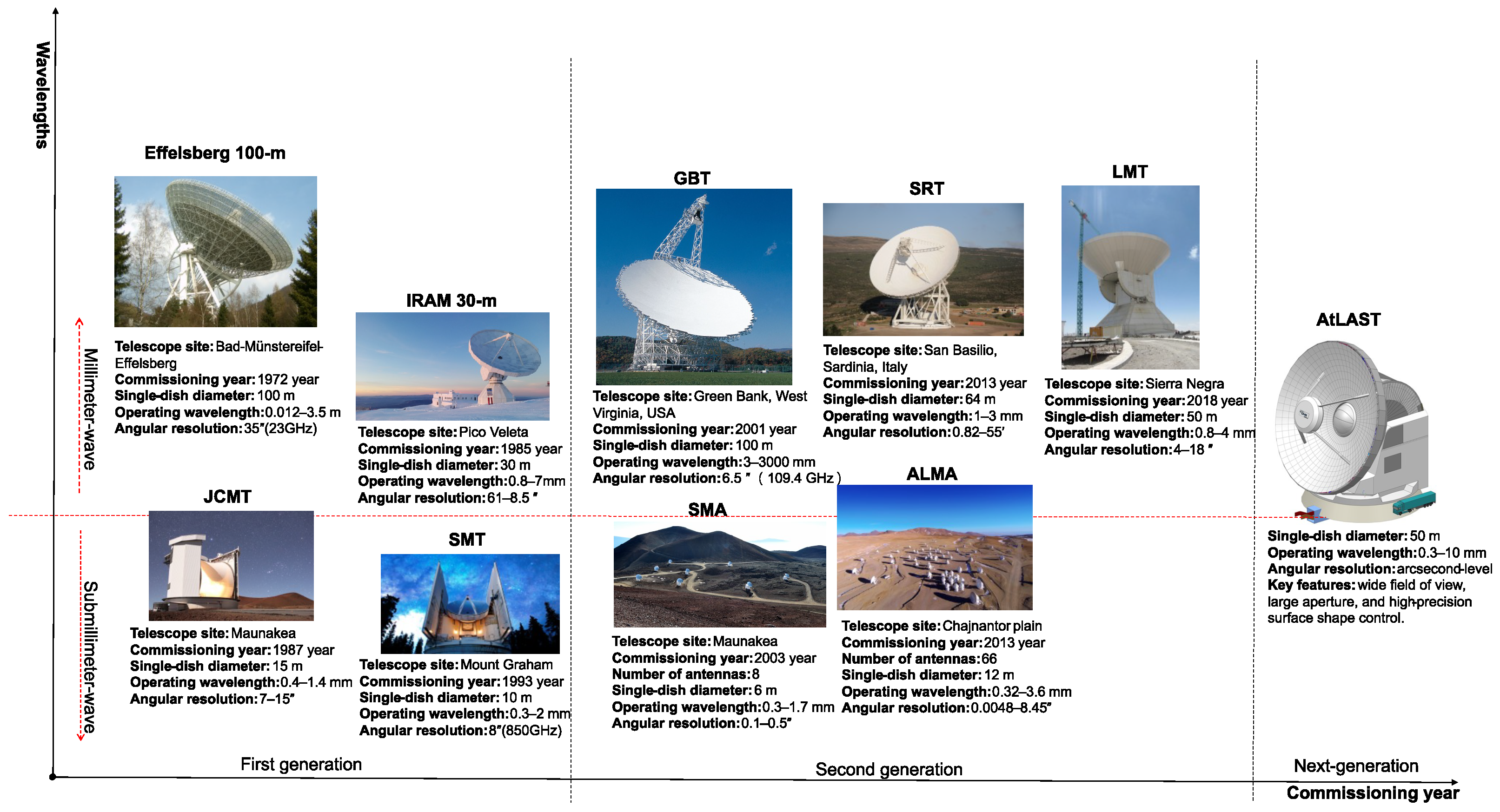
Figure 1. Development history of large-aperture radio telescopes. The figure illustrates the technological evolution of large-aperture radio telescopes along two dimensions: construction period and operating wavelength band. The horizontal axis represents the construction timeline, while the vertical axis distinguishes the primary operating windows of millimeter-wave (upper) and submillimeter-wave (lower) observations. The red dashed line and arrows schematically indicate the general arrangement of telescopes according to their typical operating wavelength ranges. Image credits: Effelsberg 100-m Telescope: Lapinov, via Wikimedia Commons, licensed under CC BY 4.0; IRAM 30-m Telescope: IRAM-gre, via Wikimedia Commons, licensed under CC BY-SA 4.0; Green Bank Telescope (GBT): NRAO/AUI/NSF, via Wikimedia Commons, licensed under CC BY 4.0; Sardinia Radio Telescope (SRT): caprowsky, via Wikimedia Commons, licensed under CC BY 3.0; Large Millimeter Telescope (LMT/GTM): Luyten, via Wikimedia Commons, licensed under CC BY-SA 3.0; James Clerk Maxwell Telescope (JCMT): Will Montgomerie/EAO/JCMT, via the Royal Astronomical Society, licensed under CC BY 4.0; Submillimeter Telescope (SMT): Used with permission from University of Arizona, David Harvey, photographer; distributed by ESO under CC BY 4.0; Submillimeter Array (SMA): Afshin Darian, via Wikimedia Commons, licensed under CC BY 2.0; Atacama Large Millimeter/submillimeter Array (ALMA): ALMA (ESO/NAOJ/NRAO), A. Marinkovic/X-Cam, via ESO, licensed under CC BY 4.0; Atacama Large Aperture Submillimeter Telescope (AtLAST): adapted from Figure 7 of Mroczkowski et al. [11], licensed under CC BY 4.0. All images were resized for layout purposes; no other modifications were made.
Galaxies 14 00079 g001
Figure 2. Architecture of the active surface shape control system. The diagram shows the relationships among external loads, the primary-reflector measurement subsystem, the structural-state monitoring module, the reflector surface control subsystem, and the actuator and segmented-reflector subsystem. The dashed box denotes the actuator and segmented-reflector subsystem, and the arrows indicate load application and the directions of monitoring feedback and control-signal flow.
Galaxies 14 00079 g002
Figure 3. Calibration stage of the active surface shape control system. The reflector surface is measured using techniques such as radio holography and photogrammetry, and the residual surface errors are obtained through surface reconstruction. Structural and environmental parameters, including temperature, stress, and wind load, are collected simultaneously. These data are used to update finite-element models or lookup tables, calculate actuator correction commands, and iteratively adjust the segmented panels through repeated measurement and correction.
Galaxies 14 00079 g003
Figure 4. Operational phase of the active surface shape control system. Operating and environmental parameters, including the elevation angle, temperature and wind load, are supplied to finite-element models or lookup tables to determine the target actuator displacements. The resulting commands drive the actuators to adjust the segmented reflector panels to the required surface configuration.
Galaxies 14 00079 g004
Figure 5. Schematic diagram of the theodolite-tape measurement method. The theodolite measures the viewing angle α of the target point P, while the steel tape measures the distance r from a reference point on the reflector axis to the target point P. The spatial coordinates of the target point are then calculated from the measured angle and distance. Z denotes the position coordinate of the optical theodolite.
Galaxies 14 00079 g005
Figure 6. Principle of a total station. The total station employs a spatial polar coordinate measurement method. By measuring the slope distance L, horizontal angle α , and elevation angle β of the target point P, the three-dimensional coordinates P ( x , y , z ) can be calculated.
Galaxies 14 00079 g006
Figure 7. Principle of a laser tracker. The laser tracker automatically tracks the target using returned-beam feedback and employs a spatial polar coordinate measurement method. By measuring the slope distance L, horizontal angle α , and elevation angle β of the target point P, the three-dimensional coordinates P ( x , y , z ) can be calculated.
Galaxies 14 00079 g007
Figure 8. Principle of a laser scanner. The laser scanner scans the reflector surface point by point using a laser beam. The slope distance and the corresponding horizontal and vertical angles of each scanned point are measured, and the three-dimensional coordinates of the points are calculated using a spatial polar coordinate method.
Galaxies 14 00079 g008
Figure 9. Photogrammetric Measurement Method. (a) Principle of triangulation; (b) Multi-view photogrammetric measurement process. Photogrammetric cameras acquire images of the reflector surface from different viewpoints, and corresponding feature points are matched among the images. After solving for the camera poses and photogrammetric baseline, the three-dimensional coordinates of the target points are determined based on the triangulation principle.
Galaxies 14 00079 g009
Figure 10. Holographic Measurement Method. The antenna under test scans around the direction of the satellite beacon source, while the reference antenna provides the phase reference. The holographic receiving system measures the amplitude and phase of the far-field beam. Based on the Fourier transform relationship between the far-field radiation pattern and the aperture field, the complex aperture field distribution is reconstructed, and the primary reflector surface errors are derived from the phase errors.
Galaxies 14 00079 g010
Figure 11. Surface Error to Actuator Command Mapping. (a) Mapping process from surface errors to actuator commands; (b) calibration stage of the active surface shape control system. The dashed lines indicate that (a) expands the closed-loop iterative process of “actuators and segmented reflector panels–holography, photogrammetry, etc.–finite-element models, lookup tables, etc.–actuators and segmented reflector panels.”
Galaxies 14 00079 g011
Figure 12. Close-up View of an Electromechanical Actuator. Close-up view of the electromechanical actuators at the edge of the GBT primary reflector. Image credit: NRAO/AUI/NSF; licensed under CC BY 4.0.
Galaxies 14 00079 g012
Table 1. Summary of surface measurement methods.
MeasurementRangeAccuracyMeasurement TimeRepresentative References
Theodolite-Based MeasurementTheodolite-tape method<30 m0.1–0.2 mm7–14 days[57]
Electronic theodolite<50 m0.01–0.2 mm3–8 h[58]
Laser measurementTotal station<200 m0.2–1.0 mm5–20 min[38]
Laser tracker<60 m10  μ m/m12–24 h[29]
Laser scanner<70 m<0.2 mm6 min–5 h[26,59]
Photogrammetry<200 m μ m + 4  μ m/m1–3 h[45,60]
Radio holographyPhase-referencedArbitrary0.05–0.5 mm30 min–8 h[18,61]
Phase-retrieval15 min–2 h[62,63]
Table 2. Major disturbance sources, measurement techniques, timescales, and mitigation strategies for large radio telescopes.
FactorMain EffectsTimescaleTypical Measurement
Techniques
Mitigation
Gravity Elevation-dependent reflector deformation, feed-arm flexure, and primary–subreflector misalignmentQuasi-static; s–min during slews and min–h during trackingPhotogrammetry; laser tracking and scanning; conventional radio holography or out-of-focus holographyElevation look-up tables or FEM feedforward; active-surface and subreflector correction
Wind Feed-arm/subreflector displacement, reflector deformation, and structural/servo vibrationSubsecond–seconds for dynamic response; seconds–minutes for gust-driven flexureAnemometry; accelerometry; optical quadrant-detector measurementsFEM or reduced-order feedforward; pointing/subreflector servo or active-surface correction
Thermal loads Thermoelastic surface deformation and drift in focus, alignment, and pointingMinutes–tens of minutes locally; tens of minutes–hours for global or diurnal variationsDistributed temperature sensing; laser scanning and ranging; out-of-focus holographyThermo-structural or empirical models; pointing/focus, subreflector, and active-surface correction; passive thermal control
Anomalous refraction Source wander, pointing jitter, and time-averaged beam broadeningMost events last less than 3–4 s; the distribution tail is approximately 10–20 s; occasional events last longerBeam-centroid tracking; phase-monitoring interferometryFrequent pointing calibration; real-time pointing correction (conceptual)
Notes: FEM, finite-element model; s, seconds; min, minutes; h, hours. The listed timescales are representative and depend on telescope size, structural dynamics, observing conditions, and measurement bandwidth.
Table 3. Comparison of actuator types, engineering characteristics, and typical applications.
Types of ActuatorsStrokePositioning AccuracyLoad CapacityResponse CharacteristicsTypical Applications
Electromechanicalmm–cm μ m100 N–kNModerateMainstream
Hydraulic>m0.1–1 mm>10 kNQuasi-staticCable-net shaping
Piezoelectric/voice-coil μ m–mmnm– μ mN–kNFast responseFine adjustment
Disclaimer/Publisher’s Note: The statements, opinions and data contained in all publications are solely those of the individual author(s) and contributor(s) and not of MDPI and/or the editor(s). MDPI and/or the editor(s) disclaim responsibility for any injury to people or property resulting from any ideas, methods, instructions or products referred to in the content.