1. Introduction
Advanced Virgo [
1] is a detector of gravitational waves (GW) consisting of a laser interferometer with orthogonal arms 3 km long and suspended mirrors. It is hosted by the European Gravitational Observatory near Pisa, in Italy. Its next upgrade, named Advanced Virgo Plus [
2], will be realised in two phases. The installation of Phase I will occur between the observation runs O3 and O4 and that of Phase II between O4 and O5. The main goal of Phase I is the reduction in the interferometer quantum noise, while Phase II will focus on the reduction in the mirror thermal noise. To do this, the beam on the end mirrors will be enlarged to a diameter of about 0.2 m, maintaining the same size on the input mirrors. Consequently, larger end mirrors will be installed for O5.
2. Description of the Problem
Scattered light, also known as stray light, is the light coming from the laser that does not follow the designed path in an optical system. One of the sources of scattered light is optical components with a limited aperture, which can lead to diffraction. The total losses in the mirrors in the current interferometers are very low. This means the amplitude of the scattered light is just of a few parts per million. This scattered light, however, may back-scatter and re-couple to the main cavity mode, introducing a shift in its phase. The phase modulation introduced by the coupled back-scattered light is due to the extra path this light has travelled and the possible vibration of optical elements it may have encountered along its path. In the current GW interferometers, the most usual scenario is light scattered by the main test masses that reflects in the walls of the vacuum pipe. The seismic motion of this pipe phase modulates the scattered light. If the stray light re-couples to the main cavity mode, the main laser beam will be polluted [
3].
To mitigate the effect of stray light, many different solutions can be taken. One of them is controlling the displacement of potential scatterers. Moreover, the coupling factor or the amount of recombining scattered light can be minimised. Another solution is resorting to baffles and diaphragms, which obscure roughness and discontinuities from the line of sight of the core optics. They are designed in such a way that they can intercept and absorb as much stray light as possible [
4,
5]. For these reasons, their reflectivity must be very low. Moreover, to avoid the baffles from being affected by seismic motion that could be transmitted to the scattered light, some of them are suspended.
In Advanced Virgo, a baffle is placed in front of the cryotrap (large cryotraps at the end of the 3 km pipes were installed in Advanced Virgo to lower the residual pressure by a factor of about 100 with respect to the Virgo interferometer) close to the end mirror (EM) to avoid stray light coming from the input mirror (IM). In addition to this baffle, referred to as cryobaffle hereinafter, there are vacuum bellows and a gate valve, but the aperture of these components is larger than that of the cryobaffle. Therefore, the aperture of the cryobaffle could clip (or cut out) the beam that would reach the external part of the EM in O5, and it might be necessary to enlarge the cryobaffle (see Section 5.3.4.2.1 from Ref. [
6]). However, this is a high-risk operation that would require displacing the cryotrap and the end tower.
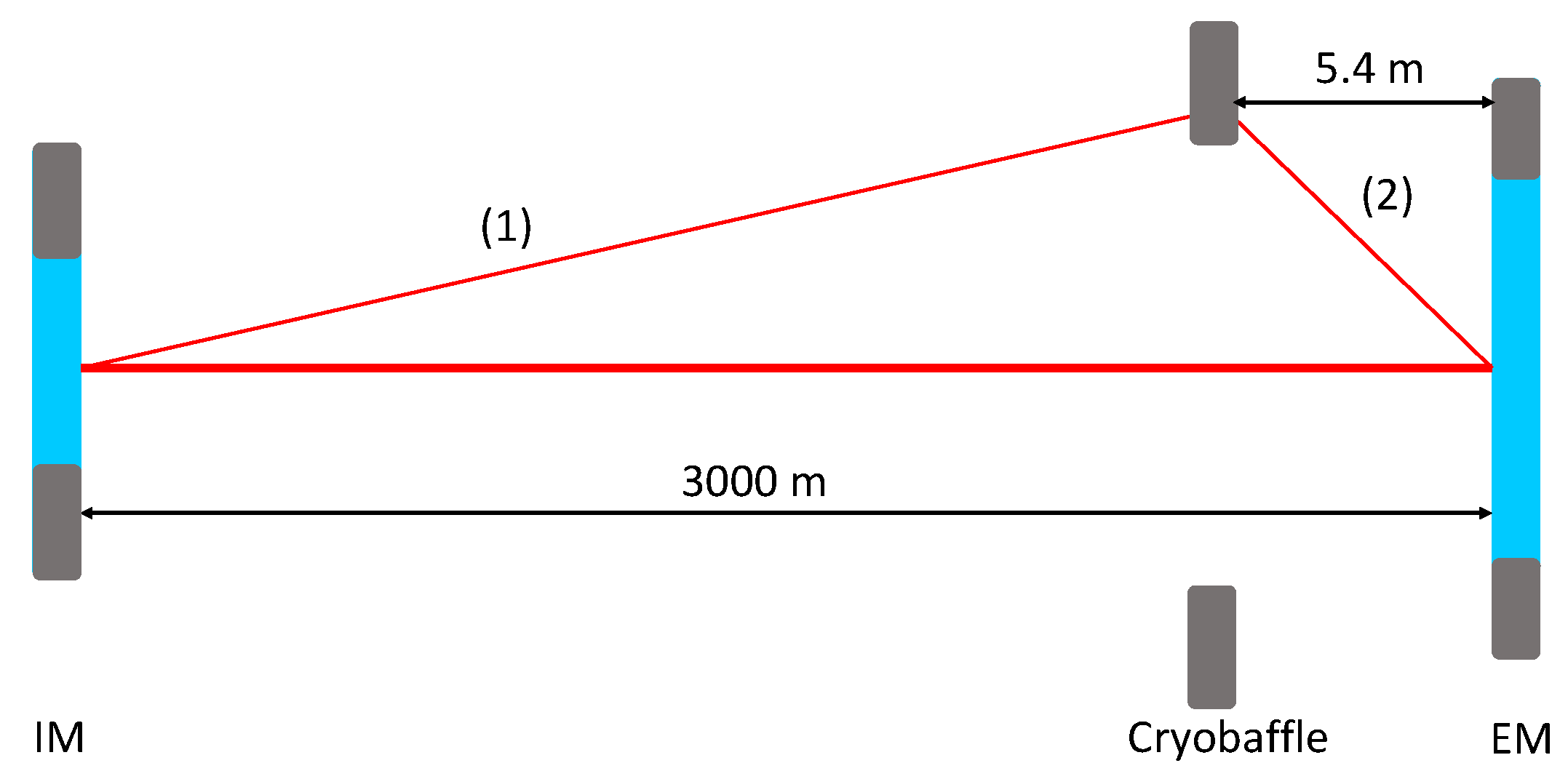
The cryobaffle is located at 5.4 m from the EM. The diameter of the IM will be 0.35 m and that of the EM 0.55 m, with coating only in apertures of 0.34 m and 0.53 m, respectively [
2]. The inner diameter of the baffle shielding the IM (EM) is 0.33 m (0.52 m), which is the value considered as an effective aperture of the IM (EM). The cryobaffle has an aperture of 0.6 m and an outer diameter of 0.94 m. The light scattered by the IM (EM) in the direction of the cryobaffle, shown as path 1 (2) in
Figure 1, corresponds to a small (large) scattering angle. As mentioned above, this light will acquire an extra phase corresponding to the displacement of the cryobaffle. Part of this light may scatter back into the solid angle in the direction of the IM (EM) and eventually recombine to the main propagating mode.
3. Methodology
The ultimate objective from this paper is projecting the noise generated by the back-scattered light from the cryobaffle over the O5 sensitivity curve. In order to discard this stray light as a risk, the projection should be about a factor of ten below the sensitivity curve. The noise projection is conducted resorting to [
7]
where
is the coupling constant, i.e., the probability for the back-scattered light coming from the cryobaffle to recouple to the main resonating cavity mode;
is the effective displacement of the back-scatterer, the cryobaffle in our case; and the ratio
is the ratio of transfer functions (TF) between the power reaching the asymmetric port of the interferometer, or dark fringe (df), and the length difference of the arm cavities degree-of-freedom (DARM) or the baffle displacement
. The effective displacement is given by the power spectral density (PSD) of the sinus of the real displacement
where
is the real displacement in time domain, and
is the light wavelength, 1064 nm.
4. Computation of the Coupling Constant
The probability for the light from either of the paths shown in
Figure 1 to re-couple to the main mode is commonly known as the coupling constant and is mathematically expressed as the square root of the scattered light power that has recombined to the main cavity mode
, divided by the circulating power in the arm
, as shown in Refs. [
8,
9]
where
is the probability for a mirror to scatter photons from the main beam in the direction of the solid angle
from the mirror to the cryobaffle. The solid angle from the cryobaffle to the mirror is implicitly included by the reciprocity relation in
. Finally,
is the probability for photons reaching the back-scatterer (in our case the cryobaffle) to back-scatter into a unit solid angle in the direction of the mirror, where
r is the distance between the cryobaffle and the mirror.
As we will see below, the coupling constant for a large scattering angle is comparable to that for a small scattering angle, so both contributions will be included in the projection.
4.1. Small Scattering Angle
According to Equation (
3), we need to compute the solid angle in the direction of the cryobaffle from the IM. Following
Figure 2, the value of the solid angle is
str.
We use a fast-Fourier-transform (FFT) simulation tool (see
Section 4.1.1) to compute
, obtaining a value of 1.91 ppm. Given the solid angle of
str,
is
. The probability of light back-scattering into the solid angle in the direction of IM,
, is the bidirectional reflectance distribution function (BRDF) of the surface of the cryobaffle. The BRDF was firstly derived in Ref. [
10] and is defined as the scattered surface radiance divided by the incident surface irradiance. The surface irradiance is the light flux incident on the surface per unit illuminated surface area. The scattered surface radiance is the light flux scattered through a solid angle
per unit illuminated surface area per unit projected solid angle [
11]. The projected solid angle is obtained by multiplying the solid angle
by
, where
is the angle between the incoming light direction and the surface normal. Therefore,
The value of this BRDF is obtained from actual measurements and is of the order of
str. Finally, using Equation (
3), the coupling constant for small scattering angles is
4.1.1. Stationary Interferometer Simulation and the Implementation of the Cryobaffle
The “Stationary Interferometer Simulation” (SIS) is an FFT-based simulation package that calculates fields in a stationary interferometer under different configurations. SIS calculates fields in optical systems by taking into account realistic details of optical components, such as macroscopic shapes and microscopic surface phasemaps. SIS also serves as an analysis tool of optical system characteristics. For instance, after stationary-state fields are calculated, a mode analysis can be run to obtain the mode matching (see Refs. [
12,
13] for further information).
In order to simulate the cryobaffle, a ring with an inner aperture of 0.6 m has been placed at 5.4 m from the EM. This structure shields the field outside of this clear aperture and sets up a resonator with a clipper at this location, i.e., the resonating field is chopped off at 0.6 m of aperture at this location. The amount of the field reflected by this ring into the main resonating field is calculated as discussed above.
The amount of power that recouples to the main resonating field, , needs to be estimated so that it can be compared to the GW signal, , where a and are very small quantities (). On the other hand, the loss of power in the arm cavity due to the scattering by the cryobaffle is much smaller than other major losses, and it is therefore not necessary to include it in the calculation of the arm cavity power: , .
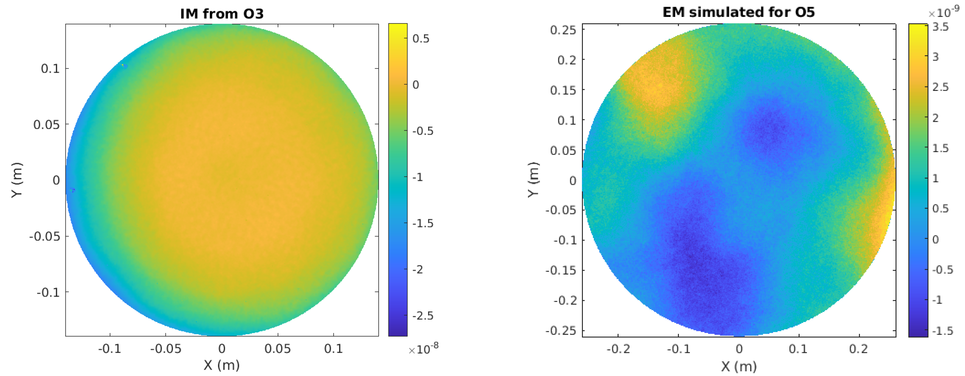
One of the SIS advantages is the possibility to include realistic surface maps. The ones used in this simulation are shown in
Figure 3. The IM map used in this simulation was measured in Virgo during O3, obtaining a roughness of the order of nanometers, whereas a simulated map has been used for the larger O5 EM. Their PSD can be seen in
Figure 4. The bump seen at 0.1/mm in the PSD of the IM map can lead to scattering reaching the baffles of the walls of the tube.
4.2. Large Scattering Angle
In this case, we focus on path (2) from
Figure 1. The Virgo surface maps do not have enough resolution to be used in SIS, so we compute the total energy hitting the cryobaffle facing the EM analytically. The resolution of the mirror maps is 0.4 mm. From this resolution, the maximum angle a simulation in which this mirror map is used can only cover angles up to
, where
is, as mentioned above, the laser wavelength. However, the simulation cannot fully use the resolution of the data due to technical limitations, and the practical limit of the resolution is 1 mm, which corresponds to
. Hence, this is why we cannot use simulations for the estimation of the coupling for scattering at large angles. This quantity is then computed with the BRDF of the EM and the solid angle from the EM in the direction of the cryobaffle. Following
Figure 5, the value of the solid angle is
str.
Then, the BRDF of the mirror can be retrieved from
Figure 6 (mirrors from LIGO and Virgo were polished by ZYGO [
15]. Moreover, the coatings are the same, done at LMA [
16]. For that reason, it is expected that Virgo and LIGO mirrors have a similar performance). For scattering angles of about 3 degrees (angle
rad in
Figure 5), the BRDF is of around
. With these results,
ppm.
With the solid angle of
str and the total power reaching the cryobaffle 1 ppm,
. Finally, the BRDF of the side of the cryobaffle in consideration is still
. Using Equation (
3), the coupling constant for large scattering angles is
4.3. Calculation of the Small Scattering Angle Coupling Constant Using the Geometrical Model
In
Section 4.1, we have computed the probability of the IM to scatter photons in the direction of the cryobaffle using SIS. As a cross-check, we compute that probability using the geometrical model presented in the previous section instead. We have seen that
str, and in the LIGO BRDF plot, a value of
corresponds to an angle of
degrees (
rad) so that
ppm, close to the 1.91 ppm value we have obtained from simulation.
5. Cryobaffle Displacement
Two different approaches are taken in order to determine the displacement of the cryobaffle. On the one hand, we consider the global motion of the cryobaffle together with the structure to which it is fixed, using data from accelerometers and velocimeters placed in the vicinity of the cryobaffle. On the other hand, we consider the cryobaffle inner mode resonances, using data obtained in noise injections performed in the cryotrap.
5.1. Accelerometer Plus Velocimeter Data
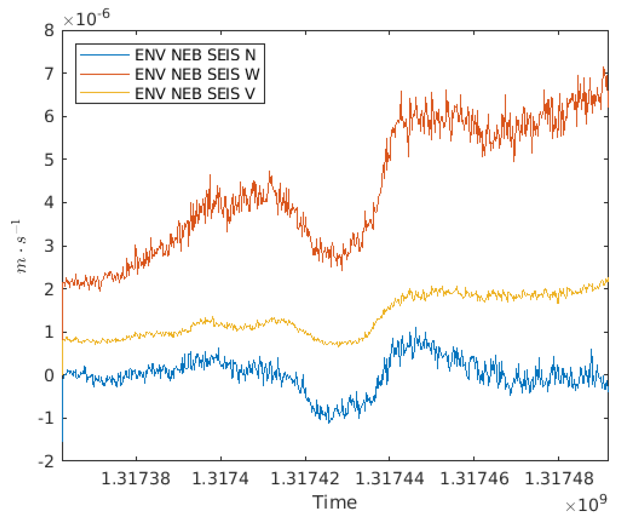
To consider the worst case scenario, we select a time period with high micro-seismic noise due to bad weather, as shown in
Figure 7. After the GPS time 1,317,448,818, which corresponds to 5 October 2021, the micro-seismic motion is
m/s.
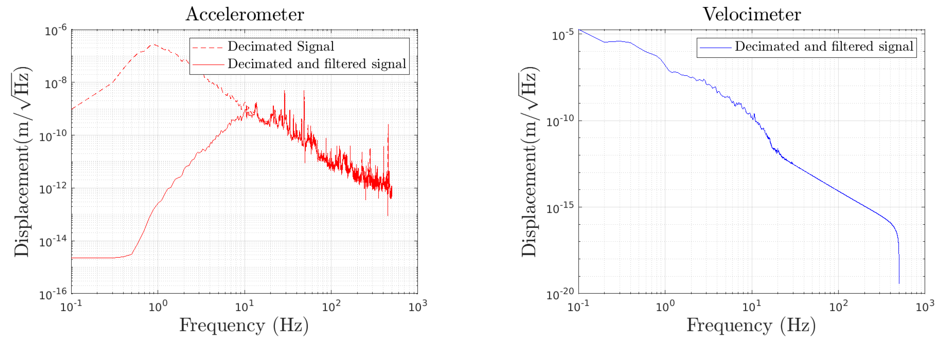
The accelerometer data are double-integrated so as to obtain the corresponding displacement. They are then high-pass filtered with a cutoff frequency of 10 Hz. We also notch the 50 Hz line, as well as its harmonics, due to the power mains. The displacement from the accelerometer data after being pre-processed is seen in
Figure 8 (left), red solid curve. Because accelerometers are not accurate at frequencies below 10 Hz, we use the data from a velocimeter for the low-frequency region. The velocimeter data are integrated to obtain the corresponding displacement. They are, first, high-pass filtered with a cutoff frequency of 0.2 Hz to remove noise at very low frequencies. They are then low-pass filtered with a cutoff frequency of 10 Hz. The displacement from the velocimeter after pre-processing is shown in
Figure 8 (right).
The motion of the cryobaffle
is obtained in terms of the ground motion
multiplied by the TF from the ground motion to the tube and the TF from the tube to the cryobaffle. Mathematically, it can be expressed as
. The accelerometer measures
, which means that
needs to be computed or measured. In our case, it is retrieved from a measurement campaign from 2015 [
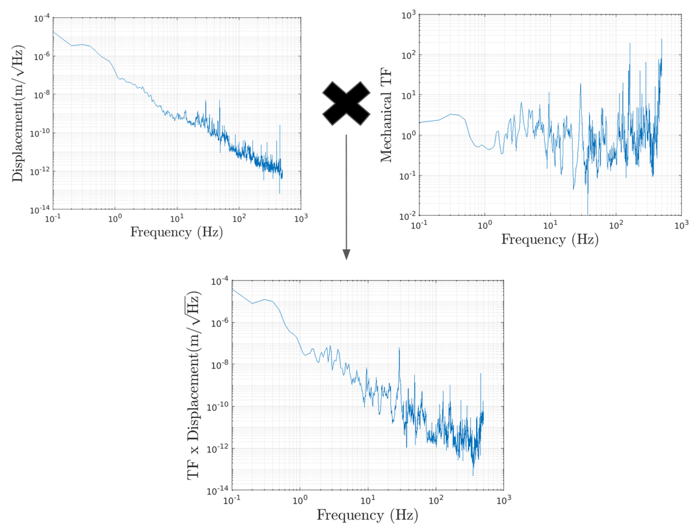
18]. Finally, the displacement, obtained by combining the accelerometer and velocimeter data, is multiplied by the mechanical TF from the tube to the cryobaffle, as shown in
Figure 9.
We then need to apply the fringe wrapping formula (Equation (
2)) over the curve at the bottom of
Figure 9 to obtain the effective displacement. For this purpose, the displacement needs to be in time domain. Because we have it in frequency domain, we obtain the displacement in time domain
as a sum over frequencies of the displacement in frequency domain
weighted by the sinus of the frequency
where
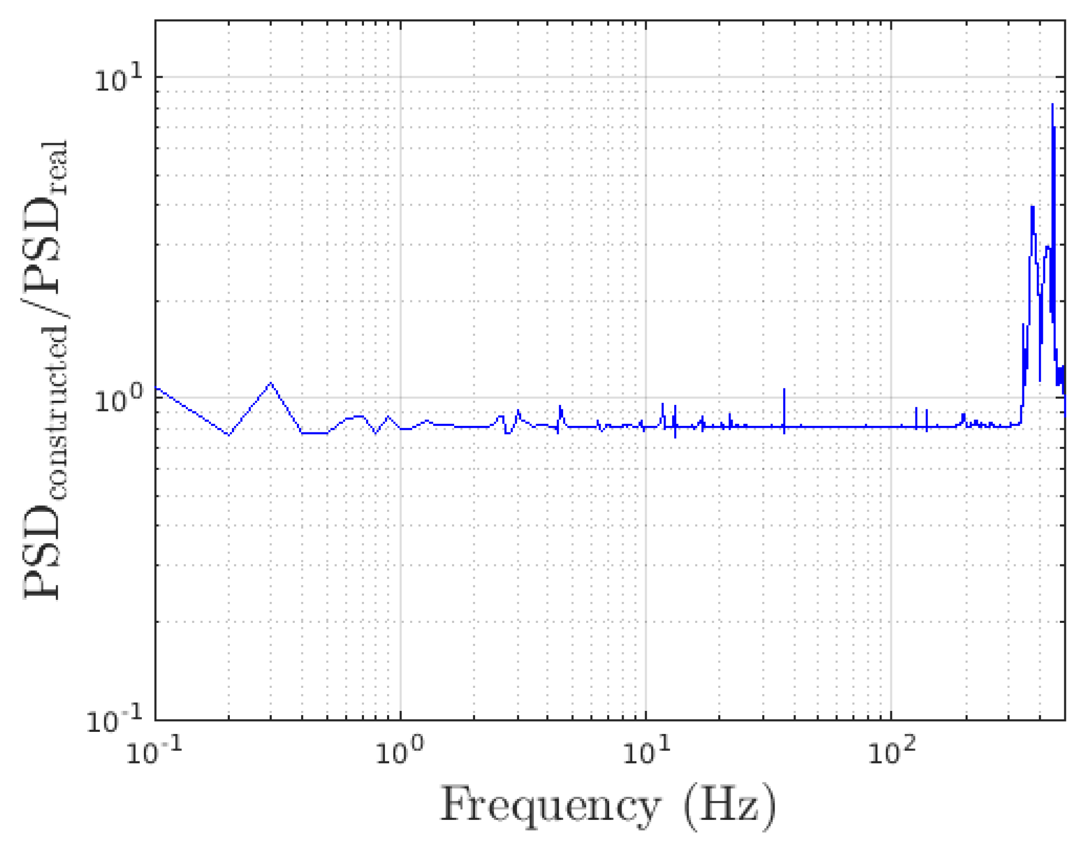
is a phase, set to 0. To check the validity of this method, the PSD of this displacement (in time domain) is computed and then compared with the original PSD (in frequency domain). This comparison is presented in the form of a ratio in
Figure 10, where a good agreement is observed.
Finally, we apply the fringe wrapping formula to obtain the effective displacement, as shown in
Figure 11. The dashed red curve shows the usual “shoulder”, characteristic of scattered light, at around 80 Hz.
5.2. Displacement from Mechanical Characterisation of the Cryobaffle
A campaign of onsite measurements was performed in 2015 in order to mechanically characterise some baffles. For characterising the cryobaffles, the procedure in Section 2.3 from Ref. [
18] was followed. The seismic displacement of the cryotrap was evaluated with a statistical approach. Data were collected by three accelerometers for weeks. From these data–percentile curves (an n-percentile curve implies that for the n% of the times, the real noise is below this level) were computed. We retrieve the curve at 50% from Figure 22 of that reference.
These data are in the frequency domain, so we need to determine the displacement in the time domain so as to be able to apply the fringe wrapping formula. For this purpose, we expand the displacement, following the same procedure described in the previous section. Again, to test the validity of the method, the PSD of this displacement is computed and then compared with the original PSD from
Figure 12. This comparison is presented in the form of a ratio in
Figure 13, where a good agreement is observed. Hence, the fringe wrapping formula (Equation (
2)) can be applied.
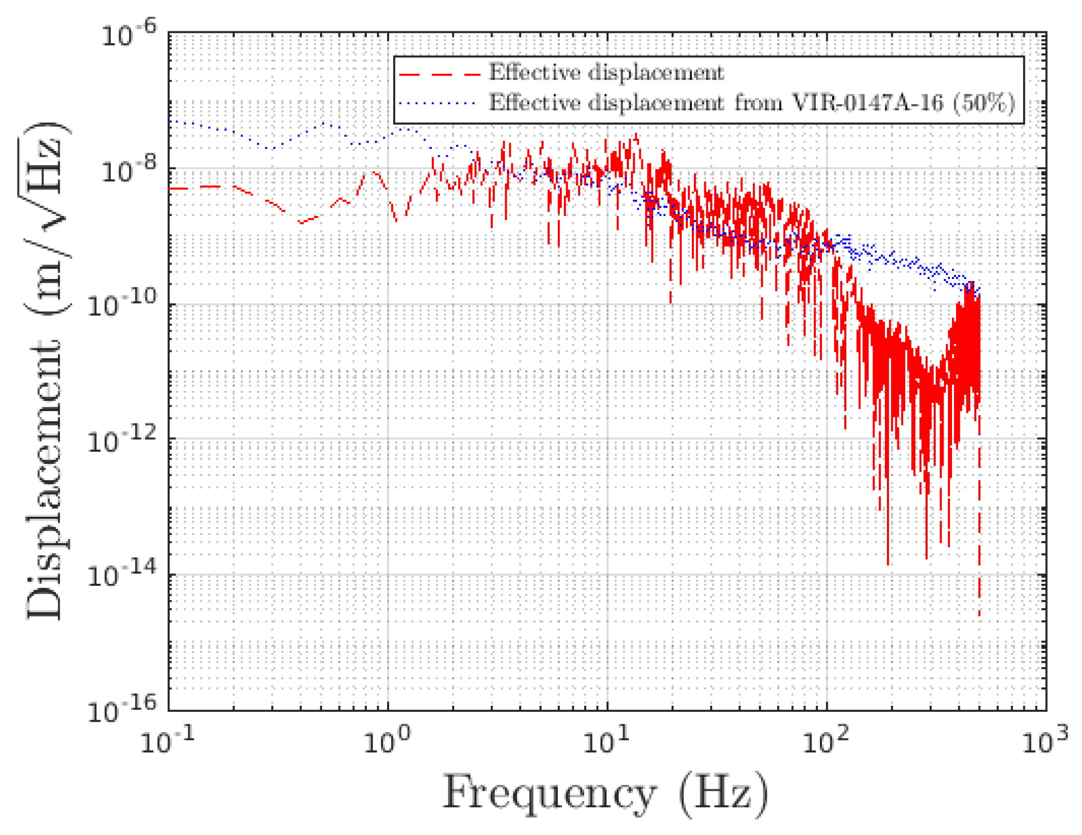
Figure 14 shows a comparison of the effective displacement and the original displacements.
Finally,
Figure 15 shows a comparison of the effective displacement obtained in this section with the one obtained in the previous one. For frequencies below 100 Hz, there is a good agreement between the two displacements.
6. Transfer Function from the Cryobaffle to the Strain
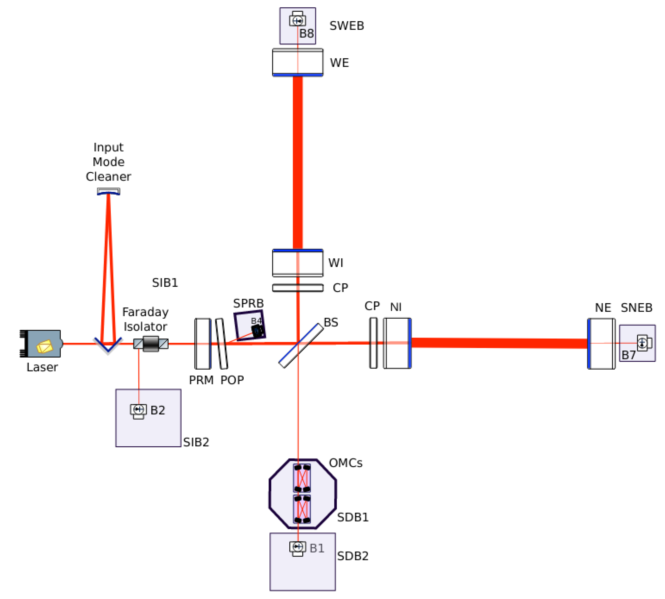
In the transmission from the end mirrors, there are suspended detection benches, as can be seen in
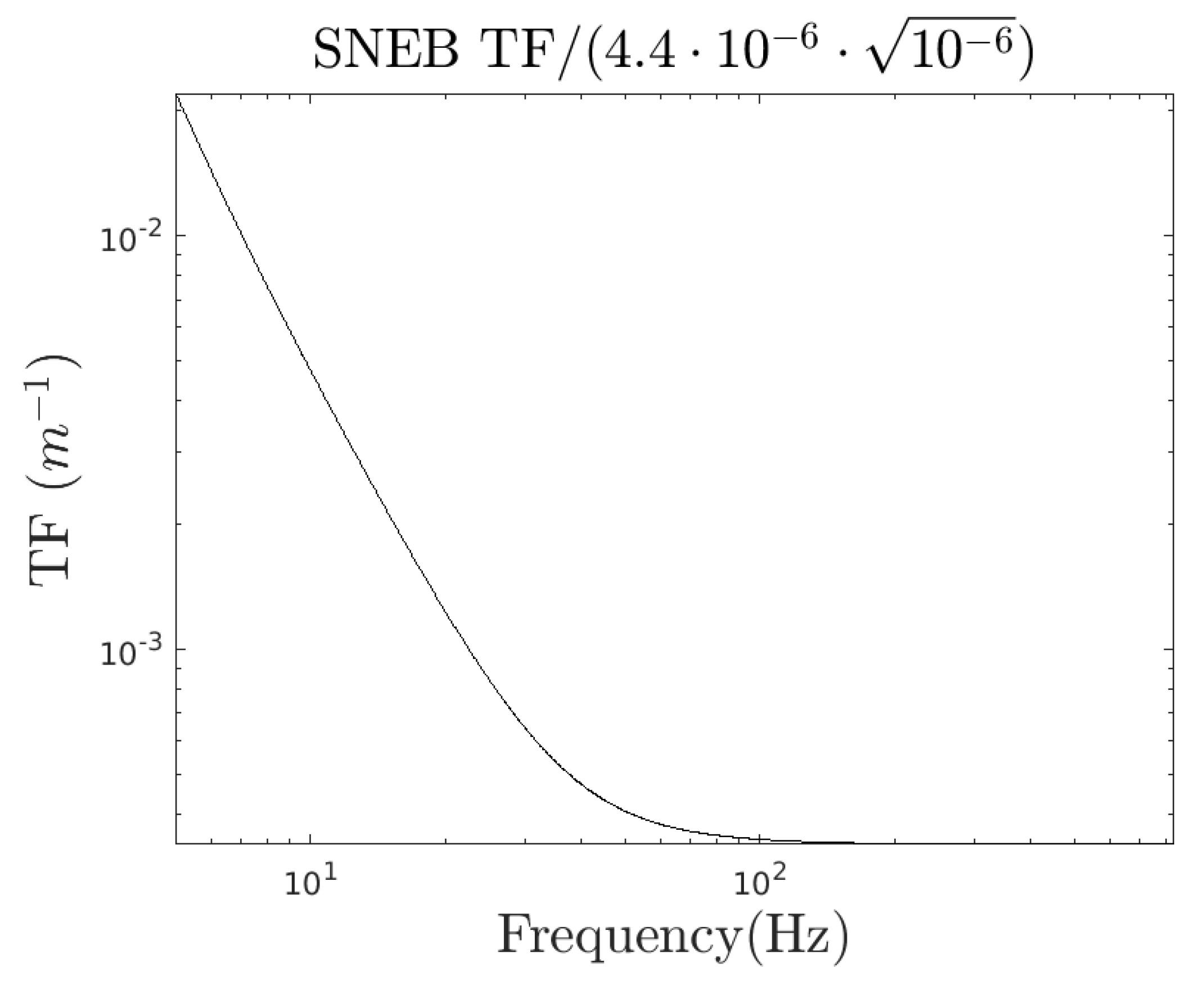
Figure 16. The TF from the detection benches to the DARM was derived by determining the TF from the end bench to the dark fringe and that from the DARM to the dark fringe. The ratio of the two TFs divided by the arm length gives the coupling from the end bench motion to the strain. In the simulation, the bench was replaced by an optic whose reflectivity was 1 ppm, which sent a 1 ppm ghost beam perfectly matched with the cavity arm back towards the EM, and the rest of the light was absorbed. The 1 ppm back-reflection value was chosen to be sufficiently small so as not to change the working point of the interferometer in the simulation but sufficiently large to avoid numerical approximation errors.
We use the results of the simulation, divided by a suppression factor to account for the fact that the light must cross the mirror to reach the detection bench, to derive the TF from the cryobaffle to the strain. Indeed, light scattered by the suspended detection benches is reduced twice by the transmission of the EM, which is approximately 4.4 ppm, as the light goes into the bench and then out of it back into the cavity. Therefore, the final TF for the cryobaffle is
. This TF, shown in
Figure 17, includes the
factor in Equation (
1) [
20].
7. Noise Projection
The final step consists of evaluating Equation (
1) with all the factors that have been computed in the previous sections. Given that the noise coming from the two arms is incoherent, we add them in quadrature. Consequently, and under the assumption that both the displacement of the cryobaffles and the TFs are the same in both arms, the final projection is:
where
, assuming the small and large angle noises are coherent with a relative phase 0.
The final result is presented in
Figure 18. The black solid curve is the best expected sensitivity curve for O5, and the noise projection has to be compared with this curve, divided by a factor of ten as a safety margin (black dashed curve). In dashed red, the projection of the cryobaffle displacement obtained in
Section 5.1 can be seen. In solid blue is the projection of the cryobaffle displacement from
Section 5.2. Because the latter corresponds to the 50% percentile curve, we repeated the above procedure using the 99% percentile curve, also from Ref. [
18], and obtained the dotted black curve. This curve represents the most conservative projection and still remains below the factor-of-ten safety margin, so it can be claimed that the light back-scattered by the cryobaffle that can recombine to the main cavity mode will not be detrimental to the overall sensitivity in O5.
We have also computed the amount of light that would be clipped by a cryobaffle with a larger aperture and the difference is negligible with respect to the current cryobaffle.
8. Conclusions
The enlargement of the end mirrors in the Virgo interferometer before its fifth observing run will modify the width of the beam propagating in the main arms. Hence, the cryobaffle may clip part of the beam, which will be phase modulated due to the displacement of the cryobaffle. This phase-modulated scattered light may back-scatter to the test masses and eventually recouple to the main cavity mode. In this paper, we have computed the probability of this back-scattered light to recouple to the main cavity mode and assessed whether this could affect the overall interferometer sensitivity. Our work shows that the noise projection lies below the factor ten safety margin, below the sensitivity curve. This implies the sensitivity may not be affected by the back-scattered light recoupled to the main cavity mode.
Nevertheless, several hypotheses have been used to derive the final noise projection, in particular, the assumption that the displacement, BRDF, TFs, etc., of the cryobaffle, as well as the properties of the mirrors, are identical in both arms. To compute the coupling constant, we have used old measurements of the baffles and mirrors properties. Furthermore, in the absence of the BRDF measurements of the Virgo mirrors at large angles, we have used the corresponding LIGO values, given that all the mirrors were polished and coated by the same companies. In the near future, the measurements of the BRDF of the new Virgo mirrors will have to be taken in a range of scattering angles as wide as possible and the properties of the existing cryobaffles cross-checked. Finally, the results may change due to potential point absorbers in the IM and EM coatings. Point absorbers cause localised thermal deformations of the mirrors that may scatter more light and thus lead to an increased amount of re-coupled back-scattered light.
Author Contributions
Conceptualization, H.Y.; Formal analysis, A.R.-R. and H.Y.; Funding acquisition, M.M.; Investigation, A.R.-R., L.M.M. and H.Y.; Methodology, A.R.-R., L.M.M. and H.Y.; Supervision, M.M. and L.M.M.; Validation, H.Y., M.M. and L.M.M.; Writing—original draft, A.R.-R. and L.M.M.; Writing—review and editing, H.Y. All authors have read and agreed to the published version of the manuscript.
Funding
This work is partially supported by the Spanish MCIN/AEI/10.13039/501100011033 under the grants SEV-2016-0588, PGC2018-101858-B-I00, and PID2020-113701GB-I00, some of which include ERDF funds from the European Union. IFAE is partially funded by the CERCA program of the Generalitat de Catalunya. Part of this material is based upon work supported by LIGO Laboratory, a major facility operated by Caltech and MIT for the U.S. National Science Foundation and funded under Cooperative Agreement No. PHY-1764464.
Institutional Review Board Statement
Not applicable.
Informed Consent Statement
Not applicable.
Data Availability Statement
Not applicable.
Acknowledgments
We would like to thank Michal Was and Jerome Degallaix for their continuous feedback and help. We also wanted to thank Irene Fiori, Antonino Chiummo, Antonio Pasqualetti and Maddalena Mantovani for their very useful contributions. Finally, we want to thank Eleonora Polini for providing the GPS times at which there were high micro-seisms and to Manuel Pinto for his help with the mechanical TF of the cryobaffle.
Conflicts of Interest
The authors declare no conflict of interest.
References
- Acernese, F.A.; Agathos, M.; Agatsuma, K.; Aisa, D.; Allemandou, N.; Allocca, A.; Amarni, J.; Astone, P.; Balestri, G.; Ballardin, G.; et al. Advanced Virgo: A second-generation interferometric gravitational wave detector. Class. Quantum Grav. 2015, 32, 024001. [Google Scholar] [CrossRef]
- Flaminio, R. Status and plans of the Virgo gravitational wave detector. In Proceedings of the International Society for Optics and Photonics, Online, 14–18 December 2020. [Google Scholar] [CrossRef]
- Thorne, K. Light Scattering and Proposed Baffle Configuration for the LIGO, LIGO-T890017-x0. 2021. Available online: https://dcc.ligo.org/DocDB/0028/T890017/000/T890017-00.pdf (accessed on 20 May 2022).
- Romero-Rodríguez, A.; Allocca, A.; Chiummo, A.; Martínez, M.; Mir, L.M.; Yamamoto, H. Determination of the light exposure on the photodiodes of a new instrumented baffle for the Virgo input mode cleaner end-mirror. Class. Quantum Grav. 2021, 38, 045002. [Google Scholar] [CrossRef]
- Ballester, O.; Blanch, O.; Cardiel, L.; Cavalli-Sforza, M.; Chiummo, A.; García, C.; Illa, J.M.; Karathanasis, C.; Kolstein, M.; Martínez, M.; et al. Measurement of the stray light in the Advanced Virgo input mode cleaner cavity using an instrumented baffle. Class. Quantum Grav. 2022, 39, 115011. [Google Scholar] [CrossRef]
- The Virgo Collaboration. Advanced Virgo Plus Phase I Design Report; Technical Report VIR-0596A-19; Virgo TDS: Pisa, Italy, 2019. [Google Scholar]
- Chiummo, A.; Marque, J. AdV—Stray Light Control: Calculation of Displacement Noise Induced by the Cryotrap Baffle; Technical Report VIR-0272A-12; Virgo TDS: Pisa, Italy, 2012. [Google Scholar]
- Flanagan, E.; Thorne, K.S. Noise Due to Backscatter Off Baffles, the Nearby Wall, and Objects at the Far end of the Beam Tube and Recommended Actions; Technical Report LIGO-T940063-00-R; LIGO: Hanford Site, WA, USA, 1994. [Google Scholar]
- Fritschel, P.; Yamamoto, H. Scattered Light Noise Due to the ETM Coating Ripple; Technical Report LIGO-T1300354-v3; LIGO: Hanford Site, WA, USA, 2013. [Google Scholar]
- Nicodemus, F.E.; Richmond, J.C.; Hsia, J.J.; Ginsberg, I.W.; Limperis, T. Geometrical Considerations and Nomenclature for Reflectance; Jones and Bartlett Publishers, Inc.: Burlington, MA, USA, 1992. [Google Scholar]
- Stover, J.C. Optical Scattering: Measurement and Analysis; SPIE Optical Engineering Press: Bellingham, WA, USA, 1995; ISBN 9780819478443. [Google Scholar]
- Yamamoto, H.; Barton, M.; Bhawal, B.; Evans, M.; Yoshida, S. Simulation tools for future interferometers. J. Phys. Conf. Ser. 2006, 32, 398. [Google Scholar] [CrossRef]
- Yamamoto, H. SIS (Stationary Interferometer Simulation) Manual; Technical Report LIGO-T070039-v8; LIGO: Hanford Site, WA, USA, 2013; Available online: https://dcc.ligo.org/LIGO-T070039-v8/public (accessed on 1 June 2022).
- Degallaix, J.; Michel, C.; Sassolas, B.; Allocca, A.; Cagnoli, G.; Balzarini, L.; Dolique, V.; Flaminio, R.; Forest, D.; Granata, M.; et al. Large and extremely low loss: The unique challenges of gravitational wave mirrors. J. Opt. Soc. Am. A 2019, 36, C85–C94. [Google Scholar] [CrossRef]
- ZYGO Metrology Systems. Available online: https://www.zygo.com (accessed on 28 May 2022).
- Laboratoire de Mécanique et d’Acoustique. Available online: http://www.lma.cnrs-mrs.fr (accessed on 30 May 2022).
- LIGO collaboration. LIGO Optics. Available online: https://galaxy.ligo.caltech.edu/optics/ (accessed on 30 May 2022).
- Nicodemus, F.E.; Richmond, J.C.; Hsia, J.J. Baffle Internal Modes In-Situ Measurement and Noise Projection; Technical Report VIR-0147A-16; Virgo TDS: Pisa, Italy, 2012. [Google Scholar]
- Acernese, F.; Adams, T.; Agatsuma, K.; Aiello, L.; Allocca, A.; Amato, A.; Antier, S.; Arnaud, N.; Ascenzi, S.; Astone, P. Status of Advanced Virgo. EPJ Web Conf. 2018, 182, 02003. [Google Scholar] [CrossRef][Green Version]
- Wąs, M.; Gouaty, R.; Bonnand, R. End benches scattered light modeling and subtraction in Advanced Virgo. Class. Quantum Grav. 2018, 38, 075020. [Google Scholar] [CrossRef]
Figure 1.
Position of the cryobaffle in one of the main arms. Mirrors are represented in blue and baffles in grey. Scattered light from IM (EM) could back-scatter, following path (1) (path (2)), and recombine to the main beam resonating in the cavity.
Figure 1.
Position of the cryobaffle in one of the main arms. Mirrors are represented in blue and baffles in grey. Scattered light from IM (EM) could back-scatter, following path (1) (path (2)), and recombine to the main beam resonating in the cavity.
Figure 2.
Solid angle into the direction of the IM. The cryobaffle is placed at about m from the IM. The value of the solid angle is str.
Figure 2.
Solid angle into the direction of the IM. The cryobaffle is placed at about m from the IM. The value of the solid angle is str.
Figure 3.
(
Left) IM surface-map obtained from measurements of the IM surface at Virgo in O3, obtaining a roughness of the order of nanometers. We decided to use the map measured up to 0.29 m in diameter. However, the extrapolation to the mirror edge is negligible, so we do not show it in this plot. A detailed description on the measurements leading to these surface maps can be found in Ref. [
14]. (
Right) EM-simulated surface-map. Notice the larger aperture of EM (0.52 m). For the large O5 mirrors, no real data are available as the substrates are currently in the polishing phase. Thus, for the simulation, we rely on simulated surface maps having the same spatial characteristics as the current mirrors as the polishing specifications are identical for the O3 and O5 mirrors (albeit for O5, the specifications are defined on a larger diameter).
Figure 4.
PSDs of the used surface maps. The PSD of the IM’s map has a bump at a spatial frequency of 0.1/mm. This can lead to scattering reaching the baffles in the walls of the tube.
Figure 4.
PSDs of the used surface maps. The PSD of the IM’s map has a bump at a spatial frequency of 0.1/mm. This can lead to scattering reaching the baffles in the walls of the tube.
Figure 5.
Solid angle from the EM in the direction of the cryobaffle. The distance between the EM and the cryobaffle is 5.4 m. The value of the solid angle is str.
Figure 5.
Solid angle from the EM in the direction of the cryobaffle. The distance between the EM and the cryobaffle is 5.4 m. The value of the solid angle is str.
Figure 6.
BRDF of the main test masses. The BRDF for scattering angles between
and
degrees can be obtained from the real surface maps of the mirrors. Information on the Virgo and LIGO surface maps is provided in Refs. [
14] and [
17], respectively. The values corresponding to scattering angles of about
degrees are obtained from measurements conducted by baffle photodiodes in LIGO. The BRDF at scattering angles around 10 degrees is obtained by measurements with integrating spheres, viewports, etc. The pink and blue dashed lines (labelled as “Laurent IM02” and “Laurent IM04”, respectively) were measured with a small laser beam with low power,
W, and sample spot diameter of 2 mm.
Figure 7.
Micro-seismic motion detected by the velocimeters closest to the cryotrap. The three curves correspond to the movements in the different directions: the red curve corresponds to the west direction, the yellow one to the vertical direction and the blue one to the north direction. High seismic activity in the west direction is observed after time 1,317,448,818.
Figure 8.
The displacement of the cryobaffle is obtained by merging data from an accelerometer for frequencies above 10 Hz (left ) with data from a velocimeter for frequencies below 10 Hz (right).
Figure 8.
The displacement of the cryobaffle is obtained by merging data from an accelerometer for frequencies above 10 Hz (left ) with data from a velocimeter for frequencies below 10 Hz (right).
Figure 9.
(
Top left corner) Combination of the accelerometer and velocimeter data presented in
Figure 8. (
Top right corner) Mechanical TF from the tube to the cryobaffle. (
Bottom) Final cryobaffle displacement, obtained by multiplying the accelerometer plus velocimeter data by the cryobaffle mechanical TF.
Figure 10.
Ratio of the PSD from the expansion and the real PSD from accelerometer and velocimeter combined data. The ratio shows values that fluctuate around 1, implying the validity of the method.
Figure 10.
Ratio of the PSD from the expansion and the real PSD from accelerometer and velocimeter combined data. The ratio shows values that fluctuate around 1, implying the validity of the method.
Figure 11.
The black solid curve is the displacement of the cryobaffle, obtained from merging the data from an accelerometer and a velocimeter and then multiplying by the mechanical TF. The dashed red curve is the effective displacement, result of applying the fringe wrapping over the blue curve.
Figure 11.
The black solid curve is the displacement of the cryobaffle, obtained from merging the data from an accelerometer and a velocimeter and then multiplying by the mechanical TF. The dashed red curve is the effective displacement, result of applying the fringe wrapping over the blue curve.
Figure 12.
Cryobaffle displacement at a 50% percentile, obtained from Figure 22 in Ref. [
18].
Figure 12.
Cryobaffle displacement at a 50% percentile, obtained from Figure 22 in Ref. [
18].
Figure 13.
Ratio of the PSD from the expansion and the real PSD from mechanical characterisation of the cryobaffle data. The ratio shows values that fluctuate around 1, implying the validity of the method.
Figure 13.
Ratio of the PSD from the expansion and the real PSD from mechanical characterisation of the cryobaffle data. The ratio shows values that fluctuate around 1, implying the validity of the method.
Figure 14.
Comparison of effective (in dotted blue) and original (in black) displacements.
Figure 14.
Comparison of effective (in dotted blue) and original (in black) displacements.
Figure 15.
Comparison of the cryobaffle effective displacement obtained by the two methods described in
Section 5.1 (dashed red curve) and
Section 5.2 (dotted blue curve).
Figure 15.
Comparison of the cryobaffle effective displacement obtained by the two methods described in
Section 5.1 (dashed red curve) and
Section 5.2 (dotted blue curve).
Figure 16.
Layout of the Advanced Virgo interferometer [
19]. The suspended benches are placed in transmission from the end mirrors.
Figure 16.
Layout of the Advanced Virgo interferometer [
19]. The suspended benches are placed in transmission from the end mirrors.
Figure 17.
Transfer function from the cryobaffle displacement to the strain.
Figure 17.
Transfer function from the cryobaffle displacement to the strain.
Figure 18.
Noise projection of the displacement of the cryobaffle close to the EM. The black solid curve is the sensitivity curve expected for O5. The black dashed curve is the factor ten–safety margin curve. In solid blue is the projection of the cryobaffle displacement from
Section 5.2, and the black dotted curve represents the most conservative projection (corresponding to a 99 percentile–displacement curve). In dashed red, the projection of the cryobaffle displacement obtained in
Section 5.1 can be seen. In all cases, the projection is below the factor ten safety margin.
| Publisher’s Note: MDPI stays neutral with regard to jurisdictional claims in published maps and institutional affiliations. |
© 2022 by the authors. Licensee MDPI, Basel, Switzerland. This article is an open access article distributed under the terms and conditions of the Creative Commons Attribution (CC BY) license (https://creativecommons.org/licenses/by/4.0/).
