Effects of the Plastic of the Realistic GeePS-L2S-Breast Phantom

 , ,
, , 
Abstract
1. Introduction
2. Materials and Methods
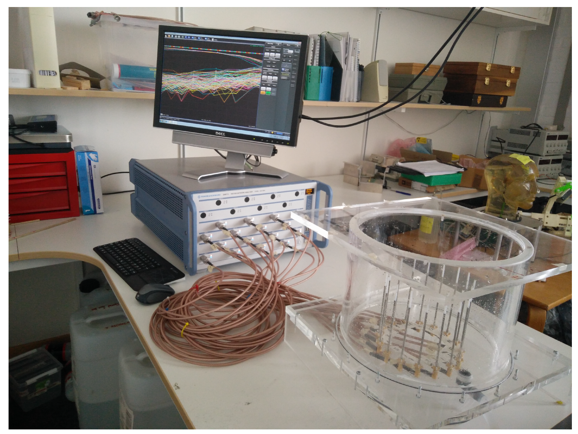
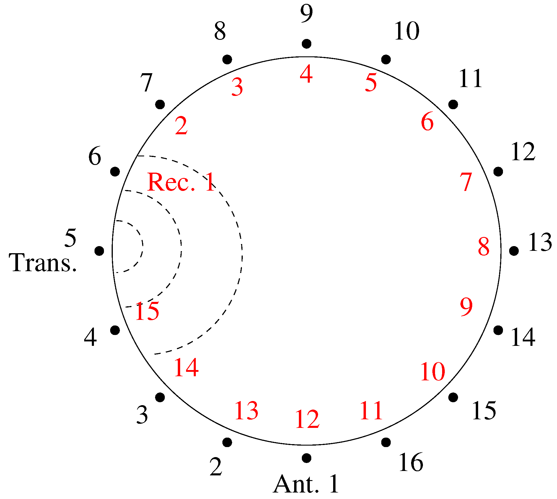
2.1. The System
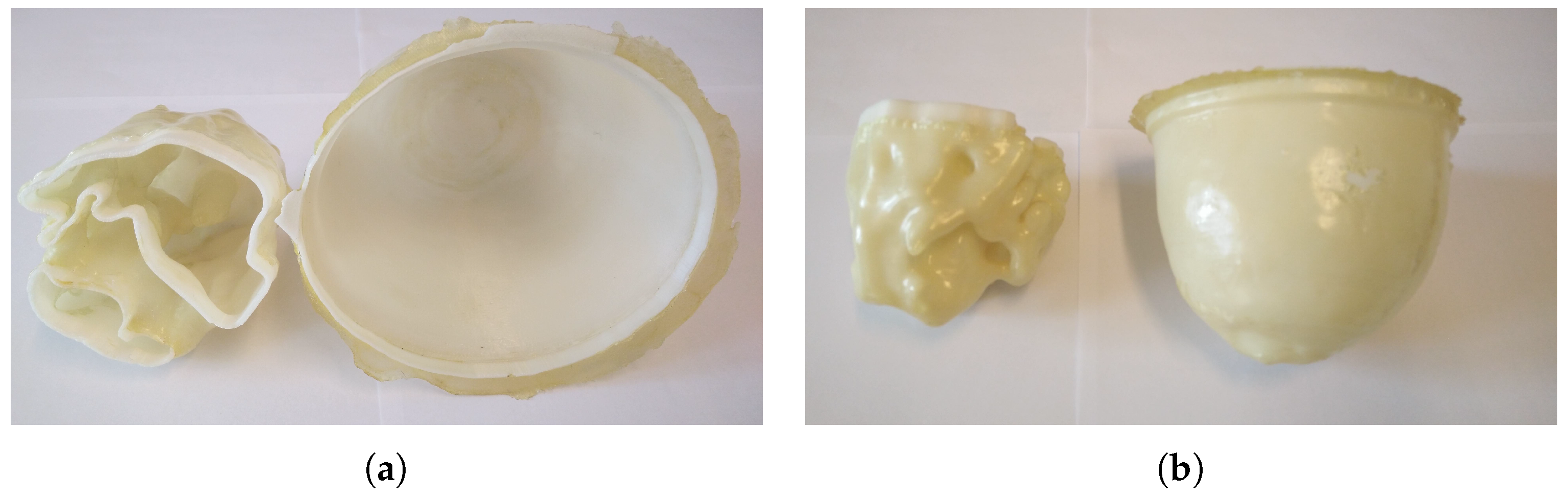
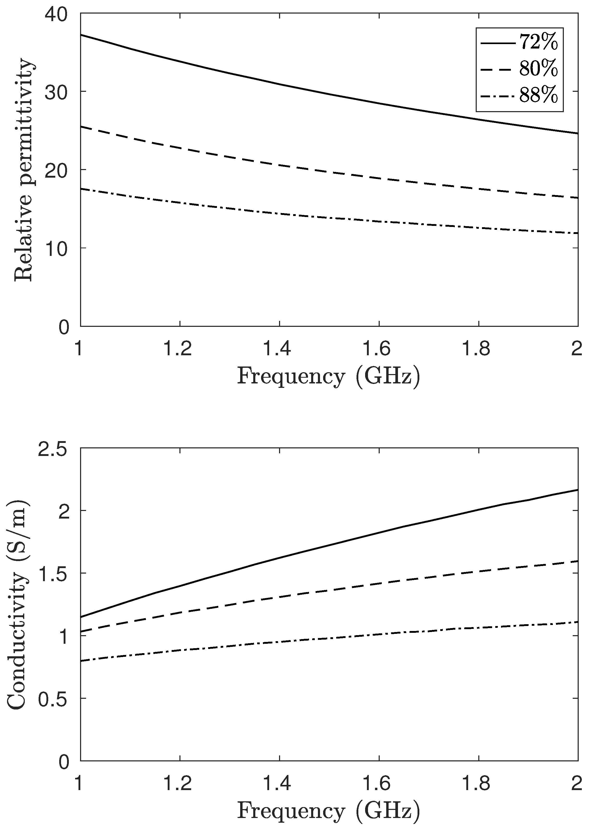
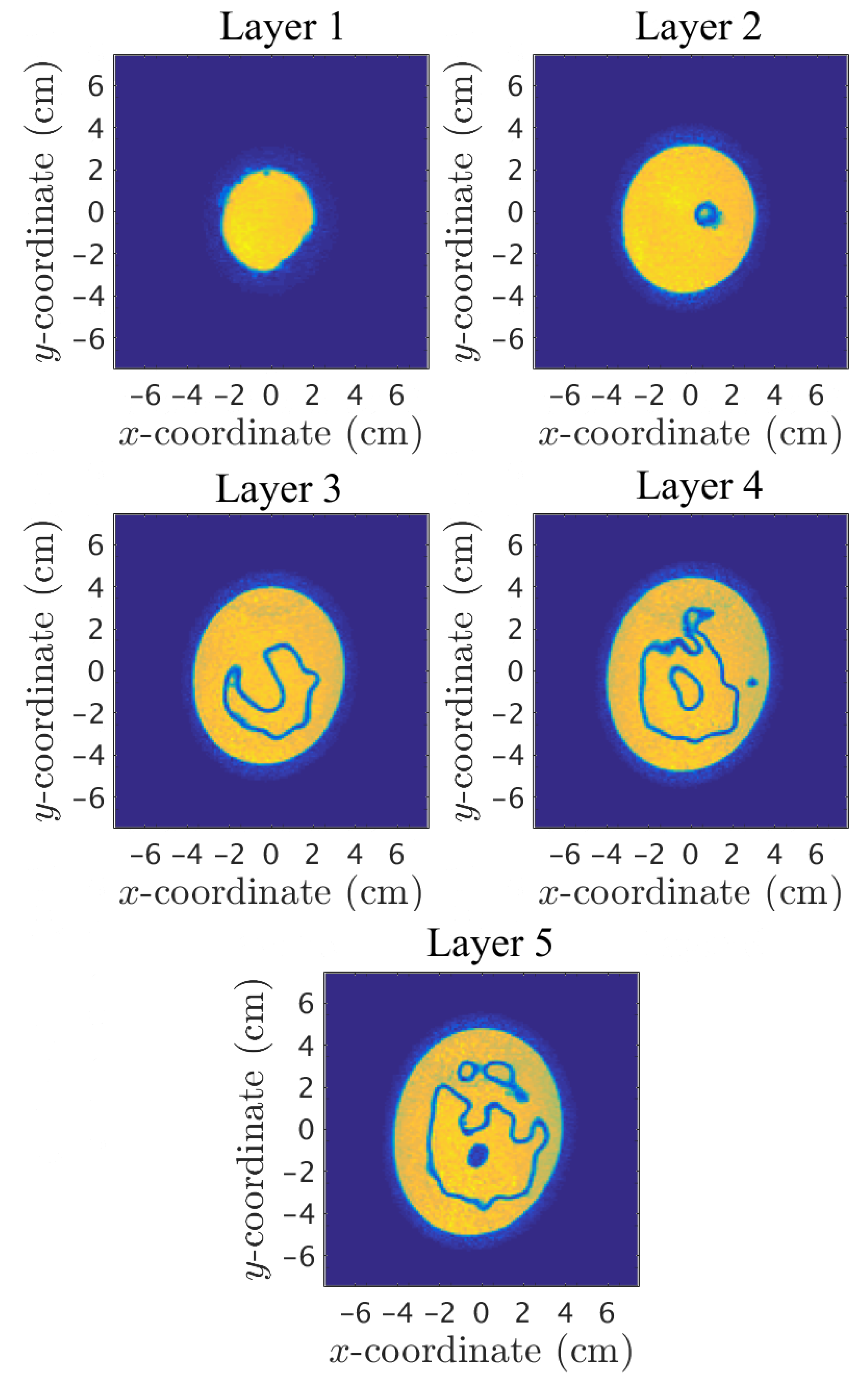
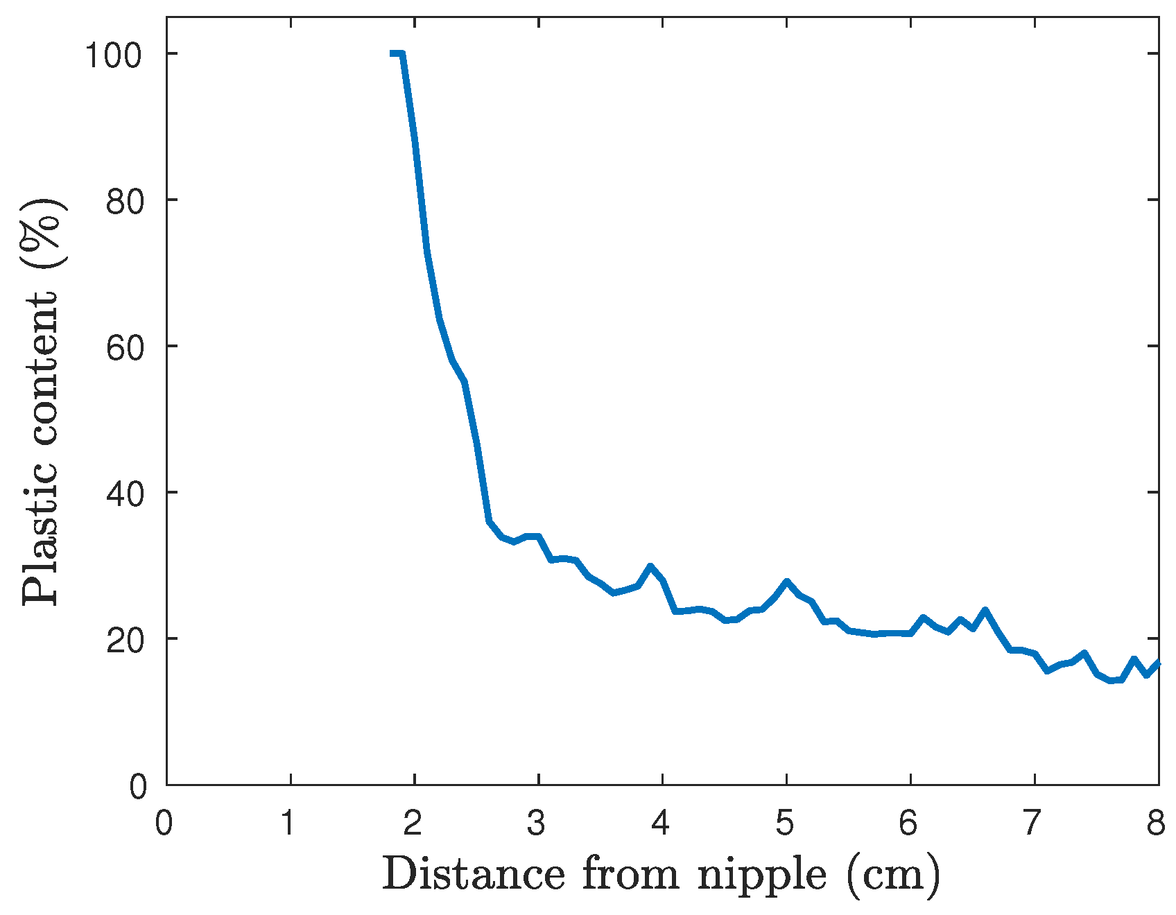
2.2. The Phantom
2.3. Inverse Problem
2.4. Measurements
3. Results
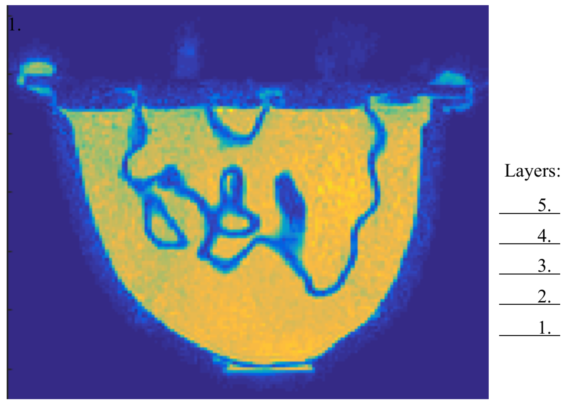
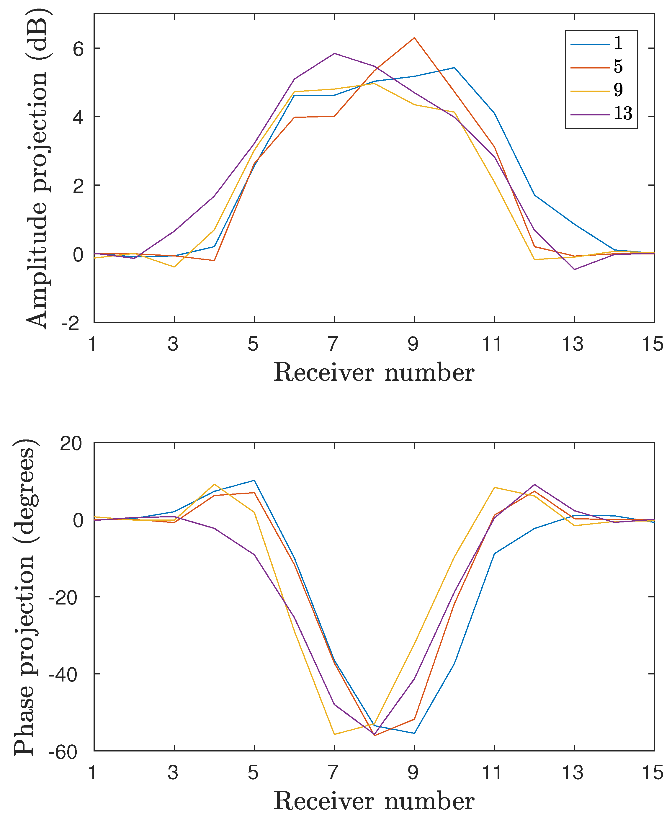
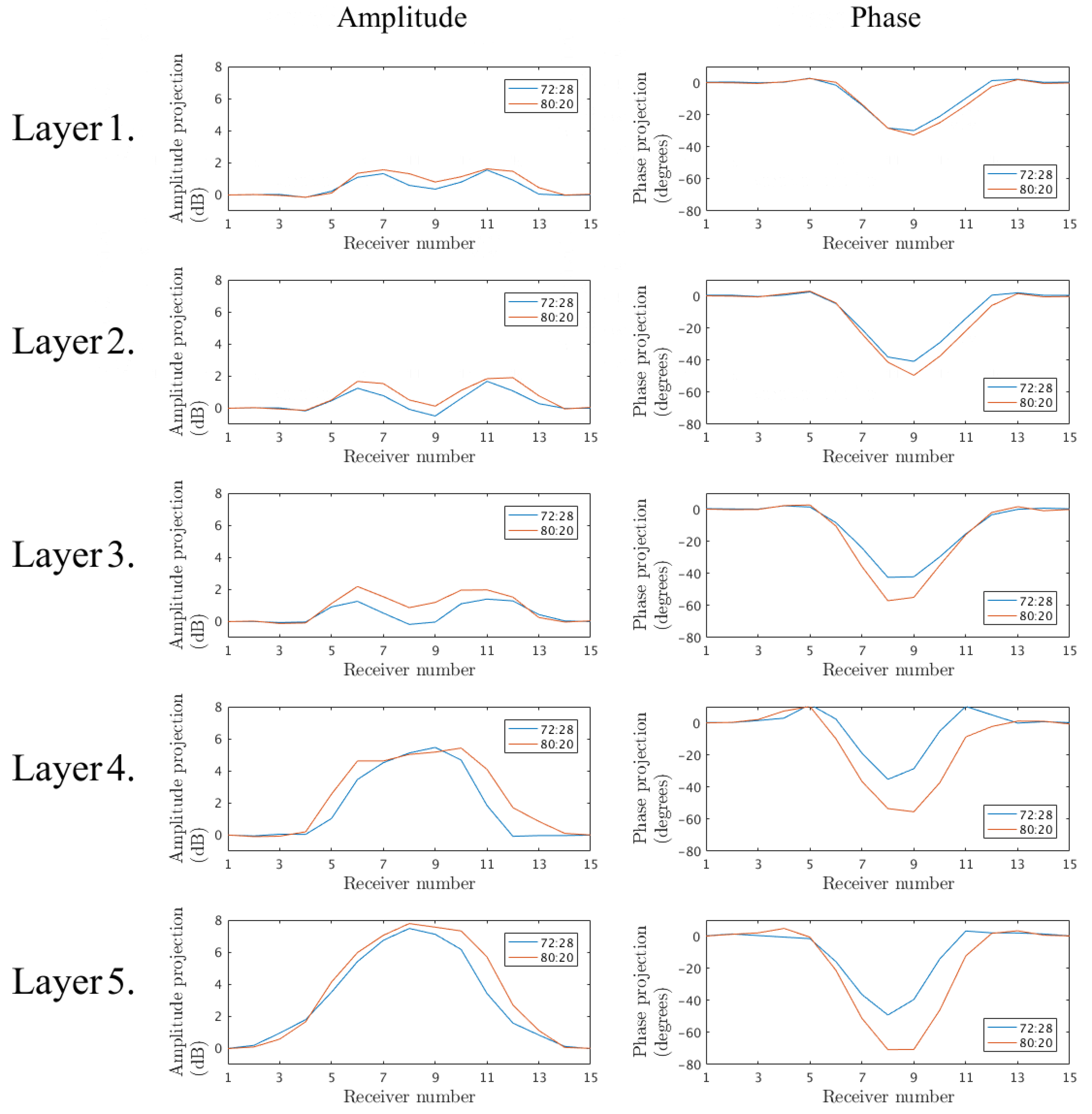
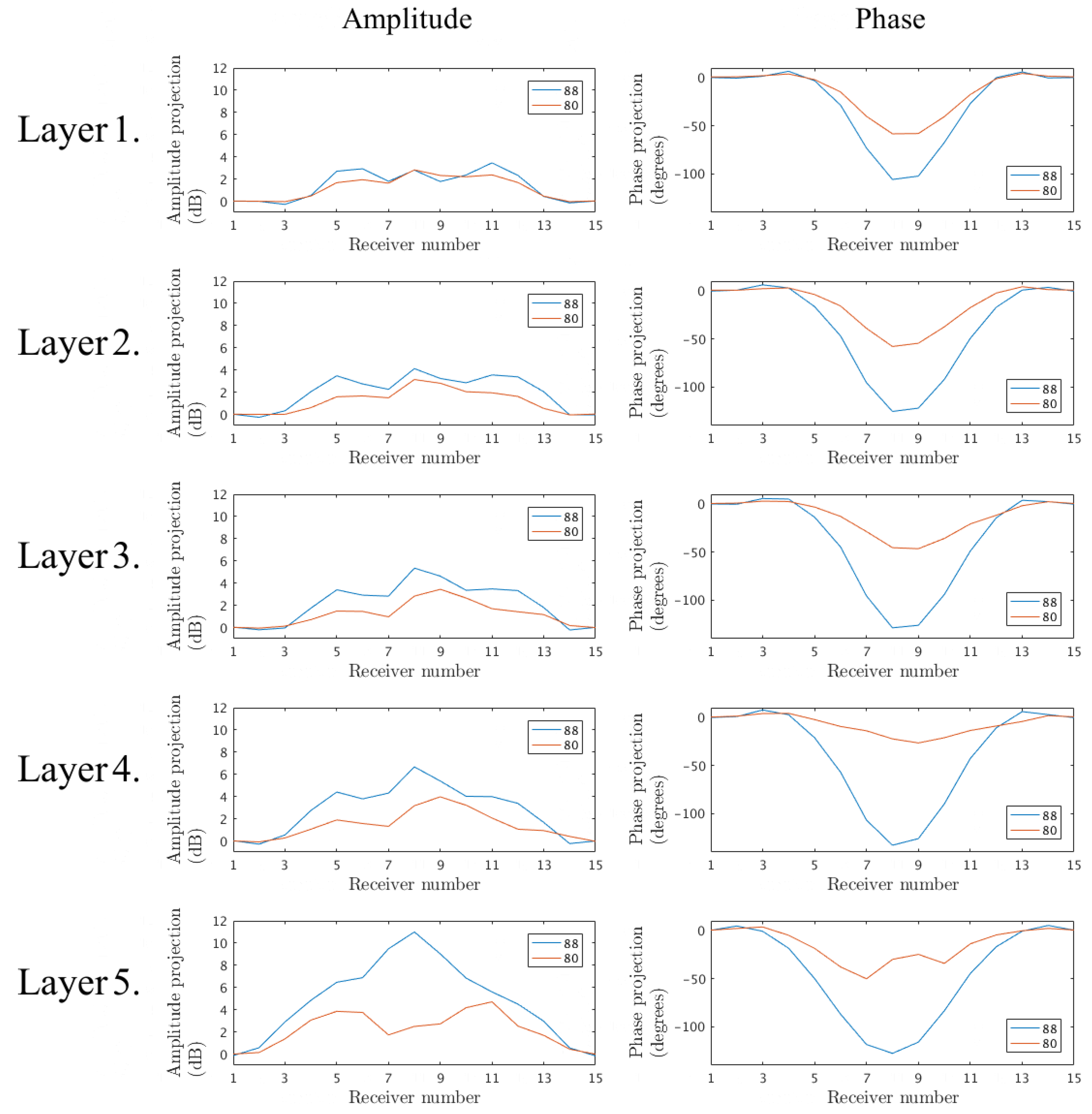
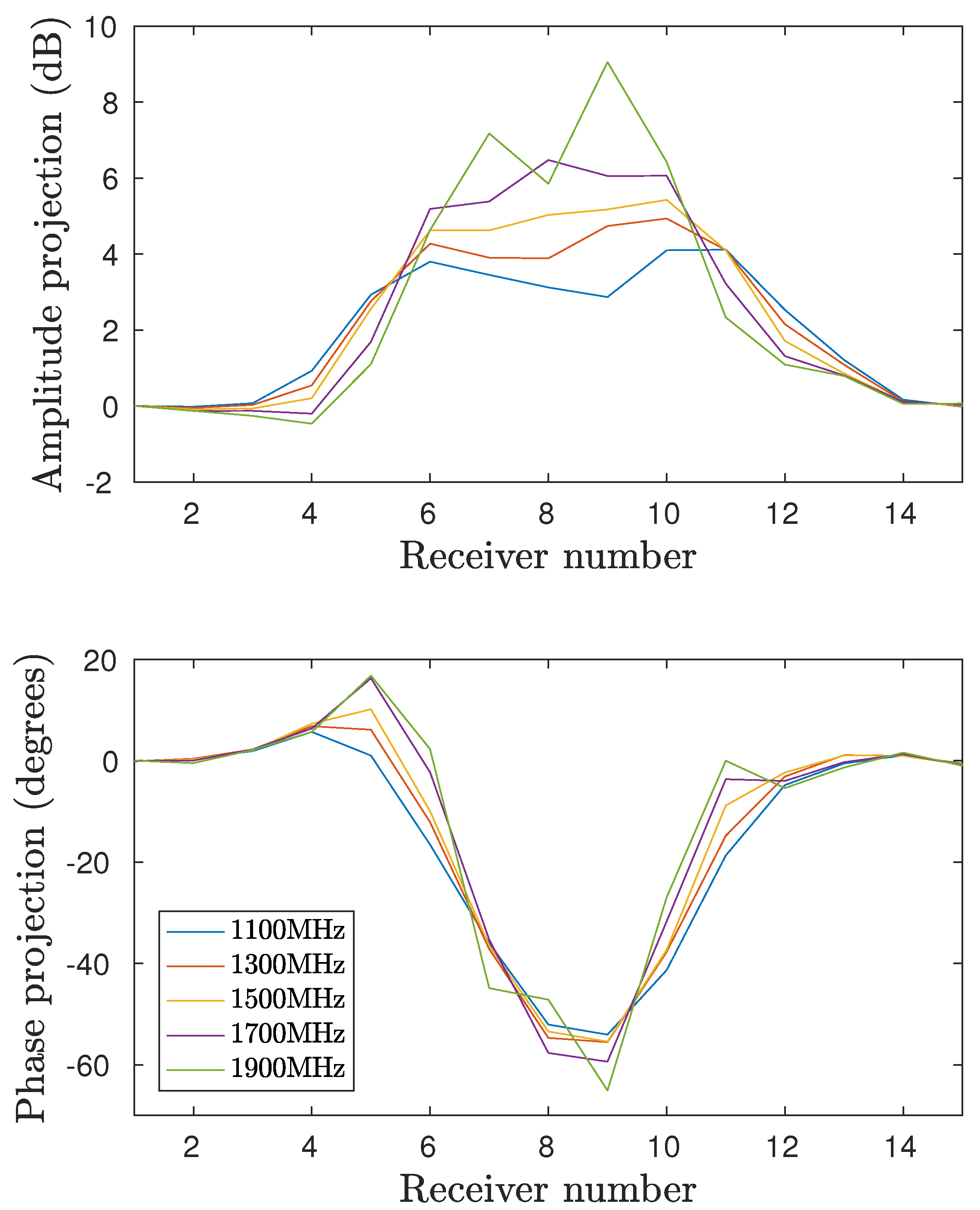
3.1. Amplitude and Phase Projections
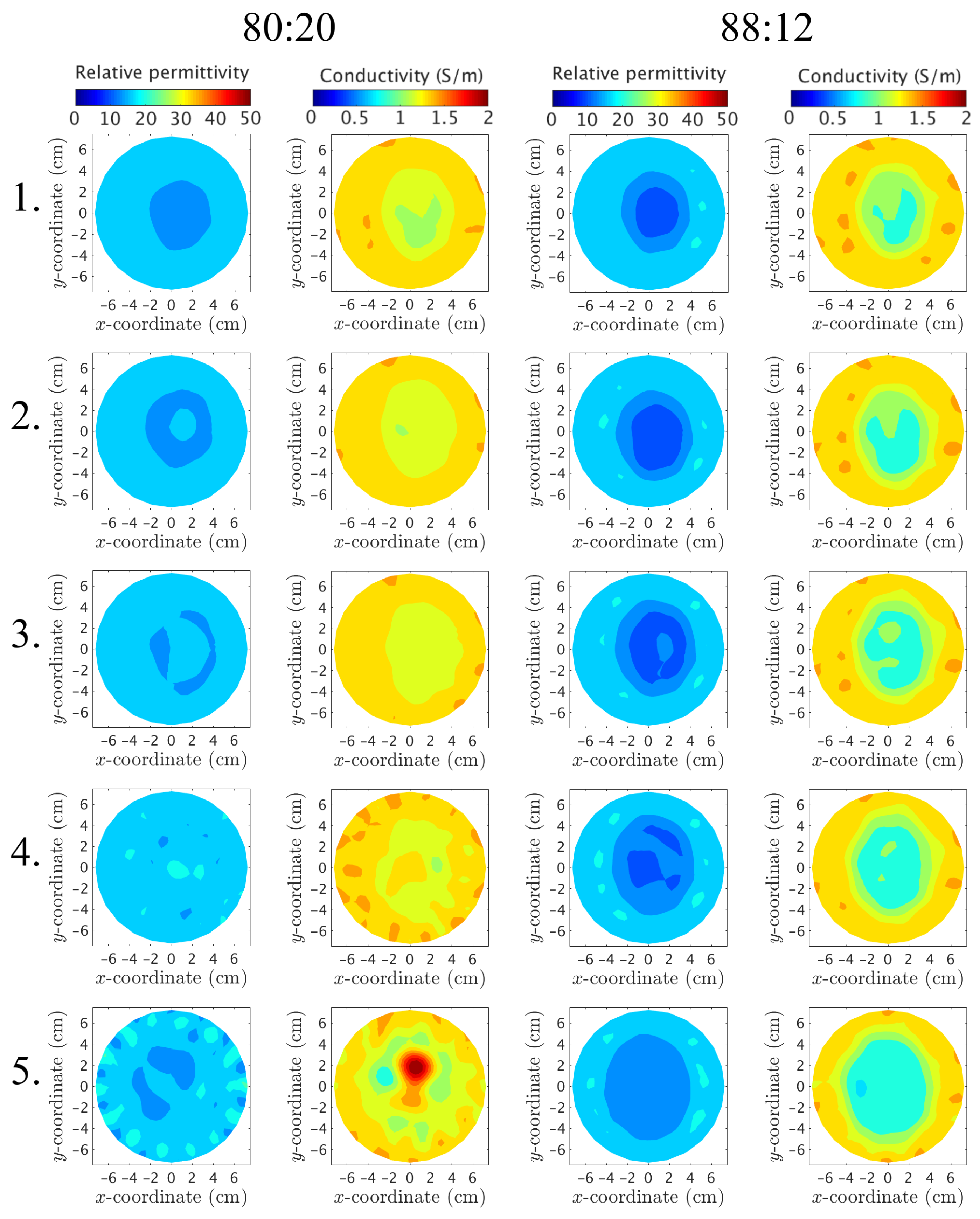
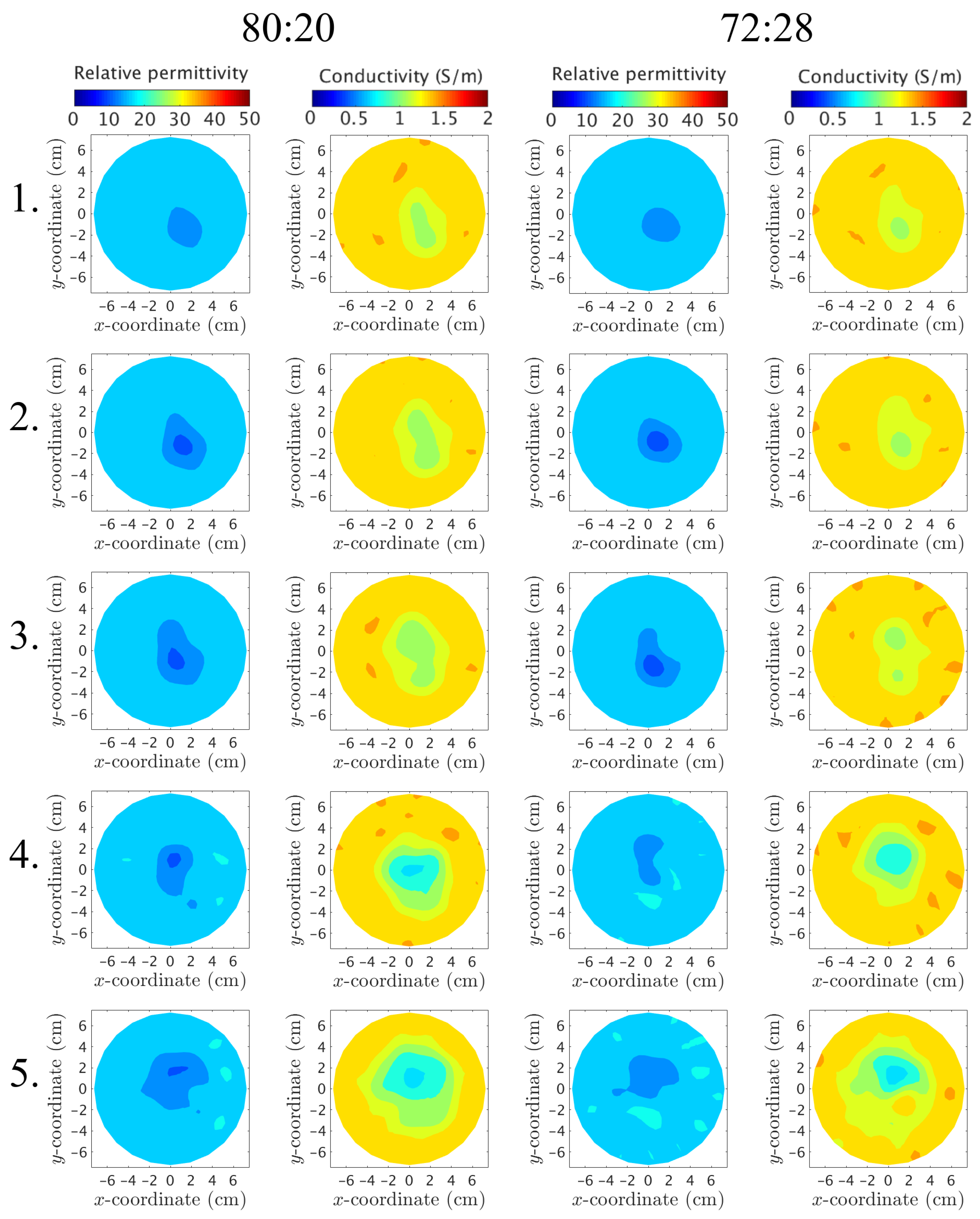
3.2. Image Reconstructions
4. Discussion
Author Contributions
Funding
Acknowledgments
Conflicts of Interest
References
- Meaney, P.M.; Goodwin, D.; Golnabi, A.H.; Zhou, T.; Pallone, M.; Geimer, S.D.; Burke, G.; Paulsen, K.D. Clinical Microwave Tomographic Imaging of the Calcaneus: A First-in-Human Case Study of Two Subjects. IEEE Trans. Biomed. Eng. 2012, 59, 3304–3313. [Google Scholar] [CrossRef] [PubMed]
- Persson, M.; Fhager, A.; Trefna, H.D.; Yu, Y.; McKelvey, T.; Pegenius, G.; Karlsson, J.E.; Elam, M. Microwave-Based Stroke Diagnosis Making Global Prehospital Thrombolytic Treatment Possible. IEEE Trans. Biomed. Eng. 2014, 61, 2806–2817. [Google Scholar] [CrossRef] [PubMed]
- Semenov, S.Y.; Corfield, D.R. Microwave Tomography for Brain Imaging: Feasibility Assessment for Stroke Detection. Int. J. Antennas Propag. 2008, 2008, 254830. [Google Scholar] [CrossRef]
- Semenov, S.Y.; Bulyshev, A.E.; Posukh, V.G.; Sizov, Y.E.; Williams, T.C.; Souvorov, A.E. Microwave tomography for detection/imaging of myocardial infarction. I. Excised canine hearts. Ann. Biomed. Eng. 2003, 31, 262–270. [Google Scholar] [CrossRef] [PubMed]
- Fhager, A.; Gustafsson, M.; Nordebo, S. Image Reconstruction in Microwave Tomography Using a Dielectric Debye Model. IEEE Trans. Biomed. Eng. 2012, 59, 156–166. [Google Scholar] [CrossRef] [PubMed]
- Meaney, P.M.; Golnabi, A.H.; Epstein, N.R.; Geimer, S.D.; Fanning, M.W.; Weaver, J.B.; Paulsen, K.D. Integration of microwave tomography with magnetic resonance for improved breast imaging. Med. Phys. 2013, 40, 103101-1–103101-13. [Google Scholar] [CrossRef] [PubMed]
- Klemm, M.; Leendertz, J.A.; Gibbins, D.; Craddock, I.J.; Preece, A.; Benjamin, R. Microwave Radar-Based Breast Cancer Detection: Imaging in Inhomogeneous Breast Phantoms. IEEE Antennas Wirel. Propag. Lett. 2009, 8, 1349–1352. [Google Scholar] [CrossRef]
- Fear, E.C.; Bourqui, J.; Curtis, C.; Mew, D.; Docktor, B.; Romano, C. Microwave breast imaging with a monostatic radar-based system: A study of application to patients. IEEE Trans. Microw. Theory Tech. 2013, 61, 2119–2128. [Google Scholar] [CrossRef]
- Porter, E.; Coates, M.; Popovic, M. An early clinical study of time-domain microwave radar for breast health monitoring. IEEE Trans. Biomed. Eng. 2016, 63, 530–539. [Google Scholar] [CrossRef] [PubMed]
- Amineh, R.K.; Khalatpour, A.; Nikolova, N.K. Three-dimensional microwave holographic imaging using co- and cross-polarized data. IEEE Trans. Antennas Propag. 2012, 60, 3526–3531. [Google Scholar] [CrossRef]
- Scapaticci, R.; Catapano, I.; Crocco, L. Wavelet-based adaptive multiresolution inversion for quantitative microwave imaging of breast tissue. IEEE Trans. Antennas Propag. 2012, 60, 3717–3726. [Google Scholar] [CrossRef]
- Shea, J.D.; Kosmas, P.; Hagness, S.C.; van Veen, B.D. Three-dimensional microwave imaging of realistic numerical breast phantoms via a multiple-frequency inverse scattering technique. Med. Phys. 2010, 37, 4210–4226. [Google Scholar] [CrossRef] [PubMed]
- Meaney, P.M.; Kaufman, P.A.; Muffly, L.S.; Click, M.; Poplack, S.P.; Wells, W.A.; Schwartz, G.N.; di Florio-Alexander, R.M.; Tosteson, T.D.; Li, Z.; et al. Microwave imaging for neoadjuvant chemotherapy monitoring: Initial clinical experience. Breast Cancer Res. 2013, 15, R35. [Google Scholar] [CrossRef] [PubMed]
- Poplack, S.P.; Tosteson, T.D.; Wells, W.A.; Pogue, B.W.; Meaney, P.M.; Hartov, A.; Kogel, C.A.; Soho, S.K.; Gibson, J.J.; Paulsen, K.D. Electromagnetic breast imaging: Results of a pilot study in women with abnormal mammograms. Radiology 2007, 243, 350–359. [Google Scholar] [CrossRef] [PubMed]
- Preece, A.W.; Craddock, I.; Shere, M.; Jones, L.; Winton, H.L. MARIA M4: Clinical evaluation of a prototype ultrawideband radar scanner for breast cancer detection. J. Med. Imaging 2016, 3, 033502. [Google Scholar] [CrossRef] [PubMed]
- Siegel, R.L.; Miller, K.D.; Jemal, A. Cancer statistics, 2018. CA Cancer J. 2018, 68, 7–30. [Google Scholar] [CrossRef] [PubMed]
- Joy, J.E.; Penhoet, E.E.; Petitti, D.B. (Eds.) Saving Women’s Lives: Strategies for Improving Breast Cancer Detection and Diagnosis; The National Academies Press: Washington, DC, USA, 2005. [Google Scholar]
- Sugitani, T.; Kubota, S.i.; Kuroki, S.i.; Sogo, K.; Arihiro, K.; Okada, M.; Kadoya, T.; Hide, M.; Oda, M.; Kikkawa, T. Complex permittivities of breast tumor tissues obtained from cancer surgeries. Appl. Phys. Lett. 2014, 104, 253702-1–253702-5. [Google Scholar] [CrossRef]
- Martellosio, A.; Pasian, M.; Bozzi, M.; Perregrini, L.; Mazzanti, A.; Svelto, F.; Summers, P.E.; Renne, G.; Preda, L.; Bellomi, M. Dielectric Properties Characterization From 0.5 to 50 GHz of Breast Cancer Tissues. IEEE Trans. Microw. Theory Tech. 2017, 65, 998–1011. [Google Scholar] [CrossRef]
- Cheng, Y.; Fu, M. Dielectric properties for non-invasive detection of normal, benign, and malignant breast tissues using microwave theories. Thorac. Cancer 2018, 9, 459–465. [Google Scholar] [CrossRef] [PubMed]
- Woodard, H.Q.; White, D.R. The composition of body tissues. Br. J. Radiol. 1986, 59, 1209–1219. [Google Scholar] [CrossRef] [PubMed]
- Lazebnik, M.; Madsen, E.; Frank, G.R.; Hagness, S.C. Tissue-mimicking phantom materials for narrowband and ultrawideband microwave applications. Phys. Med. Biol. 2005, 50, 4245–4258. [Google Scholar] [CrossRef] [PubMed]
- Joachimowicz, N.; Conessa, C.; Henriksson, T.; Duchêne, B. Breast Phantoms for Microwave Imaging. IEEE Antennas Wirel. Propag. Lett. 2014, 13, 1333–1336. [Google Scholar] [CrossRef]
- Santorelli, A.; Laforest, O.; Porter, E.; Popović, M. Image classification for a time-domain microwave radar system: Experiments with stable modular breast phantoms. In Proceedings of the 9th European Conference on Antennas and Propagation (EuCAP), Lisbon, Portugal, 13–17 April 2015. [Google Scholar]
- Meaney, P.M.; Fox, C.J.; Geimer, S.D.; Paulsen, K.D. Electrical characterization of glycerin: Water mixtures and the implications for use as a coupling medium in microwave tomography. IEEE Trans. Microw. Theory Tech. 2017, 65, 1471–1478. [Google Scholar] [CrossRef] [PubMed]
- Lazebnik, M.; Popovic, D.; McCartney, L.; Watkins, C.B.; Lindstrom, M.J.; Harter, J.; Sewall, S.; Ogilvie, T.; Magliocco, A.; Breslin, T.M.; et al. A large-scale study of the ultrawideband microwave dielectric properties of normal, benign and malignant breast tissues obtained from cancer surgeries. Phys. Med. Biol. 2007, 52, 6093–6115. [Google Scholar] [CrossRef] [PubMed]
- Gabriel, S.; Lau, R.W.; Gabriel, C. The dielectric properties of biological tissues: II. Measurements in the frequency range 10 Hz to 20 GHz. Phys. Med. Biol. 1996, 41, 2251–2269. [Google Scholar] [CrossRef] [PubMed]
- Burfeindt, M.J.; Colgan, T.J.; Mays, R.O.; Shea, J.D.; Behdad, N.; Veen, B.D.V.; Hagness, S.C. MRI-Derived 3-D-Printed Breast Phantom for Microwave Breast Imaging Validation. IEEE Antennas Wirel. Propag. Lett. 2012, 11, 1610–1613. [Google Scholar] [CrossRef] [PubMed]
- Joachimowicz, N.; Duchêne, B.; Conessa, C.; Meyer, O. Easy-to-produce adjustable realistic breast phantoms for microwave imaging. In Proceedings of the 10th European Conference on Antennas and Propagation (EuCAP), Davos, Switzerland, 10–15 April 2016. [Google Scholar]
- Herrera, D.R.; Reimer, T.; Nepote, M.S.; Pistorius, S. Manufacture and testing of anthropomorphic 3D-printed breast phantoms using a microwave radar algorithm optimized for propagation speed. In Proceedings of the 11th European Conference on Antennas and Propagation (EuCAP), Paris, France, 19–24 March 2017. [Google Scholar]
- Rydholm, T.; Fhager, A.; Persson, M.; Meaney, P.M. A First Evaluation of the Realistic Supelec-Breast Phantom. IEEE J. ERM 2017, 1, 59–65. [Google Scholar] [CrossRef]
- Epstein, N.R.; Meaney, P.M.; Paulsen, K.D. 3D parallel-detection microwave tomography for clinical breast imaging. Rev. Sci. Instrum. 2014, 85, 124704. [Google Scholar] [CrossRef] [PubMed]
- Meaney, P.M.; Schubitidze, F.; Fanning, M.W.; Kmiec, M.; Epstein, N.; Paulsen, K.D. Surface-wave multipath signals in near-field microwave imaging. Int. J. Biomed. Imaging 2012, 2012, 697253. [Google Scholar] [CrossRef] [PubMed]
- Meaney, P.M.; Geimer, S.D.; Paulsen, K.D. Two-step inversion in microwave imaging with a logarithmic transformation. Med. Phys. 2017, 44, 4239–4251. [Google Scholar] [CrossRef] [PubMed]
- UWCEM-Phantom Repository. Available online: http://uwcem.ece.wisc.edu/phantomRepository.html (accessed on 3 July 2017).
- Vasquez, J.A.T.; Vipiana, F.; Casu, M.R.; Vacca, M.; Sarwar, I.; Scapaticci, R.; Joachimowicz, N.; Duchêne, B. Experimental assessment of qualitative microwave imaging using a 3-D realistic breast phantom. In Proceedings of the 11th European Conference on Antennas and Propagation (EuCAP), Paris, France, 19–24 March 2017. [Google Scholar]
- Koutsoupidou, M.; Karanasiou, I.S.; Kakoyiannis, C.G.; Groumpas, E.; Conessa, C.; Joachimowicz, N.; Duchêne, B. Evaluation of a tumor detection microwave system with a realistic breast phantom. Microw. Opt. Technol. Lett. 2016, 59, 6–10. [Google Scholar] [CrossRef]
- Joachimowicz, N.; Duchêne, B.; Conessa, C.; Meyer, O. Reference phantoms for microwave imaging. In Proceedings of the 11th European Conference on Antennas and Propagation (EuCAP), Paris, France, 19–24 March 2017. [Google Scholar]
- Meaney, P.M.; Fanning, M.W.; Raynolds, T.; Fox, C.J.; Fang, Q.; Kogel, C.A.; Poplack, S.P.; Paulsen, K.D. Initial Clinical Experience with Microwave Breast Imaging in Women with Normal Mammography. Acad. Radiol. 2007, 14, 207–218. [Google Scholar] [CrossRef] [PubMed]
- Meaney, P.M.; Yagnamurthy, N.K.; Paulsen, K.D. Pre-scaled two-parameter Gauss-Newton image reconstruction to reduce property recovery imbalance. Phys. Med. Biol. 2002, 47, 1101–1119. [Google Scholar] [CrossRef] [PubMed]
- Faenger, B.; Ley, S.; Helbig, M.; Sachs, J.; Hilger, I. Breast phantom with a conductive skin layer and conductive 3D-printed anatomical structures for microwave imaging. In Proceedings of the 11th European Conference on Antennas and Propagation (EuCAP), Paris, France, 19–24 March 2017. [Google Scholar]


| Series | A | B | C | D |
|---|---|---|---|---|
| Outer chamber | 88 | 80 | * | * |
| Inner chamber | * | * | 72 | 80 |
© 2018 by the authors. Licensee MDPI, Basel, Switzerland. This article is an open access article distributed under the terms and conditions of the Creative Commons Attribution (CC BY) license (http://creativecommons.org/licenses/by/4.0/).
Share and Cite
Rydholm, T.; Fhager, A.; Persson, M.; Geimer, S.D.; Meaney, P.M. Effects of the Plastic of the Realistic GeePS-L2S-Breast Phantom. Diagnostics 2018, 8, 61. https://doi.org/10.3390/diagnostics8030061
Rydholm T, Fhager A, Persson M, Geimer SD, Meaney PM. Effects of the Plastic of the Realistic GeePS-L2S-Breast Phantom. Diagnostics. 2018; 8(3):61. https://doi.org/10.3390/diagnostics8030061
Chicago/Turabian StyleRydholm, Tomas, Andreas Fhager, Mikael Persson, Shireen D. Geimer, and Paul M. Meaney. 2018. "Effects of the Plastic of the Realistic GeePS-L2S-Breast Phantom" Diagnostics 8, no. 3: 61. https://doi.org/10.3390/diagnostics8030061
APA StyleRydholm, T., Fhager, A., Persson, M., Geimer, S. D., & Meaney, P. M. (2018). Effects of the Plastic of the Realistic GeePS-L2S-Breast Phantom. Diagnostics, 8(3), 61. https://doi.org/10.3390/diagnostics8030061