Article

Grasp Point Optimization and Leakage-Compliant Dimensioning of Energy-Efficient Vacuum-Based Gripping Systems

Institute of Machine Tools and Production Technology, Technische Universität Braunschweig, Langer Kamp 19b, 38106 Braunschweig, Germany
*
Author to whom correspondence should be addressed.
Machines 2021, 9(8), 149; https://doi.org/10.3390/machines9080149
Submission received: 26 May 2021 / Revised: 27 July 2021 / Accepted: 28 July 2021 / Published: 29 July 2021
(This article belongs to the Section Automation and Control Systems)

Abstract

:
Vacuum-based handling, used in many applications and industries, offers great flexibility and fast handling processes. However, due to significant energy conversion losses from electrical energy to the useable suction flow, vacuum-based handling is highly energy-inefficient. In preliminary work, we showed that our grasp optimization method offers the potential to save at least 50% of energy by a targeted placement of individual suction cups on the part to be handled. By considering the leakage between gripper and object, this paper aims to extend the grasp optimization method by predicting the effective compressed air consumption depending on object surface roughness, gripper diameter and gripper count. Through balancing of the target pressure difference and the leakage tolerance in combination with the gripper count and gripper diameter, significant reductions of the compressed air, use and therefore the overall energy consumption, can be achieved. With knowledge about the gripper-specific leakage behavior, in the future it will be straightforward for system integrators to minimize the need for oversizing due to process-related uncertainties and therefore to provide application-specific and energy-optimized handling solutions to their customers.

1. Introduction

Vacuum-based handling systems are widely used in warehouse automation and industrial production environments, e.g., in automotive production [1]. Automated parts handling in general adds up to about 50% of all robot-guided processes in production systems [2], but is non-value-adding. In the particular case of vacuum-based handling, where the vacuum is usually generated by compressed air-supplied vacuum ejectors, significant energy losses occur along the energy conversion chain (Figure 1).
Therefore, already slight energy savings in the handling process can enable huge savings of the initially invested electrical energy [3]. Besides the development of isolated components [4] and the application-specific process planning and system configuration [5], one major field of activity aiming at increasing the energy-efficiency of vacuum-based handling processes is the targeted design of the gripping system. By using experimentally obtained knowledge about the gripper-object-specific achievable holding force, we demonstrated that for practically leakage-free vacuum-based gripping systems, about 50% of energy can easily be saved through a simple reduction of the desired pressure difference [6]. Present approaches for grasp planning in vacuum-based handling focus on a single vacuum cup [7,8] or on systems with two to four adjustable cups [9,10,11,12]. However, these approaches are rather specific with regard to their applicability which is disadvantageous for a both automated and transparent design process [13] (more detailed information on present research on grasp planning for vacuum-based handling is given in [6]). Hence, the model-based grasp optimization method proposed in [6] is potentially applicable to arbitrary shell-like parts and offers great potential of energy savings.
In the context of the multi-objective design optimization of gripping systems, various approaches can be found in literature. In [14], a combination of the augmented Lagrange multiplier and the simplex method is applied for optimizing the topology and size-shape of an adaptive compliant gripper. Grasp configuration planning for an underactuated three-fingered robot hand is realized via artificial neural networks in [15]. In [16], a design selection methodology for system-optimal compliant actuation is presented, which consists of a pareto-optimization and uses a homotopy approach, which relates new solutions to a known solutions and hence makes sure its feasibility. In the above mentioned research papers, the underlying optimization problems are characterized by a high complexity. For the problem of optimizing the grasp points for vacuum-based handling of a part, however, a simpler optimization method such as a genetic algorithm is estimated to offer the sufficient flexibility and capabilities.
In the scope of grasp planning, the leakage between gripper and object has not been considered, up to now. In [17] a general design approach for the dimensioning of temporary self-sufficient vacuum-based gripping systems is introduced, which is based on system-specific leakage properties of pre-defined gripping systems that are obtained in [18]. Here, also the surface roughness was considered for determining the resulting leakage. For the control of passive vacuum grippers, the leakage is implicitly considered in a closed-loop control system in [19]. In [20] the leakage is used in order to design the most adequate gripping system for bin picking of various objects.
Since leakage has not been taken into account for grasp optimization in vacuum-based handling, this paper aims to demonstrate that significant energy savings can be achieved by combining model-based grasp optimization with leakage-specific dimensioning of the gripping system parameters (such as number and diameter of grippers). Compared to the present state of the art, the novelty of our combined optimization approach is not characterized by the application of new complex optimization methods but lies in using data, that can be acquired at a low experimental effort, for a knowledge-based design of the vacuum-based gripping system which can otherwise only be roughly estimated based on prior experience.
In Section 2, firstly, the extended method for grasp point optimization and leakage-compliant gripping system dimensioning is introduced. In the following, it is examined if the object surface roughness is relevant to the grasp optimization algorithm itself. Lastly in Section 2, the influence of gripper size on the resulting leakage between object and gripper is investigated. Section 3 presents the results of the combined grasp optimization and gripping system dimensioning method for a selected use case. In Section 4, the obtained results are discussed and conclusions for further work are given.

2. Materials and Methods

This section firstly elaborates the method for model-based grasp point optimization (Section 2.1). In extension of the optimization method introduced in preliminary work of the authors, the influence of the surface roughness on the achievable holding force is examined in Section 2.2. The influence of the surface roughness on the leakage between gripper and object is further investigated in Section 2.3 as basis for the combined method for grasp optimization and gripping system dimensioning introduced in Section 2.4.

2.1. Method for Model-Based Grasp Point Optimization

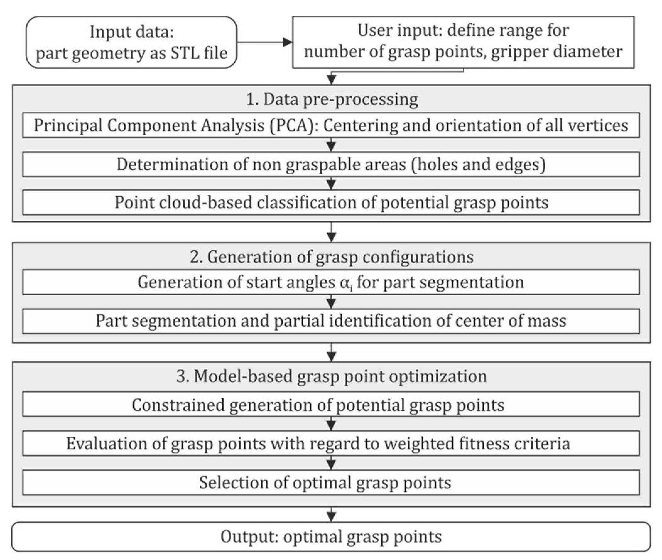
At a first step of the grasp optimization method (Figure 2), the part geometry is input to the algorithm as STL file. Since the STL file may be generated by a 3D scan, the geometry can potentially be oriented arbitrarily in space and must therefore be centered and re-oriented, which is realized by a principal component analysis (PCA). This step also comprises a projection of the 3D geometry to a 2D polygon, as a simplification for shell-like parts such as car body sheet metal parts. Such parts have a large area of a low thickness and mostly only local three-dimensional surface geometries, such that the macroscopic geometry is still most similar to a plane. The optimization procedure begins with the identification of the graspable area. This excludes edges and holes from the overall part geometry. In addition, potential grasp points in the graspable area are classified with regard to the main geometry (e.g., cylinder or dome) in order to estimate the achievable holding force within the optimization procedure. After these preparatory steps, the part geometry is divided into N segments, according to the gripper count N.
The gripper count and diameter are defined based on the expected process-specific forces at the gripper-part-interface in order to provide the required holding force. The mass distribution of the part is approximated by the equidistant distribution of mesh vertices. Due to the 3D to 2D projection, information about the real three-dimensional mass distribution are lost. The segmentation is implemented in such a way, that it slices the part by counting the mesh vertices in polar coordinates from a start angle α. If the part is graspable at the center of mass, the first segment (circular) is generated exactly at the center of mass, the remaining segments are generated as described above. The initial grasp points PI are then positioned in the mass center points of each segment, as initial solution for the optimization algorithm. Regardless of the part’s surface geometry, this would distribute the part’s mass evenly over the vacuum grippers. In order to cover the entire global solution space, not only one specific part segmentation is done, but the start angle for the polar coordinate-based vertex counting procedure is varied, resulting in P different segmentation variants. Further details on the segmentation can be found in [6].
In rare cases, it may be possible that the initial grasp points are located in the graspable area, hence the grippers can be positioned exactly at the initial grasp points 
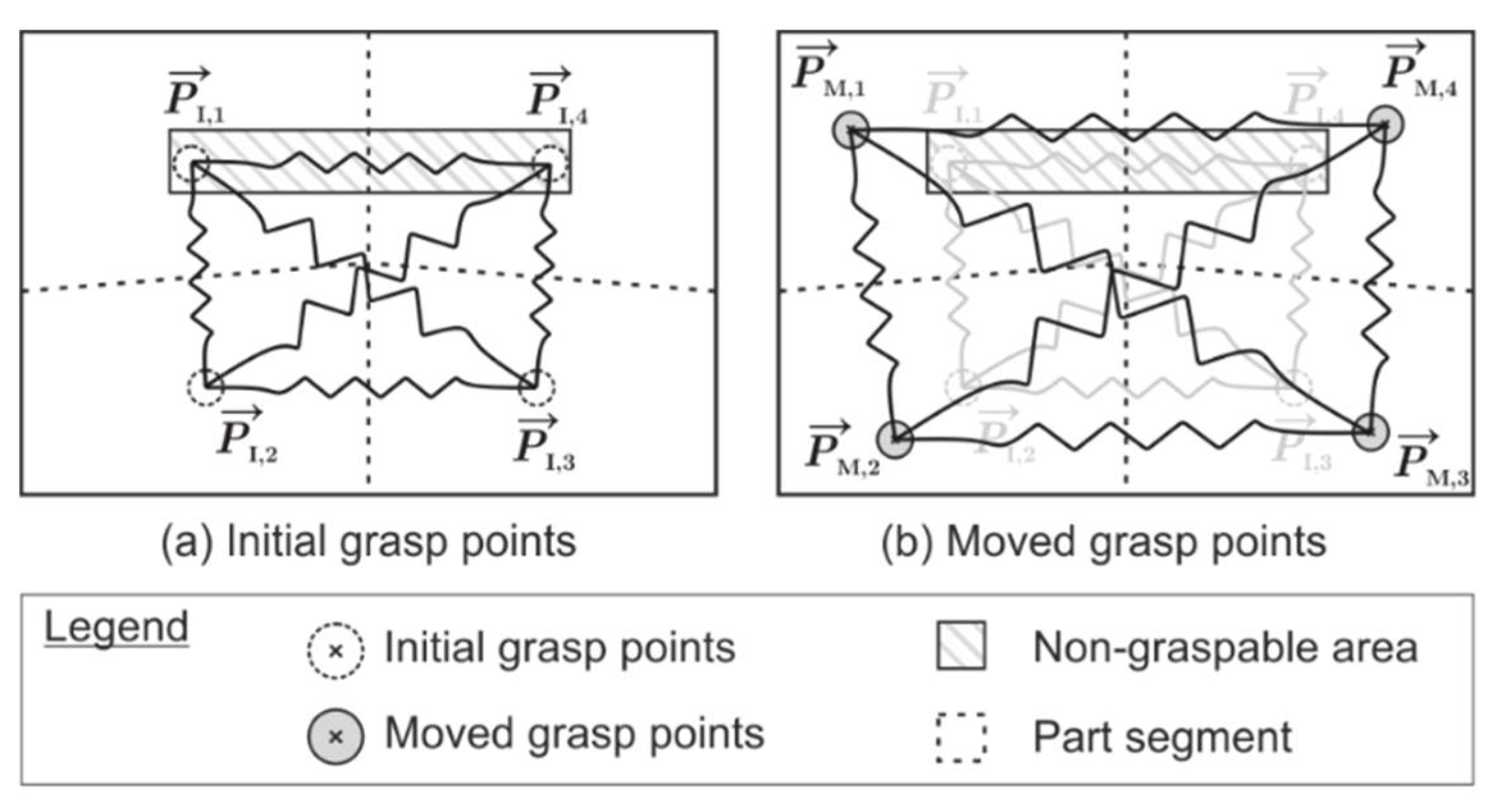
PI. However, this is unlikely for most cases. Hence, the initial grasp points must be moved to the graspable area. To evaluate if a certain combination of moved grasp points is feasible, three fitness criteria are introduced. Firstly, it is crucial that the eccentricity of each grasp point to the segment-wise mass center point is minimal in order to avoid additional moments of inertia, which would require to provide a higher holding force. Hence, the first criterion (distance criterion) can be derived by applying the principle of virtual work [21]. In specific, all grasp points are interconnected by non-elongated virtual springs (Figure 3a). If the position of any of the grasp points is changed, the virtual springs are elongated accordingly (Figure 3b).
Applying a virtual force Fi in order to elongate the spring by Δli requires to perform virtual work W i = F i Δ l i , where F i = c Δ l i and c is the spring stiffness. For all springs, the same stiffness c is selected in order to equally weight the influence of each spring for the fitness criterion and not prioritize certain point pairs. The spring elongation Δli can be represented by the distance between two grasp points that is added, when at least one of those two points is moved. Hence, in order to calculate the virtual work that must be performed by every grasp point PI in connection with all other grasp points, the following criterion is introduced (Equation (1)):
Criterion 1. Distance Criterion.
Minimize the distance between every initial grasp point PI and the corresponding shifted grasp point PM.
f 1 = i = 0 N k = 0 N P I , i P I , k P M , i P M , k 2
Secondly, it is crucial that the eccentricity of common center point of all aggregated grasp points to the part’s mass center point is minimal in order to minimize additional moments of inertia. This is limited by the following criterion (Equation (2)):
Criterion 2. Center of Mass Criterion.
Minimize the distance of the common center of mass of all moved grasp points to the center of mass.
f 2 = i = 0 N x i 2 + i = 0 N y i 2
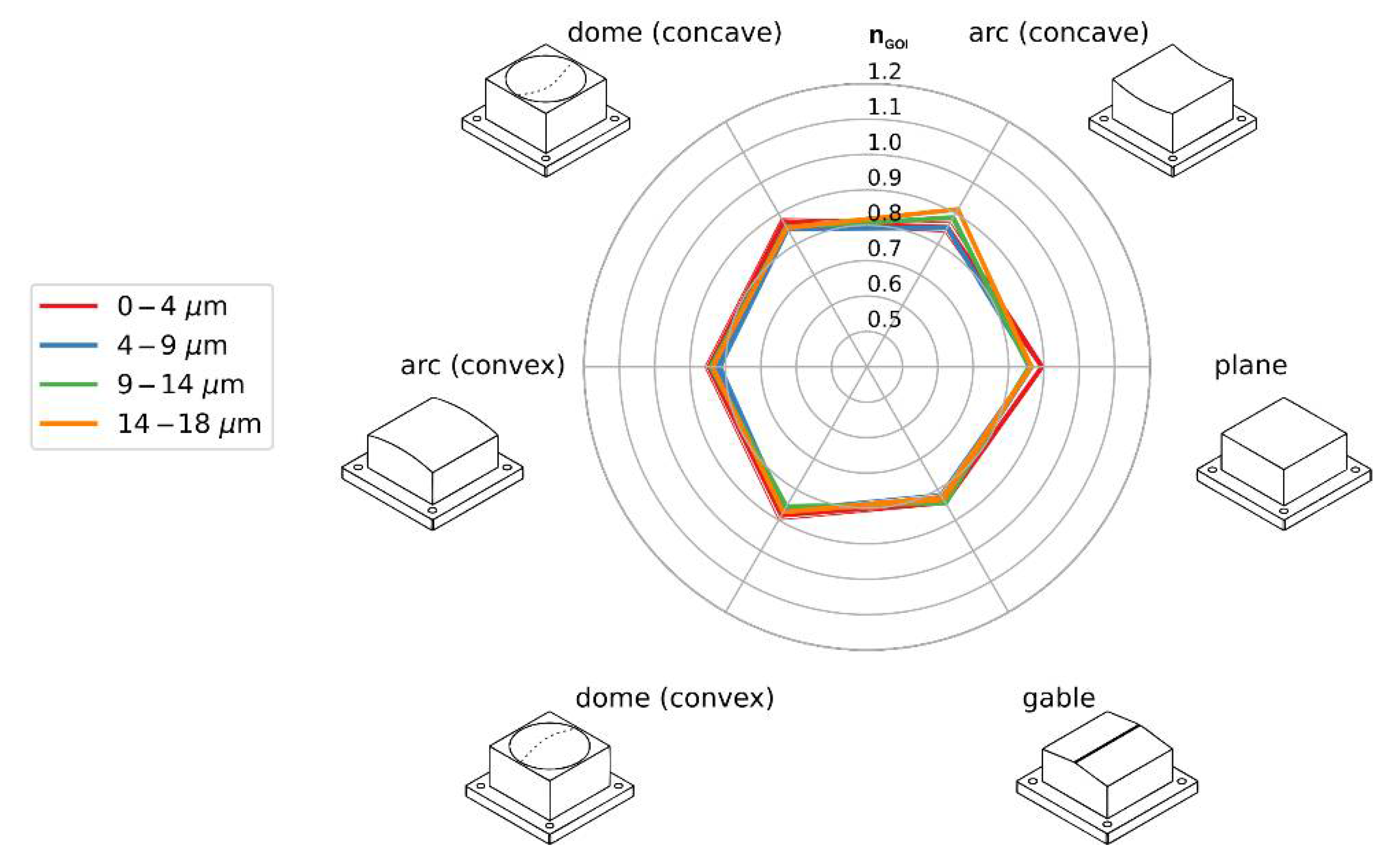
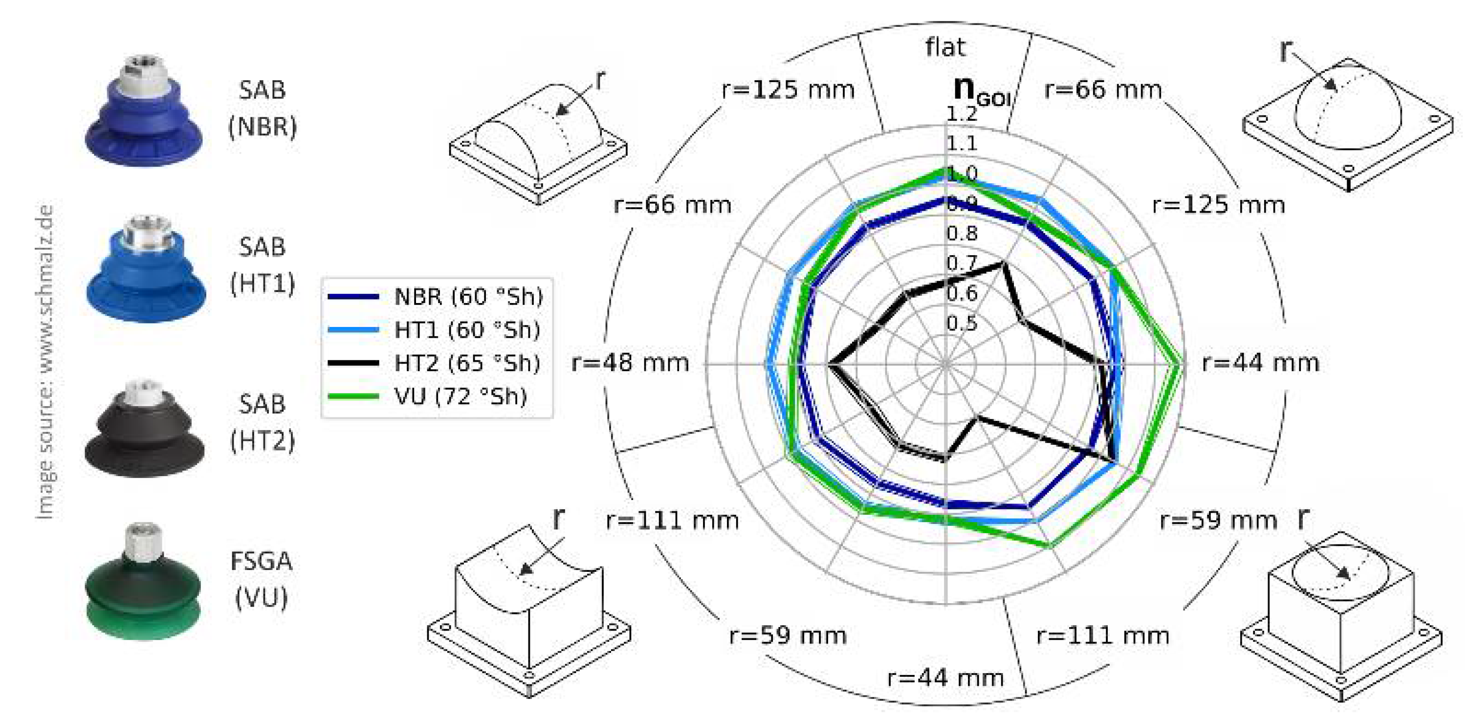
Thirdly, gripper-object-specific information considered in order to maximize the achievable holding force in normal load direction. In preliminary work, the obtained information about the achievable holding force was normalized by the maximum holding force information provided by the manufacturer, in order to quantify the actually achievable force for specific objects. The results of this preliminary work are depicted in Figure 4. The parameter nGOI describes the relation between the manufacturer provided values and the experimentally obtained information. For nGOI = 1, the specified force matches the experimental values, nGOI < 1 means that the experiments show smaller holding forces.
The third fitness criterion considers the gripper-object-specific values for nGOI and aims to maximize the achievable holding force for a given amount of grippers with a specified diameter (Equation (3)). The values of nGOI, that are specific to each possible grasp point within the graspable area, are provided as list to the algorithm.
Criterion 3. Formfit Criterion.
Maximize the achievable holding force.
f 3 = 1 / i = 0 N n G O I P M , i

2.2. Investigation of the Roughness-Dependent Maximum Holding Force

In preliminary work, the achievable holding force was investigated for specific combinations of surface geometry and gripper type in [3] and used in the optimization method [
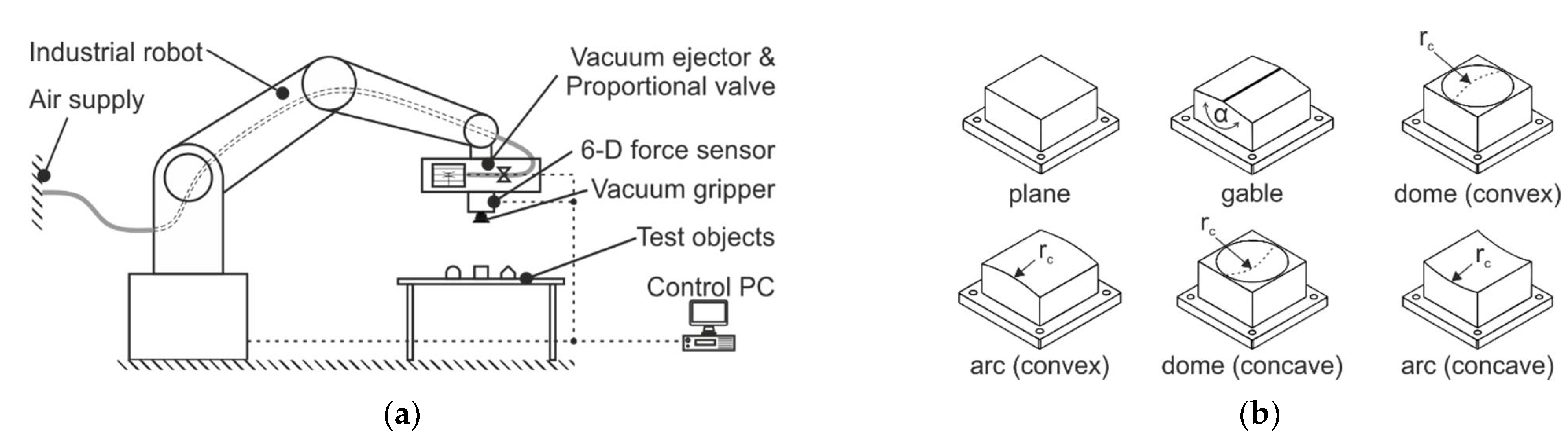
6] to evaluate the formfit criterion (Equation (3)). For the extended method introduced in this work, the influence of the object surface roughness is investigated. The used experimental setup is depicted in Figure 5a. For the roughness-specific experiments, six test object geometries were selected (Figure 5b) representing possible shapes of press-formed sheet metal: a plane as reference, a gable (α = 135°) with a 5 mm round, a convex dome (rc = 125 mm), a convex arc (rc = 125 mm), a concave dome (rc = 111 mm) and a concave arc (rc = 125 mm). rc is the curvature of the curved objects.
The experiments were conducted with one exemplary vacuum gripper with 1.5 foldings, made of SAB 60 nitrile butadiene rubber by J. Schmalz GmbH (Glatten, Germany). Since vacuum-based handling is extensively used in handling of sheet metal, e.g., in press shops in the automotive industry, a mean roughness range of 0.4 µm ≤ RZ ≤ 15 µm is taken into account, as this range is usually resulting from typical forming techniques such as deep-drawing [22]. In order to create multiple different values of the surface roughness within the regarded range of 0.4 to 15 µm, the test objects (test area 80 × 80 mm) were manufactured from aluminum, steel and PA6 and then ground (WIWOX EK 080 with grain size 150–212 µm, WIXOX GmbH, Erkrath, Germany). Four different roughness ranges resulted from exemplary roughness measurements. Five measurements were conducted per material with a Hommel Wave S10 skidded gage (Hommel GmbH, Cologne, Germany), with a T1E 2 µm probe tip and a test distance of 15 mm. The resulting mean values for the surface roughness (±standard deviation) are given in Table 1. From these measurements, discrete roughness ranges were derived for a straightforward generalization of the obtained results.
Resulting from the fabricated and grinded test objects, 24 different test objects are available for experiments (six object geometries, four roughness values). The objective of the experiments is to determine the maximum holding force. Firstly, the gripper is fully attached to the test object, evacuated by the used vacuum ejector and then pulled off completely at a velocity of 10 mm/s (in orientation to the test velocity for tensile testing of rubber [23]). Thirty repetitions were scheduled for each object, resulting in a total of 720 repetitions. These 720 repetitions were randomized in batches of six repetitions and then carried out fully automated in the above introduced robot-based test setup. Figure 6 shows the results of the roughness variation experiments. The comparison with the results obtained in [3] indicates that the influence of the roughness on the maximum holding force is relatively small and can therefore be neglected in the regarded range of 0.4 µm ≤ RZ ≤ 15 µm.
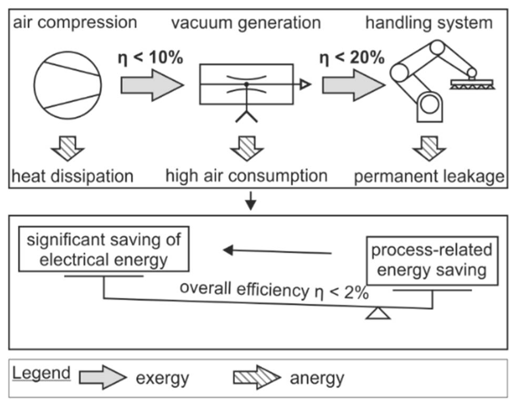
Although no significant influence of the surface roughness on the achievable holding force could be determined for the regarded roughness range, in the following section it is examined to what extent the surface roughness influences the leakage between gripper and object. This enables calculating the corresponding compressed air consumption for evacuating the dead volume (internal volume) of the gripping system and therefore dimensioning the gripping system in such a way, that the resulting compressed air consumption is minimized.

2.3. Investigation of the Influence of Surface Roughness on Leakage

Leakage is one major drawback for energy-efficient vacuum-based handling processes. Hence, it is particularly relevant to consider leakage in the process of optimizing the grasp positions. To quantify the leakage of the selected (SAB 60) vacuum gripper dependent of the four above introduced roughness ranges, further experiments are needed, since existing work [17,18] only focuses on relative changes of ventilation time in a predefined gripping system with fixed gripper count, but does not provide absolute information that are generally useable. The same experimental setup was used as in Section 2.2. Based on the assumption, that for all different object geometries a fairly identical roughness range has been created by grinding, solely the plane objects with four different surface roughness are considered in the scope of the leakage experiments. The findings in [18] indicate, that besides the gripper size and surface roughness, also the applied normal force influences the leakage between gripper and object. Hence, after the initial touch-down of the gripper on the test object, the gripper incl. a dead volume of 85 cm3 (3 m tubing with 8 mm outer diameter) was first evacuated to a target pressure difference of Δ p = 500 mbar and directly elongated by a certain distance. The measured initial pressure difference exceeding 500 mbar can be accounted to the dynamic closed-loop control behavior of the used compact ejectors. The distance was varied in steps of 2/4/6 mm. After a waiting time of 5 s, the system was ventilated. With four test objects, three distance steps, four gripper diameters (30/40/50/60 mm) and 10 repetitions per parameter set, 4 × 3 × 4 × 10 = 480 test runs were scheduled. For each gripper, the associated 120 test runs were fully randomized. 
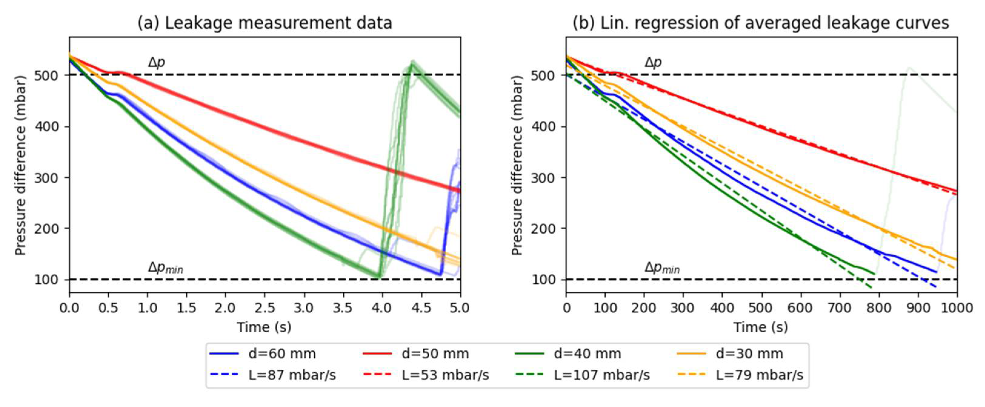
Figure 7a show the pressure difference profiles for all scheduled variations of normal force and surface roughness. The 10 repetitions for each respective setting were packed into one averaged profile. The influence of normal force and surface roughness may be present, but is significantly smaller than the influence of the gripper diameter. Therefore, all test runs for each gripper diameter were packed into one representative averaged pressure difference profile (Figure 7b). For simplification, a linear regression was applied to these profiles to determine the leakage rate for the four different grippers in combination with the attached dead volume.
Normally, it would be plausible if a larger gripper diameter would correlate with a higher leakage rate, according to [18]. The fact that the experimental results obtained in this work do not show this behavior may potentially be accounted to differences in the material batches utilized in gripper production. In [18] it is shown, that a linear relation exists between leakage rate L and dead volume V. Therefore, the measured leakage that has been determined for a fixed dead volume of V = 85 cm3 can be directly calculated for different dead volumes. For an arbitrary gripping system with N vacuum grippers, the resulting total dead volume V divided by N can be associated with each gripper. At the beginning of every process, the dead volume is initially evacuated in order to create the desired pressure difference Δ p = p a p e ( p a = atmospheric pressure, p e = target pressure). The required evacuation time t E with an ejector that supplies a suction flow S can be computed by Equation (4). With the air consumption of the ejector CEJ, the resulting compressed air use for evacuation CE can be calculated by Equation (5):
t E = V ln p a p e 1.3 S  
C E = t C E J  
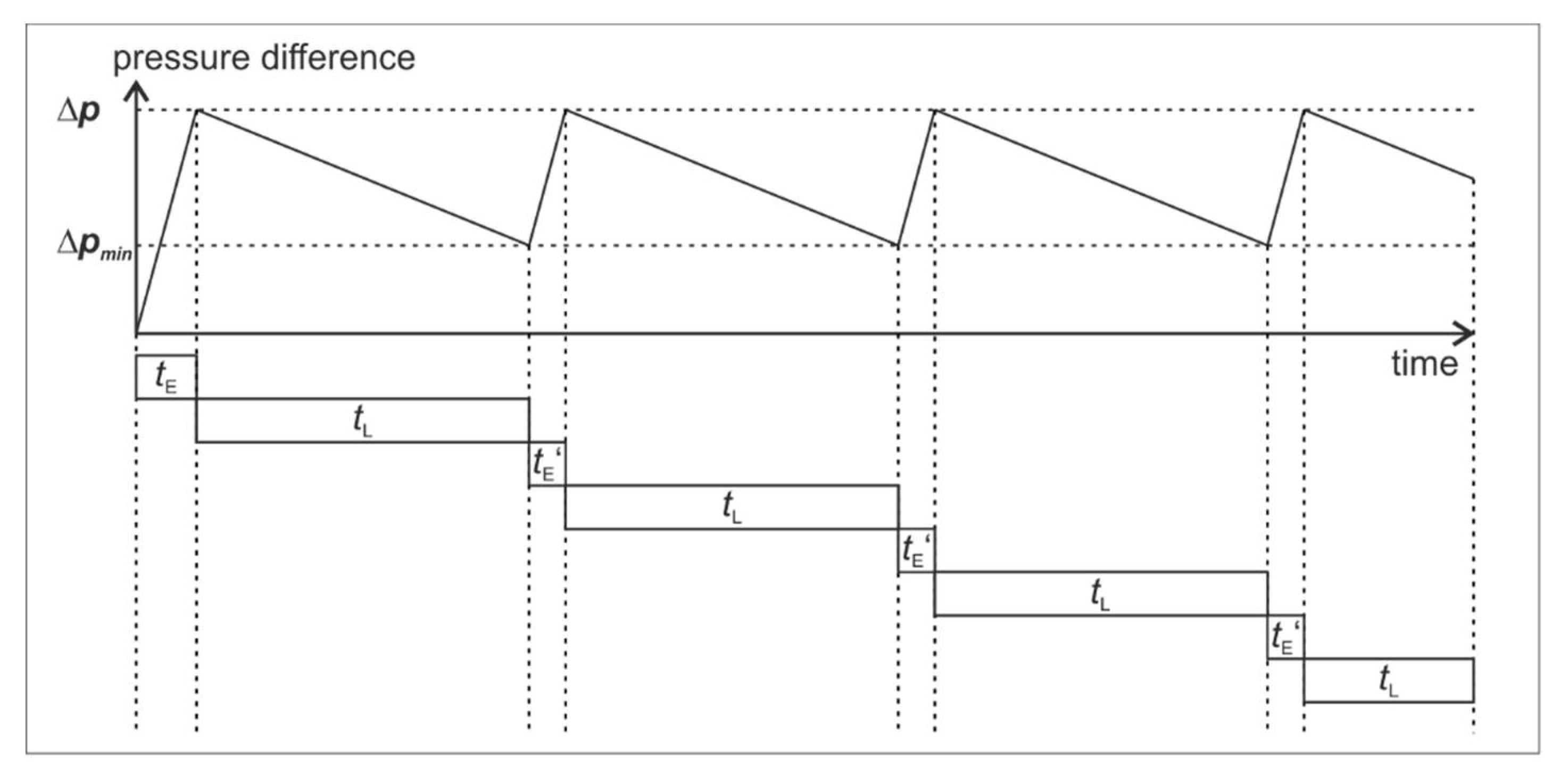
During the process, leakage causes a decrease of the pressure difference. Within a time interval of t, the pressure difference drops by Δ p D = t L L from Δ p to the minimally allowed pressure difference Δ p m i n (Figure 8). Depending on the allowed lower limit for the pressure difference Δ p m i n , the ejector is operated for a duration of t E in order to increase the pressure difference again up to Δ p .
Hence, the duration of the entire process t P is composed of the initial evacuation and multiple phases of leakage and re-evacuation, in the following (Equation (6)):
t P = t E + t L x + y + t E x + z  
Firstly, it is determined how many complete cycles of leakage and re-evacuation are performed during the process. The remaining time interval Δ t is computed in Equation (7):
Δ t = t P t L   m o d   t L + t E  
Two different cases are possible. If the remainder is less than t L , as shown in Figure 8, Equation (8) can be used to determine the parameters x, y and z in Equation (6). Otherwise, Equation (9) can be applied:
if   Δ t < t L :   x = f l o o r t P t E t L + t E ,     y = t P t E t L x t E x t L ,     z = 0
else :   x = f l o o r t P t E t L + t E ,     y = 1 ,     z = t P t E t L x + y t E x t E
The required amount of compressed air for the entire process C is composed of the air used for the initial evacuation CE and for leakage-induced re-evacuation CR during the process of duration t. The used ejector supplies a suction flow S at an air consumption of CEJ. Equation (10) provides the required amount of compressed air for the entire process C:
C = C E + C R = C E J V ln P a P a Δ p 1.3 S + x + z V ln P a Δ p m i n   P a Δ p 1.3 S
By this calculation scheme, depending on the specific leakage rate, the exact air consumption of arbitrarily configured gripping systems can be predicted with regard to a given process duration and the defined pressure difference values. Since the gripping system parameters are varied regardless of compressed air generation, in the proposed method, potential energy savings are approximated by the achieved savings in compressed air consumption.

2.4. Combined Method for Grasp Optimization and Gripping System Dimensioning

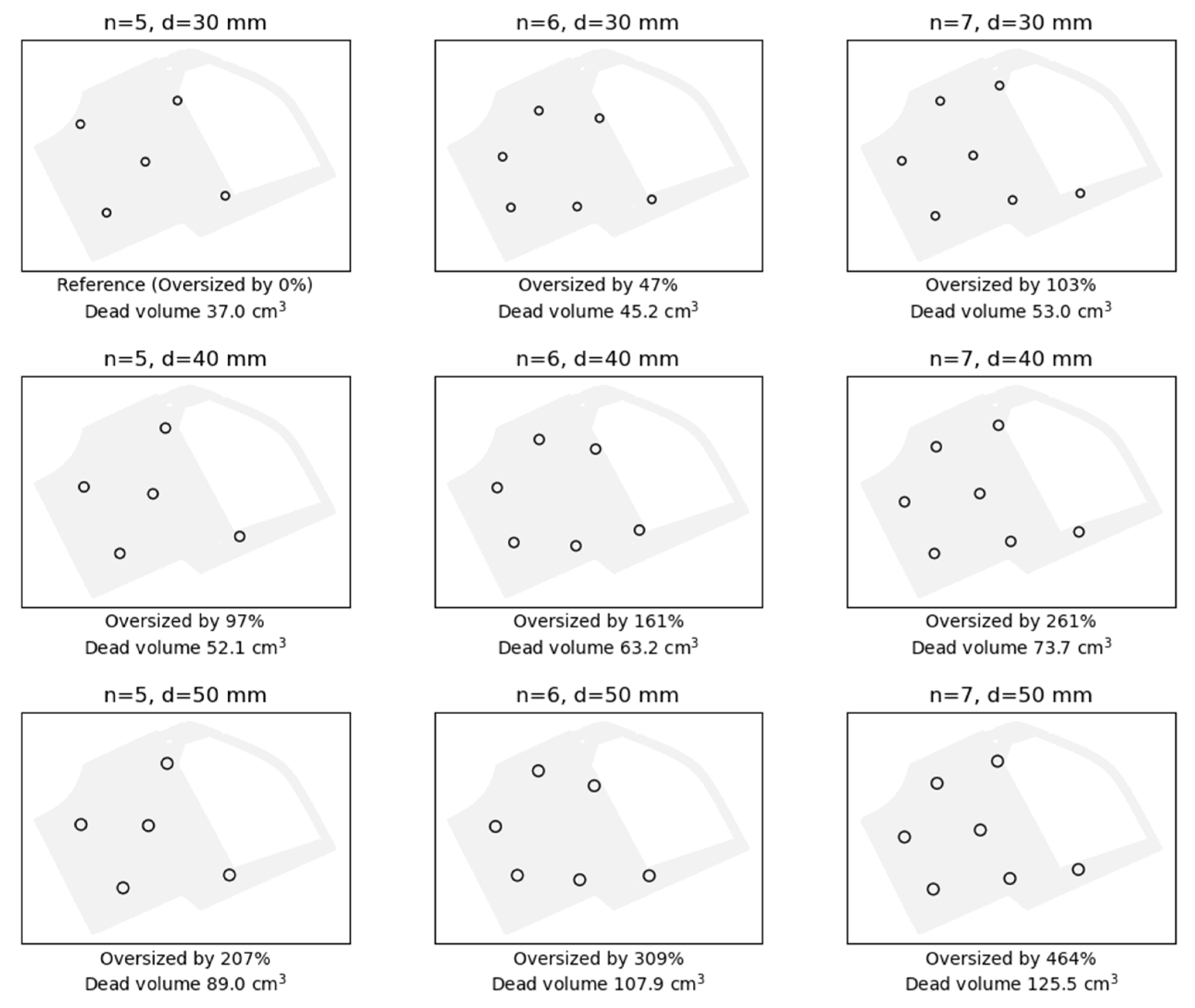
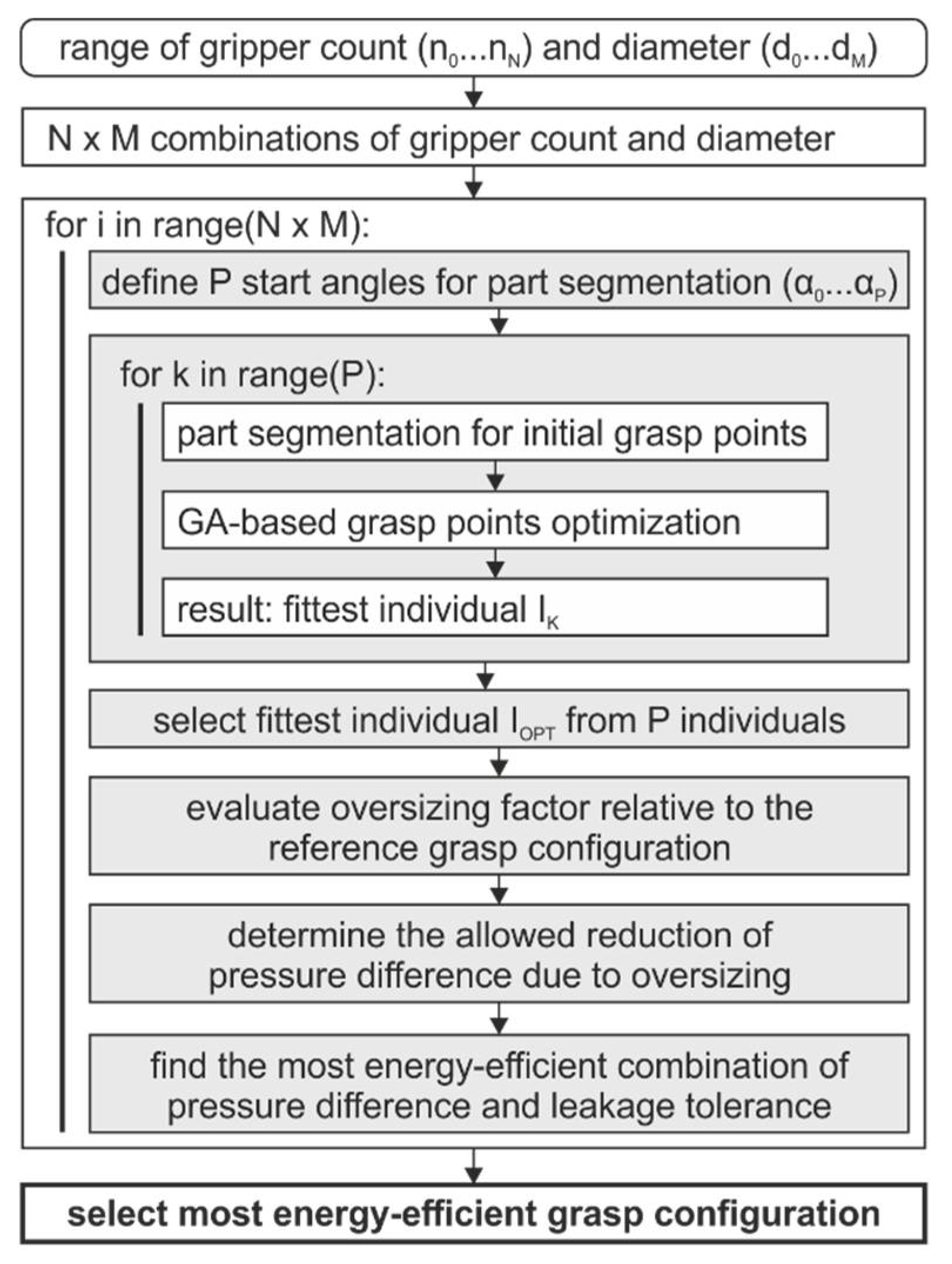
Based on the findings obtained in the above described investigations, the combined method for grasp optimization and gripping system dimensioning can be composed (Figure 9). First, as alternatives to the reference grasp configuration with n0 grippers of diameter d0, a range of different values for the gripper count n and the diameter d is defined. For each of the resulting Nx
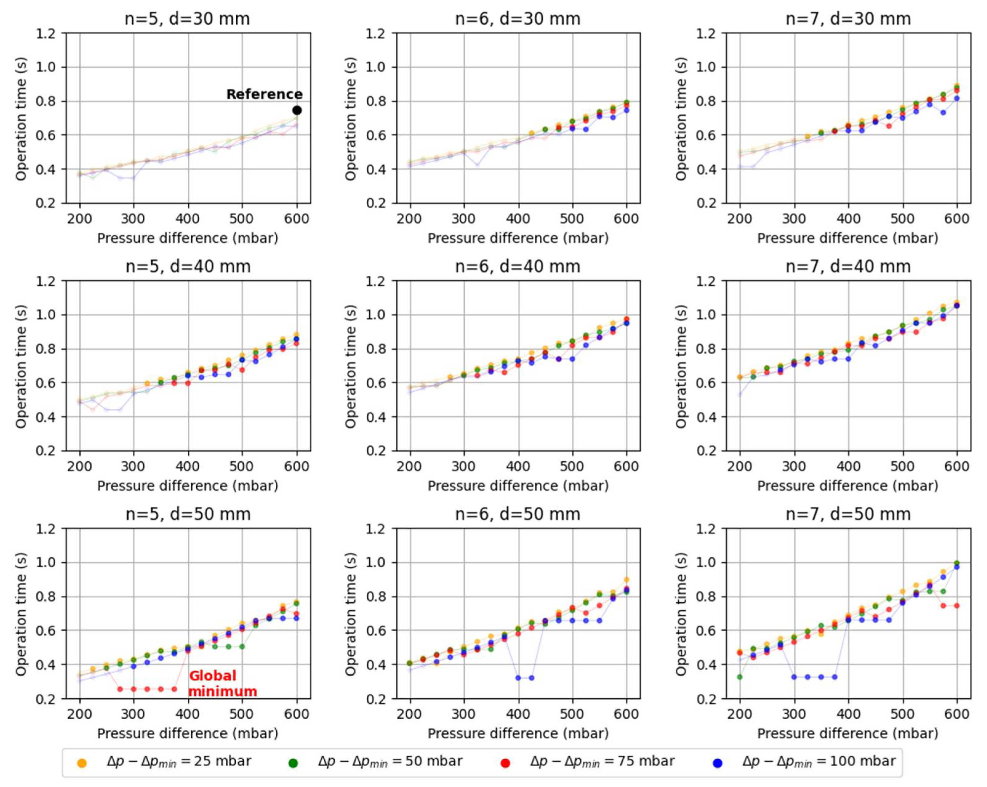
M combinations, the grasp optimization is conducted. Subsequent to the grasp optimization, for each grasp configuration it is evaluated to what extent it is oversized relative to the reference grasp configurations. For example, if the gripper count is doubled relative to the reference configuration, the oversizing factor is 2. Hence, the target pressure difference could potentially be reduced to the half, since this would yield the same holding force. In combination with the target pressure difference, the leakage tolerance (i.e., the allowed drop in pressure difference, before the ejectors is operated again in order to reach the initially targeted pressure difference) can also be adjusted within the allowed range that is limited by the oversizing factor. By means of the gripper-specific leakage information and the calculation scheme for determining the air consumption depending on pressure difference Δ p and leakage tolerance Δ p Δ p m i n , the resulting energy use can be predicted in the relevant value range for Δ p and Δ p m i n . Finally, the most efficient set of gripper count, gripper diameter, target pressure difference and minimum pressure difference [n, d, Δ p , Δ p m i n ] is selected.

3. Results

As an industrially relevant use case, a car door 3D scanned with a GOM ATOS Triple Scan system (GOM GmbH, Braunschweig, Germany) is used as an example to demonstrate the introduced method for grasp optimization and gripping system dimensioning. This part has a large surface area compared to its thickness (<1 mm) and can therefore be simplified to a 2D polygon. Starting from the reference configuration (n = 3, d = 30 mm), eight further variants were created by full-factorial combination of [n0, n1, n2] = [3, 4, 5] and [d0, d1, d2] = [30 mm, 40 mm, 50 mm]. Hence, all additional configurations are oversized to a certain degree relative to the reference configuration. Figure 10 shows the optimized grasp configurations and the resulting dead volumes. The dead volumes were calculated based on the assumption that all grippers are supplied with vacuum by a central vacuum distributor in the center of the part.
Since the additionally created grasp configurations are oversized relative to the reference, the target pressure difference Δ p in combination with the leakage tolerance Δ p Δ p m i n can be reduced accordingly. As an example, in the case of n = 6 and d = 30 mm, the optimized grasp configuration is oversized by 47% in comparison to the reference. Hence, the minimal pressure difference that is allowed to occur due to leakage is about half of the reference pressure difference (600 mbar). The possible combinations of pressure difference and leakage tolerance are depicted in in Figure 11 where critical parameter combinations to be neglected are transparent. Due to the gripper-specific leakage properties, the grasp configuration n = 6 and d = 50 mm yields the largest achievable energy saving, i.e., a reduction of ejector operation time by 67% from initially 0.76 s (reference, n = 6 and d = 30 mm) to 0.25 s. Obviously, this approach is only feasible for cases where a larger gripper diameter than initially selected can actually be properly positioned on the part.

4. Discussion

The findings of this work show that practical knowledge about the gripper-object-specific holding force and leakage rate enables significant energy savings that can be achieved by targeted optimization of grasp points and the gripping system dimensions as well as the corresponding ejector operating parameters. Firstly, with regard to the presented grasp optimization algorithm it can be stated that by use of experimentally obtained information about the maximum holding force that can be achieved by certain vacuum grippers in combination with a specific object geometry, the position of each gripper can be adjusted in a targeted way. A constrained genetic algorithm ensures that variations of the respective gripper positions are confined in order to limit additional inertial forces at the gripper-object-interface. The gripper-object-specific information about maximally achievable holding forces was only obtained for gripper of diameter 60 mm and assumed to be analogue for smaller diameters, in the scope of this work. Hence, the influence of the gripper size in combination with different object geometries, thus the changed form adaptability, is one field to be further examined in the future. The leakage rate measurements were conducted with regard to roughness values within a range that is most relevant to fields such as handling sheet metal in a press shop. An extension of the roughness range would be required if the proposed gripping system dimensioning method should be applied to other applications of automated handling of sheet parts with rough surfaces. However, at some point it is questionable if the roughness-induces leakage may become so high that it is not feasible anymore to use the air saving function of the ejector, where the suction flow is deliberately stopped during the handling process.
Future research could investigate the application of different ejector types that mainly differ in suction performance and therefore in compressed air consumption. This adds another dimension to the system dimensioning optimization problem, but can potentially enable further energy savings. From industrial perspective, the obtained findings could be implemented in a configuration tool, where experimentally obtained data about gripper-object- and gripper-roughness-specific data are stored in a database, that can quickly design the application- and hence customer-specific gripping system solution with the benefit of minimal energy consumption.

Author Contributions

Conceptualization: F.G. and S.B.; Methodology: F.G.; Software: F.G. and S.B.; Formal analysis: M.R. and K.D.; Investigation: F.G. and S.B.; Resources: K.D.; Data Curation: F.G.; Writing—original draft preparation: F.G.; Writing—review and editing: M.R. and K.D.; Visualization: F.G.; Project Administration: F.G. and K.D.; Funding acquisition: F.G. and K.D. All authors have read and agreed to the published version of the manuscript.

Funding

This research was funded by the German Federal Ministry of Economic Affairs and Energy, grant number 03ET1559B.
Machines 09 00149 i001

Institutional Review Board Statement

Not applicable.

Informed Consent Statement

Not applicable.

Data Availability Statement

Data sharing not applicable.

Acknowledgments

The authors thank Harald Kuolt at J. Schmalz GmbH for his support.

Conflicts of Interest

The authors declare no conflict of interest.

References

  1. Tai, K.; El-Sayed, A.-R.; Shahriari, M.; Biglarbegian, M.; Mahmud, S. State of the Art Robotic Grippers and Applications. Robotics 2016, 5, 11. [Google Scholar] [CrossRef] [Green Version]
  2. International Federation of Robotics. World Robotics Report 2018; VDMA Verlag: Frankfurt, Germany, 2018; ISBN 978-3-8163-0725-9. [Google Scholar]
  3. Gabriel, F.; Fahning, M.; Meiners, J.; Dietrich, F.; Dröder, K. Modeling of vacuum grippers for the design of energy efficient vacuum-based handling processes. Prod. Eng. Res. Dev. 2020, 14. [Google Scholar] [CrossRef]
  4. Kuolt, H.; Kampowski, T.; Poppinga, S.; Speck, T.; Moosavi, A.; Tautenhahn, R.; Weber, J.; Gabriel, F.; Pierri, E.; Dröder, K. Increase of energy efficiency in vacuum handling systems based on biomimetic principles. In Proceedings of the 12th International Fluid Power Conference (12. IFK), Dresden, Germany, 12–14 October 2020; Weber, J., Ed.; Technische Universität Dresden: Dresden, Germany, 2020. [Google Scholar]
  5. Gabriel, F.; Bobka, P.; Dröder, K. Model-Based Design of Energy-Efficient Vacuum-Based Handling Processes. Procedia CIRP 2020, 93, 538–543. [Google Scholar] [CrossRef]
  6. Gabriel, F.; Römer, M.; Bobka, P.; Dröder, K. Model-based grasp planning for energy-efficient vacuum-based handling. CIRP Ann. 2021, 1–4. [Google Scholar] [CrossRef]
  7. Mahler, J.; Matl, M.; Liu, X.; Li, A.; Gealy, D.; Goldberg, K. Dex-Net 3.0: Computing Robust Vacuum Suction Grasp Targets in Point Clouds Using a New Analytic Model and Deep Learning. In Proceedings of the 2018 IEEE International Conference on Robotics and Automation (ICRA), Brisbane, Australia, 21–26 May 2018; IEEE: New York City, NY, USA, 2018; pp. 1–8, ISBN 978-1-5386-3081-5. [Google Scholar]
  8. Wan, W.; Harada, K.; Kanehiro, F. Planning Grasps for Assembly Tasks. 2019. Available online: http://arxiv.org/pdf/1903.01631v1 (accessed on 10 December 2020).
  9. Jørgensen, T.B.; Hansen, B.R.; Pedersen, M.M.; Krüger, N.; Hansen, N.W. A Flexible Suction Based Grasp Tool and Associated Grasp Strategies for Handling Meat. In Proceedings of the 2018 4th International Conference on Mechatronics and Robotics Engineering—ICMRE 2018, Valenciennes, France, 7–11 February 2018; ACM Press: New York, NY, USA, 2018; pp. 43–47, ISBN 9781450363655. [Google Scholar]
  10. Valencia, A.J.; Idrovo, R.M.; Sappa, A.D.; Guingla, D.P.; Ochoa, D. A 3D vision based approach for optimal grasp of vacuum grippers. In Proceedings of the 2017 IEEE International Workshop of Electronics, Control, Measurement, Signals and their Application to Mechatronics (ECMSM), Donostia-San Sebastian, Spain, 24–26 May 2017; IEEE: New York City, NY, USA, 2017; pp. 1–6, ISBN 978-1-5090-5582-1. [Google Scholar]
  11. You, F.; Mende, M.; Stogl, D.; Hein, B.; Kroger, T. Model-Free Grasp Planning for Configurable Vacuum Grippers. In Proceedings of the 2018 IEEE/RSJ International Conference on Intelligent Robots and Systems (IROS), Madrid, Spain, 1–5 October 2018; IEEE: New York City, NY, USA, 2018; pp. 4554–4561, ISBN 978-1-5386-8094-0. [Google Scholar]
  12. Sdahl, M.; Kuhlenkötter, B. CAGD—Computer Aided Gripper Design for a Flexible Gripping System. Int. J. Adv. Robot. Syst. 2005, 2. [Google Scholar] [CrossRef]
  13. Schmalz, J.; Giering, L.; Hölzle, M.; Huber, N.; Reinhart, G. Method for the Automated Dimensioning of Gripper Systems. Procedia CIRP 2016, 44, 239–244. [Google Scholar] [CrossRef] [Green Version]
  14. Liu, C.-H.; Chiu, C.-H.; Hsu, M.-C.; Chen, Y.; Chiang, Y.-P. Topology and Size–Shape Optimization of an Adaptive Compliant Gripper with High Mechanical Advantage for Grasping Irregular Objects. Robotica 2019, 37, 1383–1400. [Google Scholar] [CrossRef]
  15. Yao, S.; Ceccarelli, M.; Carbone, G.; Dong, Z. Grasp configuration planning for a low-cost and easy-operation underactuated three-fingered robot hand. Mech. Mach. Theory 2018, 129, 51–69. [Google Scholar] [CrossRef]
  16. Kamadan, A.; Kiziltas, G.; Patoglu, V. A Systematic Design Selection Methodology for System-Optimal Compliant Actuation. Robotica 2019, 37, 656–674. [Google Scholar] [CrossRef]
  17. Straub, D. Design method for temporarily energy self-sufficient vacuum gripping systems. Procedia CIRP 2019, 84, 593–598. [Google Scholar] [CrossRef]
  18. Straub, D. Behavior and impact of leakage in vacuum gripping systems. In Proceedings of the 12th International Fluid Power Conference (12. IFK), Dresden, Germany, 12–14 October 2020; Weber, J., Ed.; Dresdner Verein zur Förderung der Fluidtechnik e. V. Dresden: Dresden, Germany, 2020; pp. 27–34. [Google Scholar]
  19. Schaffrath, R.; Jäger, E.; Winkler, G.; Doant, J.; Todtermuschke, M. Vacuum gripper without central compressed air supply. Procedia CIRP 2021, 97, 76–80. [Google Scholar] [CrossRef]
  20. Nakamoto, H.; Ohtake, M.; Komoda, K.; Sugahara, A.; Ogawa, A. A Gripper System for Robustly Picking Various Objects Placed Densely by Suction and Pinching. In Proceedings of the 2018 IEEE/RSJ International Conference on Intelligent Robots and Systems (IROS), Madrid, Spain, 1–5 October 2018; IEEE: New York City, NY, USA, 2018; pp. 6093–6098, ISBN 978-1-5386-8094-0. [Google Scholar]
  21. Hartsuijker, C.; Welleman, J.W. Engineering Mechanics: Equilibrium; Springer: Dordrecht, The Netherlands, 2006; Volume 1, ISBN 978-1-4020-5483-9. [Google Scholar]
  22. Steinhilper, W.; Sauer, B. Konstruktionselemente des Maschinenbaus 1; Springer: Berlin/Heidelberg, Germany, 2012. [Google Scholar]
  23. DIN Deutsches Institut für Normung e. V. Testing of Rubber: Determination of Tensile Strength at Break, Tensile Stress at Yield, Elongation at Break and Stress Values in a Tensile Test, DIN 53504:2017-03; Beuth Verlag GmbH: Berlin, Germany, 2017. [Google Scholar]
Figure 1. A high electrical energy input is required related to the output of useable energy for vacuum-based handling [3].
Machines 09 00149 g001
Figure 2. Combined grasp optimization and system dimensioning method. Reprinted with permission from ref. [6]. Copyright 2021 Elsevier.
Machines 09 00149 g002
Figure 3. The Distance Criterion can be derived by application of Virtual Work.
Machines 09 00149 g003
Figure 4. The specific combination of gripper and object geometry has a significant influence on the achievable holding force [3].
Machines 09 00149 g004
Figure 5. (a) Experimental setup [3]; (b) Parametrized test objects for investigation of roughness-dependent maximum holding force.
Machines 09 00149 g005
Figure 6. The results of the roughness variation experiments indicate that the influence of the roughness on the maximum holding force can be neglected.
Machines 09 00149 g006
Figure 7. Results of leakage measurements. (a) Measured pressure difference for all scheduled variations of normal force and surface roughness (mean average of sets of 10 repetitions); (b) Linear regression of pressure difference curves averaged over all variations.
Machines 09 00149 g007
Figure 8. Exemplary pressure difference profile comprising the initial evacuation as well as repeating drops in pressure difference and re-evacuation.
Machines 09 00149 g008
Figure 9. Flow chart of the combined method for grasp optimization and gripping system dimensioning.
Machines 09 00149 g009
Figure 10. The optimized grasp configurations for the regarded combinations of gripper count n and gripper diameter d result in different degrees of oversizing.
Machines 09 00149 g010
Figure 11. Depending on the degree of oversizing, the reduction of target and minimum pressure difference within the allowed range yields significant energy savings. The non-permissible values for pressure difference and leakage are transparent.
Machines 09 00149 g011
Table 1. Measured mean roughness values of the fabricated test objects.
Range 1Range 2Range 3Range 4
MaterialAluminum (blank)PA6 (sanded)Steel (sanded)Aluminum (sanded)
Measured RZ (µm)0.4 ± 0.17.0 ± 1.511.0 ± 1.016.5 ± 0.1
Range RZ (µm)0–44–99–1414–18
Publisher’s Note: MDPI stays neutral with regard to jurisdictional claims in published maps and institutional affiliations.

