
Investigation of Characteristics of a Novel Torque Motor Based on an Annulus Air Gap


Abstract
:1. Introduction
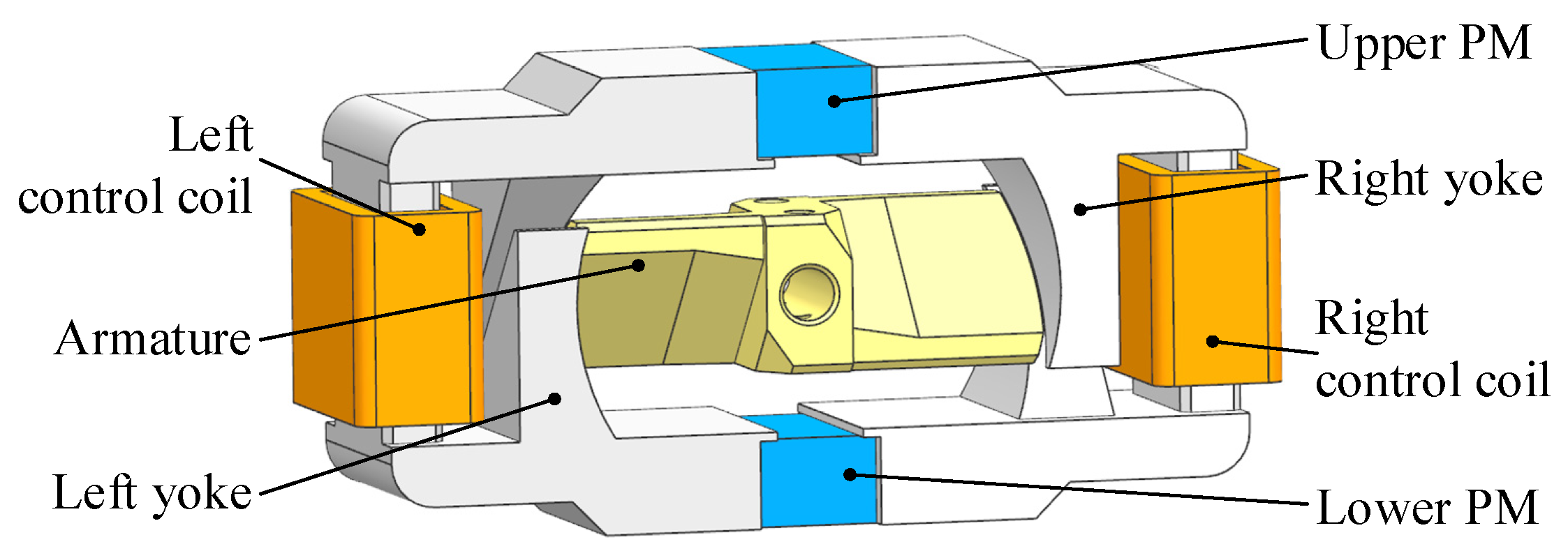
2. Structure and Working Principle
3. Analytical Modeling
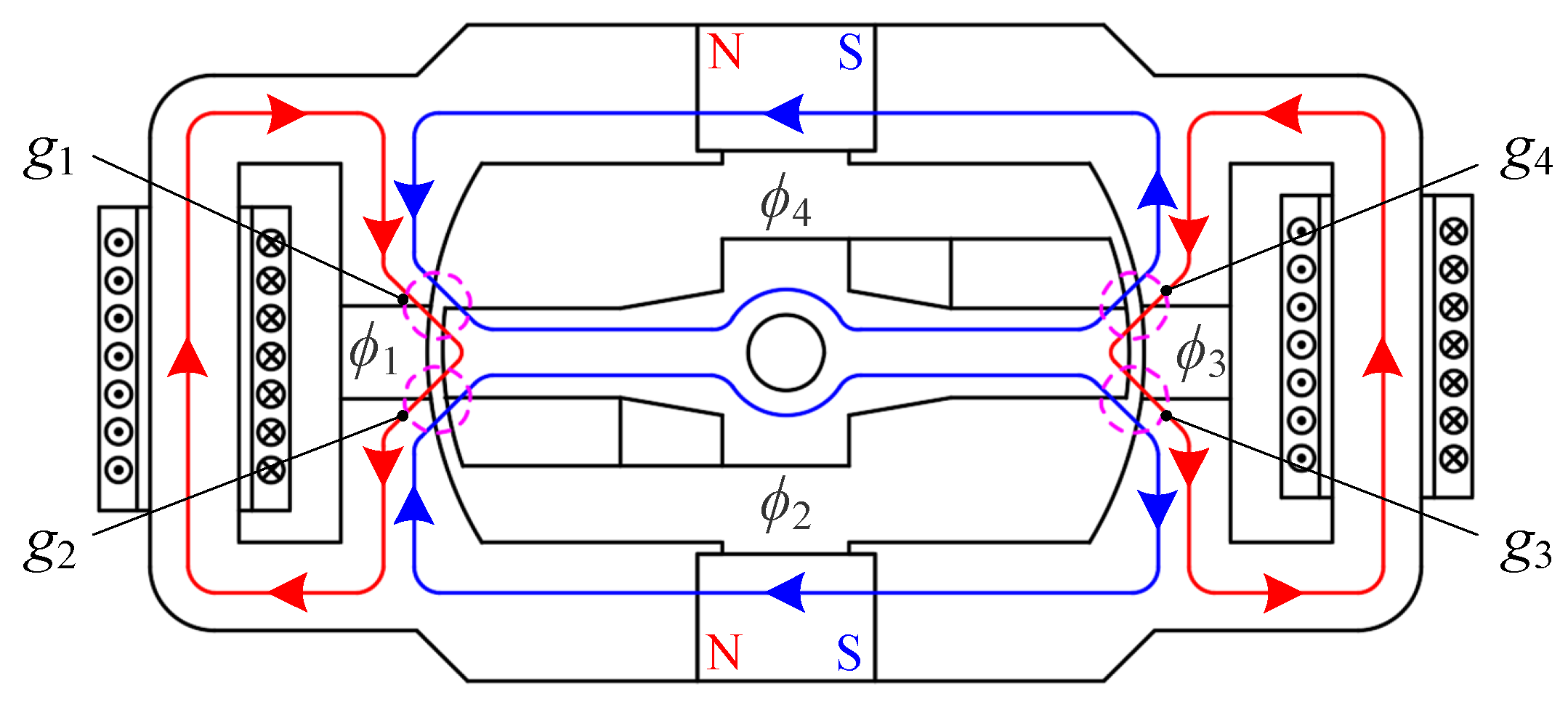
3.1. Air Gap Analysis
3.2. Magnetic Circuit and Torque Analysis
4. Parameter Optimization
5. Experiment
6. Conclusions
- (1)
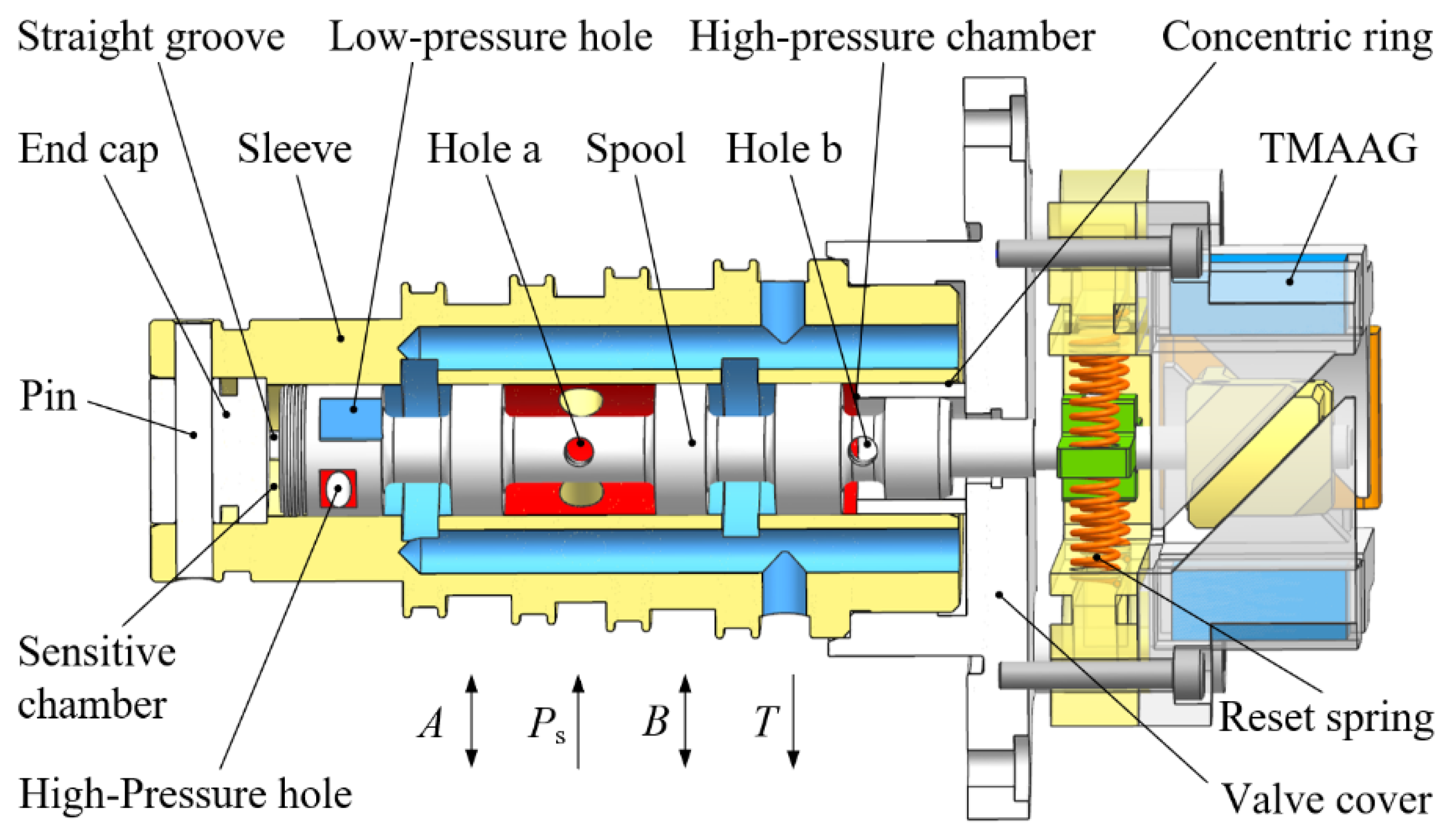
- In order to reduce machining difficulty and costs of 2D valves, a novel TMAAG is proposed in this paper, which has a negative feedback mechanism to replace the original spiral groove of traditional 2D valves.
- (2)
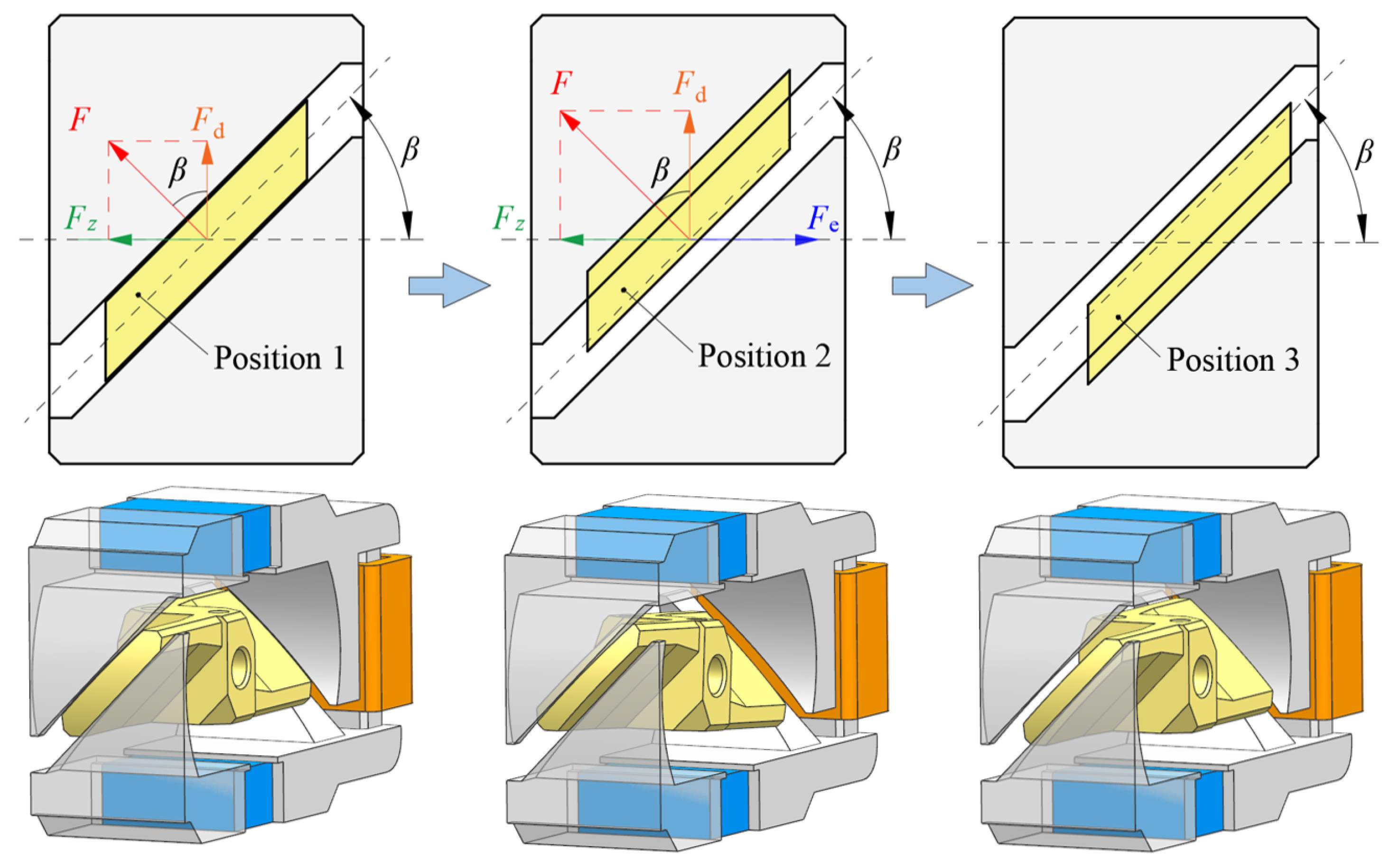
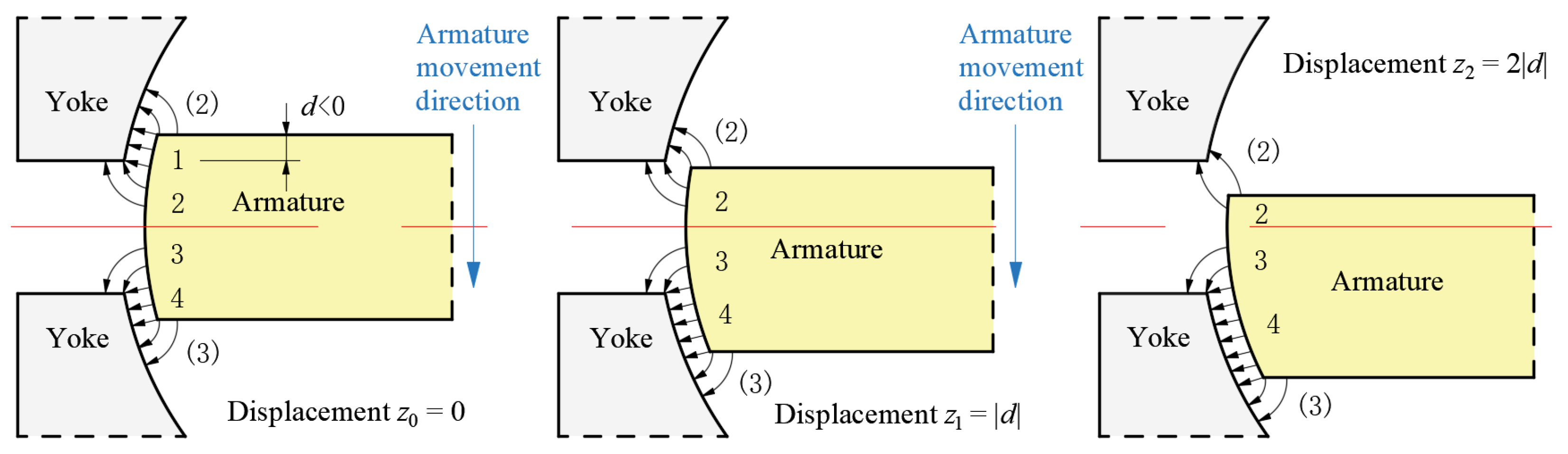
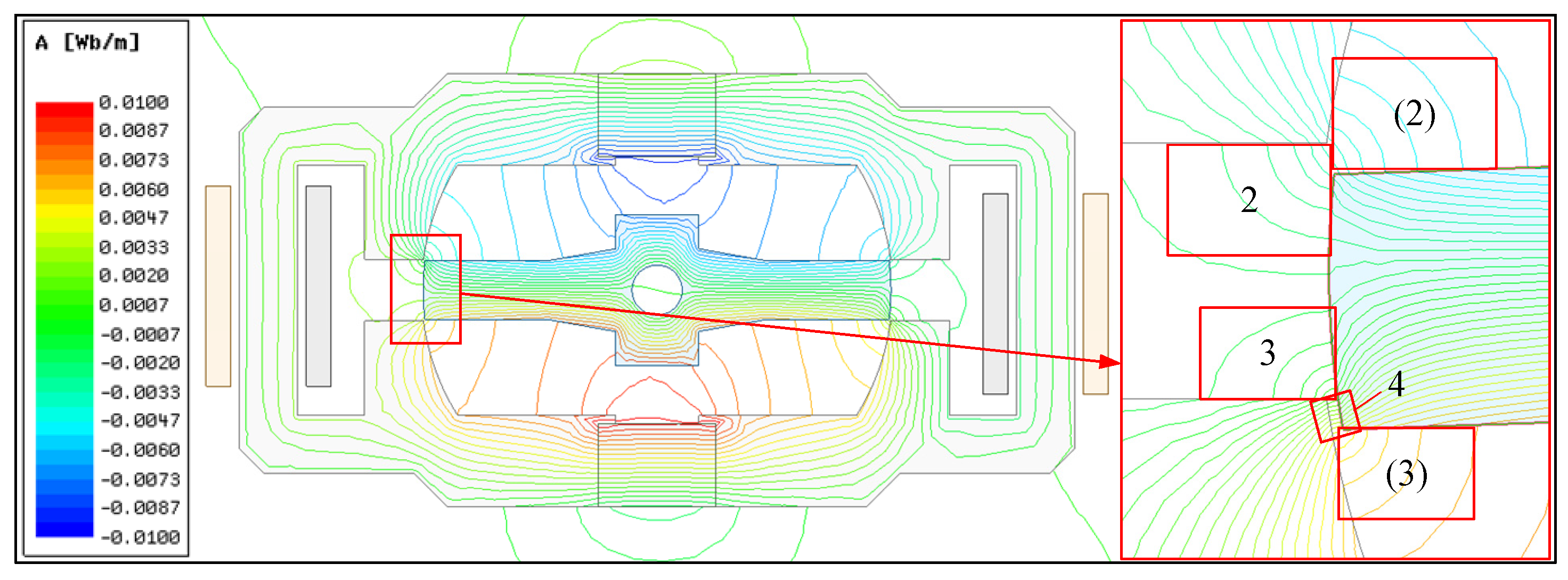
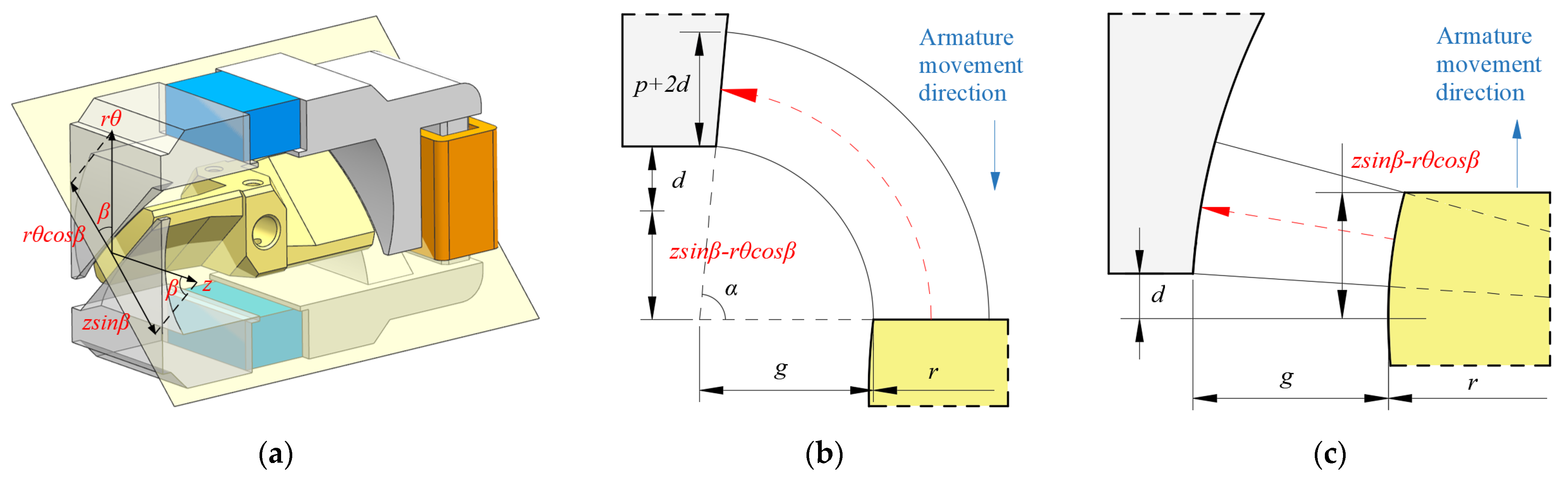
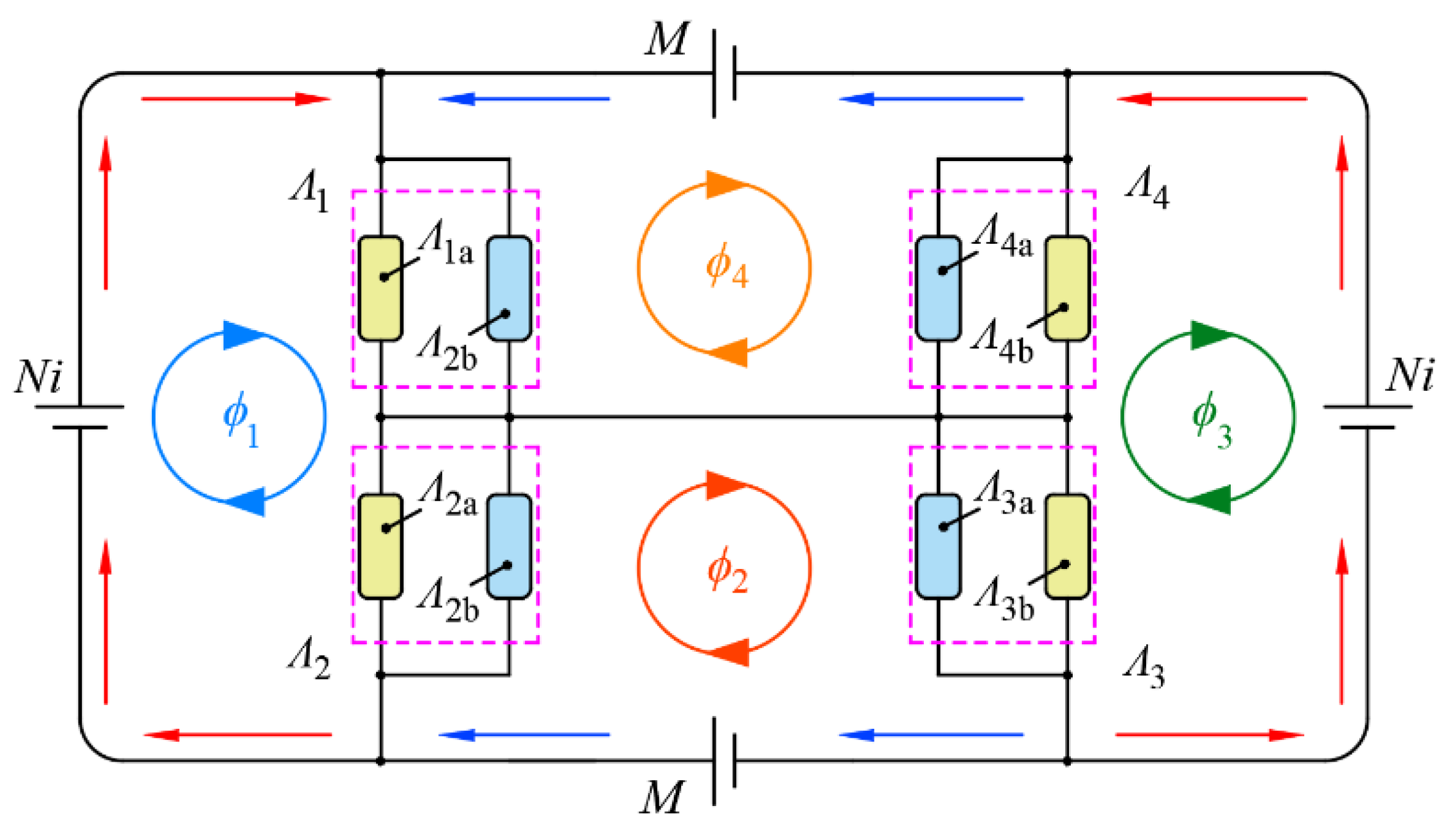
- Aiming at the annulus air gap structure of TMAAG, the air gap change law is analyzed and verified by FEM simulation. A qualitative analytical model that can intuitively reflect the torque change law of TMAAG is proposed, which shows that the output torque consists of three parts: electromagnetic torque, driving torque, and feedback torque.
- (3)
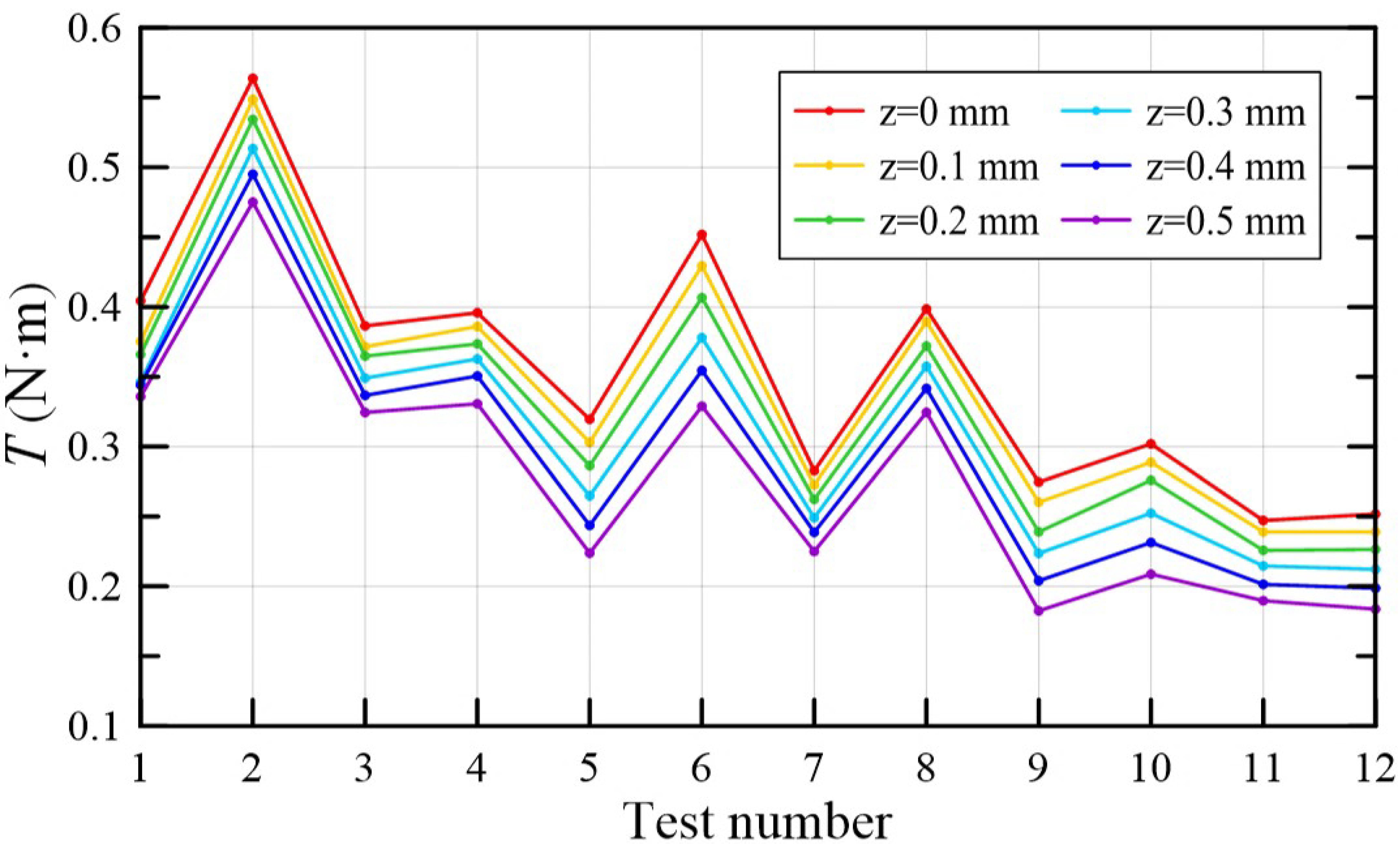
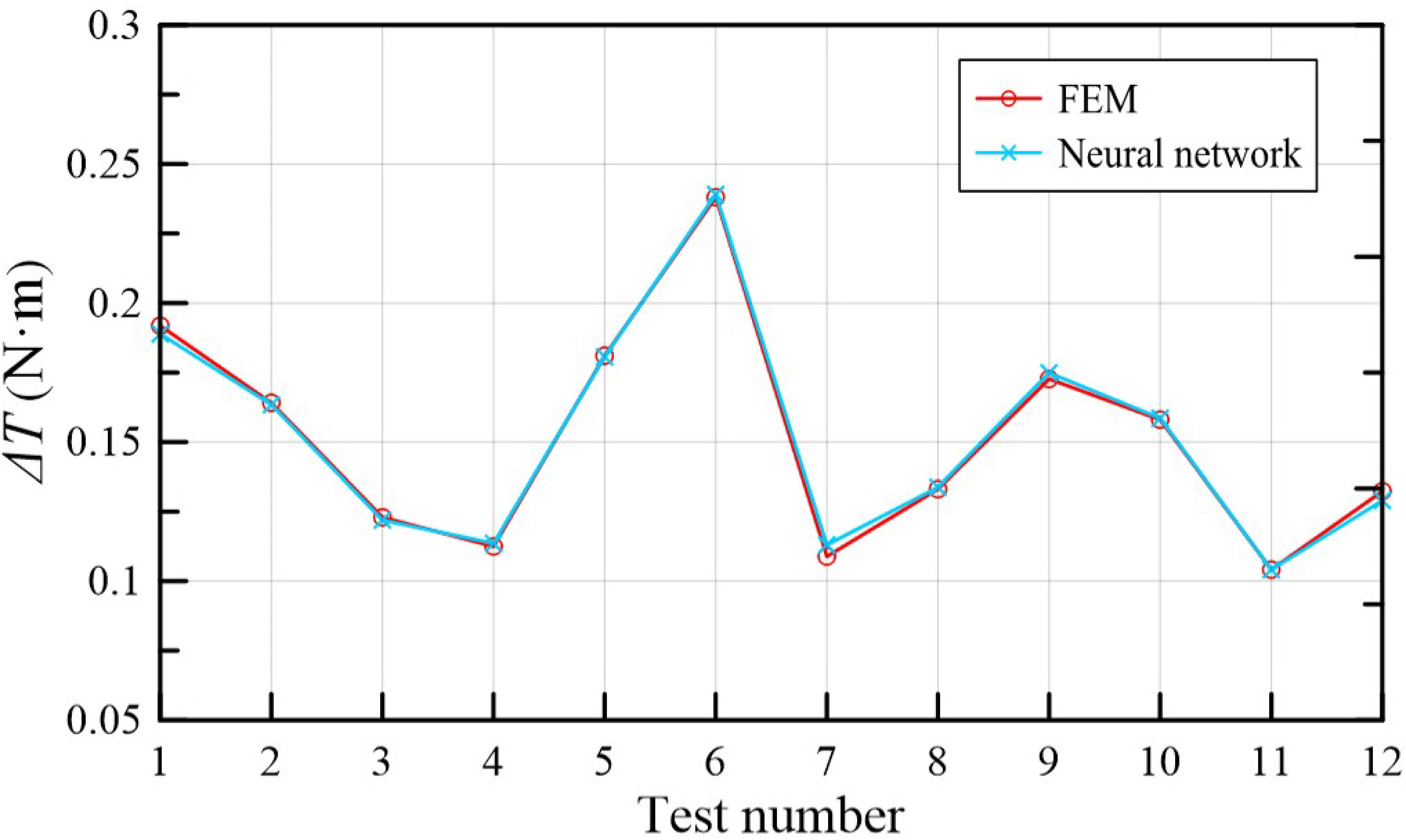
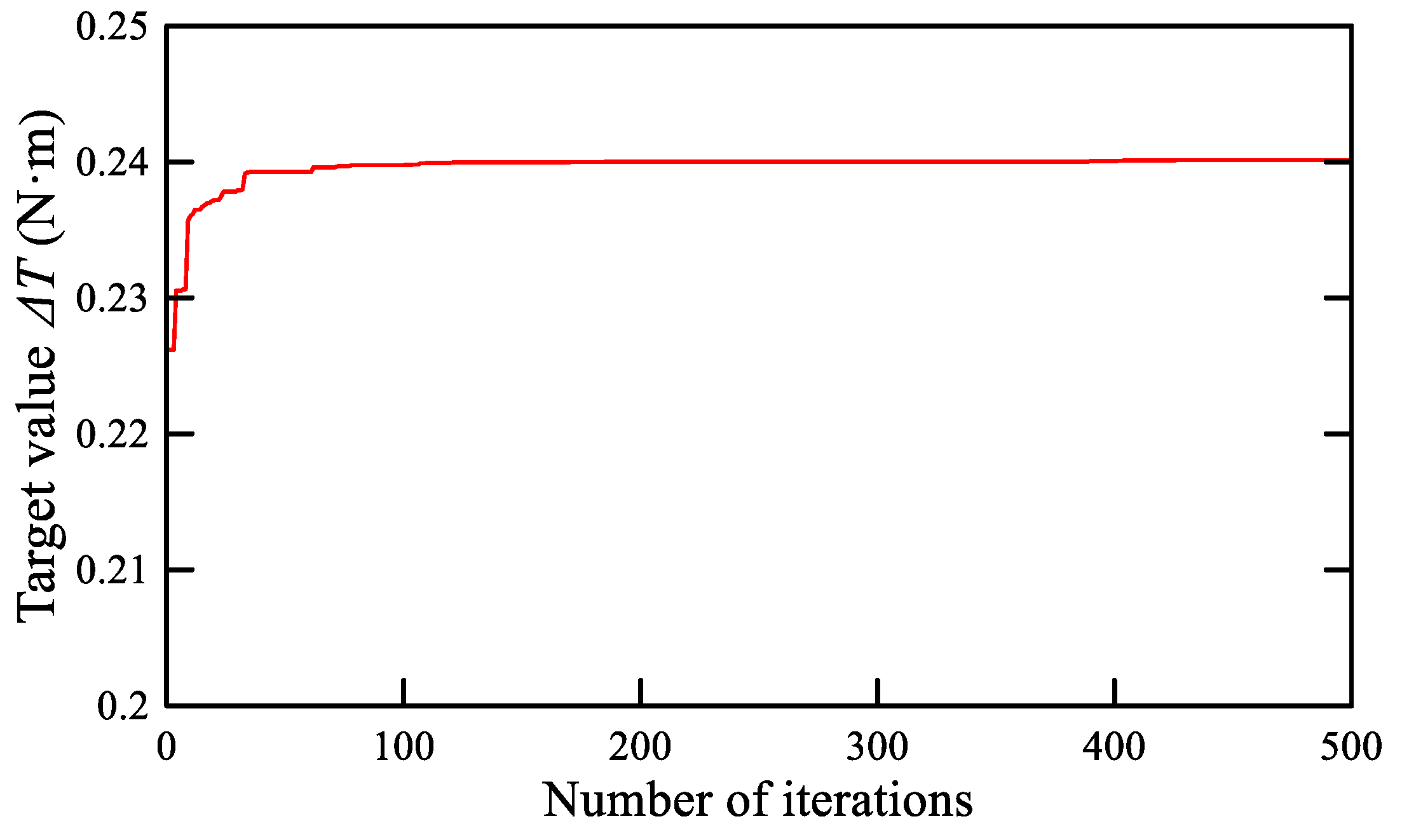
- Using the method of orthogonal test, the significance of the factors affecting the torque change was analyzed, and the optimization results were obtained through neural network learning and genetic algorithm verification.
- (4)
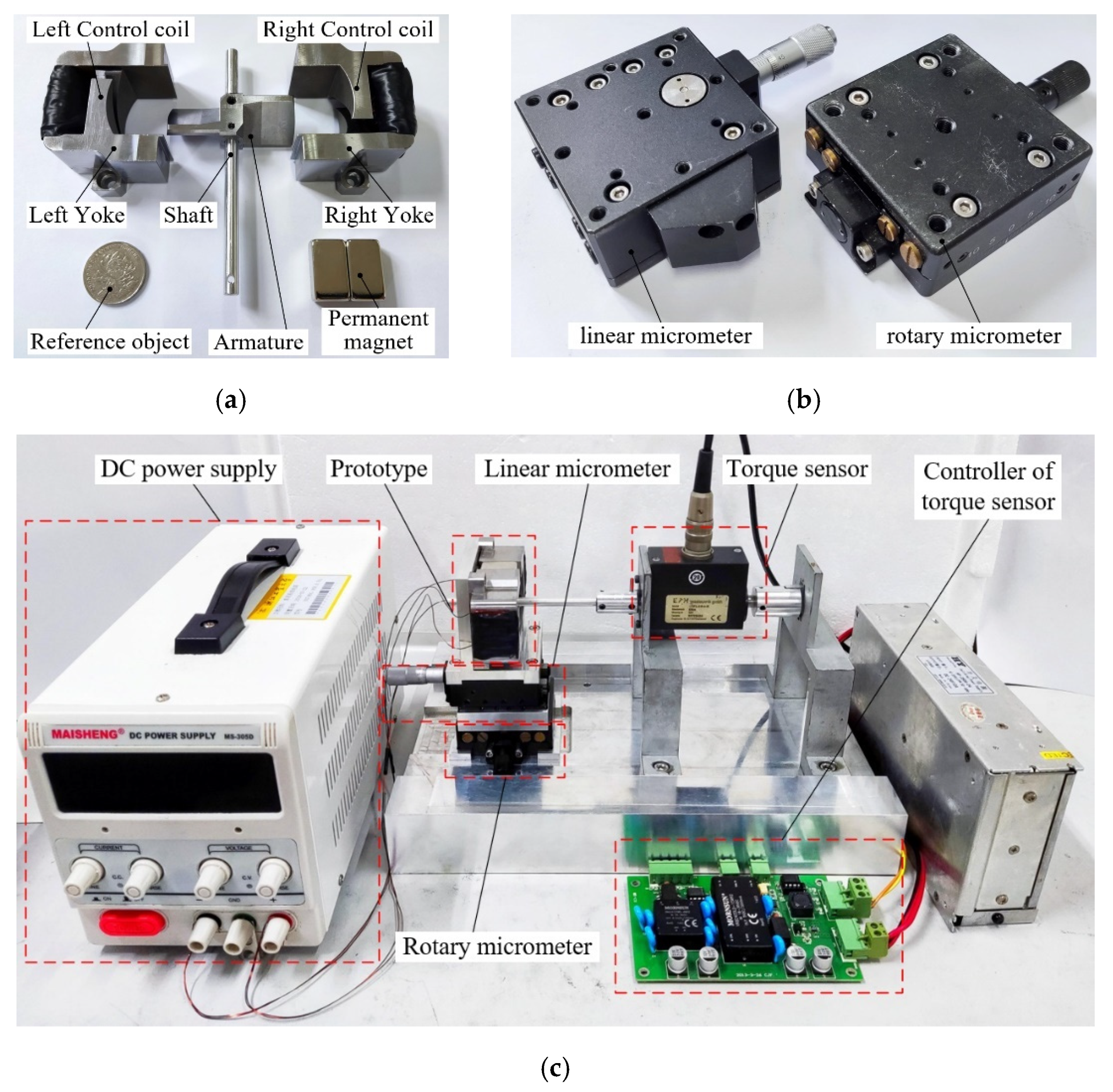
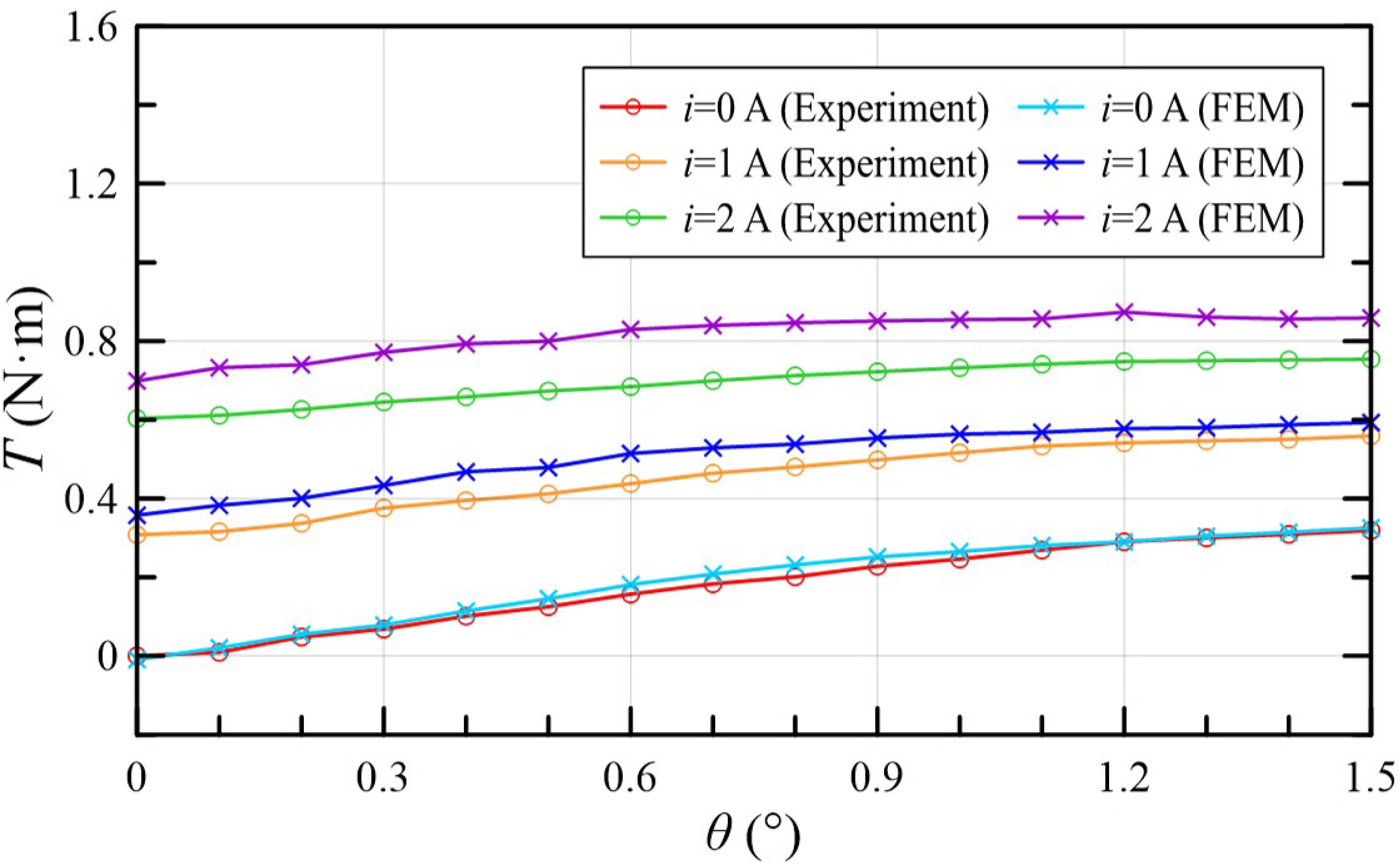
- A prototype of TMAAG was machined, and the experiment proved the consistency of the analytical analysis and experiment. For torque-angle characteristics, the output torque increased with increasing current and rotary angle, which reached about 0.754 N·m with 2 A and 1.5°. While for torque-displacement characteristics, due to the negative feedback mechanism, the output torque decreased with armature displacement, which was about 0.084 N·m with 2 A and 1 mm. The research validates the unique negative feedback mechanism of the TMAAG and indicates that it can be potentially used as an electro-mechanical converter of 2D valves.
- (5)
- In order to improve the optimization effect, more factors and levels in orthogonal tests will be considered in future work. A robust design optimization based on space reduction strategy might be used for the optimization algorithm.
Author Contributions
Funding
Data Availability Statement
Conflicts of Interest
Nomenclature
| Pitch angle | |
| Air gap | |
| Magnetic flux | |
| Magnetic force | |
| Circumferential component force | |
| Driving torque | |
| Rotation angle | |
| Axial component force | |
| External force | |
| Feedback torque | |
| Axial displacement | |
| Opening between the yoke and the armature | |
| Permeance | |
| Permeability of the material | |
| Magnetic equipotential plane aera | |
| The path distance along the direction of the magnetic flux line | |
| Air gap permeance of magnetic strengthened side | |
| Air gap permeance of magnetic weakened side | |
| Permeability of air | |
| A parameter related to the width of the magnetic equipotential plane | |
| A parameter related to the ellipse cut by the cylinder along the pitch angle | |
| Armature radius | |
| Armature wing length | |
| Permanent magnet magnetic potential | |
| Coil turns | |
| Current | |
| Air gap magnetic potential | |
| Magnetic co-energy | |
| Output torque | |
| Electromagnetic torque coefficient | |
| Rotary magnetic spring stiffness | |
| Linear magnetic spring stiffness | |
| Torque change value every 0.1 mm |
References
- Yang, H.Y. Review of Intelligent Manufacturing and Intelligent Hydraulic Components. Chin. Hydraul. Pneum. 2020, 1, 1–9. [Google Scholar]
- Tamburrano, P.; Plummer, A.R.; Distaso, E.; Amirante, R. A review of electro-hydraulic servovalve research and development. Int. J. Fluid. Power. 2018, 1–23. [Google Scholar] [CrossRef]
- Tamburrano, P.; Plummer, A.R.; Distaso, E. A review of direct drive proportional electrohydraulic spool valves: Industrial state-of-the-art and research advancements. J. Dyn. Syst. Meas. Control 2019, 141, 020801. [Google Scholar] [CrossRef]
- Vyas, J.J.; Gopalsamy, B.; Joshi, H. Electro-Hydraulic Actuation Systems: Design, Testing, Identification and Validation; Springer: Singapore, 2018; ISBN 9789811325465. [Google Scholar]
- Huang, L.; Ji, H.; Zhu, Y. Analysis of effective working characteristic of the proportional solenoid. In Proceedings of the 2017 International Conference on Green Energy and Applications (ICGEA), Singapore, 11 May 2017; pp. 35–38. [Google Scholar]
- Meng, B.; Lai, Y.J.; Qiu, X.G. Regulation method for torque–angle characteristics of rotary electric–mechanical converter based on hybrid air gap. Chin. J. Mech. Eng. 2020, 33, 35. [Google Scholar] [CrossRef]
- Li, Y.; Ding, F.; Cui, J. Low power linear actuator for direct drive electrohydraulic valves. J. Zhejiang Univ. Sci. A 2008, 9, 940–943. [Google Scholar] [CrossRef]
- Direct Drive Servo Valves D633/D634. Available online: https://www.heash-tech.com/uploads/59ba1fb5e65b8717954917.pdf (accessed on 31 May 2021).
- Xu, B.; Shen, J.; Liu, S.H.; Zhang, J.H. Research and Development of Electro-hydraulic Control Valves Oriented to Industry 4.0: A Review. Chin. J. Mech. Eng. 2020, 33, 29. [Google Scholar] [CrossRef] [Green Version]
- Yin, Y.B. Electro Hydraulic Control Theory and Its Applications Under Extreme Environment; Butterworth-Heinemann: Oxford, UK, 2019. [Google Scholar]
- Amirante, R.; Distaso, E.; Tamburrano, P. Sliding spool design for reducing the actuation forces in direct operated proportional directional valves: Experimental validation. Energy Conv. Manag. 2016, 119, 399–410. [Google Scholar] [CrossRef]
- Meng, B.; Xu, H.; Ruan, J. Theoretical and experimental investigation on novel 2D maglev servo proportional valve. Chin. J. Aeronaut. 2021, 34, 416–431. [Google Scholar] [CrossRef]
- Zhang, S.Z.; Aung, N.Z.; Li, S.J. Reduction of undesired lateral forces acting on the flapper of a flapper–nozzle pilot valve by using an innovative flapper shape. Energy Conv. Manag. 2015, 106, 835–848. [Google Scholar] [CrossRef]
- Aung, N.Z.; Yang, Q.J.; Chen, M.; Li, S.J. CFD analysis of flow forces and energy loss characteristics in a flapper–nozzle pilot valve with different null clearances. Energy Conv. Manag. 2014, 83, 284–295. [Google Scholar] [CrossRef]
- Yang, H.; Wang, W.; Lu, K.Q.; Chen, Z.F. Cavitation reduction of a flapper-nozzle pilot valve using continuous microjets. Int. J. Heat Mass Transf. 2019, 133, 1099–1109. [Google Scholar] [CrossRef]
- Yan, H.; Wang, F.J.; Li, C.C. Research on the jet characteristics of the deflector–jet mechanism of the servo valve. Chin. Phys. B 2017, 26, 252–260. [Google Scholar] [CrossRef]
- Li, C.M.; Yin, Y.B.; Wang, M.Y. Influence of high temperature on couples matching and characteristics of jet pipe electrohydraulic servovalve. J. Mech. Eng. 2018, 54, 251–261. [Google Scholar] [CrossRef]
- Ruan, J.; Burton, R.; Ukrainetz, P.R. An investigation into the characteristics of a two dimensional “2D” flow control valve. J. Dyn. Syst. Meas. Control 2002, 124, 214–220. [Google Scholar] [CrossRef]
- He, J.F.; Chen, X.; Lu, P.Y.; Ruan, J.; Chang, L. Theoretical analysis and experimental study on two-dimensional cartridge servo valve. Acta Aeronaut. Astronaut. Sin. 2019, 40, 422590. [Google Scholar]
- Ren, Y.; Ruan, J. Theoretical and experimental investigations of vibration waveforms excited by an electro-hydraulic type exciter for fatigue with a two-dimensional rotary valve. Mechatronics 2016, 33, 161–172. [Google Scholar] [CrossRef] [Green Version]
- Zuo, X.Q.; Ruan, J.; Liu, G.W.; Yu, Z.Q. Characteristics of direct-acting airborne 2D electro-hydraulic pressure servo valve. Acta Aeronaut. Astronaut. Sin. 2017, 38, 421294. [Google Scholar]
- Zhang, Q.H.; Xiong, W.; Ruan, J. Research on 2D Digital Buffering Valve for Vehicle Shift. J. Mech. Eng. 2018, 54, 206–212. [Google Scholar] [CrossRef]
- Li, S.; Ruan, J.; Meng, B. Two-dimensional electro-hydraulic proportional directional valve. J. Mech. Eng. 2016, 52, 202–212. [Google Scholar] [CrossRef]
- Cui, J.; Ding, F.; Li, Q.P. Novel bidirectional rotary proportional actuator for electrohydraulic rotary valves. IEEE Trans. Magn. 2007, 43, 3254–3258. [Google Scholar]
- Zhang, Q.F.; Yan, L.; Duan, Z.H.; Jiao, Z.X. High torque density torque motor with hybrid magnetization pole arrays for jet pipe servo valve. IEEE Trans. Ind. Electron. 2019, 67, 2133–2142. [Google Scholar] [CrossRef]
- Li, S.; Song, Y. Dynamic response of a hydraulic servo-valve torque motor with magnetic fluids. Mechatronics 2007, 17, 442–447. [Google Scholar] [CrossRef]
- Zhang, W.; Peng, J.; Li, S. Damping force modeling and suppression of self-excited vibration due to magnetic fluids applied in the torque motor of a hydraulic servovalve. Energies 2017, 10, 749. [Google Scholar] [CrossRef] [Green Version]
- Urata, E. Influence of unequal air-gap thickness in servo valve torque motors. Proc. Inst. Mech. Eng. Part C J. Mech. Eng. Sci. 2007, 221, 1287–1297. [Google Scholar] [CrossRef]
- Liu, C.; Jiang, H. Influence of magnetic reluctances of magnetic elements on servo valve torque motors. Chin. J. Mech. Eng. 2016, 29, 136–144. [Google Scholar] [CrossRef]
- Tai, M.H.; Jiang, Y.L.; Chen, L. Theoretical research on magnetization and demagnetization process of electrohydraulic servo valve with permanent magnet torque motor. Proc. Inst. Mech. Eng. Part C J. Mech. Eng. Sci. 2020. [Google Scholar] [CrossRef]
- Han, C.; Choi, S.B.; Han, Y.M. A piezoelectric actuator-based direct-drive valve for fast motion control at high operating temperatures. Appl. Sci. 2018, 8, 1806. [Google Scholar] [CrossRef] [Green Version]
- Yang, Z.; He, Z.; Yang, F.; Rong, C.; Cui, X. Design and Analysis of a Voltage Driving Method for Electro-Hydraulic Servo Valve Based on Giant Magnetostrictive Actuator. Int. J. Appl. Electromagn. Mech. 2018, 57, 439–456. [Google Scholar] [CrossRef]
- Hu, G.L.; Zheng, K.Y. Pressure drop and response time analysis of magnetorheological valve with mosquito-plate fluid flow channels. Trans. Chin. Soc. Agric. Mach. 2019, 50, 401–409. [Google Scholar]
- Shi, H.; He, B.; Wang, Z. Magneto-mechanical behavior of magnetic shape memory alloy and its application in hydraulic valve actuator. J. Mech. Eng. 2018, 54, 235–244. [Google Scholar] [CrossRef]
- Diao, K.K.; Sun, X.D.; Lei, G. Multiobjective System Level Optimization Method for Switched Reluctance Motor Drive Systems Using Finite-Element Model. IEEE Trans. Ind. Electron. 2020, 67, 10055–10064. [Google Scholar] [CrossRef]
- Jing, L.B.; Gong, J. Analytical model and optimisation design of surface-mounted PM motors with Halbach arrays accounting for semi-closed slots. IET Electr. Power Appl. 2020, 14, 2074–2081. [Google Scholar] [CrossRef]
- Xu, J.Q.; Zhang, B.Y.; Kuang, X.L. Influence analysis of slot parameters and high torque density optimisation for dual redundant permanent magnet motor in aerospace application. IET Electr. Power Appl. 2020, 14, 1263–1273. [Google Scholar] [CrossRef]
- El-Nemr, M.; Afifi, M.; Rezk, H.; Ibrahim, M. Finite Element Based Overall Optimization of Switched Reluctance Motor Using Multi-Objective Genetic Algorithm (NSGA-II). Mathematics 2021, 9, 576. [Google Scholar] [CrossRef]
- Yang, Z.B.; Lu, C.L.; Sun, X.D.; Ji, J.L.; Ding, Q.F. Study on Active Disturbance Rejection Control of a Bearingless Induction Motor Based on an Improved Particle Swarm Optimization-Genetic Algorithm. IEEE Trans. Transp. Electrif. 2021, 7, 694–705. [Google Scholar] [CrossRef]
- Wang, S.J.; Weng, Z.D.; Jin, B.; Cai, H.X. Multi-objective genetic algorithm optimization of linear proportional solenoid actuator. J. Braz. Soc. Mech. Sci. Eng. 2021, 43, 60. [Google Scholar] [CrossRef]
- Shen, H.M.; Bian, F.; Yue, Y. Multi-Structural Optimization of Bearingless Permanent Magnet Slice Motor Based on Virtual Prototype in Ansoft Maxwell. Appl. Sci. 2021, 11, 4740. [Google Scholar] [CrossRef]
- Wang, B.L. Design Basis of Electromagnetic Appliances; National Defense Industry Press: Beijing, China, 1989. [Google Scholar]


| Level | A. Pitch Angle | B. Air Gap | C. Opening | D. Wing Length | E. Radius |
|---|---|---|---|---|---|
| 1 | 30° | 0.4 mm | 0 mm | 16 mm | 24 mm |
| 2 | 45° | 0.5 mm | 0.1 mm | 20 mm | 28 mm |
| 3 | 60° | / | / | / | / |
| Test Number | A | B | C | D | E | |
|---|---|---|---|---|---|---|
| 1 | 1 | 1 | 1 | 1 | 1 | 0.192 |
| 2 | 1 | 1 | 1 | 2 | 2 | 0.164 |
| 3 | 1 | 2 | 2 | 1 | 2 | 0.123 |
| 4 | 1 | 2 | 2 | 2 | 1 | 0.113 |
| 5 | 2 | 1 | 2 | 1 | 1 | 0.181 |
| 6 | 2 | 1 | 2 | 2 | 2 | 0.238 |
| 7 | 2 | 2 | 1 | 1 | 1 | 0.109 |
| 8 | 2 | 2 | 1 | 2 | 2 | 0.133 |
| 9 | 3 | 1 | 2 | 1 | 2 | 0.173 |
| 10 | 3 | 1 | 1 | 2 | 1 | 0.158 |
| 11 | 3 | 2 | 1 | 1 | 2 | 0.104 |
| 12 | 3 | 2 | 2 | 2 | 1 | 0.132 |
| 0.591 | 1.106 | 0.86 | 0.882 | 0.885 | ||
| 0.661 | 0.714 | 0.96 | 0.938 | 0.935 | ||
| 0.567 | / | / | / | / | ||
| 0.148 | 0.184 | 0.143 | 0.147 | 0.147 | ||
| 0.165 | 0.119 | 0.16 | 0.156 | 0.156 | ||
| 0.142 | / | / | / | / | ||
| 0.017 | 0.065 | 0.016 | 0.009 | 0.008 | ||
| Primary level | A2 | B1 | C2 | D2 | E2 | |
| Primary and secondary factors | B, A, C, D, E | |||||
| Optimal combination | A2B1C2D2E2 | |||||
| Parameters | Value |
|---|---|
| Full length | 100 mm |
| Full height | 52 mm |
| Full thickness | 28 mm |
| Pitch angle | 45° |
| Air gap | 0.2 mm |
| Opening | 0.1 mm |
| Wing thickness | 5 mm |
| Wing length | 20 mm |
| Armature radius | 28 mm |
| PM size | 14 × 24 × 10 mm |
| PM type | NdFeB52 |
| Coil turns | 200 |
| Current | ||||
|---|---|---|---|---|
| FEM | = 0° | −0.009 | 0.358 | 0.699 |
| = 1.5° | 0.325 | 0.593 | 0.859 | |
| Experiment | = 0° | 0.001 | 0.308 | 0.603 |
| = 1.5° | 0.319 | 0.559 | 0.754 |
| Current | ||||
|---|---|---|---|---|
| FEM | = 0 mm | −0.009 | 0.358 | 0.699 |
| = 1 mm | −0.358 | −0.09 | 0.175 | |
| Experiment | = 0 mm | 0.001 | 0.307 | 0.601 |
| = 1 mm | −0.368 | −0.147 | 0.084 |
Publisher’s Note: MDPI stays neutral with regard to jurisdictional claims in published maps and institutional affiliations. |
© 2021 by the authors. Licensee MDPI, Basel, Switzerland. This article is an open access article distributed under the terms and conditions of the Creative Commons Attribution (CC BY) license (https://creativecommons.org/licenses/by/4.0/).
Share and Cite
Meng, B.; Dai, M.; Zhu, C.; Xu, H.; Jia, W.; Li, S. Investigation of Characteristics of a Novel Torque Motor Based on an Annulus Air Gap. Machines 2021, 9, 131. https://doi.org/10.3390/machines9070131
Meng B, Dai M, Zhu C, Xu H, Jia W, Li S. Investigation of Characteristics of a Novel Torque Motor Based on an Annulus Air Gap. Machines. 2021; 9(7):131. https://doi.org/10.3390/machines9070131
Chicago/Turabian StyleMeng, Bin, Mingzhu Dai, Chenhang Zhu, Hao Xu, Wenang Jia, and Sheng Li. 2021. "Investigation of Characteristics of a Novel Torque Motor Based on an Annulus Air Gap" Machines 9, no. 7: 131. https://doi.org/10.3390/machines9070131
APA StyleMeng, B., Dai, M., Zhu, C., Xu, H., Jia, W., & Li, S. (2021). Investigation of Characteristics of a Novel Torque Motor Based on an Annulus Air Gap. Machines, 9(7), 131. https://doi.org/10.3390/machines9070131