Abstract
Neurological diseases may reduce Tibialis Anterior (TA) muscle recruitment capacity causing gait disorders, such as drop foot (DF). The majority of DF patients still retain excitable nerves and muscles which makes Functional Electrical Stimulation (FES) an adequate technique to restore lost mobility. Recent studies suggest the need for developing personalized and assist-as-needed control strategies for wearable FES in order to promote natural and functional movements while reducing the early onset of fatigue. This study contributes to a real-time implementation of a trajectory tracking FES control strategy for personalized DF correction. This strategy combines a feedforward Non-Linear Autoregressive Neural Network with Exogenous inputs (NARXNN) with a feedback PD controller. This control strategy advances with a user-specific TA muscle model achieved by the NARXNN’s ability to model dynamic systems relying on the foot angle and angular velocity as inputs. A closed-loop, fully wearable stimulation system was achieved using an ISTim stimulator and wearable inertial sensor for electrical stimulation and user’s kinematic gait sensing, respectively. Results showed that the NARXNN architecture with 2 hidden layers and 10 neurons provided the highest performance for modelling the kinematic behaviour of the TA muscle. The proposed trajectory tracking control revealed a low discrepancy between real and reference foot trajectories (goodness of fit = 77.87%) and time-effectiveness for correctly stimulating the TA muscle towards a natural gait and DF correction.
1. Introduction
Stroke is the leading cause of death and disability globally, often resulting in paralysis for stroke survivors. Nevertheless, paralyzed subjects still retain excitable peripherical nerves and muscle tissues that may be re-established with Functional Electrical Stimulation (FES) by bypassing the biological lesion and conducting the necessary stimulus to induce a muscular contraction [1]. FES generates movement by stimulating the nervous tissue that innervates muscles. The stimulation pulses can be adapted by tuning parameters such as amplitude, frequency, or width. The pulse parameter modelling is relevant when considering different muscle types, and their non-linear and time-variant dynamics behaviour [2].
Drop Foot (DF) is a gait disorder that results from a reduced ability or total inability to contract the TA muscle. FES-based DF correction systems currently available in the market fail to take into consideration the time-variant dynamics of the electrically stimulated muscles [2], the onset of muscular fatigue, and any external disturbances [3]. This deprives the user of an assisted-as-needed experience, promoting the early onset of fatigue and failing to deliver optimal excitation patterns for the muscle’s nervous tissue, generating coarse movements [4]. Muscular activation patterns are user-specific, depending on their physical condition, muscular fatigue, and rehabilitation stage. Therefore, FES rehabilitation treatment should be tailored using a personalized muscle model in order to capture the user-specific dynamics of the electrically stimulated muscle.
The first methods used to control FES devices to artificially induce motor tasks were feedforward open-loop controllers [5,6,7], which relied on manual parameter control, demanding high-cognitive effort for continuous FES use. There is a considerable evolution in the development of drop foot correction strategies based on FES since the first FES system was proposed in 1961 [8]. Recent research studies have proposed FES systems for drop foot correction based on inertial sensors [9,10,11]. In these studies [9,10,11], electrical stimulation was delivered through a closed-loop iterative learning control (ILC), which allows controlling dorsiflexion and eversion with respect to a given reference trajectory, adjusting the stimulation intensity between strides. Commercial drop foot systems available today still follow the same basic principle: detection of foot contact using a foot switch of an inertial sensor to deliver a square or trapezoidal pattern during the swing phase (e.g., the Odstock Dropped-Foot Stimulator produced by Odstock Medical Ltd. in the UK).
In the feedforward control paradigm, diverse types of models are used to reproduce the stimulated muscle dynamics such as biomechanical models or empirical/black-box models. Biomechanical models (e.g., Hill-type muscle or Hammerstein models) can be used to reproduce muscle excitation dynamics for control purposes using FES [12]. In [13], the excitation muscle dynamics were modelled by Hammerstein model with stimulus pulse width and evoked EMG as input and output variables, respectively. Model predictive control is integrated into the system to compute the pulse width signals and promising results were obtained for controlling muscle contraction patterns of an able-bodied subject using FES. However, the use of biomechanical models may require complex calibration routines to adjust model parameters, which may not always be feasible in subjects with pathologies [14,15].
On the other hand, a black-box model is viewed in terms of its inputs and outputs, often using a transfer function [16]. A neural network is a type of black-box model that can be trained with the input and output data of the stimulated muscle to output the correct stimulation pulse depending on the desired trajectory [17]. Multiple studies have proposed the use of recurrent neural networks for modelling stimulated muscle regarding the upper [7,18] and lower limb movements [5,6,17,19], given their higher ability to identify dynamic systems with a smaller network structure and less number of parameters than other neural network types. Considering lower limb applications, Yassin et al. [5] developed a study to compare the performance of using a NARX or a Cascade Forward Neural Network (CFNN) to model the quadriceps muscle behaviour (torque) based on stimulation frequency, pulse width, pulse, and duration of muscle excitation. The approach proposed in [5], managed to approximate the behaviour of the system well with unbiased residuals, with CFNN showing better performance compared to the NARXNN. In the study conducted by Yilei et al. [19], a recurrent neural network model of an agonist and antagonist pair of muscles and a single skeletal segment of a musculoskeletal model was proposed and included in a pattern generator/pattern shaper control strategy. The work proposed in [19] demonstrates the importance of using a neural network for shaping the desired activation signals to the muscles, enabling a smoother stimulation pattern. Despite major contributions regarding the use of recurrent neural networks, further exploration of FES control strategies using user-specific muscle models in human subjects is still needed towards achieving assisted-as-needed FES. Trajectory tracking control strategies, ranging from using single feedback controllers [17,20,21] to single feedforward models [17] or feedforward models combined with feedback controllers [22,23,24,25,26]. Müller et al. [27] proposed the ILC strategy in a learning full-leg supporting neuroprosthesis to control the antagonistic muscle pairs for knee flexion and extension and for ankle joint dorsi- and plantarflexion during all gait phases. The ILC presented promising results in improving the gait of incomplete spinal cord injury subjects; however, the automatic ILC gain tuning could not find adequate parameters for all subjects, demanding manual configuration. Bouri et al. [26] proposed a feedforward and feedback control strategy for tracking the knee angle trajectory in paraplegic patients, demonstrating the importance of using a single feedforward component (predefined muscle activation patterns) to effectively reduce time delay. The works developed by Ferrarin et al. [24] and Ferrante et al. [25] relied on the use of goniometers to accurately track the knee extension trajectory by determining the stimulation pulse width. These studies compared the use of an open-loop (single inverse muscle models), closed-loop (single PID controllers), and a combination of feedback (PID controllers) and feedforward (neural network muscle models) components, concluding that the feedback and feedforward control strategy yielded better tracking performance, achieving a time delay of 0.21 ± 0.02 s and a root mean square error (RMSE) of 3.4 ± 0.3 in [24] and an RMSE of 3.2 in [25]. The trajectory tracking control strategies based on ILC, or repetitive control demonstrate great potential to adapt stimulation under periodic conditions such as gait. However, tuning the controller parameters to the subject characteristics still a considerable challenge. The combination of PID and neural network controllers have shown promising achievements; nonetheless, further exploration of such strategies considering fully wearable FES systems for real-time gait assistance is currently needed.
This study presents a real-time trajectory tracking FES control strategy by combining a feedforward Non-Linear Autoregressive Neural Network with Exogenous inputs (NARXNN) with a feedback PD controller for personalized DF correction. Based on previous findings [5,6,19] on modelling of muscle parameters, we hypothesized that the use of a dynamic inverse model (NARXNN) would capture the nonlinear dynamic behaviour of the electrically stimulated muscle, and thus predict the pulse width based on the desired joint kinematic trajectory. The novel aspect of this study relies on the real-time implementation into a compact embedded system and performance evaluation of a novel user specific NARXNN model of the TA muscle as a feedforward control. The microcontroller processes the control strategy based on acquired data from a wearable inertial sensor placed on the foot and communicates with the ISTim stimulator [28] to impose a user-specific and timely triggered FES. Additionally, the present work presents a control benchmarking analysis, comparing the performance of the feedback and feedforward control strategy with the use of a single feedforward neural network and a single feedback PD. This study presented promising results indicating that the use of a feedforward and feedback controller provides considerable improvements in performance potentiating further research with pathologic end-users.
The present work extends literature findings through (i) the use of a fully wearable FES system integrating the control and sensor processing algorithms into a microcontroller system, addressing the high demand for closed-loop control FES systems for daily motion assistance; (ii) the creation of a real-time NARXNN model that accurately represents the TA muscle non-linear dynamics as the feedforward component of a trajectory tracking feedback and feedforward control strategy; and, (iii) the inclusion of a user-specific TA muscle model into the control strategy, as well as the continuous and real-time feedback from the user’s foot kinematics promoting a personalized FES assistance.
2. Materials and Methods
FES systems are meant to be small-sized and practical to actively restore motor function in daily living and allow the execution of everyday-tasks that otherwise would not be completed. In this sense, we proposed a wearable system for DF correction, extending our previous work [29]. As demonstrated in Figure 1, it is composed by the STM NUCLEO-32F303K8® processing unit to execute the control strategy and gait event detection algorithm; a modular stimulation unit from the ISTim Modular Stimulation System [28] to deliver the stimulation pulses to the TA muscle according to the desired trajectory; and, the MPU6050 wearable Inertial Measurement Unit (IMU) that acquires the foot kinematics in real-time. The FES system is powered by battery at 3.7 V with a capacity of 1000 mAh and dimensions of 5.84 × 29.5 × 51 mm3. It ensures autonomy for at least eight hours considering that the FES system consumption reaches up to 100 mAh. The algorithms present in the processing unit use the acquired foot kinematics in the sagittal plane (foot angle and foot angular velocity). The foot angular velocity is the gyroscope pitch value and the foot angle is calculated by fusing the data from the accelerometer and the gyroscope, using a complementary filter [30]. The complementary filter is represented by Equation (1), as follows:
where Θ is the estimated foot angle in the sagittal plane, is the foot angle integrated from the gyroscope pitch axis, is the foot angle estimated from the accelerometer pitch axis and and are the filter constants, that were tuned to 0.98 and 0.02, respectively.
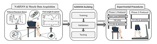
Figure 1.
Methodology overview. NARXNN & Muscle Data Acquisition: Subject foot angle and angular speed (output) are recorded after TA muscle stimulation using filtered random noise as pulse width (input). (a) STM NUCLEO-32F303K8® microcontroller; (b) ISTim stimulator (c) Wearable Inertial Measurement Unit. Pulse width values and foot kinematics (DATA) are used in NARXNN Building to train, validate and built the inverse NARXNN model (input: foot kinematics; output: pulse width). The obtained inverse NARXNN is used in the Experimental Procedures to test trajectory tracking control (TTC) and open loop control strategies under a two-phase experimental protocol.
The proposed FES system was developed to re-establish motor control of the foot in stroke survivors that present severe walking disability. Consequently, the FES system will be important to assist gait at reduced self-selected walking speeds, ranging from 1–2.5 km/h [31]. The main goal of the proposed system is to assist drop foot patients efficiently with a compact, few intrusive, and wearable device. Nevertheless, the system is modular, allowing to scale up all functionalities namely, the number of sensors, number of channels, and control strategies according to other application scenarios.
The present work is divided into three main steps, the (i) NARXNN and Muscle Data Acquisition, the (ii) NARXNN Building, and the (iii) Experimental Procedure, as demonstrated in Figure 1. The first step addresses the acquisition of foot angle and angular velocity data retrieved from the TA muscle stimulation modulating the stimulation pulse width using specific filtered random noise signals. The obtained data was subsequently used to train, validate, and test a NARX neural network model to create an inverse model of the TA muscle. In the last step, the NARX neural network performance was tested when incorporated into different control strategies under experimental procedures divided in two phases.
The chosen microcontroller was the STM NUCLEO-32F303K8® (STMicroelectronics, Geneva, Switzerland), since it is small but has a high range of peripheric features, with a length of 50.29 mm and a width of 18.54 mm. It features I2C and USART communication interfaces and provides 2 USART peripherals. It has an Arm® Cortex®-M4 32-bit CPU with 72 MHz maximum CPU frequency and features 64 Kbytes of Flash memory and 12 Kbytes of SRAM [32]. The processing unit communicates with the IMU and the ISTim via I2C, and serial USART, respectively.
The sampling frequency of the system for data acquisition from MPU6050 was set to 500 Hz to capture the varying dynamics of the foot movement during gait [27]. This sampling frequency was used for all procedures conducted in the present study. The proposed wearable system was designed to provide personalized and time-effective assistance, compensate external disturbances, and provide natural movement detection algorithms.
2.1. Functional Electrical Stimulation
The electrical stimulation was conducted using the ISTim Modular Stimulation System [26,27], which delivers biphasic squared electrical pulses. The electrical pulse parameters range between 0–50 V, 0–503 , and 0–200 Hz, for pulse amplitude, width, and frequency, respectively [33]. The electrical stimulation was delivered to the TA muscle using two skin-surface, self-adhesive electrodes (5 cm; Medel GmbH, Hamburg, Germany) placed over the common peroneal nerve, allowing dorsiflexion of the foot. Considering the anode- and cathode-first biphasic stimulation [34], the cathode electrode was placed near to the head of the fibula and the anode electrode placed on the middle of the fibula.
2.2. Participants
Regarding the creation of the reference trajectories, the participants were approached through a mailing list across the University of Minho community describing the study goal, protocol, and duration. The participants were recruited according to a set of inclusion criteria, as follows: (i) healthy locomotion; (ii) more than 18 years old; (iii) body mass ranging from 45 to 90 kg; and (iv) body height ranging from 1.50 to 1.90 m. We selected 10 able-bodied subjects (6 males, 4 females) for the data acquisition procedure. The participants’ mean age was 23.9 ± 1.64 years, with a mean height of 174.9 ± 7.07 cm, and mean weight of 69.7 ± 7.14 kg.
The trajectory tracking control validation procedures were conducted with an able 23-year-old female subject with 162 cm and 60 kg. All participants provided written and informed consent, according to the ethical conduct defined by the University of Minho Ethics Committee (CEICVS 006/2020) that follows the standards set by the declaration of Helsinki and the Oviedo Convention.
2.3. Modeling the Tibialis Anterior Muscle
The proposed empirical model represents the inverse dynamics of the electrically stimulated muscle. It predicts the pulse width values needed to deliver a personalized stimulation signal to control muscle contraction given the desired trajectory, towards correcting DF in real-time.
2.3.1. NARX Neural Network
NARX is a class of discrete-time non-linear systems that establish non-linear relationships between past observations and future outputs [18]. These models are useful for FES research purposes due to the small number of required parameters and their ability to represent the nonlinear dynamic behaviour of the electrically stimulated muscle [35]. The NARXNN model is represented by Equation (2), as follows:
where is the output predicted by the model, is the input at time . is the non-linear function that describes the system’s behaviour and and are the regression orders of the input and output, respectively. Since the function is a Multilayer Perceptron (MLP), the model represents a NARXNN.
The proposed NARXNN was trained in Series-Parallel mode for more efficient training, considering that the true output is available (pulse width). The NARXNN is a type of recursive neural network that only has feedback between the output and input layers [5]. The dynamic inverse NARXNN model represented by Equation (2) was trained using the foot angle () and its angular velocity () as exogenous reference inputs, represented by in Equation (2). During training, the NARXNN learned the pulse width () as the desired output that would generate the considered foot angle () and respective angular velocity (). For real-time operating conditions and validation purposes, NARXNN considers the estimated pulse width () as input (feedback loop) in addition to the foot angle () and its angular velocity (), as represented in Figure 2. By trial and error, we verified that the NARXNN with only one delayed input fitted the trade-off between maximum accuracy and real-time efficiency.

Figure 2.
Inverse dynamic NARXNN configuration used under real-time and validation conditions. The NARXNN considers as input the estimated pulse width (), the foot angle (), and the foot angle velocity () to generate new predictions ().
2.3.2. NARX Model Data Acquisition
A data acquisition procedure was performed to personalize the NARXNN model to each user’s TA muscle characteristics. It consists of applying different stimulation signals to the TA muscle and recording the resulting foot kinematics (foot angle and angular velocity) using the IMU placed on the subject’s foot. This procedure is represented in Figure 1—NARXNN and Muscle Data Acquisition.
The pulse width was chosen as the controlled variable and the stimulation frequency was adjusted to 30 Hz, the pulse amplitude to 28 V, and the minimum and maximum pulse width to 30 µs and 120 µs, respectively. The NARXNN was trained with real foot movement data from the IMU obtained after stimulating the TA muscle. For this, Filtered Random Noise (FRN) signals were used to shape the pulse width parameter. A frequency analysis of foot kinematics when walking with speeds between 1 Km/h and 2 Km/h determined that the most representative frequencies range between 0.23 and 0.34 Hz (The power spectrum of kinematic signals for each speed is represented in Figure A1 of Appendix A). For assessing the model robustness, TA muscle stimulations were performed by adjusting the pulse width values using FRN signals with three incremental frequencies of 0.1 Hz, 0.2 Hz, and 0.3 Hz to generate slow, intermediate, and fast motion responses, respectively [28]. Three experimental trials were conducted for each FRN pulse frequency to collect diversified data for robust model training. The experimental trials were conducted with a healthy 23-year-old female subject. The system must consider no contact forces during the swing phase; thus, the data acquisition was performed with the subject in a seated position with both feet elevated from the ground.
2.3.3. NARX Model Building
Data (foot angle, foot angular velocity, and the pulse width signals) obtained from the NARXNN and Muscle Data Acquisition procedure were normalized between 0 and 1 using the min-max normalization method. The normalized data were used to train the personalized dynamic inverse model. The goal was to train the model with foot angle, foot angular velocity as inputs, and the expected pulse width as output in order to build a stimulation pulse adaptive neural network. The model was created and preliminarily tested using MATLAB® running on an ASUS® computer with an INTEL® CORETM i73537U processor at 2 GHz. This procedure is represented in Figure 1—NARXNN Building.
The trials’ data were randomly (using “rand” MATLAB function) divided as 70% for training, 15% for validation, and 15% for testing. The NARXNN was built using hyperbolic tangent as activation function and the Levenberg–Marquardt as the training algorithm. The weights were initialized randomly, between −1 and 1, and the NARXNN was trained with two different stopping criteria: upon reaching 500 training epochs or if the validation error increases six times in a row, to avoid overfitting. The validation error consisted of determining the Mean Squared Error (MSE) by comparing the expected values with those output by the NARXNN. We studied NARXNN performance by varying the number of neurons (5, 10, and 20) and hidden layers (1 and 2) towards finding the best performing NN with the smaller number of parameters to be used in the real-time control strategy. The performance of the NARXNN was assessed with the testing dataset, in terms of the goodness of fit (GOF) and the Pearson correlation coefficient (). The GOF provides a measure of how similar a signal is when compared to a given reference, in terms of amplitude. The Pearson correlation coefficient measures linear similarity between the signals.
2.4. Trajectory Tracking Control Strategy
A trajectory tracking control strategy was implemented in the proposed system using a PD controller paired with a NARXNN model. Figure 3 depicts the closed-loop control strategy, where the feedback loop is fed by the foot angle and foot angle velocity, both measured by the foot IMU sensor in real-time.
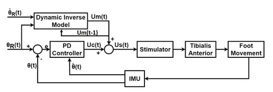
Figure 3.
Closed-loop, Trajectory tracking control diagram, including the PD controller as the feedback component and the Dynamic Inverse Model (NARXNN) as the feedforward component. The control command (pulse width) is generated by combining the feedforward control command () and the feedback control command () and is sent to the stimulator, which delivers the stimulation to tibialis anterior muscle accordingly. The subsequent foot movement is continuously measured by the IMU placed on the subject’s foot in terms of real foot angular velocity and foot angle . The PD controller only considered the foot angle as the reference trajectory, while the Dynamic Inverse Model (NARXNN), considered as references both the foot angle and the foot angle velocity .
The error value, , represents the PD controller input and it is computed as indicated in Equation (3).
where is the desired foot trajectory angle and is the real foot angle measured by the IMU. The PD control command is given by Equation (4).
where is the control variable output of the controller, is the error value given by Equation (3), is the real foot angular velocity, and and are the proportional and derivative gains, respectively. The pulse width value that is sent to the stimulator, , is a sum of the value predicted by the model, , and the control variable from the PD controller, , given by Equation (5).
The trajectory tracking control strategy relies on the gait event detection in order to evoke muscle contraction according to each stage of the gait cycle. The used gait event algorithm was proposed in [36], and relies on the foot’s angular velocity to detect in real-time the Heel Strike (HS), Foot Flat (FF), Middle Mid-Stance (MMST), Heel-Off (HO), Toe-Off (TO) and Middle Mid-Swing (MMSW) using an adaptive finite state machine. The detected gait events are used to trigger the trajectory tracking control during the swing phase given that this is the most affected phase in DF patients [37].
2.4.1. Response Time Delay Removal
It is important to emphasize that the FES actuation has a subject-specific delay linked to the subject’s muscular response time. Therefore, it is important to anticipate this delay in order to track the correct foot angle trajectory in the correspondent gait phase. The response time delay is continually measured during gait, and the response time delay removed in each gait cycle is retrieved from the previous gait cycle. The time delay removal strategy starts by determining the stance phase duration , by measuring the time between heel strike and toe-off events, both detected by the gait event algorithm in real-time [36]. Subsequently, the subject specific time delay () is computed as the time difference between the toe-off events of the reference foot angle trajectory and the measured foot angle trajectory. Figure 4 depicts a case example of a subject-specific time delay removal.

Figure 4.
(a) Determination of the subject’s response time and (b) Removal of the subject’s response time. Blue line represents subject-specific time delay ().
The delay removal is achieved by triggering stimulation at a specific time for each gait cycle, denominated as stimulation time , determined as the difference between and , as indicated in Equation (6).
2.4.2. Reference Trajectory Acquisition
The foot reference trajectory was obtained from 10 healthy subjects walking on a treadmill at three different speeds (1 km/h, 1.5 km/h, and 2 km/h) as mentioned in Section 2.2. An IMU was placed on the subject’s foot to measure his/her kinematic behaviour. The foot angle and foot angular velocity were acquired in real-time during 10 gait cycles for each speed. Note that each gait cycle starts and begins when foot angle and foot angular velocity are 0° and 0 rad/s, respectively. For each walking speed, the foot angle and foot angular velocity reference trajectories were created by performing the average of the 10 retrieved signals, resulting in three-foot angle reference trajectories (Figure 5a–c) and three foot angular velocity reference trajectories (Figure 5d–f).
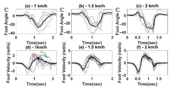
Figure 5.
Reference Trajectories for different speeds, (a,d) 1 km/h; (b,e) 1.5 km/h; (c,f) 2 km/h. Foot angle (top) and angular velocity (bottom). The bold lines represent the final trajectories obtained from averaging all the subject’s trajectories (thin lines).
2.4.3. Trajectory Tracking Control Validation
The trajectory tracking control was validated considering an experimental protocol divided into two phases. For both phases, the control strategies were applied at a frequency of 125 Hz. PD controller was tuned manually until the system was stable, achieving values of 1.5 and 0.7 for and , respectively. The inertial sensor was placed on the surface of the foot. The system was validated with an able 23-year-old female subject with 162 cm and 60 kg [38,39]. The performance of the trajectory tracking control was assessed using GOF and the root mean square error (RMSE). The GOF and RMSE provide objective measures to compare the reference signals with the measured signals obtained by applying the FES control strategy. The advances in this study may be further explored in disabled subjects, since the response of the relaxed muscles of able subjects is similar to that of paralyzed muscle limbs under electrical stimulation [40,41,42,43,44].
Phase I Protocol
The phase I protocol aims the control benchmarking analysis by comparing the performance of feedforward and feedback trajectory tracking control strategy (NARXNN & PD) with the (i) single PD controller (for compensation purposes) and (ii) Open-loop dynamic inverse NARXNN control strategy (OP), as represented in Figure 6. This comparative analysis focused on selecting the most effective controller towards the DF correction application. The validation was performed with the subject seated, keeping the foot elevated from the ground, allowing the ankle to move without restriction. These experimental conditions are easily reproducible in consequent trials and aim at allowing the testing to be conducted without the existence of ground contact forces to the foot. Figure 7a represents the experimental setup. The control strategies were validated with the reference trajectory for three different speeds: 1 km/h, 1.5 km/h, and 2 km/h, conducting 4 trials for each speed.

Figure 6.
Open-loop dynamic inverse NARXNN control strategy. The NARXNN receives the desired foot angle trajectory and predicts the control command , which is sent to the stimulator, delivering stimulation accordingly.

Figure 7.
Validation setup: (a) Phase I protocol: The subject remained in a seated position, undergoing stimulation for the validation of the single feedforward NARXNN model, the single PD controller, and the feedback and feedforward strategy combing a PD with a NARXNN; (b) Phase II protocol: The subjects walked in a treadmill for three different speeds, undergoing stimulation to validate the feedback and feedforward strategy combing a PD with a NARXNN.
Phase II Protocol
The phase II protocol was performed to validate the feedforward and feedback control strategy (PD & NARXNN) for DF correction during gait with the subject walking on the treadmill at three speeds: 1 km/h, 1.5 km/h, and 2 km/h. The range of walking speeds between 1 and 2 km/h aims to focus the system validation on the most severe cases of walking disability as a consequence of a stroke [31]. The validation setup can be seen in Figure 7b. During experimental trials, the subject was instructed not to lift the foot during the swing phase, behaving similar to a DF patient (pseudo-DF-gait). The stimulation was applied in random gait cycles during the simulated DF gait of the subject. The random application of the electrical stimulus aimed to minimize the occurrence of voluntary muscle contractions. Preliminary experimental validations have been performed in literature with healthy subjects using FES to correct drop foot [38,39]. One trial was conducted for each walking speed until 10 gait cycles were completed.
3. Results
3.1. NARXNN Testing
The dynamic inverse NARX was tested alone after training and validation, to infer its ability to predict target FRN signals, under a different number of layers and neurons. This procedure is represented in Figure 1 as the last step of the NARXNN building block. Figure 8 shows the predicted signals (pulse width) overlapped to the reference FRN signals, and respective performance (GOF = 89.05%, 83.9%, and 69.49%) obtained for one trial using a NARXNN with two hidden layers and 20 neurons.

Figure 8.
Inverse dynamic NARXNN model results for the first trial with two hidden layers and 20 neurons: (a) low-frequency FRN, (b) medium-frequency FRN and (c) high-frequency FRN.
The NARNN performance for tracking low, medium, and high-frequency FRN signals was accessed considering a different number of neurons (5, 10, and 20) in a single and double-layer configuration. The performance results in terms of average GOF and ρ coefficient were estimated based on the experimental data and are depicted in Table 1.

Table 1.
Results (GOF and ρ) for NARXNN trained with acquired data for a different number of neurons and hidden layers.
The system computation times were analysed to determine its real-time performance when running in the microcontroller architecture. The obtained computation times regarding the NARXNN prediction, the IMU data acquisition, the communication with the stimulator and the gait event detection algorithm are listed in Table 2. The combination of these values represents the system operating frequency which stands higher than the stimulation frequency (30 Hz). Therefore, the implemented dynamic inverse models present time effective responses, which stand adequate for real-time control. Considering the Table 1 and Table 2 results, the NARXNN with two hidden layers and 10 neurons in each hidden layer was the selected chosen architecture to use in the control strategies of the following experimental procedures (two-phase protocol), to privilege the trade-off between accuracy and time-efficiency.
Table 2.
Mean computation times obtained from the FES system operations.
3.1.1. Phase I Protocol
The results (GOF) obtained regarding the three different control strategies validated at three different speeds are presented in Table 3 and Figure 9.
Table 3.
Control strategies performance (GOF) for phase I protocol.

Figure 9.
Performance comparison between the different control strategies for phase I protocol for 1 km/h, 1.5 km/h, and 2 km/h speeds. (a–c) Foot angle signal obtained from each control strategy for 1 km/h, 1.5 km/h, and 2 km/h, respectively. (d–f) Pulse width signal used for stimulation for 1 km/h, 1.5 km/h, and 2 km/h, respectively. OP: open-loop model composed of NARXNN; PD: a single feedback PD controller; TTC: the trajectory tracking control strategy combing a PD with a NARXNN. PW stands for pulse width and FA stands for foot angle.
The dynamic inverse model in open-loop showed moderate and low performance for the low-speed and higher-speed reference signals, respectively (68.16% (1 km/h), 23.86% (1.5 km/h), 22.19% (2 km/h)). These results indicate that this open-loop control strategy may yield an unstable reference trajectory tracking under walking speed variation, which may result in an inadequate stimulation.
3.1.2. Phase II Protocol
The system validation under phase II protocol was conducted with a healthy subject on a treadmill at 1 km/h, 1.5 km/h, and 2 km/h. Results under phase II protocol for the speed of 1 km/h can be seen in Figure 10. By analysing Figure 10a, at the beginning of the swing phase, the foot angle is 20° lower than the reference trajectory (the reference trajectory retrieved as described in Section 2.4.2). In order to compensate for this disturbance, the controller increases the applied pulse width, as shown in Figure 10c. As the real foot angle approaches the desired trajectory the applied pulse width decreases, as expected, in order to avoid unneeded muscle stimulation, and consequently to prevent the early onset of fatigue (Figure 4). The reference trajectory was set to zero from heel-strike to push-off events to assist only when needed for drop foot correction, aiming at delaying the muscle fatigue. The pulse width is not constant throughout the swing phase, since it changes according to the difference between the desired trajectory and the real foot angle. The foot angle is able to reach the desired reference angles before the heel strike and, due to the pulse width decrease at the heel strike, it is also able to slowly descend towards the ground, generating a natural movement.

Figure 10.
Real-time trajectory tracking control strategy validation at 1 km/h: (a) Measured foot angle (black solid line) and reference foot angle trajectory (dashed green line). (b) Control activation (Gait phase and Control State). The vertical dashed line with blue arrow represents stance-swing transition, while the green arrow indicates the swing-stance transition. (c) Applied pulse width.
The gait cycles related to corrected DF gait by FES were averaged and compared with the pseudo-DF gait and with the healthy gait, to determine if the applied control strategy improved the pseudo-DF gait pattern. The obtained RMSE results comparing the foot angle from healthy gait with pseudo-DF and corrected DF gait are depicted in Table 4. These results suggest that the proposed trajectory tracking control was able to improve the foot motion in 21.41%, 45.82%, and 37.76% for the walking speeds of 1 km/h, 1.5 km/h, and 2 km/h, respectively.
Table 4.
RMSE values obtained by comparing healthy gait cycles with the pseudo-DF and the corrected DF gait cycles for three walking speeds.
Figure 11 shows that in the pseudo-DF gait the foot does not rise above 0° at heel strike. However, when the trajectory tracking control strategy is applied, the foot follows the desired trajectory, raising above 0°, and demonstrating a healthy behaviour.

Figure 11.
Foot angle obtained by measuring DF gait (blue line) in comparison with foot angle measured during DF correction (black line) using the feedback and feedforward control strategy at a walking speed of 1.5 km/h. The black line represents the average of all gait cycles obtained in DF correcting conditions. The green line represents a healthy foot angle trajectory.
4. Discussion
A real-time wearable FES system for DF correction was presented and validated in a two-phase protocol to compare different control approaches and to infer about the system’s ability to correct DF during gait.
Table 1 analysis suggests that the difference in GOF between the results for the NARXNN with 20 neurons trained with 1 and 2 hidden layers is reduced, being 1.28% and 1.3% for low and medium-frequency FRN signals, respectively. For the high-frequency FRN signals, the difference in GOF increases to 8.01%. Despite this difference for high-frequency FRN signals, the ρ values stood similar with average difference values of 0.095, 0.007, and 0.017 regarding low, medium, and high-frequency FRN signals respectively. The NARXNNs showed higher performance for low-frequency signal predictions, with a GOF of 81.41%, when compared to the performance for high-frequency signal predictions, with a GOF of 68.07%. The prediction time responses of the models were also studied, showing that the NARXNNs with 10 neurons had the fastest response (7.0 ± 0.327 ms).
The obtained results for phase I protocol show that the feedforward and feedback-based trajectory tracking control strategy had the best performance when compared to the other control strategies. However, for the highest speed reference (2 km/h) the accuracy has decreased 69.54% (GOF = 23.72%), which might be related with the fact that the NARXNN was trained with FRN signals with frequencies ranging from 0.1–0.3 Hz. The inclusion of a NARXNN into a closed-loop PD controller increased prediction performance (Table 3), and a visual inspection of Figure 9 shows that the corrected DF gait trajectory presents higher similarity comparing with the healthy gait trajectory. The lower performance for the 2 km/h speed might be related to the considerable differences in initial conditions, i.e., the difference between the initial real foot angle and the initial reference trajectory values, creating a delayed pulse width, which results in a delayed tracking response. This issue was not observed in the phase II protocol since the initial conditions were fixed, i.e., the user started the walking on a treadmill in foot flat event, where the foot angle is approximate 0°. The results obtained for phase I protocol point show considerable improvements (62%) in using a feedback and feedforward control strategy (combining a PID and a neural network), as previously advances in similar studies [17].
Additionally, the proposed feedback and feedforward control strategy presents considerable improvements when comparing pseudo-DF gait and corrected DF gait with healthy gait, namely, 21.41%, 45.82%, and 37.76% for the walking speeds of 1 km/h, 1.5 km/h, and 2 km/h, respectively. These results suggest that the use of FES under the proposed feedback and feedforward control strategy allowed a healthier motor control of the foot during gait. Despite promising results, the existing angle error between reference trajectory and corrected DF trajectory may be related to the used reference. The creation of the angle reference included subject with considerable difference in height which may not be the most adequate for the subjected that conducted the system validation. Nevertheless, the results from our study regarding the feedback and feedforward control strategy during gait stand in accordance with a study with a similar experimental setup [9]. The trajectory tracking control strategy proposed in our study achieved normalized RMSE of 0.305, 0.203, and 0.239 degrees for walking speeds of 1, 1.5, and 2 km/h, respectively. The iterative learning control proposed in [9,45] presented similar performance in the initial iterations (normalized RMSE of 0.25 degrees); however it converged to a minimal error performance in the subsequent control iterations (normalized RMSE of 0.05 degrees). Moreover, the study [11] advances in the use of FES to control the foot pitch and roll motion in paretic gait, while achieving promising results, having normalized RMSE values for the foot pitch of 0.08 degrees. Despite requiring further experimental trials, our study contribution regarding similar studies [9] relates to the use of a fully wearable FES system that runs in real-time a feedback and feedforward control strategy to correct drop foot gait.
Similar trajectory tracking strategies have been proposed in the literature [17,46]. However, the study conducted in this paper advances [17] by embedding a feedforward and feedback control strategy in a completely wearable and real-time FES system. Moreover, the work in [21] proposes a wearable FES prototype using a fuzzy logic control, however, the obtained results suggested the need to include a parameter adjustment algorithm to run during the stimulation. The present study tackles the need to develop wearable FES systems with embedded control, and the use of a NARXNN allows the automatic parameter adjustment to provide an optimized stimulation pattern. The FES system was created to be personalized for each subject, requiring minimal-to-null inputs from the end-user for real-time use. In this sense, the pulse intensity and frequency parameters are initially fixed to the best-suited values, not requiring any type of adjustment during stimulation. Moreover, the NARXNN automatically adjusts the pulse width in real-time to the subject’s needs.
5. Limitations and Future Directions
In this study, we presented an initial design of feedback and feedforward control strategy by combining a PD and a NARX neural network-integrated in an FES wearable system, for real-time DF correction during gait. Our main goal was to conduct initial tests aiming for the system validation and to evaluate the NARX as a feedforward component from the feedback and feedforward control strategy. The main limitation of this study relies on the reduced number of subjects used for validation purposes. In fact, despite promising results and the real-time validations conducted, the proposed system will undergo extensive validation with an increased population size by including patients with drop foot as the target end-users. The NARX neural network was able to modulate TA muscle for slow walking speeds. Despite this, the model will be improved to allow assistance in faster walking speeds, by training the NARXNN with FRN signals with higher frequency. Additionally, future developments on this research will include the execution of the stimulation strategies in different days for the same subject to assess the stimulation response variability day by day. This research will also progress to improve the control time-effectiveness and time-delay quantification during gait at different speeds.
6. Conclusions
This paper proposes a real-time trajectory tracking control strategy, based on a NARXNN combined with a PD, to control the foot angle trajectory using a newly designed wearable FES system for assist-as-needed DF correction. Under DF gait conditions, the assistance was focused on the swing phase, which was timely detected through an adaptive gait event detection algorithm. The findings suggest that combining feedforward NARX and a feedback PD controller may yield the best performance when compared to the use of a single feedforward NARX or a single feedback PD controller. Furthermore, the optimized NARXNN architecture showed to be adequate in correcting DF of the participating subject in real-time settings and its inclusion in the feedback and feedforward control strategy enabled personalized and time-effective assistance by considering the user-specific non-linear TA muscle characteristics.
The study conducted in this paper allowed to conclude that the FES system stood as an effective tool for real-time electrical stimulation of the TA muscle. Moreover, the proposed control strategy combining a NARXNN with a PD controller revealed promising results, despite the reduced number of participants in the experimental trials. These results potentiate further investigation with the proposed system with an heterogenous group of participants.
Author Contributions
Conceptualization, C.P.S. and J.M.M.; methodology, S.C., A.C. and J.M.M.; Software, A.C.; funding acquisition, S.C., J.F. and C.P.S.; investigation, S.C. and A.C.; writing—original draft preparation, S.C. and A.C.; writing—review and editing, J.F., J.M.M. and C.P.S. All authors have read and agreed to the published version of the manuscript.
Funding
This work has been supported by the Fundação para a Ciência e Tecnologia (FCT) with the Reference Scholarship under Grant SFRH/BD/147878/2019 and under the national support to R&D units grant, through the reference project UIDB/04436/2020 and UIDP/04436/2020. This work was supported by FCT, through IDMEC, under LAETA, project UIDB/50022/2020.
Institutional Review Board Statement
The study was conducted according to the guidelines of the Declaration of Helsinki, and approved by the Institutional Review Board of University of Minho (CEICVS 006/2020).
Informed Consent Statement
Informed consent was obtained from all subjects involved in the study.
Conflicts of Interest
The authors declare no conflict of interest.
Appendix A
Figure A1 represents the spectral frequency analysis conducted for the kinematic signals depicted in Figure 5. Results of Figure A1 state that the frequencies with the highest power for the speeds of 1 km/h (Figure A1a), 1.5 km/h (Figure A1b), and 2 km/h (Figure A1c) are 0.23 Hz, 0.29 Hz, and 0.34 Hz, respectively. Furthermore, Table A1 presents the frequencies with highest power and energy share below 0.3 Hz for the speeds of 1 km/h, 1.5 km/h and 2 km/h.

Figure A1.
Spectral frequency analysis of the kinematic foot signals represented in Figure 5, for the speeds of: (a) 1 km/h, (b) 1.5 km/h, (c) 2 km/h.
Table A1.
Results from spectral frequency analysis for the kinematic foot signals at the speeds of 1 km/h, 1.5 km/h and 2 km/h.
Table A1.
Results from spectral frequency analysis for the kinematic foot signals at the speeds of 1 km/h, 1.5 km/h and 2 km/h.
| Velocity (km/h) | Frequency with Highest Power | Energy (W/Hz) for Interval [0–0.3] Hz | Energy (W/Hz) for Interval [0–0.2] Hz | Energy (W/Hz) for Interval [0–0.1] Hz |
|---|---|---|---|---|
| 1 | 0.23 Hz | 3.09 × 10⁻² | 2.20 × 10⁻² | 1.4 × 10⁻² |
| 1.5 | 0.29 Hz | 9.2 × 10⁻⁴ | 6.9 × 10⁻⁴ | 4.6 × 10⁻⁴ |
| 2 | 0.34 Hz | 1.8 × 10⁻³ | 1.3 × 10⁻³ | 8.8 × 10⁻⁴ |
References
- Kesar, T.; Chou, L.W.; Binder-Macleod, A.S. Effects of stimulation frequency versus pulse duration modulation on muscle fatigue. J. Electromyogr. Kinesiol. 2008, 18, 662–671. [Google Scholar] [CrossRef]
- Hunt, K.J.; Munih, M.; de Donaldson, N.; Barr, F.M.D. Investigation of the Hammerstein hypothesis in the modeling of electrically stimulated muscle. IEEE Trans. Biomed. Eng. 1998, 45, 998–1009. [Google Scholar] [CrossRef]
- Melo, P.L.; Silva, M.T.; Martins, J.M.; Newman, D.J. Technical developments of functional electrical stimulation to correct drop foot: Sensing, actuation and control strategies. Clin. Biomech. 2015, 30, 101–113. [Google Scholar] [CrossRef]
- Brunetti, F.; Garay, A.; Moreno, J.C.; Pons, J.L. Enhancing functional electrical stimulation for emerging rehabilitation robotics in the framework of hyper project. In Proceedings of the 2011 IEEE International Conference on Rehabilitation Robotics, Zurich, Switzerland, 29 June–1 July 2011; pp. 1–6. [Google Scholar]
- Yassin, I.M.; Jailani, R.; Ali, M.S.A.M.; Baharom, R.; Hassan, A.H.A.; Rizman, Z.I. Comparison between cascade forward and multi-layer perceptron neural networks for NARX functional electrical stimulation (FES)-based muscle model. Int. J. Adv. Sci. Eng. Inf. Technol. 2017, 7, 215–221. [Google Scholar] [CrossRef][Green Version]
- Ghani, N.A.M.; Kamaruddin, S.B.A.; Ramli, N.M.; Nasir, N.B.M.; Kader, B.S.B.K.; Huq, M.S. The quadriceps muscle of knee joint modelling using neural network approach: Part 1. In Proceedings of the 2016 IEEE Conference on e-Learning, e-Management and e-Services (IC3e), Langkawi, Malaysia, 10–12 October 2016; pp. 52–57. [Google Scholar]
- Imatz-Ojanguren, E.; Irigoyen, E.; Valencia-Blanco, D.; Keller, T. Neuro-fuzzy models for hand movements induced by functional electrical stimulation in able-bodied and hemiplegic subjects. Med. Eng. Phys. 2016, 38, 1214–1222. [Google Scholar] [CrossRef]
- Liberson, W.T.; Holmquest, H.J.; Scot, D.; Dow, M. Functional electrotherapy: Stimulation of the peroneal nerve synchronized with the swing phase of the gait of hemiplegic patients. Arch. Phys. Med. Rehabil. 1961, 42, 101–105. [Google Scholar]
- Valtin, M.; Seel, T.; Raisch, J.; Schauer, T. Iterative learning control of drop foot stimulation with array electrodes for selective muscle activation. IFAC Proc. Vol. 2014, 19, 6587–6592. [Google Scholar] [CrossRef]
- Seel, T.; Laidig, D.; Valtin, M.; Werner, C.; Raisch, J.; Schauer, T. Feedback control of foot eversion in the adaptive peroneal stimulator. In Proceedings of the 22nd Mediterranean Conference on Control and Automation, Palermo, Italy, 16–19 June 2014; pp. 1482–1487. [Google Scholar] [CrossRef]
- Seel, T.; Werner, C.; Schauer, T. The adaptive drop foot stimulator–Multivariable learning control of foot pitch and roll motion in paretic gait. Med. Eng. Phys. 2016, 38, 1205–1213. [Google Scholar] [CrossRef] [PubMed]
- Pedrocchi, A.; Ferrante, S.; de Momi, E.; Ferrigno, G. Error mapping controller: A closed loop neuroprosthesis controlled by artificial neural networks. J. Neuroeng. Rehabil. 2006, 3, 1–13. [Google Scholar] [CrossRef] [PubMed][Green Version]
- Li, Z.; Hayashibe, M.; Andreu, D.; Guiraud, D. Real-time closed-loop FES control of muscle activation with evoked EMG feedback. Proceedings ot the 2015 7th International IEEE/EMBS Conference on Neural Engineering (NER), Montpellier, France, 22–24 April 2015; pp. 623–626. [Google Scholar] [CrossRef]
- Lynch, C.L.; Popovic, M.R. Functional Electrical Stimulation. IEEE Control Syst. 2008, 28, 40–50. [Google Scholar]
- Riess, J.A.; Abbas, J.J. Adaptive neural network control of cyclic movements using functional neuromuscular stimulation. IEEE Trans. Rehabil. Eng. 2000, 8, 42–52. [Google Scholar] [CrossRef] [PubMed]
- Le, F.; Markovsky, I.; Freeman, C.T.; Rogers, E. Identification of electrically stimulated muscle models of stroke patients. Control Eng. Pract. 2010, 18, 396–407. [Google Scholar] [CrossRef]
- Chen, Y.L.; Chen, S.C.; Chen, W.L.; Hsiao, C.C.; Kuo, T.S.; Lai, J.S. Neural network and fuzzy control in FES-assisted locomotion for the hemiplegic. J. Med. Eng. Technol. 2004, 28, 32–38. [Google Scholar] [CrossRef]
- Popov, N.S.; Đozić, D.J.; Stanković, M.; Krajoski, G.M.; Stanišić, D. Development of a closed loop FES system based on NARX radial based network. IFMBE Proc. 2015, 50, 70–74. [Google Scholar]
- Wu, Y.; Song, Q.; Yang, X.; Lan, L. Recurrent neural network control of functional electrical stimulation systems. In Proceedings of the 2006 International Conference on Biomedical and Pharmaceutical Engineering, Singapore, 11–14 December 2006; pp. 400–404. [Google Scholar]
- Qiu, S.; He, F.; Tang, J.; Xu, J.; Zhang, L.; Zhao, X.; Qi, H.; Zhou, P.; Cheng, X.; Wan, B.; et al. Intelligent algorithm tuning PID method of function electrical stimulation using knee joint angle. In Proceedings of the 2014 36th Annual International Conference of the IEEE Engineering in Medicine and Biology Society, Chicago, IL, USA, 26–30 August 2014; pp. 2561–2564. [Google Scholar]
- Basith, A.L.; Arifin, A.; Arrofiqi, F.; Watanabe, T.; Nuh, M. Embedded fuzzy logic controller for functional electrical stimulation system. In Proceedings of the 2016 International Seminar on Intelligent Technology and Its Applications (ISITIA), Lombok, Indonesia, 28–30 July 2016; pp. 89–94. [Google Scholar]
- Resquín, F.; Pons, J.L.; Brunetti, F.; Ibáñez, J.; Gonzalez-Vargas, J. Feedback error learning controller for functional electrical stimulation assistance in a hybrid robotic system for reaching rehabilitation. Eur. J. Transl. Myol. 2016, 26, 255–261. [Google Scholar] [CrossRef] [PubMed]
- Tu, X.; Li, J.; Li, J.; Su, C.; Zhang, S.; Li, H.; Cao, J.; He, J. Model-Based Hybrid Cooperative Control of Hip-Knee Exoskeleton and FES Induced Ankle Muscles for Gait Rehabilitation. Int. J. Pattern Recognit. Artif. Intell. 2017, 31, 1759019. [Google Scholar] [CrossRef]
- Ferrarin, M.; Palazzo, F.; Riener, R.; Quintern, J. Model-based control of FES-induced single joint movements. IEEE Trans. Neural Syst. Rehabil. Eng. 2001, 9, 245–257. [Google Scholar] [CrossRef]
- Ferrante, S.; Iannò, M.; De Momi, E.; Pedrocchi, A.; Ferrarin, M.; Ferrigno, G. Artificial Neural Network Closed Loop Control Technique for FES Applications. Available online: https://www.researchgate.net/publication/242181513 (accessed on 26 October 2021).
- Bouri, M.; Selfslagh, A.; Campos, D.; Yonamine, S.; Donati, A.R.C.; Shokur, S. Closed-Loop Functional Electrical Stimulation for Gait Training for Patients with Paraplegia. In Proceedings of the 2018 IEEE International Conference on Robotics and Biomimetics (ROBIO), Kuala Lumpur, Malaysia, 12–15 December 2018; pp. 1489–1495. [Google Scholar]
- Müller, P.; del Ama, A.J.; Moreno, J.C.; Schauer, T. Adaptive multichannel FES neuroprosthesis with learning control and automatic gait assessment. J. Neuroeng. Rehabil. 2020, 17, 1–20. [Google Scholar] [CrossRef]
- de Melo, P.L. A Novel Functional Electrical Stimulation System and Strategies for Motor Rehabilitation. Ph.D. Thesis, Universidade de Lisboa-Instituto Superior T’ecnico, Lisboa, Portugal, 2014. [Google Scholar]
- Correia, A.; Martins, J.M.; Santos, C.P. Functional Electrical Stimulation for Gait Rehabilitation. In Proceedings of the XV Mediterranean Conference on Medical and Biological Engineering and Computing—MEDICON 2019, Coimbra, Portugal, 26–28 September 2019; Volume 76, pp. 1954–1966. [Google Scholar]
- Figueiredo, J.; Moreno, J.C.; Santos, C.P. Wearable Inertial Sensor System towards Daily Human Kinematic Gait Analysis: Benchmarking. Sensors 2020, 20, 2185. [Google Scholar] [CrossRef]
- Beaman, C.B.; Peterson, C.L.; Neptune, R.R.; Kautz, S.A. Differences in self-selected and fastest-comfortable walking in post-stroke hemiparetic persons. Gait Posture 2010, 31, 311–316. [Google Scholar] [CrossRef] [PubMed]
- STM32F303K8-Mainstream Mixed Signals Mcus Arm Cortex-M4 Core with DSP and FPU, 64 Kbytes of Flash Memory, 72 MHz CPU, CCM, 12-bit ADC 5 MSPS, Comparators, op-amp-STMicroelectronics. Available online: https://www.st.com/en/microcontrollers-microprocessors/stm32f303k8.html (accessed on 22 July 2021).
- Cikajlo, I.; Matjačić, Z.; Bajd, T.; Futami, R. Sensory supported FES control in gait training of incomplete spinal cord injury persons. Artif. Organs 2005, 29, 459–461. [Google Scholar] [CrossRef] [PubMed]
- Reilly, J.P. Applied Bioelectricity; Springer: New York, NY, USA, 1998. [Google Scholar]
- Previdi, F.; Carpanzano, E. Design of a gain scheduling controller for knee-joint angle control by using functional electrical stimulation. IEEE Trans. Control Syst. Technol. 2003, 11, 310–324. [Google Scholar] [CrossRef]
- Figueiredo, J.; Félix, P.; Costa, L.; Moreno, J.C.; Santos, C.P. Gait Event Detection in Controlled and Real-Life Situations: Repeated Measures from Healthy Subjects. IEEE Trans. Neural Syst. Rehabil. Eng. 2018, 26, 1945–1956. [Google Scholar] [CrossRef]
- Umberger, B.R. Stance and swing phase costs in human walking. J. R. Soc. Interface 2010, 7, 1329–1340. [Google Scholar] [CrossRef]
- Breen, P.P.; O’Keeffe, D.T.; Conway, R.; Lyons, G.M. A system for the delivery of programmable, adaptive stimulation intensity envelopes for drop foot correction applications. Med. Eng. Phys. 2006, 28, 177–186. [Google Scholar] [CrossRef]
- Yeom, H.; Chang, Y.H. Autogenic EMG-controlled functional electrical stimulation for ankle dorsiflexion control. J. Neurosci. Methods 2010, 193, 118–125. [Google Scholar] [CrossRef] [PubMed]
- Chang, G.C.; Luh, J.J.; Liao, G.D.; Lai, J.S.; Cheng, C.K.; Kuo, B.L.; Kuo, T.S. A neuro-control system for the knee joint position control with quadriceps stimulation. IEEE Trans. Rehabil. Eng. 1997, 5, 2–11. [Google Scholar] [CrossRef] [PubMed]
- Hausdorff, J.M.; Durfee, W.K. Open-loop position control of the knee joint using electrical stimulation of the quadriceps and hamstrings. Med. Biol. Eng. Comput. 1991, 29, 269–280. [Google Scholar] [CrossRef]
- Sharma, N.; Gregory, C.M.; Dixon, W.E. Predictor-based compensation for electromechanical delay during neuromuscular electrical stimulation. IEEE Trans. Neural Syst. Rehabil. Eng. 2011, 19, 601–611. [Google Scholar] [CrossRef] [PubMed]
- Kurosawa, K.; Futami, R.; Watanabe, T.; Hoshimiya, N. Joint angle control by FES using a feedback error learning controller. IEEE Trans. Neural Syst. Rehabil. Eng. 2005, 13, 359–371. [Google Scholar] [CrossRef] [PubMed]
- Ibitoye, M.O.; Hamzaid, N.A.; Hasnan, N.; Wahab, A.K.A.; Davis, G.M. Strategies for Rapid Muscle Fatigue Reduction during FES Exercise in Individuals with Spinal Cord Injury: A Systematic Review. PLoS ONE 2016, 11, e0149024. [Google Scholar] [CrossRef]
- Seel, T.; Valtin, M.; Werner, C.; Schauer, T. Multivariable Control of Foot Motion During Gait by Peroneal Nerve Stimulation via two Skin Electrodes. IFAC-PapersOnLine 2015, 48, 315–320. [Google Scholar] [CrossRef]
- Downey, R.J.; Cheng, T.H.; Bellman, M.J.; Dixon, W.E. Closed-Loop Asynchronous Neuromuscular Electrical Stimulation Prolongs Functional Movements in the Lower Body. IEEE Trans. Neural Syst. Rehabil. Eng. 2015, 23, 1117–1127. [Google Scholar] [CrossRef] [PubMed]
Publisher’s Note: MDPI stays neutral with regard to jurisdictional claims in published maps and institutional affiliations. |
© 2021 by the authors. Licensee MDPI, Basel, Switzerland. This article is an open access article distributed under the terms and conditions of the Creative Commons Attribution (CC BY) license (https://creativecommons.org/licenses/by/4.0/).