
Development and Implementation of an Anthropomorphic Underactuated Prosthesis with Adaptive Grip


Abstract
:1. Introduction
2. Available Adaptive Hand Prostheses with Adaptive Gripping System
2.1. Commercial Devices
2.2. Research Devices
3. Overview of the Main Mechanisms Used in Prosthetics
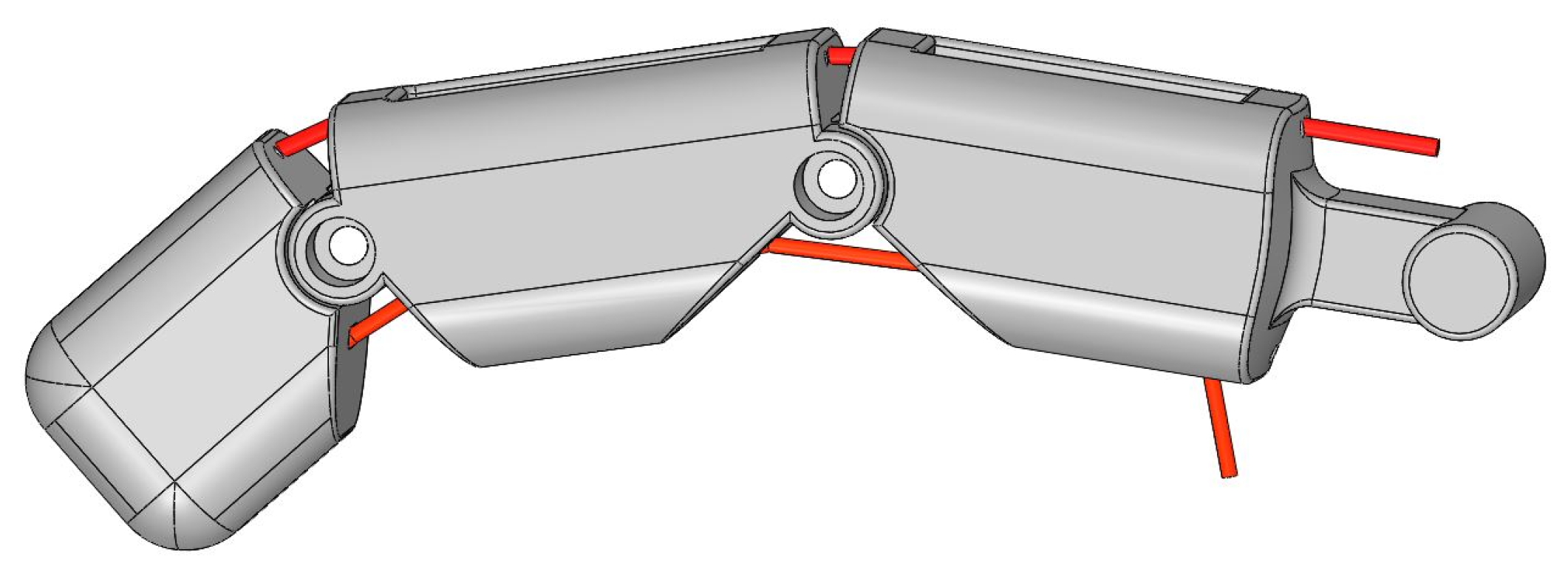
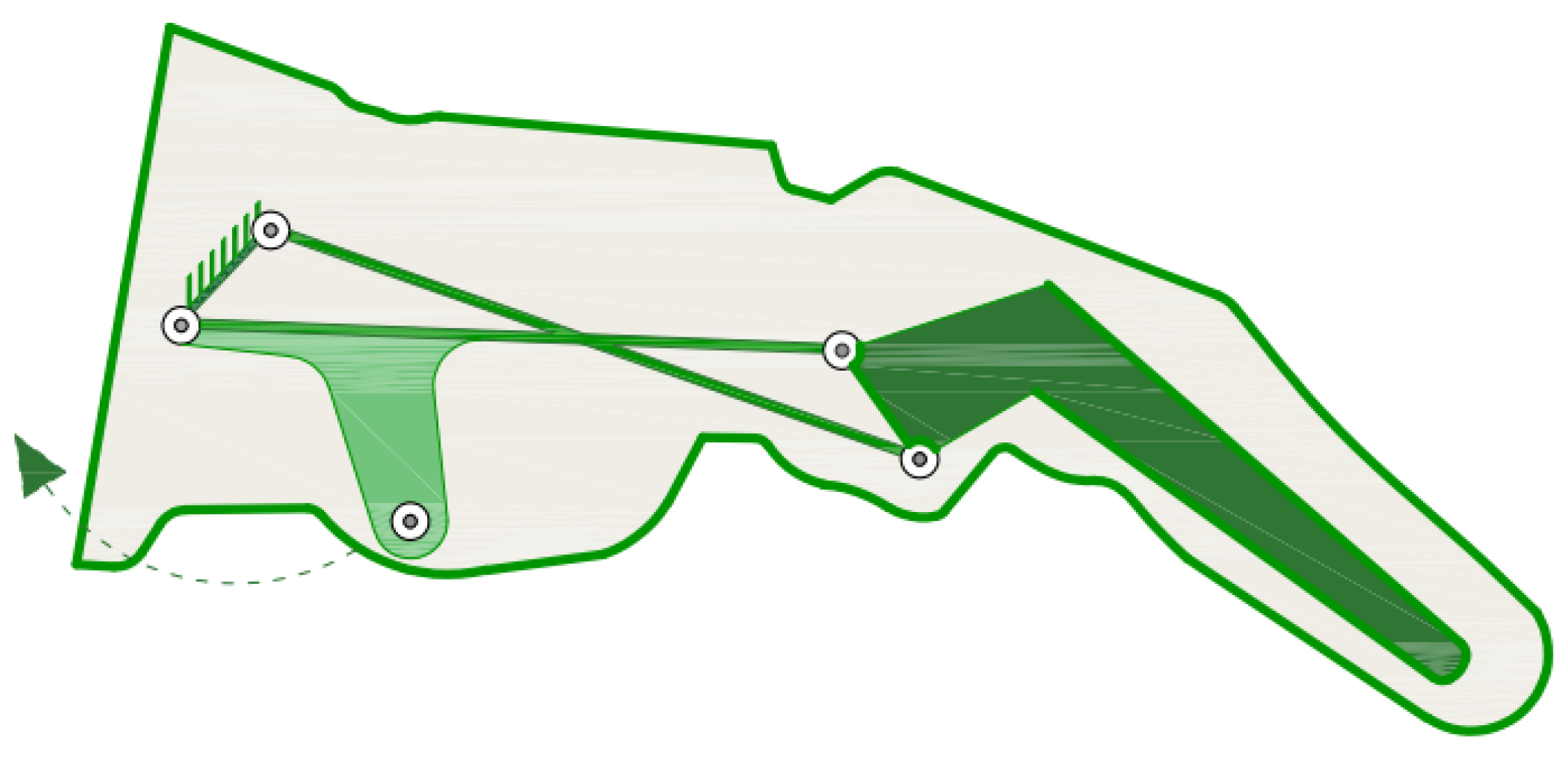
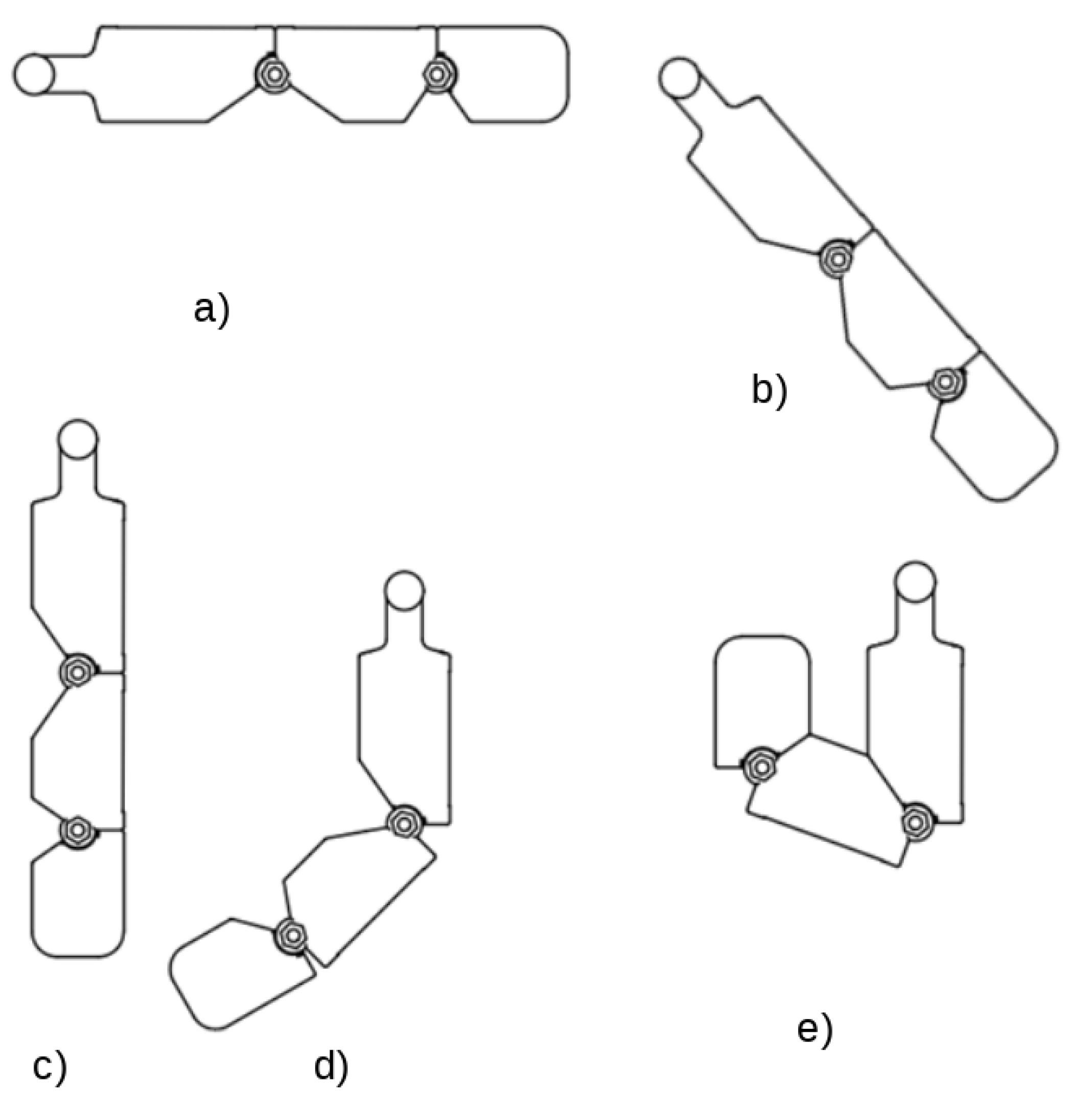
3.1. Underactuated Mechanisms for a Single Finger
3.2. Underactuated Mechanisms for Multiple Fingers
4. Proposed Adaptive Grip Prototype Design
4.1. Dimensions and Range of Motion
4.2. Number of Actuators
- One motor is connected to five fingers.
- Two motors: one controls the thumb flexion, the other controls the remaining fingers.
- Three motors: one motor for the thumb, one for the index finger, and one for the remaining fingers.
- Four motors: two motors for the thumb, one for the index finger, and one for the remaining fingers. As this type of configuration is similar to the three-motor arrangement, it is not considered in this study.
- Five motors: one for each finger.
- Six motors: two for the thumb and one for each remaining finger.
4.3. Design of Index, Middle, Annular, and Little Fingers
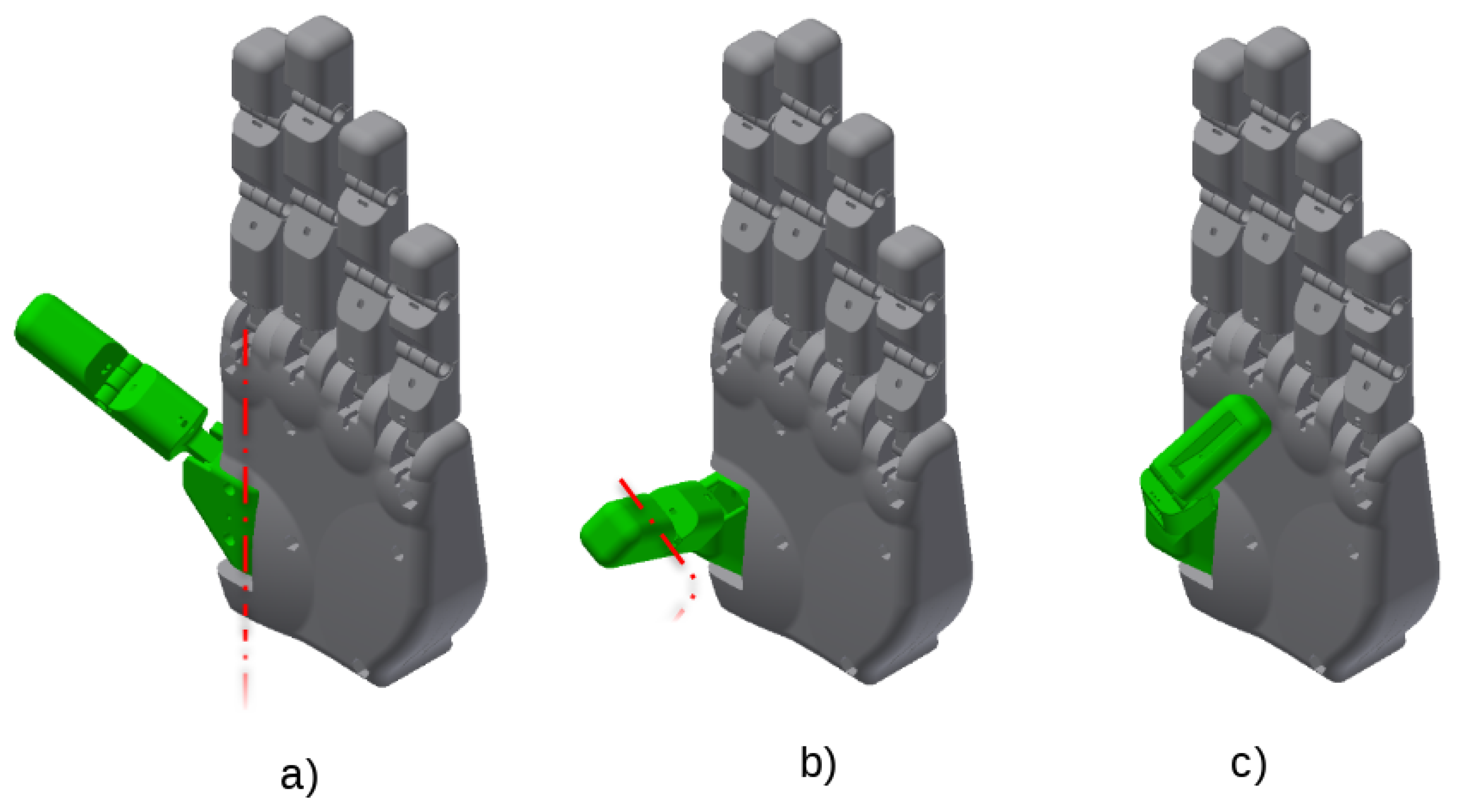
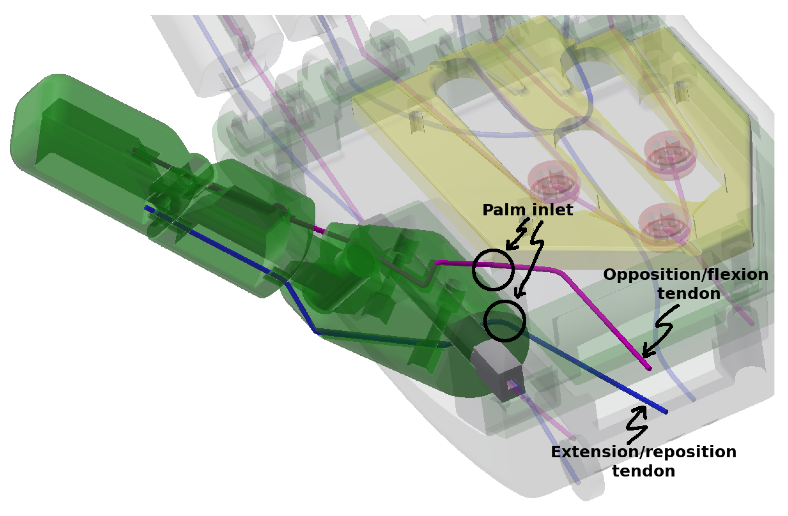
4.4. Design of the Thumb
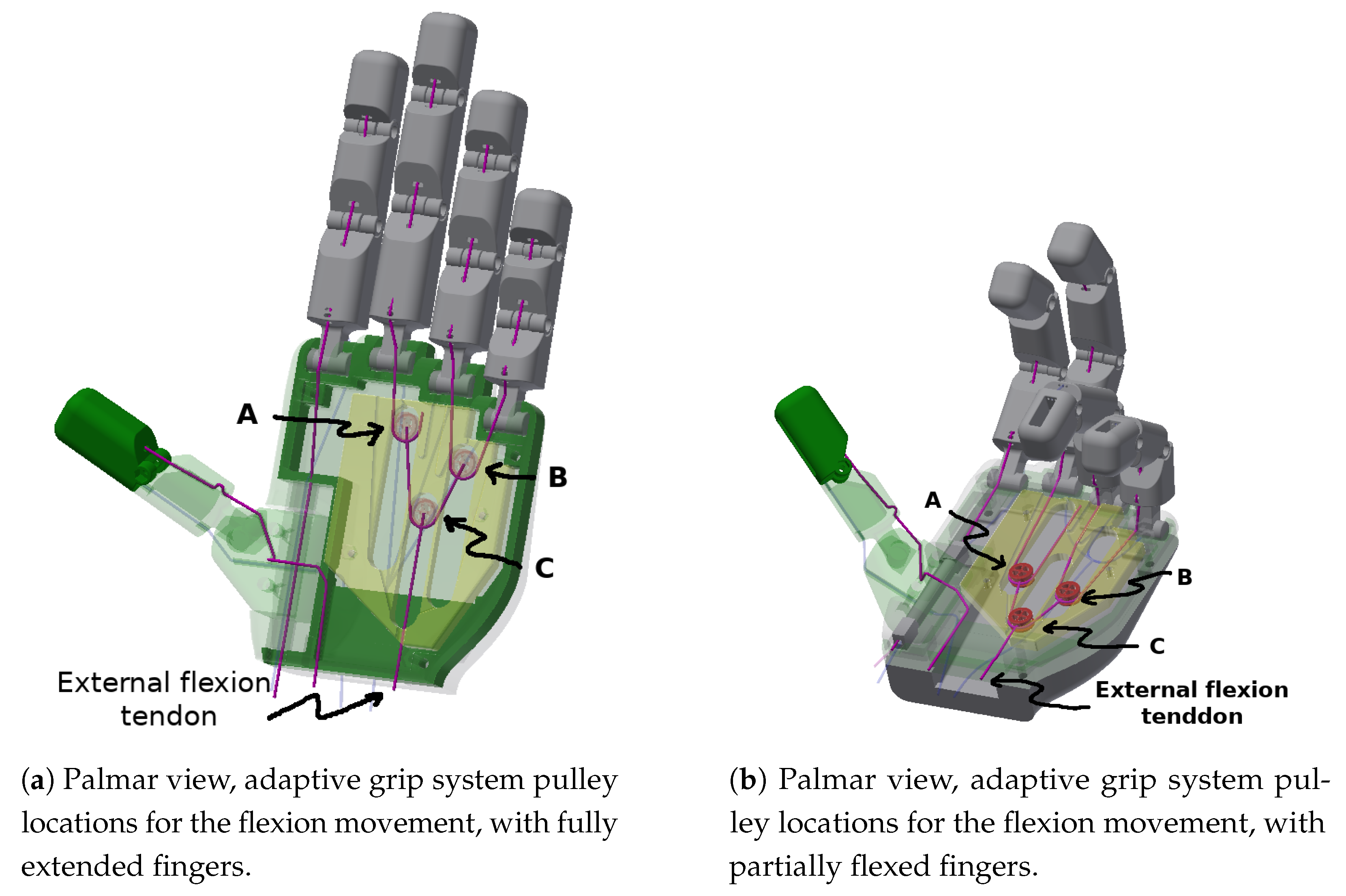
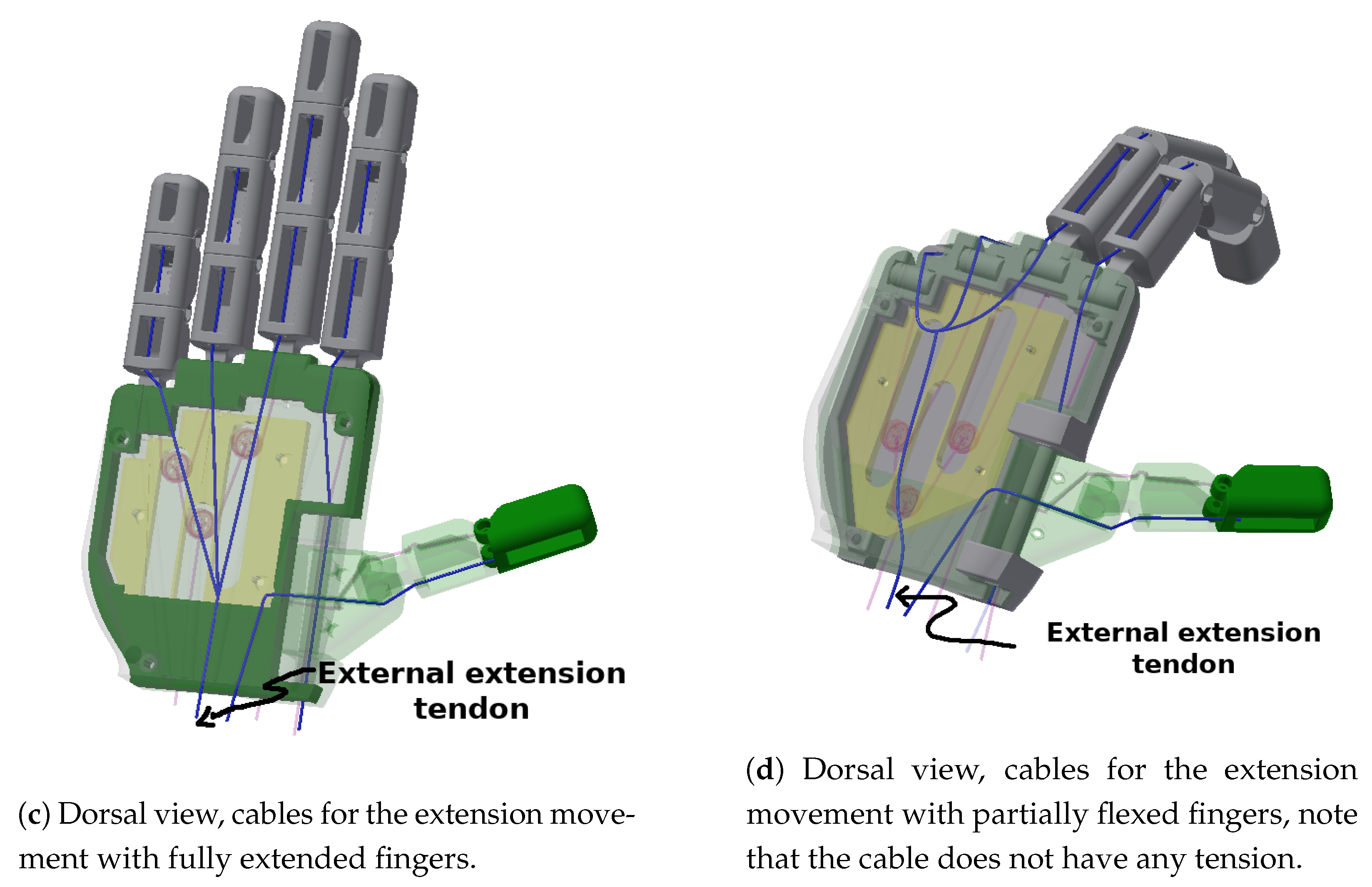
4.5. Adaptive Grip Mechanism Design
4.6. Actuators
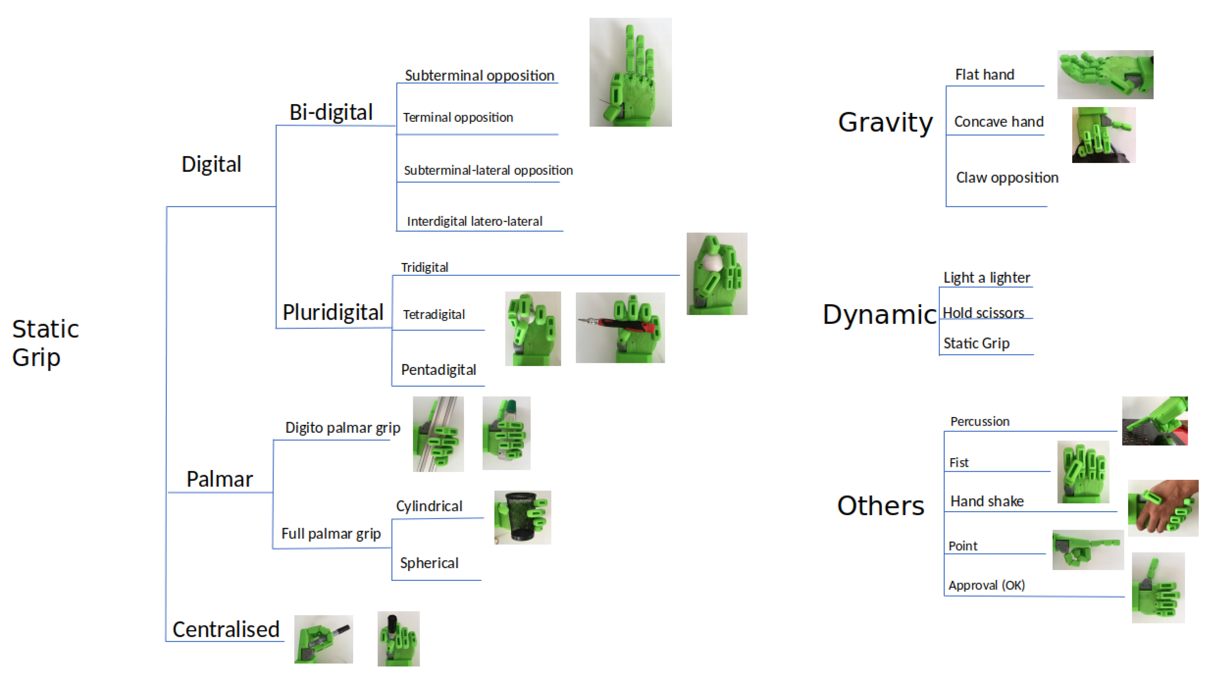
5. Results: Performance Tests, Gripping of Various Objects
5.1. Digital Grips
5.1.1. Bi-Digital Grips
Terminal Opposition
Subterminal Opposition
Subterminal Lateral-Opposition
Subterminal Interdigital Latero-Lateral
5.1.2. Multidigital Grips
Tridigital Grip
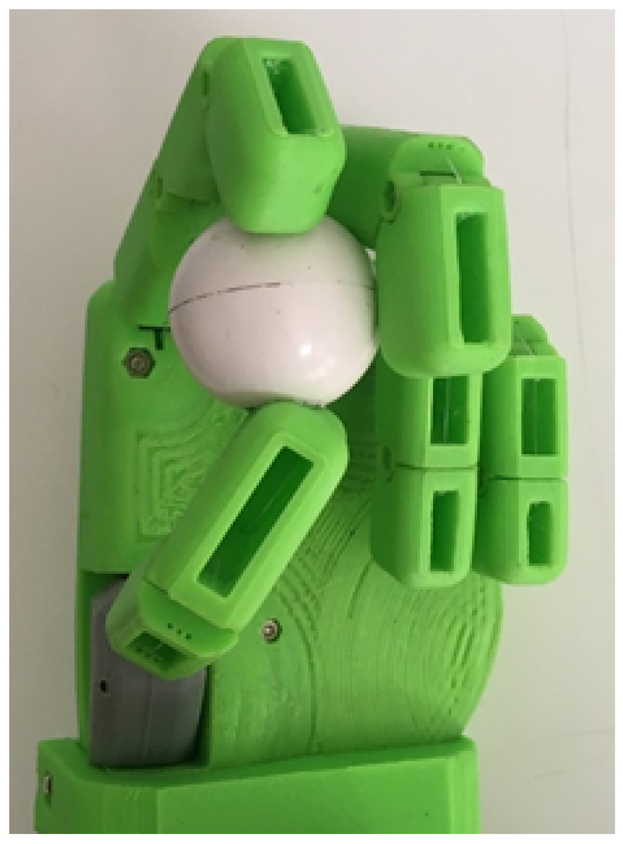
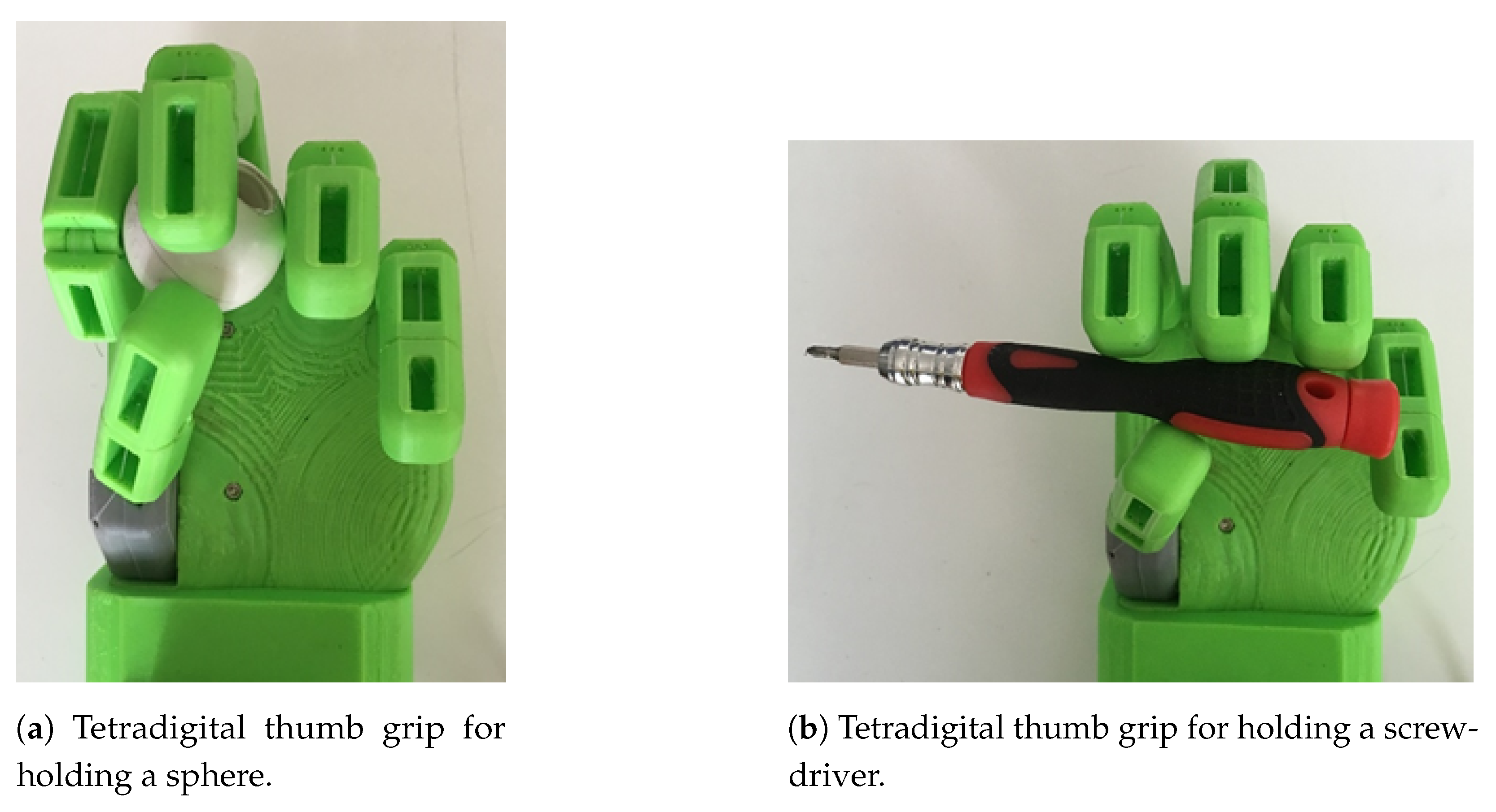
Tetradigital Grip
Pentadigital Grip
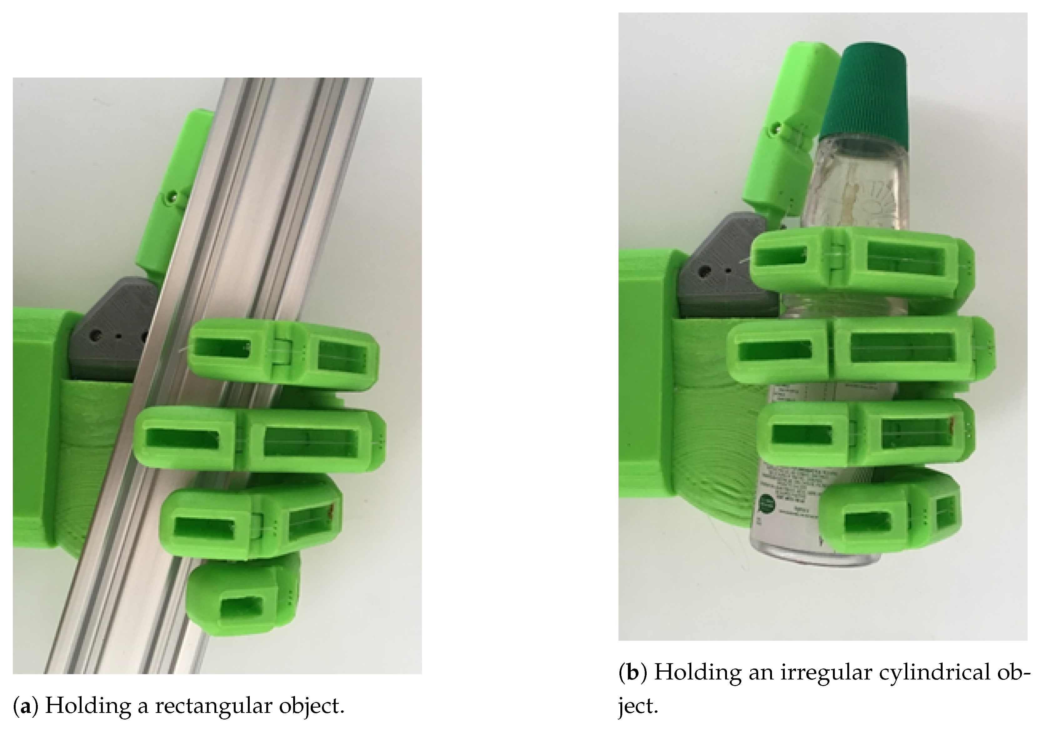
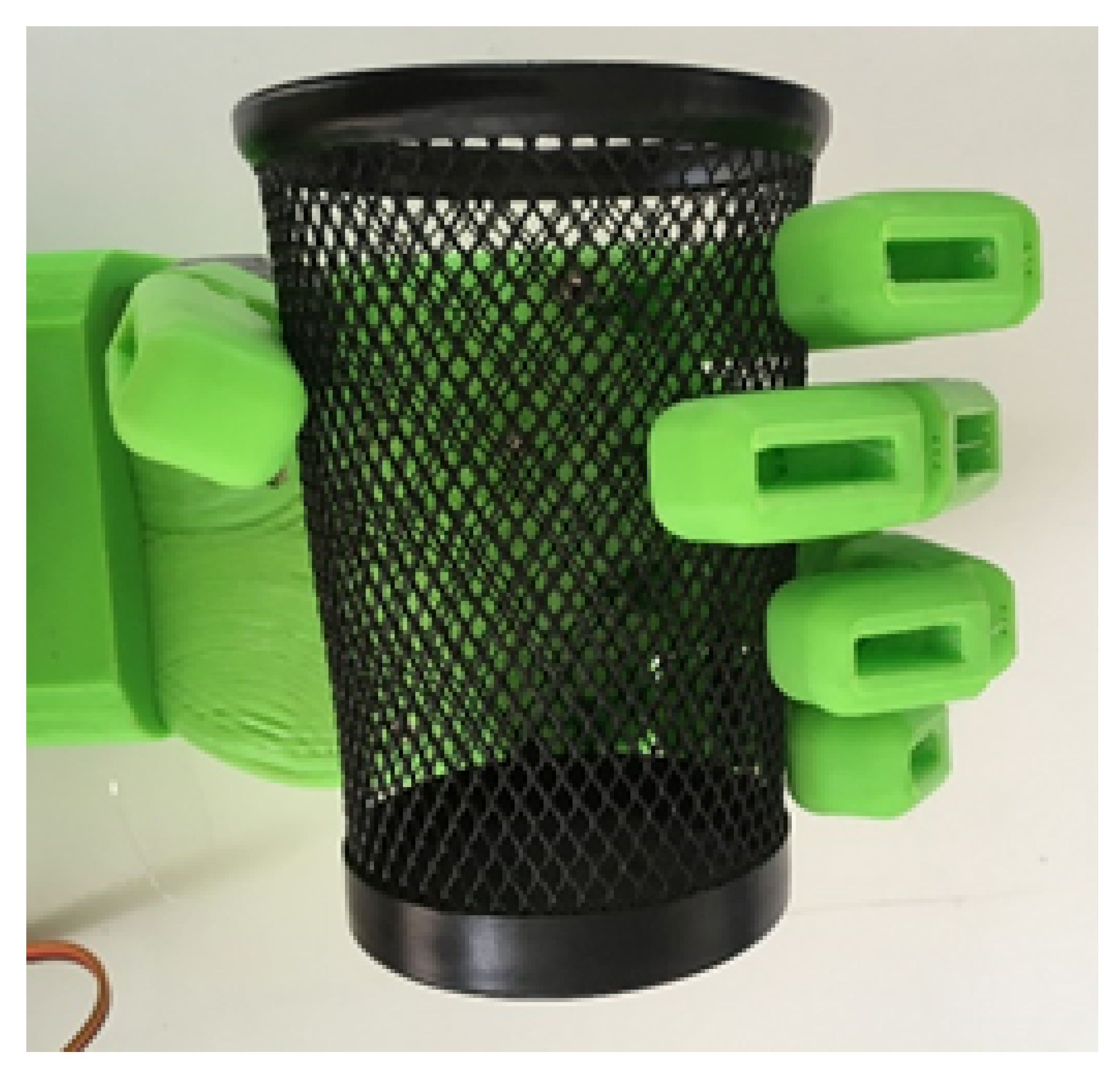
5.2. Palmar Grip
5.2.1. Digito-Palmar Grip
5.2.2. Full Palmar Grip
5.3. Central Grips
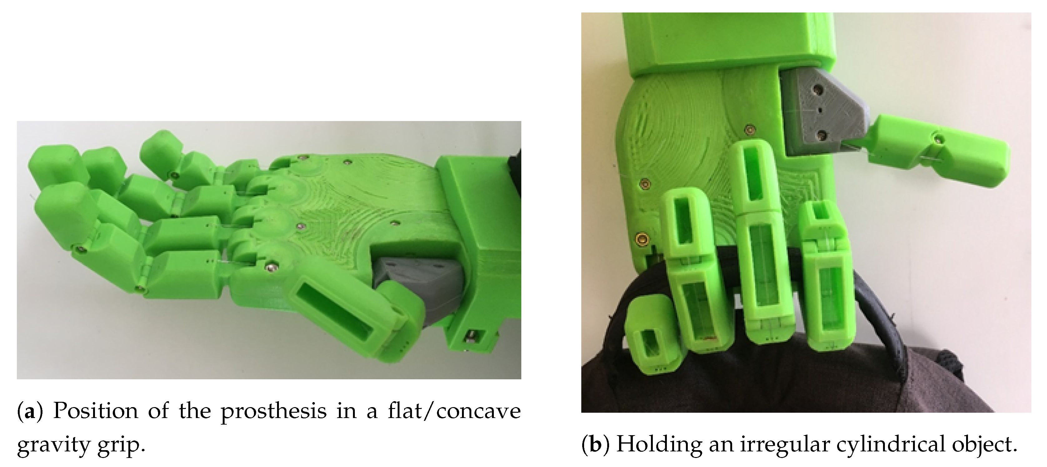
5.4. Gravity Grip
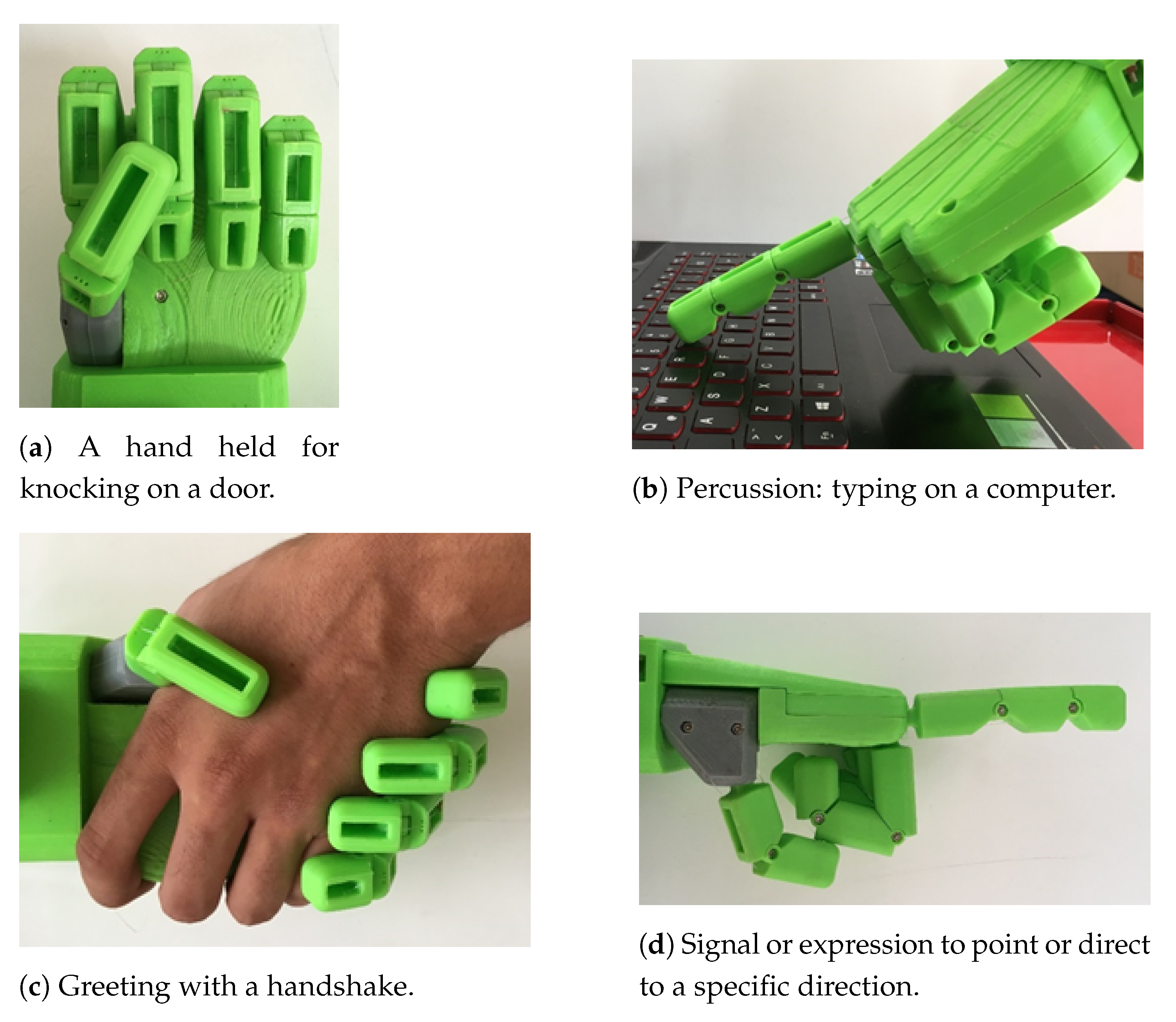
5.5. Dynamic or Active Grips
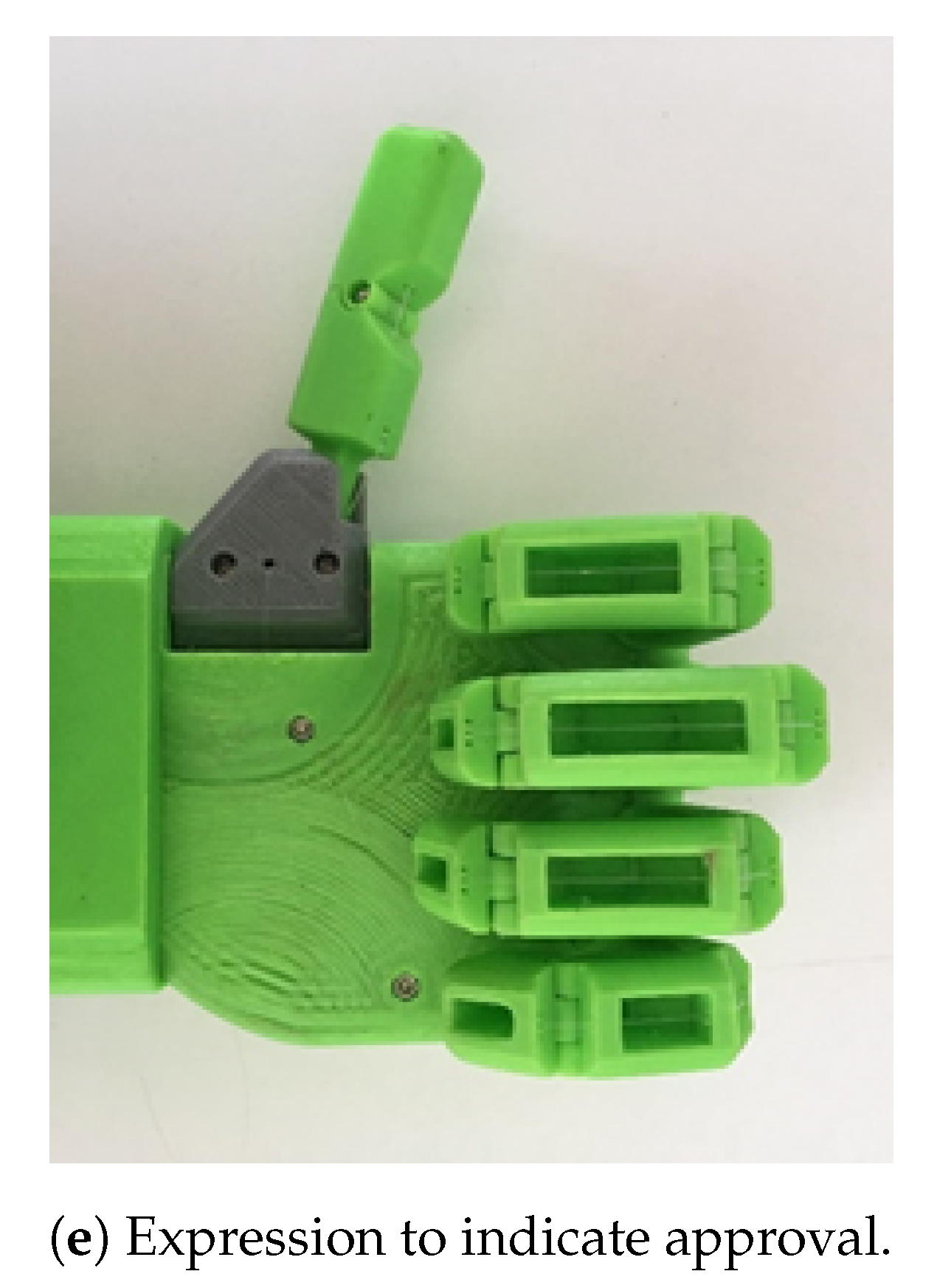
5.6. Other Grips
6. Results and Analysis
7. Conclusions
- Having distal articulation in the index, middle, annular, and little fingers. Articulation is only found in research-related prostheses, and not in commercial models.
- Sequential closure of the phalanges through a single tendon.
- Ability to conduct opposition/restitution movements, in addition to flexion/extension movements of the thumb, controlled by a single tendon.
- Opening and closing movements are performed by the same actuator.
- The lightweight design enables the construction of smaller prostheses, thereby allowing the construction of devices to be used by children.
- When worn by a child who eventually outgrows the prosthesis, it is possible to replace the prosthesis (hand) and preserve the actuation system, thus reducing replacement costs.
- Placing the motors at a distance from the hand and determining a simple way to transmit the movement to the prosthesis. This will help in the manufacturing of smaller prostheses for children, without the need to alter the design or diminish the performance due to weight restrictions.
- Although the device is easily fabricated using a 3D printer, the assembly process is laborious. Therefore, a reduction in the number of required parts is necessary in order to simplify the device’s manufacturing process.
- Verification through laboratory tests of the kinematic and dynamic capabilities, such as grip force, and speed of the prosthesis.
Author Contributions
Funding
Institutional Review Board Statement
Informed Consent Statement
Data Availability Statement
Conflicts of Interest
References
- Brito, J.; Quinde, M.; Cusco, D.; Calle, J. Estudio del estado del arte de las prótesis de mano. Ingenius 2013, 57–64. [Google Scholar] [CrossRef] [Green Version]
- Peerdeman, B.; Boere, D.; Witteveen, H.; Hermens, H.; Stramigioli, S.; Rietman, H.; Veltink, P.; Misra, S. Myoelectric forearm prostheses: State of the art from a user-centered perspective. J. Rehabil. Res. Dev. 2011, 48, 719–738. [Google Scholar] [CrossRef] [Green Version]
- Piazza, C.; Catalano, M.G.; Godfrey, S.B.; Rossi, M.; Grioli, G.; Bianchi, M.; Zhao, K.; Bicchi, A. The softhand pro-h: A hybrid body-controlled, electrically powered hand prosthesis for daily living and working. IEEE Robot. Autom. Mag. 2017, 24, 87–101. [Google Scholar] [CrossRef] [Green Version]
- Smit, G.; Bongers, R.M.; Van der Sluis, C.K.; Plettenburg, D.H. Efficiency of voluntary opening hand and hook prosthetic devices: 24 years of development. J. Rehabil. Res. Dev. 2012, 49, 523–534. [Google Scholar] [CrossRef] [Green Version]
- Datta, D.; Selvarajah, K.; Davey, N. Functional outcome of patients with proximal upper limb deficiency–Acquired and congenital. Clin. Rehabil. 2004, 18, 172–177. [Google Scholar] [CrossRef]
- Atkins, D.J.; Heard, D.C.; Donovan, W.H. Epidemiologic overview of individuals with upper-limb loss and their reported research priorities. JPO J. Prosthet. Orthot. 1996, 8, 2–11. [Google Scholar] [CrossRef]
- Singh, A. Prosthetic hand control. Int. J. Eng. Res. Appl. (IJERA) 2012, 2, 311–339. [Google Scholar]
- Belter, J.T.; Segil, J.L.; Sm, B. Mechanical design and performance specifications of anthropomorphic prosthetic hands: A review. J. Rehabil. Res. Dev. 2013, 50, 599. [Google Scholar] [CrossRef]
- Mastinu, E.; Ahlberg, J.; Lendaro, E.; Hermansson, L.; Håkansson, B.; Ortiz-Catalan, M. An alternative myoelectric pattern recognition approach for the control of hand prostheses: A case study of use in daily life by a dysmelia subject. IEEE J. Transl. Eng. Health Med. 2018, 6, 1–12. [Google Scholar] [CrossRef]
- Micera, S.; Carpaneto, J.; Raspopovic, S. Control of hand prostheses using peripheral information. IEEE Rev. Biomed. Eng. 2010, 3, 48–68. [Google Scholar] [CrossRef] [Green Version]
- Stein, R.B. Control of Powered Prostheses. Bull. Prosthet. Res. 1980, 17, 51. [Google Scholar]
- Huang, H.P.; Chen, C.Y. Development of a myoelectric discrimination system for a multi-degree prosthetic hand. In Proceedings of the 1999 IEEE International Conference on Robotics and Automation (Cat. No. 99CH36288C), Detroit, MI, USA, 10–15 May 1999; Volume 3, pp. 2392–2397. [Google Scholar]
- Balbinot, A.; Favieiro, G. A neuro-fuzzy system for characterization of arm movements. Sensors 2013, 13, 2613–2630. [Google Scholar] [CrossRef] [PubMed] [Green Version]
- Benatti, S.; Milosevic, B.; Farella, E.; Gruppioni, E.; Benini, L. A prosthetic hand body area controller based on efficient pattern recognition control strategies. Sensors 2017, 17, 869. [Google Scholar] [CrossRef] [PubMed] [Green Version]
- Resnik, L.; Klinger, S.L.; Etter, K. The DEKA Arm: Its features, functionality, and evolution during the Veterans Affairs Study to optimize the DEKA Arm. Prosthet. Orthot. Int. 2014, 38, 492–504. [Google Scholar] [CrossRef] [Green Version]
- Sanford, J.; Patterson, R.; Popa, D.O. Concurrent surface electromyography and force myography classification during times of prosthetic socket shift and user fatigue. J. Rehabil. Assist. Technol. Eng. 2017, 4, 2055668317708731. [Google Scholar] [CrossRef] [Green Version]
- Pylatiuk, C.; Schulz, S.; Döderlein, L. Results of an Internet survey of myoelectric prosthetic hand users. Prosthet. Orthot. Int. 2007, 31, 362–370. [Google Scholar] [CrossRef]
- Diment, L.E.; Thompson, M.S.; Bergmann, J.H. Three-dimensional printed upper-limb prostheses lack randomised controlled trials: A systematic review. Prosthet. Orthot. Int. 2018, 42, 7–13. [Google Scholar] [CrossRef] [PubMed] [Green Version]
- Leddy, M.T.; Belter, J.T.; Gemmell, K.D.; Dollar, A.M. Lightweight custom composite prosthetic components using an additive manufacturing-based molding technique. In Proceedings of the 2015 37th Annual International Conference of the IEEE Engineering in Medicine and Biology Society (EMBC), Milan, Italy, 25–29 August 2015; pp. 4797–4802. [Google Scholar]
- Mohammadi, A.; Lavranos, J.; Zhou, H.; Mutlu, R.; Alici, G.; Tan, Y.; Choong, P.; Oetomo, D. A practical 3D-printed soft robotic prosthetic hand with multi-articulating capabilities. PLoS ONE 2020, 15, e0232766. [Google Scholar] [CrossRef]
- Saint-Elme, E.; Larrier, M.; Kracinovich, C.; Renshaw, D.; Troy, K.; Popovic, M. Design of a biologically accurate prosthetic hand. In Proceedings of the 2017 International Symposium on Wearable Robotics and Rehabilitation (WeRob), Houston, TX, USA, 5–8 November 2017; pp. 1–2. [Google Scholar]
- Krausz, N.E.; Rorrer, R.A. Design and fabrication of a six degree-of-freedom open source hand. IEEE Trans. Neural Syst. Rehabil. Eng. 2015, 24, 562–572. [Google Scholar] [CrossRef] [PubMed]
- Ceccarelli, M.; Carbone, G.; Cafolla, D.; Wang, M. How to use 3D printing for feasibility check of mechanism design. In Advances in Robot Design and Intelligent Control; Springer: Bucharest, Romania, 2015; pp. 307–315. [Google Scholar]
- Chaparro-Rico, B.D.; Martinello, K.; Fucile, S.; Cafolla, D. User-Tailored Orthosis Design for 3D Printing with PLACTIVE: A Quick Methodology. Crystals 2021, 11, 561. [Google Scholar] [CrossRef]
- Fras, J.; Althoefer, K. Soft biomimetic prosthetic hand: Design, manufacturing and preliminary examination. In Proceedings of the 2018 IEEE/RSJ International Conference on Intelligent Robots and Systems (IROS), Madrid, Spain, 1–5 October 2018; pp. 1–6. [Google Scholar]
- Soriano-Heras, E.; Blaya-Haro, F.; Molino, C.; Del Burgo, J.M.d.A. Rapid prototyping prosthetic hand acting by a low-cost shape-memory-alloy actuator. J. Artif. Organs 2018, 21, 238–246. [Google Scholar] [CrossRef]
- Triwiyanto, T.; Pawana, I.P.A.; Hamzah, T.; Luthfiyah, S. Low-cost and open-source anthropomorphic prosthetics hand using linear actuators. Telkomnika 2020, 18, 953–960. [Google Scholar] [CrossRef]
- Belter, J.T.; Dollar, A.M. Performance characteristics of anthropomorphic prosthetic hands. In Proceedings of the 2011 IEEE International Conference on Rehabilitation Robotics, Zurich, Switzerland, 29 June–1 July 2011; pp. 1–7. [Google Scholar]
- Matrone, G.C.; Cipriani, C.; Secco, E.L.; Magenes, G.; Carrozza, M.C. Principal components analysis based control of a multi-dof underactuated prosthetic hand. J. Neuroeng. Rehabil. 2010, 7, 1–13. [Google Scholar] [CrossRef] [Green Version]
- Pons, J.L.; Rocon, E.; Ceres, R.; Reynaerts, D.; Saro, B.; Levin, S.; Van Moorleghem, W. The MANUS-HAND dextrous robotics upper limb prosthesis: Mechanical and manipulation aspects. Auton. Robot. 2004, 16, 143–163. [Google Scholar] [CrossRef]
- Massa, B.; Roccella, S.; Carrozza, M.C.; Dario, P. Design and development of an underactuated prosthetic hand. In Proceedings of the 2002 IEEE International Conference on Robotics and Automation (Cat. No. 02CH37292), Washington, DC, USA, 11–15 May 2002; Volume 4, pp. 3374–3379. [Google Scholar]
- Cordella, F.; Ciancio, A.L.; Sacchetti, R.; Davalli, A.; Cutti, A.G.; Guglielmelli, E.; Zollo, L. Literature review on needs of upper limb prosthesis users. Front. Neurosci. 2016, 10, 209. [Google Scholar] [CrossRef]
- Össur Touch Solutions. Ossur.com. Available online: http://touchbionics.com/products/active-prostheses/i-limb-ultra (accessed on 30 May 2021).
- Steeper Group. Available online: http://rslsteeper.com/ (accessed on 30 May 2021).
- Dechev, N.; Cleghorn, W.; Naumann, S. Multiple finger, passive adaptive grasp prosthetic hand. Mech. Mach. Theory 2001, 36, 1157–1173. [Google Scholar] [CrossRef]
- Gaiser, I.N.; Pylatiuk, C.; Schulz, S.; Kargov, A.; Oberle, R.; Werner, T. The FLUIDHAND III: A multifunctional prosthetic hand. JPO J. Prosthet. Orthot. 2009, 21, 91–96. [Google Scholar] [CrossRef]
- Controzzi, M.; Cipriani, C.; Carrozza, M.C. Mechatronic design of a transradial cybernetic hand. In Proceedings of the 2008 IEEE/RSJ International Conference on Intelligent Robots and Systems, Nice, France, 22–26 September 2008; pp. 576–581. [Google Scholar]
- Kamikawa, Y.; Maeno, T. Underactuated five-finger prosthetic hand inspired by grasping force distribution of humans. In Proceedings of the 2008 IEEE/RSJ International Conference on Intelligent Robots and Systems, Nice, France, 22–26 September 2008; pp. 717–722. [Google Scholar]
- Dalley, S.A.; Wiste, T.E.; Withrow, T.J.; Goldfarb, M. Design of a multifunctional anthropomorphic prosthetic hand with extrinsic actuation. IEEE/ASME Trans. Mechatron. 2009, 14, 699–706. [Google Scholar] [CrossRef]
- Weir, R.; Sensinger, J.W.; Kutz, M. Design of artificial arms and hands for prosthetic applications. Biomed. Eng. Des. Handb. 2009, 2, 537–598. [Google Scholar]
- Cheng, M.; Jiang, L.; Ni, F.; Fan, S.; Liu, Y.; Liu, H. Design of a highly integrated underactuated finger towards prosthetic hand. In Proceedings of the 2017 IEEE International Conference on Advanced Intelligent Mechatronics (AIM), Munich, Germany, 3–7 July 2017; pp. 1035–1040. [Google Scholar]
- Catalano, M.G.; Grioli, G.; Farnioli, E.; Serio, A.; Piazza, C.; Bicchi, A. Adaptive synergies for the design and control of the Pisa/IIT SoftHand. Int. J. Robot. Res. 2014, 33, 768–782. [Google Scholar] [CrossRef] [Green Version]
- BodyParts3D/Anatomography: Select Parts and Make Embeddable Model of Your Own. Available online: https://lifesciencedb.jp/bp3d/ (accessed on 30 May 2021).
- Binvignat, O.; Almagià, A.; Lizana, P.; Olave, E. Aspectos Biométricos de la Mano de Individuos Chilenos. Int. J. Morphol. 2012, 30, 599–606. [Google Scholar] [CrossRef]
- Rouvière, H.; Delmas, A. Anatomía Humana; MASSON, SA: Paris, France, 2005. [Google Scholar]
- Kapandji, I.; Tubiana, R. The Physiology of the Joints: The Upper Limb; Number v. 1, Handspring Publishing Limited: Scotland, UK, 2019. [Google Scholar]
- Ayats, M.; Suárez, R. Diseño de una prótesis de mano adaptable al crecimiento. Actas de las XXXVIII Jornadas de Automática. Available online: https://digibuo.uniovi.es/dspace/bitstream/handle/10651/46849/ActasJA2017_MAyatsetal.pdf?sequence=1 (accessed on 5 July 2020).


| Name | Weight (gr) | Actuation Time (s) | Number of Actuators | Actuator Type | Movements | Manufacturing |
|---|---|---|---|---|---|---|
| TBM Hand (1999) [35] | 280 | 4–5 | 1 | DC Motor | Adaptive grip coupled movement of the five fingers. | Complex, made of T6 aluminum. |
| RTR II (2002) [31] | 350 | 1 | 2 | DC Motor | Thumb abduction and adduction, can perform flexion in two of the ramaining fingers. | * |
| FluidHand III [36] | 400 | * | 6 | One pump and five valves | The movement of each finger is not described, only five achievable positions are indicated | Complex, mainly due to the pump |
| Smarthand [37] | 520 | 1.5 | 4 | DC motor | Thumb controlled by two motors with flexion/extension and opposition movements. The index finger is controlled by another motor and the rest of the fingers (middle, annular and little finger) are differentially controlled by the fourth motor. | Complex, requires machining for non-back-drivable actuation unit |
| Keio Hand [38] | 730 | 1 | 1 | Ultrasonic motor | The thumb can only perform a grasping movement (flexion), the remaining fingers can be flexed and extended. | manufacture requires complex aluminum machining. |
| Vanderbilt Hand [39] | 580 | 0.5–1 | 5 | DC motor mounted in the forearm | Opposition and flexion of the thumb and independent flexion of fingers. | Simple, additive manufacturing |
| SoftHand ProH [3] | 520 | * | 1 | 1 motor and 1 manually operated lever | flexion/extension of the fingers | * |
| Mechanism | Description | Figure |
|---|---|---|
| Mobile Pulleys [31,42] | When tension (T) is applied on the lower cable, the force at T1 and T2 have the same magnitude, and both upper ends move simultaneously. Once the finger connected to cable T1 touches an object, tension T1 increases and the movement is fully transmitted to T2. | 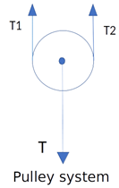 |
| Mechanical Differential [31] | This mechanism has traditionally been used in vehicles to allow wheels on the same axle to rotate at different speeds while turning a corner. The differential mechanism allows the rotation to be transmitted to the output axle that has a lower load. | 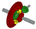 |
| Springs [35] | On this system, the actuator moves a rigid block which is connected to the fingers through springs. Once a finger D1 encounters an object, the rigid block, and thus the finger (D2), can move further due to the spring’s compression. | 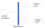 |
| Oleohydraulics [36] | In an oil hydraulic system, the pump is responsible for generating the movement of the fluid, in turn the fluid moves through the lowest resistance path, therefore when the actuator (1 ) collides with an object, the fluid will flow towards the second actuator (2). |  |
| Levers [38] | This system contains a lever capable of moving and pivoting at the point where the actuator contacts the rigid block. When the finger D1 strikes an object, the lever pivots and transmits the movement to finger D2. The relative distances from the pivot to the finger create different gripping forces for each finger. |  |
| Thumb [mm] | Index Finger [mm] | Middle Finger [mm] | Annular Finger [mm] | Little Finger [mm] | |
|---|---|---|---|---|---|
| Distal phalanx | 42 | 51 | 55 | 45 | 37 |
| Middle phalanx | - | 31 | 36 | 32 | 23 |
| Proximal phalanx | 34 | 25 | 27 | 23 | 20 |
| Thumb | Index Finger | Middle Finger | Annular Finger | Little Finger | |
|---|---|---|---|---|---|
| Relaxed extension | 60 | 0 | 0 | 0 | 0 |
| Distal phalanx flexion amplitude | 90 | 70 | 70 | 70 | 70 |
| Middle phalanx flexion amplitude | - | 110 | 110 | 110 | 110 |
| Proximal phalanx flexion amplitude | 60 | 90 | 90 | 90 | 90 |
| Opposition-reposition amplitude | 90 | - | - | - | - |
| Number of Actuators | ||||||||
|---|---|---|---|---|---|---|---|---|
| 1 | 2 | 3 | 4 | 5 | 6 | |||
| Terminal opposition term-pulpezoid | Si * | Si * | Si * | Si * | Si * | Si * | ||
| Subterminal or thumb opposition | Si * | Si * | Si * | Si * | Si * | Si * | ||
| By subterminolateral opposition or lateral pulpex | No | No | No | Si | No | Si | ||
| Bidigital grips | Interdigital latero-lateral | No | No | No | No | No | No | |
| Tridigital | Si ** | Si ** | Si | Si | Si | Si | ||
| Tetradigital | Si ** | Si ** | Si | Si | Si | Si | ||
| Digital grips | Pluridigital grips | Pentadigital | Si ** | Si ** | Si | Si | Si | Si |
| Digitopalmar grips | Si ** | Si ** | Si | Si | Si | Si | ||
| Cylindrical | Si ** | Si ** | Si | Si | Si | Si | ||
| palm grips | Full palmar grip | Spherical | Si ** | Si ** | Si | Si | Si | Si |
| Centered or directional grips | No | No | Si | Si | Si | Si | ||
| Finger | Little, Middle, and Annular | Index and Thumb |
|---|---|---|
| Quantity | 1 | 2 |
| Servomotor model | LH2018M | MG996R |
| Stall torque kgf · cm at 6V | 20 | 11 |
| Running current A | - | 0.9 |
| Stall Current A | - | 2.5 |
| Speed at 6V degrees/seg | 315 | 430 |
Publisher’s Note: MDPI stays neutral with regard to jurisdictional claims in published maps and institutional affiliations. |
© 2021 by the authors. Licensee MDPI, Basel, Switzerland. This article is an open access article distributed under the terms and conditions of the Creative Commons Attribution (CC BY) license (https://creativecommons.org/licenses/by/4.0/).
Share and Cite
Estay, D.; Basoalto, A.; Ardila, J.; Cerda, M.; Barraza, R. Development and Implementation of an Anthropomorphic Underactuated Prosthesis with Adaptive Grip. Machines 2021, 9, 209. https://doi.org/10.3390/machines9100209
Estay D, Basoalto A, Ardila J, Cerda M, Barraza R. Development and Implementation of an Anthropomorphic Underactuated Prosthesis with Adaptive Grip. Machines. 2021; 9(10):209. https://doi.org/10.3390/machines9100209
Chicago/Turabian StyleEstay, Danilo, Alvaro Basoalto, Jorge Ardila, Matías Cerda, and Rodrigo Barraza. 2021. "Development and Implementation of an Anthropomorphic Underactuated Prosthesis with Adaptive Grip" Machines 9, no. 10: 209. https://doi.org/10.3390/machines9100209
APA StyleEstay, D., Basoalto, A., Ardila, J., Cerda, M., & Barraza, R. (2021). Development and Implementation of an Anthropomorphic Underactuated Prosthesis with Adaptive Grip. Machines, 9(10), 209. https://doi.org/10.3390/machines9100209