Abstract
Biaxial mechanical testing gained increased importance for characterization of materials that present anisotropic behavior and/or different responses when subjected to tensile and compression loadings. In this work, a new biaxial testing machine was developed. The various systems and components were designed, manufactured, assembled, and assessed. Uniaxial tensile tests were performed to validate the device, showing results consistent with those obtained on a universal testing machine. Finally, biaxial tensile tests were also performed on polypropylene cruciform specimens. The results revealed high precision levels, thus showing the potential of this new machine.
1. Introduction
In a highly competitive industry, it is essential to always be one step ahead of competition. Therefore, there is an enormous need to develop profitable products. The deep knowledge about a material is necessary to optimize its use, leading to the tightening of safety margins and to waste minimization [1]. Materials, depending on their application, can be subjected to different loadings, such as tensile, compression, and shear. These may arise individually or combined.
The most common way to characterize a material is through uniaxial tests [2]. When the material is isotropic, only a few uniaxial tests are necessary to fully characterize it within the scope of material behavior models, such as the von Mises yield criterion for metals. When the mechanical behavior of the material is quite complex, uniaxial tests are not enough to properly characterize it. For instance, polymers behave differently under tensile and compression loadings [3].
Thus, multiaxial tests make it possible to obtain a wider knowledge of the mechanical behavior of a material [1]. However, these present the disadvantage of being more complex to perform and analyze. Thus, biaxial tests present a balance between the significance and complexity of the results. Recently, the mechanical behavior of materials under biaxial stress has acquired great importance, both practical and theoretical [4]. This is valid for both static and dynamic loading cases, the latter being particularly interesting for high frequency multiaxial fatigue testing [5] and also for strain rate dependent materials.
There are different types of biaxial tests, which can be divided into two categories: tests with a single loading system and tests using two or more independent loading systems [6]. In the first category, the biaxial stress ratio depends on the specimen geometry and/or the loading fixture configuration, whereas in the second category, it depends on the magnitudes of the applied loads [7]. Examples of the first category are bending tests on cantilever beams, anticlastic bending tests of flat plates, bulge tests, and tests using special fixtures [7]. Bulge tests are performed at very high pressures, resulting in necking and fracture, being used to determine the formability limits. However, the high pressure leads to uncontrollable neck and crack propagation, because of the force-controlled nature of the experiment [1].
Regarding independent loading systems, examples are a round bar under torsion combined with bending, thin-wall tubes subjected to a combination of tension/compression and torsion or internal/external pressure, and cruciform specimens under in-plane biaxial loading [7]. The thin-wall tube is the most popular one, allowing any constant load ratio [7,8,9,10,11]. However, it also has some disadvantages, such as the existence of non-negligible radial stress gradients depending on the tube thickness and the applied load, the fact that thin-wall tubes are more complex to manufacture for some materials, the elastic instability when subjected to circumferential, axial compression, or torsion loads, and the anisotropic properties of tubes and plate materials being often different, among others [7,12,13].
Biaxial tests are desirable for inducing plane stress. To carry out a valid plane biaxial test for a cruciform specimen, it is necessary to guarantee a uniform stress/strain state at the specimen center, which has to be fixed in space during testing, and failure has to occur in the test zone and not in the uniaxially loaded arms [14,15]. To fulfill such requirements, the influence of some parameters needs to be properly handled, such as the thickness of the biaxially loaded test zone in relation to the thickness of the uniaxially loaded arms, the radius of the corner fillet at the intersection of the arms, and the presence and dimension of slits across the arms [1,7,14,16]. Additionally, to guarantee the null displacement of the central point, it is necessary to have four movable arms, with both endpoints in the same axis moving at the same speed in opposite directions.
In 1967, Shiratori and Ikegami [17] developed an automated biaxial testing machine with two hydraulic actuators and loading capacity of 50 kN. Makinde et al. [18] developed a machine with two servo-hydraulic actuators per axis, capable of delivering the same load in both axes. Two electro-hydraulic closed-loop channels that independently controlled the two axes made it possible to fix the central point of the specimen. The load in each direction was measured using four load cells.
Later, Boehler et al. [19] developed a screw-driven biaxial testing machine based on the one designed in Makinde et al. [18]. The machine was equipped with TMD-governors that enable constant speeds to be maintained on DC-motors, together with a closed-loop control system using optical incremental encoders. It also has four AC-motors that work independently from each other and allow fast positioning. Overall, it consists of four double-acting screw-driven pistons, two in each direction, rigidly supported on an octagonal vertical frame. In each direction, the maximum load is about 100 kN in tension and compression. It has an unobstructed working area of 900 × 900 mm2 that enables tests on specimens with a size up to 500 × 500 mm2. Therefore, the vertical installation of the octagonal frame which surrounds the specimen ensures excellent accessibility from both sides to the working area, which facilitates the mounting and observations throughout a test. The described mechanical concept and servo-control system allow cruciform specimens to be subjected to large strain biaxial tensile and compressive tests without kinematic incompatibilities. However, the dead weight of the gripping system causes a prestress in the cross-sectional area of the specimen.
Kuwabara et al. [20] presented a machine similar to the one developed by Makinde et al. [18]. It uses opposing hydraulic cylinders connected to common hydraulic lines and is thus subjected to the same hydraulic pressure. The hydraulic pressure of each pair of cylinders is servo-controlled independently, and a load cell is included in each loading direction. The displacement of opposing hydraulic cylinders are equalized using a pantograph-type link mechanism, maintaining the center of the cruciform specimen always at the center of the testing apparatus. This linking mechanism was effective in reducing the production cost.
In this work, the development of a new biaxial testing machine is presented, intended for polymer testing at quasi-static rates. The main characteristics desired were robustness, reduced size (compact), ease of use, precision, and, at the same time, low cost. The steps of development and its several mechanical, electrical, and control systems are described here.
2. Materials and Methods
This section describes the mechanical, electrical, and control systems developed for the new biaxial testing machine. They allowed the capacity of 10 kN to be delivered reliably and robustly. Overall, this equipment consists of the machine structure, electrical panel, data acquisition, and control systems (Figure 1).
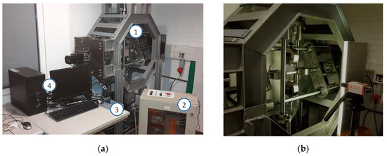
Figure 1.
Biaxial testing machine: (a) (1) machine structure; (2) electrical panel; (3) acquisition system; and (4) computer for control; (b) Uniaxial tensile testing (horizontal axis) showing the video-extensometer system.
2.1. Mechanical Design
2.1.1. Main Structure
Figure 2 presents the main structure of the biaxial testing machine. It has a support base, inspired in the biaxial machine from Boehler et al. [19]. This arrangement makes it possible to easily position the specimen and the video-extensometer apparatus. The supporting base also makes it easier to transport. The structure was built by welding, which resulted in minor deformations. These were considered during the project, and thus, corrected by adjusting the final alignment.
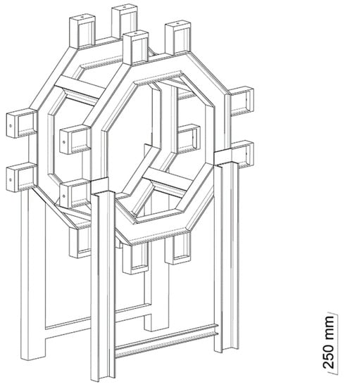
Figure 2.
Main structure.
2.1.2. Alignment
The alignment between lateral plates is fundamental, not just for the assembly, but also to guarantee proper working conditions, including the alignment of the axes. The lateral supports were welded, having the screwed plates with guides between each other (Figure 3). Therefore, it was necessary to find a way to align and block it in space, which influenced the geometry of the lateral plates.
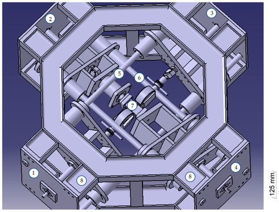
Figure 3.
Equipment overview for compressive testing: (1–4) lateral plates; (5,6) axis; (7) sample for compressive test; (8) lateral support.
Considering that the gripping system would be in the center of the crosshead, the guides would block the specimen center. Instead, the methodology adopted to avoid this was to arrange the side plates and the crossheads diagonally (Figure 4). While providing a greater field of view for the specimen, it also reduces the deviation caused by perpendicular forces from crossheads on the other axis.
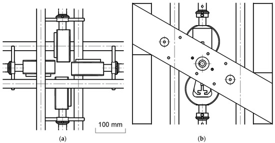
Figure 4.
Intermediate solution for the alignment of the plates: (a) Frontal view—detail of the visibility and accessibility to the specimen area; (b) Lateral view—lateral plate.
Once the specimen was sufficiently visible, it was necessary to align the lateral plates between them. However, the plates represented in Figure 3 cannot be properly aligned since they only have two points of contact with the structure. When modifying the geometry of the plates, four contact points could be obtained that allowed the adjustment in any direction. The adjustment is quite simple, using a screw to force the plate to approach the structure and two others that force it in the opposite direction, blocking it in any desired position (Figure 5a). The positions of the guides make it possible to have a field of view of the specimen of 300 × 300 mm2. The plate has a wider zone to provide space for the bearing, as well as a series of threaded holes for subsequent motor placement (Figure 5b).
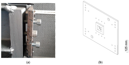
Figure 5.
Final lateral plate: (a) Position adjusting system (no scale); (b) Isometric view.
2.1.3. Guidance System
A 30 mm diameter chrome-plated bar CK45 was used for the guides, having the necessary stiffness to avoid significant bending and, at the same time, low roughness. Bearings are commonly used to guarantee low friction in linear guidance systems. Two NBS KB3068 linear bearings per crosshead were employed to ensure accurately guided movements. The radial loads resulting from the crosshead weights and the manufacturer’s datasheet point to a long lifespan. However, the rupture of a cruciform specimen can cause imbalances that may generate much higher radial loads in the bearings. Thus, the apparent oversizing provides strengthened confidence regarding the movement of the crossheads, avoiding the occurrence of gaps and other issues caused by repeated use of the machine.
2.1.4. Transmission System
A precise system must be developed to carry out quasi-static testing (e.g., 1 mm/min) with loads up to 10 kN. A ball screw linear actuator with nut system was employed to transform the rotation imposed by the motors in linear motion. The choice of using a ball screw instead of a lead screw is justified by the superior transmission efficiency (90% versus 30%). Since this is an efficient system, the weight of the crossheads is enough to cause rotation, which was a decisive factor in the selection of the electrical motors (Section 2.2). The wearing is also much lower with the ball screw.
The NBS VFU3205 ball screw was employed, with an outer diameter of 32 mm and a lead of 5 mm. It has an expected service life of 106 rotations for a uniform axial load of 14.5 kN. On the other end of the spindle, a bearing responsible for axially fixing it without restricting its rotation was employed. It also supports axial loads during the testing. It is an angular contact double row ball bearing, reference 3205B.2RSR.TVH from FAG. It supports dynamic axial loads up to 15 kN and static ones up to 19 kN (neglecting radial loads). A KM 5 lock nut was used to fix it. Rigid coupling was used for the connection with the motor, through a keyway–key connection as depicted in Figure 6.
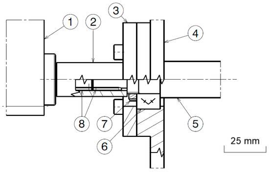
Figure 6.
Drawing of the transmission system: (1) motor; (2) rigid coupling; (3) cover plate; (4) lateral plate; (5) spindle; (6) bearing; (7) nut; (8) keys.
2.1.5. Crossheads
The crossheads are movable parts of the structures, being supported by the guidance system and fixed to the nuts of the ball screws. These move along the two axes of the machine. Its geometry was strongly influenced by the transmission, gripping, and guidance systems. Once the spindle is immobile, it is in the way of the gripping system when the crosshead is forced back. To solve this issue, the crossheads have two bars: an anterior one where the nut is fixed, and a posterior one with the gripping and acquisition systems.
The distance between these two bars is extremely important since it is the course available, influenced by the accessories of each crosshead—e.g., having or not a load cell—resulting in crossheads with different distances between plates. This is configuration has the advantage of allowing greater distances between bearings. These plates needed to be perfectly aligned, and the whole set had to be robust. A hollow bar was used, placing the bearings inside it, and its exterior aligned and kept fixed relative to the plates. Additionally, two reinforcement plates were added to minimize the maximum deflection of the set. Figure 7 depicts the crosshead and its constituents.
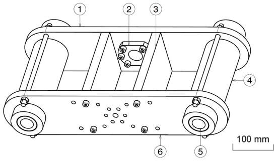
Figure 7.
Crosshead drawing: (1) anterior plate; (2) nut; (3) reinforcement plate; (4) hollow bar; (5) ball bearing; (6) posterior plate.
Figure 8 shows the adjustment stops included in the design. Once these collide with the crosshead, the ball screw nut system becomes inoperable. In the opposite direction, when it collides with the posterior plate, the motor does not have enough torque, leaving the rotor blocked.
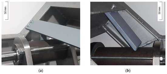
Figure 8.
Adjustment stops for crossheads: (a) with load cell; (b) without load cell.
2.1.6. Gripping System
Two pairs of 5 kN wedge grips from Shimadzu were employed. To make the positioning of cruciform specimens easier, an unusual configuration was adopted. By rotating the grips, the openings are on opposite sides, but the specimen can be placed by rotation of the straps (Figure 9).
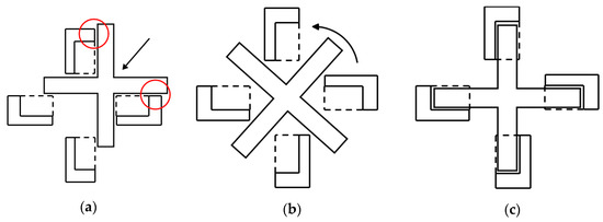
Figure 9.
Illustration of the placement of a cruciform specimen: (a) typical configuration; (b) adopted configuration; (c) cruciform specimen ready for testing (no scale).
2.1.7. Load Cell Horizontal Support
The load cells used (Section 2.2) are exclusively for compression and tensile loads. Due to the vertical arrangement of the machine, the horizontal axis load cell is subjected to a momentum caused by the weight of the grip. Thus, the cell could be loaded in a direction to which it was not designed for and this could negatively influence the results. Therefore, an additional structure was created (Figure 10), which gives side support to the load cell but still allowing movement in the horizontal direction. In this support, a PAP 3025-P10 plain bearing was used since the loads are low and the movements are reduced, resulting in minimal wear.
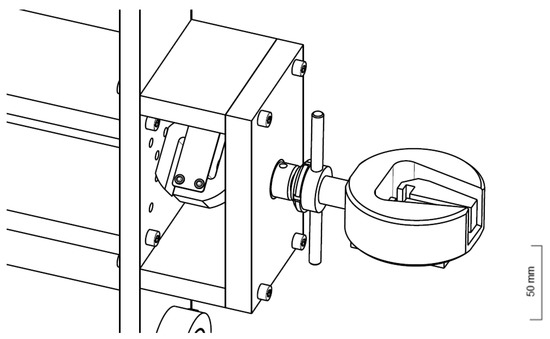
Figure 10.
Illustration of the grip support.
2.1.8. Compression Test System
To make it possible to carry out tensile–compression and compression–compression biaxial tests, a particular system was designed. First, it is necessary to remove the grips, coupling parts, and the support of the load cell in the specific axis. In the crosshead, where the load cell is placed, a new support structure was designed, again due to the weight of some parts, but also to avoid compressive deformations during testing. Figure 11 illustrates the compression test arrangement, where the force is transmitted to the load cell thanks to a rod.
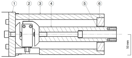
Figure 11.
Compression configuration: (1) posterior plate; (2) load cell; (3) outer tube; (4) rod; (5) plain bearing; (6) cover plate.
In the other crosshead, only a rod is necessary to make it sturdy, avoiding bending or another form of deformation. Both rods are threaded on the ends to couple testing components, which varies according to the specimen and its dimensions. Both configurations are presented in Figure 12.
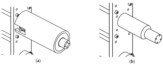
Figure 12.
Compression system: (a) with a load cell; (b) without load cell (no scale).
2.2. Electrical Design, Control, and Data Acquisition
The electrical project of the machine here developed consists of a series of connected components essential for properly carrying out the experiments, such as moving the crossheads and data acquisition from the load cells. Figure 13 presents the schematics of the main electrical connections.
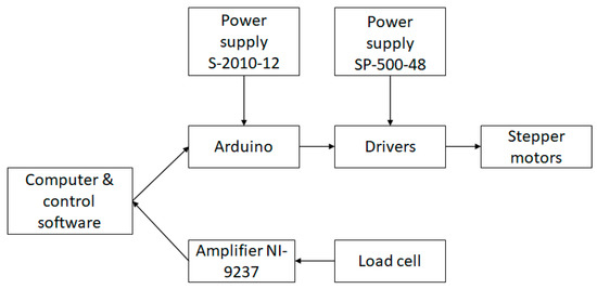
Figure 13.
Schematics of the main electrical connections.
Almost all the electrical components are in a portable electrical panel (with proper shielding and labeling), connected to the motors through a 24-pin connector. Stepper motors were used due to the necessity of precise control of the testing speed and higher torque at low speeds. The 34HS38-4004D-SG20 stepper motor was used. It is a high torque motor, including a spur type planetary gearbox with a gear ratio of 20:1, which satisfies the necessity of precise control, especially at low speeds with higher torque.
High-performance MA860H microstepping drivers were used to power and control the stepper motor. This driver amplifies the signal from the microcontroller, which controls the motor speed. With four of these drivers, it is possible to control each motor individually. In the end, the testing speed is defined by the capacity of the microcontroller, the motor gearbox gear ratio, and the spindle lead, which resulted in 400 impulses/rot.
On the other hand, the current for the motors was based on the maximum force expected for testing. The machine was designed for 10 kN, but to guarantee a safety margin, a higher load was expected for the crossheads. The value was obtained considering the motor torque of 4.5 N.m at 4 A, the gearbox efficiency of 70%, and the equation given by the ball screw manufacturer
where Mm is the motor torque, Pmax is the maximum axial load, L is the spindle lead, and η is the efficiency of the transmission.
Mm = Pmax × L/(6820 × η),
The power supply of the various circuits is done through three power sources, two SP-500-48 power supplies for the drivers and the one S-201-12 power supply for the microcontroller and the remaining control circuit. Also, an auxiliary power circuit was employed to reduce the ATmega328 microcontroller power need. Screw shielding was used to improve the connections to the Arduino Uno Rev3.
Two S-type tensile/compression 10 kN load cells were used, one in each axis. The power supply of the load cells and the data acquisition are performed thanks to the National Instruments simultaneous bridge module NI-9237, together with the NI cDAQ-9178 CompactDAQ USB chassis. For signal processing, the module uses a combination of analog and digital filters, obtaining a correct representation of the in-band signals, while rejecting the out-of-band signals. The three main filters used are: passband, stopband, and alias-free bandwidth. The first filter only lets a range of frequencies pass, attenuating the remaining frequencies. The remaining two avoid and eliminate the phenomenon described by aliasing: when a signal is sampled at a frequency lower than twice the highest frequency of the signal, sampling can confuse a signal of a higher frequency into a lower frequency signal, leading to distortions between the real and sampling [21]. With all the motors and drivers working, the maximum noise influence is around ±2 N.
The control project focused mainly on the Arduino for both manual automatic controls. LabVIEW was used for both data acquisition and automatic control, incorporating all in the same program. A sampling rate of 2.5 kHz was defined for data acquisition. The load cells are calibrated considering the weight of the parts that might influence the measurements. In the end, it is possible to control each one of the four motors independently, to define the type of load (tensile/compression) and the speed of the test, all in automatic or manual mode.
2.3. Experimental Testing
The load cells were calibrated using a universal testing machine, the Shimadzu 50 kN-AG. The calibration was performed already using the hardware and software of the biaxial testing machine. It was performed both types of loading. A regression analysis was performed obtaining R2 values of almost 1. The linear regression equations for the x-axis (horizontal) and y-axis (vertical) were, respectively, F = 4.86875 U + 0.10492 and F = 4.88140 U − 0.12813, where F is the load (kN) and U is the normalized voltage (mV/V). The automatic zero load calibration, useful to eliminate the influence of the weight of the grip, showed that the constants in the regression lines should be ignored and only the slope should be considered for calibration.
One of the limitations found was the impossibility of placing a calibration table for each cell in the software. Since the slopes of the regression lines are almost independent of the load cells, an average between the two slopes giving F = 4.875075 U was used to create the final calibration table. This approximation leads to an error of 0.13% between the actual value of each cell and the read value. Considering that the load cell will not be subjected to more than 5 kN, the error for such a load corresponds approximately to a 6.5 N difference between the real and the read values, and considering the 0.25 N error of the calibration in the universal testing machine, this an acceptable approach.
In this work, the sample deformations were obtained with a video extensometer, the Messphysik ME-46NG. The dot tracking and displacement measurement was carried out with the DotMeas software, with micrometrical precision and acquisition frequencies of 3 Hz.
Experimental tests were performed to validate the present machine systems here developed by comparison with results of uni-axial tests conducted in a Shimadzu 50 kN-AG universal testing machine. It was decided to use polypropylene (PP), chosen for its low cost, good machinability, and low rigidity, which makes it easier to measure the deformations in a relatively small central area, where the specimen is supposed to fail.
The specimens were obtained from a 5 mm PP sheet thick plate, using a bandsaw and the CNC Machining Center Mikron VCE500 (HAAS VF-0). The specimens for uniaxial tensile testing (Figure 14a) followed the guidelines of the ISO 527-2 standard [22]. The cruciform specimens (Figure 14b) resulted from a finite element based study described in [23]. These specimens have reduced thickness near the central area in order to promote failure in this region.
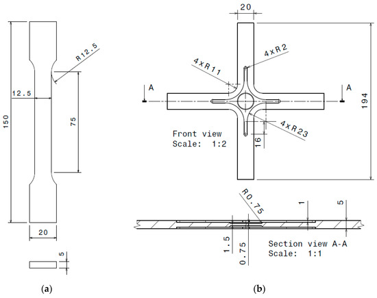
Figure 14.
Specimens for tensile loading: (a) uniaxial; (b) biaxial.
To start the experimental campaign, first, it is necessary to ensure the correct position of the grips, guaranteeing the specimen’s centering. In addition, it is necessary to mark the test pieces with the dots to be tracked by the video-extensometer. To center the grips, a block with a drawn cross was used. By placing the block supported on the lower grip, it is possible to move the crossheads individually, until all the grips align their center with the lines, thus ensuring that all grips are at the same distance and properly aligned (Figure 15). After alignment, the crossheads must always move together until the beginning of the test, maintaining the alignment and thus the symmetrical testing conditions.
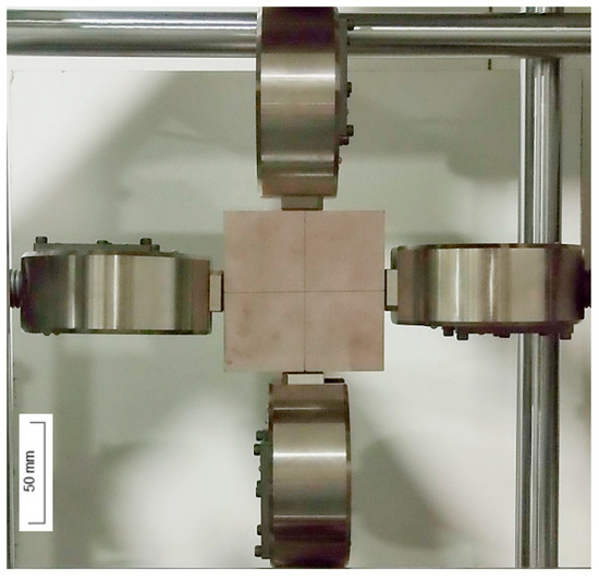
Figure 15.
Gripping system alignment.
2.3.1. Uniaxial Tests
For video-extensometer analysis, 40 μm points were marked in the samples, one in the center and two equally distanced from it by 10 mm. The real distance was measured in an optical microscope—Mitutoyo TM, at a resolution of 0.001 mm—to calibrate it in the DotMeas software. Pre-loads were carefully avoided, and thus no deformation was caused to the samples during their placement in the grips. The uniaxial tensile tests were carried at a speed of 10 mm/min and the criterion used to stop testing was necking observation. Four tests were carried out, two per each axis.
2.3.2. Biaxial Tests
Similar to the specimens for uniaxial tensile testing, points were also marked to measure deformations. Two additional points for the second loading direction when performing biaxial tensile tests. The same procedure and conditions were employed for marking, measuring, calibration, and pre-load elimination. Lines were also marked on the test piece arms for alignment, ensuring that the specimen was centered. The biaxial tensile tests were carried out at a speed of 10 mm/min, equal on both axes, and the criterion used to stop testing was necking observation.
3. Results
3.1. Uniaxial Tests
The measured load-displacement data were used to compute the stress-strain behavior from the uniaxial tests as
σ = P/A0,
ε = (L − L0)/L0,
In the first stage, the uniaxial tests allowed to confirm the equivalence between the x-axis and y-axis systems (Figure 16). The differences between the various curves that can be explained by the natural dispersion of material properties. Figure 17 compares the results with those obtained from tests in a universal testing machine. There is good agreement between the results of both machines, thus validating the loading and measurement systems of the biaxial machine.
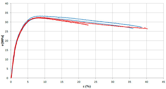
Figure 16.
Stress–strain curves obtained from uniaxial tensile tests performed in the biaxial testing machine on MEB (horizontal axis—blue curves; vertical axis—red curves).
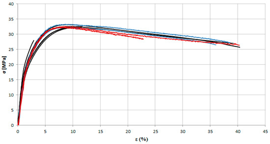
Figure 17.
Stress–strain curves obtained from uniaxial tensile tests performed in the biaxial testing machine on MEB ((horizontal axis—blue curves; vertical axis—red curves) compared with the ones performed in a universal testing machine (in black).
Figure 18 shows a specimen after testing, which presents a uniform distribution in the gauge zone (lighter area), but also a necking region formed at the end of the test.

Figure 18.
Uniaxial tensile test sample after testing.
3.2. Biaxial Tests
The results of the biaxial tensile tests showed good repeatability (Figure 19), and there was a great similarity between the load–displacement curves of the two axes.
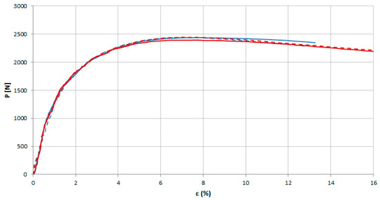
Figure 19.
Load–displacement response measured in the biaxial tensile tests (solid curves—horizontal axis; dashed curves—vertical axis).
However, after the tests it was seen that failure did not start in the measurement zone, in the center, but actually in the areas around it, where there were stress concentrations (Figure 20). This shows that the chosen specimen geometry is not well-suited for determining the stress–strain curves up to failure. Nevertheless, as expected from the biaxial load combination, imposed failure took place at a 45° orientation relative to the loading axes.
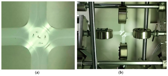
Figure 20.
Cruciform sample after the biaxial tensile testing: (a) before failure; (b) at failure (no scale).
4. Conclusions
The present work presents the development of a new biaxial testing machine, describing in detail its design, assembly, control system, and data acquisition. The solution here presented is quite interesting for testing polymers, being robust, precise, and low cost. Moreover, the preparation and execution of the tests are quite simple. The load cell data acquisition system and the video extensometer were successfully combined, providing the necessary data to characterize the materials. Good repeatability and consistency between the horizontal and vertical axes were observed, as shown by comparison with uniaxial tensile tests performed on a universal testing machine. The results of biaxial tensile tests reinforced confidence in the developed machine.
Although the main goals were achieved, future improvements can be made to this biaxial testing machine. For instance, at the mechanical level, the development of a fixed support system for easy placement of the video-extensometer apparatus. At the software level, the automatic combination of data from the load cells and the video-extensometer, as well as the use of digital image correlation. The use of electrical limit switches would also increase safety by preventing damage to the components and by simply being a simpler solution than the installed mechanical limit switches.
Author Contributions
Conceptualization, A.B.P., F.A.O.F., A.B.d.M., and J.M.; Data curation, A.B.P.; Formal analysis, A.B.P., F.A.O.F., and A.B.d.M.; Funding acquisition, A.B.P.; Investigation, A.B.P., F.A.O.F., A.B.d.M., and J.M.; Methodology, A.B.P., F.A.O.F., A.B.d.M., and J.M.; Project administration, A.B.P. and A.B.d.M.; Resources, A.B.P.; Software, J.M.; Supervision, A.B.P. and A.B.d.M.; Validation, A.B.P., F.A.O.F., A.B.d.M., and J.M.; Visualization, A.B.P. and J.M.; Writing—original draft, A.B.P., F.A.O.F., A.B.d.M., and J.M.; Writing—review and editing, A.B.P., F.A.O.F., and A.B.d.M. All authors have read and agreed to the published version of the manuscript.
Funding
This work was supported by the projects UIDB/00481/2020 and UIDP/00481/2020 - FCT - Fundação para a Ciencia e a Tecnologia; and CENTRO-01-0145-FEDER-022083 - Centro Portugal Regional Operational Programme (Centro2020), under the PORTUGAL 2020 Partnership Agreement, through the European Regional Development Fund.
Acknowledgments
The researchers, under grant (CEECIND/01192/2017), would like to acknowledge the Fundação para a Ciência e a Tecnologia (FCT).
Conflicts of Interest
The authors declare no conflict of interest.
References
- Quaak, G. Biaxial Testing of Sheet Metal: An Experimental-Numerical Analysis. 2008. Available online: https://www.semanticscholar.org/paper/Biaxial-Testing-of-Sheet-Metal-%3A-An-Analysis-Quaak/6386ee720de5598d75750dbbbcc96b807f76e244 (accessed on 28 June 2020).
- Hannon, A.; Tiernan, P. A review of planar biaxial tensile test systems for sheet metal. J. Mater. Process. Technol. 2008, 198, 1–13. [Google Scholar] [CrossRef]
- Altenbach, H.; Tushtev, K. A new static failure criterion for isotropic polymers. Mech. Compos. Mater. 2001, 37, 475–482. [Google Scholar] [CrossRef]
- Vezér, S.; Major, Z. Development of an in Plane Biaxial Test Setup for Monotonic and Cyclic Tests. In Proceedings of the 25th Danubia-Adria Symposium on Advances in Experimental Mechanics, Český Krumlov, Czech Republic, 24–27 September 2008. [Google Scholar]
- Costa, P.; Nwawe, R.; Soares, H.; Reis, L.; Freitas, M.; Chen, Y.; Montalvão, D. Review of multiaxial testing for very high cycle fatigue: From ‘conventional’ to ultrasonic machines. Machines 2020, 8, 25. [Google Scholar] [CrossRef]
- Zouani, A.; Bui-Quoc, T.; Bernard, M. Cyclic stress-strain data analysis under biaxial tensile stress state. Exp. Mech. 1999, 39, 92–102. [Google Scholar] [CrossRef]
- Smits, A.; Van Hemelrijck, D.; Philippidis, T.P.; Cardon, A. Design of a cruciform specimen for biaxial testing of fibre reinforced composite laminates. Compos. Sci. Technol. 2006, 66, 964–975. [Google Scholar] [CrossRef]
- Andrews, J.M.H.; Ellison, E.G. A testing rig for cycling at high biaxial strains. J. Strain Anal. 1973, 8, 168–175. [Google Scholar] [CrossRef]
- Lefebvre, D.; Chebl, C.; Thibodeau, L.; Khazzari, E. A high-strain biaxial-testing rig for thin-walled tubes under axial load and pressure. Exp. Mech. 1983, 23, 384–392. [Google Scholar] [CrossRef]
- Ellyin, F.; Wolodko, J. Testing facilities for multiaxial loading of tubular specimens. In Multiaxial Fatigue and Deformation Testing Techniques; ASTM International: West Conshohocken, PA, USA, 2009; pp. 7–24. [Google Scholar]
- Found, M.; Fernando, U.; Miller, K. Requirements of a new multiaxial fatigue testing facility. In Multiaxial Fatigue; ASTM International: West Conshohocken, PA, USA, 2008; pp. 11–23. [Google Scholar]
- Dawicke, D.S.; Pollock, W.D. Biaxial Testing of 2219-T87 Aluminum Alloy Using Cruciform Specimens; National Aeronautics and Space Administration, Langley Research Center: Hampton, VA, USA, 1997. [Google Scholar]
- Smith, E.; Pascoe, K. Biaxial fatigue of a glass-fibre reinforced composite. Part 1: Fatigue and fracture behaviour. In Biaxial and Multiaxial Fatigue; Brown, M., Miller, K., Eds.; Mechanical Engineering Publications: London, UK, 1989; pp. 367–396. [Google Scholar]
- Van Hemelrijck, D.; Makris, A.; Ramault, C.; Lamkanfi, E.; Van Paepegem, W.; Lecompte, D. Biaxial testing of fibre-reinforced composite laminates. Proc. Inst. Mech. Eng. Part L J. Mater. Des. Appl. 2008, 222, 231–239. [Google Scholar] [CrossRef]
- Welsh, J.S.; Adams, D.F. An experimental investigation of the biaxial strength of IM6/3501-6 carbon/epoxy cross-ply laminates using cruciform specimens. Compos. Part A Appl. Sci. Manuf. 2002, 33, 829–839. [Google Scholar] [CrossRef]
- Kelly, D.A. Problems in creep testing under biaxial stress systems. J. Strain Anal. Eng. Des. 1976, 11, 1–6. [Google Scholar] [CrossRef]
- Shiratori, E.; Ikegami, K. A new biaxial tension testing machine with flat specimens. J. Soc. Mater. Sci. Jpn. 1967, 16, 433–439. [Google Scholar] [CrossRef]
- Makinde, A.; Thibodeau, L.; Neale, K.W. Development of an apparatus for biaxial testing using cruciform specimens. Exp. Mech. 1992, 32, 138–144. [Google Scholar] [CrossRef]
- Boehler, J.P.; Demmerle, S.; Koss, S. A new direct biaxial testing machine for anisotropic materials. Exp. Mech. 1994, 34, 1–9. [Google Scholar] [CrossRef]
- Kuwabara, T.; Ikeda, S.; Kuroda, K. Measurement and analysis of differential work hardening in cold-rolled steel sheet under biaxial tension. J. Mater. Process. Technol. 1998, 80, 517–523. [Google Scholar] [CrossRef]
- Morris, A.S. Measurement and Instrumentation Principles, 3rd ed.; Butterworth-Heinemann: Oxford, UK, 2001; ISBN 9780080496481. [Google Scholar]
- ISO. ISO 527-2:2012-Plastics—Determination of Tensile Properties—Part 2: Test Conditions for Moulding and Extrusion Plastics; International Organization for Standardization: Geneva, Switzerland, 2012. [Google Scholar]
- Batista, P. Conceção de Amostras Para Ensaios Biaxiais; Universidade de Aveiro: Aveiro, Portugal, 2016. [Google Scholar]
© 2020 by the authors. Licensee MDPI, Basel, Switzerland. This article is an open access article distributed under the terms and conditions of the Creative Commons Attribution (CC BY) license (http://creativecommons.org/licenses/by/4.0/).