Abstract
The rising mobility demand of today’s society leads to an increasing strain of noise and pollutant emissions on people and the environment. An increasing environmental awareness and the scarcity of fossil fuels are increasingly placing alternative-powered vehicles in the focus of politics, research and development. Electric vehicles represent a promising solution to this problem. The electric machine represents a design control lever for the optimization of the electric powertrain with regard to efficiency, power, weight and size. Therefore, accurate and realistic machine design tools for the design of electric machines are becoming increasingly important. In this paper, the authors present an electric machine design tool for electric machines using MATLAB® in order to enable an automated machine design. The electric machine design tool is published under an LGPL open source license.
1. Introduction
Today, mobility is a basis for the functioning of our economy. Rising energy prices, environmental awareness and dependency on oil and gas exporting countries increase the urge to develop new energy sources and the desire to improve existing transportation systems. The predicted shortage of fossil fuels and stricter emission regulations are motivating the development of more efficient and “cleaner” vehicles that consume less and, at best, no fossil fuel at all [1]. To achieve this goal, both hybrid and full electric vehicles are part of extensive research and development in the field of vehicle technology. Electric vehicles enable a locally emission-free driving experience and offer an immediate torque density and good efficiency over the entire speed range [1].
The idea behind the electric powertrain is about as old as the combustion engine, i.e., approx. 150 years [2]. In the early days of the automobiles, both types of powertrains were deployed. However, the combustion engine, whose technology and efficiency have been progressively optimized for vehicle applications, has become more established in the last century. The electric powertrain was, rather, used in the industrial sector and mainly in stationary applications. Accordingly, optimizations for electric powertrains have been made primarily with regard to stationary industrial applications over the past 150 years. However, the requirements of the dynamic applications in the automotive sector differ significantly from the stationary requirements. Accordingly, major development and optimization work was and is necessary on the essential components of electric machines, transmissions and power electronics in order to adjust their potential to their combustion counterpart [2].
The electric machine, inverter and the battery form the central components of an electric powertrain. However, greater attention is generally focused on the optimization of the electric machine, since its efficiency is normally lower than that of the other components when considering a wide range of operating points [3].
Therefore, the focus of this work is the design process and the subsequent analysis of electric machines. However, the aim is to develop a holistic model for the design and analysis of permanent magnet synchronous machines (PMSM) and induction machines (IM), in order to calculate initial design topologies, characteristic maps and enable the efficiency analyses of different machine concepts at an early design stage. The authors therefore present an open source electric machine design tool using MATLAB®, which enables an initial calculation of the main electric machine properties, e.g., dimensions, electrical and magnetic characteristics, using few input parameters. The main focus of the presented tool is the estimation and analysis of the geometry and boundary conditions of a desired electric machine and the calculation of its efficiency. This is beneficial in order to estimate the efficiency potential of an electric machine in an early design phase. Another aim of this work is the improvement and critical revision of the calculation and design process of electric machines, as well as the investigation of improvement potentials in the conventional machine design process, especially with regard to the stator and winding design. The tool was created in accordance to previous work at the authors institute [4,5].
2. State of the Art
The aim of the state of the art is to provide the basic knowledge required for the methodology and the presented electric machine design tool.
2.1. Machine Topology
The electric machine transforms electrical energy into mechanical energy and transmits it to the drive shaft, which in turn is mechanically connected to the gearbox or directly to the wheels [6]. The development of electric machines for different application use cases has led to the creation of a variety of different machine types or topologies. In general, all known electric machine types can be used in electric vehicles. The decision for a particular machine depends on the expected driving profile. Further criteria, such as costs, manufacturability, maintainability, recyclability, lifetime, power density, efficiency and material selection need to be taken into account when selecting the respective machine [7]. Due to its comparatively low efficiency and the use of carbon brushes, the classic DC machine no longer has significant use in powertrains today [7] and three-phase machines are mainly implemented, e.g., the IM and PMSM [8]. Therefore, only these two types of machines are considered in the context of this work and the machine design tool.
The main difference between the PMSM and the IM is the composition of the rotor and the associated operating characteristics [9]. For the IM, the generation of the torque is based on the so-called Lorentz force or magnetic induction [10]. The IM follows an operational characteristic, where the rotor must rotate asynchronously to the impressed magnetic field to generate torque. The IM therefore has a so-called slip that is determined by the ratio of synchronous speed, i.e., the speed of the rotating stator field, to the rotors speed [10]. As a result of the changing magnetic field, Faraday’s law of induction in turn induces a voltage in the rotor windings [9,11,12]. The greater the difference between the speed of the stators rotating field and the rotor speed, the faster the change in the magnetic field and the greater the induction voltage Eh [10].
Apart from the rotor, the design of an IM is similar to that of a PMSM. The stator basically consists of a stack of metal sheets and a winding which is wound into the evenly distributed stator slots along the rotors bore diameter [13]. For the rotor of the induction machine, two design structures are mainly considered—the slip ring and the squirrel-cage rotor [12,14].
A PMSM, like the IM, mainly consists of the active parts, e.g., stator and rotor components, as well as passive parts such as a cooling system and an inverter. The stator is constructed similarly to that of the IM. However, the rotor contains magnets, the arrangement of which significantly influence the electrical characteristics of the machine, instead of the windings and slots as in the IM [15]. The rotor design of a PMSM can be roughly divided into surface-mounted permanent magnet synchronous machine (SPMSM), where the permanent magnets (PM) are glued to the surface of the rotor and the interior permanent magnet synchronous machine (IPMSM), in which the magnets are buried or inserted into the rotor [15]. The SPMSM is relatively inexpensive, due to a simple manufacturing process [15]. However, eddy currents can heat up the magnets and lead to an irreversible demagnetization [16]. In addition, the surface magnets need to be bandaged to the surface of the rotor, in order to prevent them from becoming detached at high rotational speeds [17]. This problem can be solved by using IPMSM, since the magnets are fixed within the rotor and the centrifugal forces are absorbed by the overlying laminated core. Additionally, the laminated core protects the magnets from mechanical damage and eddy currents [13].
The advantages of IMs with a squirrel-cage rotor are mainly its robust and simple design compared to the generally higher efficiencies of the PMSMs at high torques and in partial load operation at low speeds [18]. With regard to energy consumption, IMs are particularly suitable when high speed ranges are required. This is the case if the vehicle is frequently used for longer overland or motorway journeys. The efficiency distribution of the PMSM makes it particularly suitable for low speed operation and thus for vehicles intended for urban traffic. The synchronous machine is, compared to the induction machine, the more expensive alternative. The system costs of the PMSM are about 20% higher than those of the IM [19]. However, it must be taken into account that a higher efficiency can also reduce the battery size and thus the largest cost factor. Therefore, even if the machine alone has higher costs, it can still offer significant cost advantages in the overall system due to its energy efficiency [19].
With regard to the maximum efficiency of a machine, it should be noted that it does not extend over the entire speed/torque range of an efficiency diagram, but rather, depending on the type of machine, consists of a range of higher and lower efficiencies. The losses that occur in the respective speed/torque ranges depend on numerous machine parameters, and are mainly determined by the type of machine. For example, a PMSM usually shows high efficiencies at speeds close to the rated speed and higher torque areas. For the IM, the range of minimum losses is mainly located in the higher speed ranges [19,20]. Tesla Motors, for example, uses the opposing advantages and disadvantages and the different high efficiency areas of the IM and PMSM by implementing an all-wheel drive variant for the Model 3, whereas a type of PMSM is used for rear-wheel drive and an IM for the front-wheel drive. At high rotational speeds, the IM is mainly used due to its high efficiency in this range, whereas at lower speeds, the PMSM takes over the propulsion. This makes use of specific driving situations and thus effectively increases the range by using the respective range of high efficiency for both machines [19].
2.2. Loss Types of Electric Machines
An electric machine converts electrical energy into mechanical energy and vice versa, which causes losses in the machine [15]. This leads to an increasing temperature in the machine, which must be eliminated by the cooling system of the machine [15,21]. For industrial machines, the most common approach is to design the machine so that its maximum efficiency and thus minimal losses are located at the stationary rated operating point. Regarding a machine for a battery electric vehicle (BEV), the total energy balance of a load profile (driving cycle) is of interest [19]. Accordingly, for the dynamic operation of a BEV, a machine with the highest possible efficiency in the relevant speed-torque range is desired.
The different loss types of electric machines can be roughly divided into load-dependent, e.g., copper losses and load-independent losses, e.g., iron and mechanical losses [14]. The additional losses can be divided into both load-independent and load-dependent losses [17].
Machine losses can also be differentiated according to the area of the electric machine they occur in. The stator accounts for the largest proportion of total losses due to the high occurrence of copper, iron and additional losses. Due to the excitation of the PMs in a PMSM, the copper losses do not occur in the rotor.
The copper losses Pv,w mainly occur in the conductors of the windings as a result of the current flow [10] and are therefore also called winding or current heat losses [17]. The copper losses are significantly involved in the thermal behavior of the electric machine, leading to irreversible ageing processes, e.g., damaging of the insulation [22]. For a symmetrical three-phase winding, they can be calculated by multiplying the resistance R and the square of the phase current IStr [17]:
In addition to copper losses, the iron losses of a machine account for a significant proportion of the total losses and are composed of hysteresis losses and eddy current losses [15,22], due to a time-varying magnetic field in the laminated sheets [10]. Different model approaches by Steinmetz, Jordan and Bertotti have analyzed methods for the calculation of iron losses, which differ significantly in their accuracy and complexity of parameterization [23]. In this analysis, the approach by Jordan was chosen, which contemplates the separation of iron losses into static hysteresis losses ph and dynamic eddy current losses pw [23] as in Equation (2). This enables a more precise description of the loss behavior in soft magnetic materials [24].
The mechanical losses are mainly caused by bearings and air-friction losses [17] and are proportional to the friction surface and the square of the circumferential speed v of the rotor as in Equation (3) [6,23]. Whereas the length of the rotor is represented by lRotor, the rotor outer diameter by da and the correction factor krb is taken from experimental results [17].
The additional losses are caused by harmonics in the air-gap field, by harmonics of the feeding current and by current displacement in the windings [17]. Since the analytical calculation of additional losses is difficult, for the purpose of an initial rough estimate and due to the low proportion of the total losses, the additional losses can therefore be neglected [17].
2.3. Efficiency Diagrams
By varying the stator frequency f1 and the stator voltage U1 by means of the inverter, the machine can be operated at variable speeds [15,25]. The resulting speed-torque characteristic diagram is exemplarily shown in Figure 1.
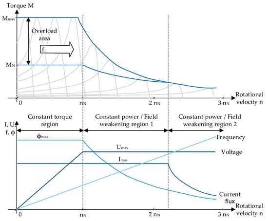
Figure 1.
Speed-torque characteristic diagram of an IM with variable speed operation [15,20].
With increasing rotor speed, the torque increases and reaches its maximum achievable torque MK at tilting slip s = sK [10]. The value of the tilting torque MK is usually two to three times greater than that of the nominal torque MN [6,25,26]. The value of the nominal torque MN is determined by the permanent thermal load capacity of the machine [26,27]. The nominal speed nN and the nominal torque MN are available in the linearly decreasing part of the characteristic efficiency diagram. The motor operation of an electric machine is therefore always to the right of the tilting torque MK [25].
The nominal torque MN is available up to the nominal speed nN. This range is called the constant torque region. In this region, the mechanical power increases linearly with constant nominal torque and increasing rotational speed until the nominal rotational speed is reached and therefore the maximum voltage of the inverter Umax.
In order to increase the rotational speed beyond the nominal speed, the magnetic flux ϕ needs to be reduced in order to keep the inverter voltage constant. The reduction of the flux in turn reduces the torque, whereas the power remains constant. This region is called the field weakening region. Field weakening represents a certain difficulty for PMSM, because the field of the PM cannot be weakened directly [7]. Therefore, an opposing field must be generated which weakens the field of the PMs. This field should not exceed a specific magnitude, so that the PMs are not irreversibly demagnetized [11].
2.4. Conventional Machine Design
The conventional machine design process is made up of a variety of design steps that follow a fixed sequence, see Figure 2. They are mostly based on literature, as well as empirical values or expert knowledge of design engineers and result in high safety margins. This significantly impacts the performance and efficiency, and leads to higher overall costs as well as an overdesign of the electric machine [28].
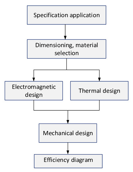
Figure 2.
Overview of conventional electric machine design [29].
In a first step, the specification of the application, e.g., vehicles for urban, long-distance or racing use-cases and so on, is established. Here, the main vehicle and machine parameters such as maximum velocity, aerodynamic properties and henceforth the necessary torque and rotational speed of the electric machine, are determined. In the next step, the main dimensions such as the outer diameter of the stator and rotor are determined, as well as the main materials can be selected. In the next step, the electromagnetic and thermal design are determined based on the previously established requirements. The electromagnetic design mainly encloses the winding design, the calculation of the possible magnetic circuits, as well as the excitation and power distribution [17]. In the thermal design, the implemented machine design is examined in regard to the critical temperature of the components. This is followed by the mechanical design, used to examine whether, for example, the bearings of the machine are designed sufficiently.
For further literature on the topic of the conventional design process of electric machines, the authors refer to the corresponding standard literature [10,11,14,16,17,22,29].
There are several disadvantages in regard to the conventional design approach of electric machines. Due to the sequential approach, the solution space of the possible parameter combinations is reduced in each step of the design process by selecting a combination from the solution-space. Therefore, a respective local optimum is defined, which is based predominantly on experiences of the developer. Due to the early reduction of the solution space, the combination which represents a possible global optimum is possibly eliminated prematurely from the solution-space. The resulting limitations can lead to a general oversizing of the machine.
Therefore, the authors introduce a novel design model in order to dissolve the conventional fixed sequential design and enable a holistic consideration of all machine parameter combinations. The aim is to combine known literature values and processes with a new stator and winding design as well as an interactive interface to enable the user to design an electric machine and the respective efficiency diagrams using few input parameters.
3. Methodology and Model Structure
This section describes the development of an automated design and analysis tool for IMs and PMSMs by the authors. In a first step, the modeling process that serves as the basis for the tool is explained. Then, a short comparison of the simulation of IMs and PMSMs is made to investigate the potential synergy effects in the calculations. Afterwards, the program structure and the user interface of the tool are presented.
3.1. Overall Model Structure
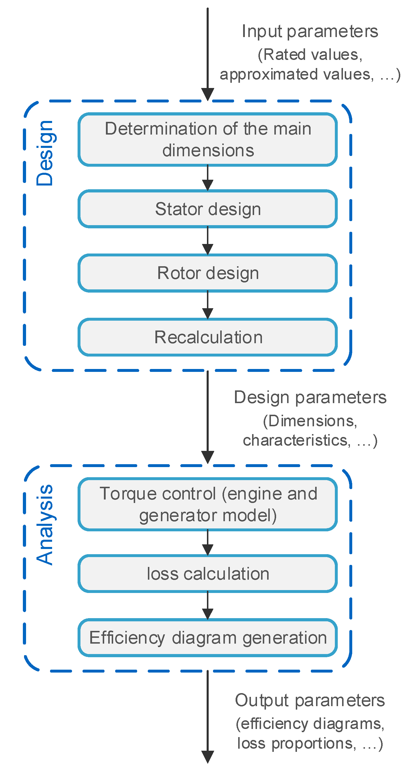
For the automated simulation of the machine design in the presented model, the calculation process of an IM and PMSM will be combined in a holistic model. Since the basic procedures for the design and analysis of an IM is somewhat comparable to the procedure of a PMSM, the procedures for the model are roughly combined for the design and analysis of a PMSM or IM. This is shown in Figure 3.
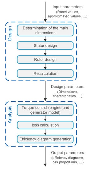
Figure 3.
Overview of implemented electric machine design model.
The implemented tool consists of the two model sections design and analysis. Based on the given input parameters, the main dimensions are determined in a first step of the design model. Once they are determined, the stator and rotor layout can be designed. The design parameters are then passed to the analysis model and the currents and voltages are calculated using a motor and generator model for operating points in the valid operating range. Finally, the losses are determined and the efficiency diagram can be generated.
The overall structure of the implemented design model is based on the conventional design process featured in literature. However, on the one hand, the overall stator design process was optimized in order to enable the calculation of the global optimum for the stator design in regard to the overall requirements. This process is further explained and published by the authors in [30,31,32]. On the other hand, the fixed sequential design process of the conventional machine design is improved by implementing iterative loops within each step of the design process.
3.2. Comparison of the Simulation Process of PMSM and IM
The aim of the comparison of the simulation process of PMSM and IM is to find synergies between the two machine types and implement them in a holistic model. For this purpose, the individual calculation steps of the design are briefly compared with each other.
3.2.1. Design
The calculation of the main dimensions is similar for both machine types. The main difference lies in the choice of approximated values, which can be found in the specified literature for specific machines [17,22].
In the stator design, there are no significant differences that directly affect the design process, because both machine types require a winding to generate the necessary rotating field. Therefore, the possibilities for the stator design optimization [30,32] can be implemented identically for both IM and PMSM. The only difference must however be taken into account in the selection of a final winding option, depending on the respective requirements. For example, in the case of an IM, a lower scattering coefficient for the harmonics due to parasitic effects is to be rated higher than in the case of a PMSM, where the harmonics are to be assessed less critically ([17], pp. 118–120).
The rotor design is fundamentally different for the two machine types. In an IM, a winding is accommodated in the rotor, which in the squirrel-cage machine consists of rods and short-circuit rings. This has to be dimensioned accordingly. In addition, the slot geometry and the magnetic circuit must be designed analogously to the stator design. With a PMSM, the PMs must be dimensioned in the rotor design and arranged accordingly in the rotor. Numerical methods are also required for the precise design and calculation of IPMSMs.
There are also differences between IMs and PMSMs with regard to the recalculation. With PMSMs, the focus is on the determination of the longitudinal and transverse axis inductances and stator resistance. In contrast, the total inductances of the stator and rotor, as well as the stator and rotor resistances are more relevant for the analysis in the IM. Additionally, the recalculation of the magnetic circuit is required to correct the geometry and determine the magnetizing current.
3.2.2. Analysis
In the case of torque control for the motor and generator model, the torque control procedures are combined to form a minimum current torque control for both machine types. The difference lies in the different system equations of the machines. In the IM, for example, currents occur due to the winding in the rotor. Additionally, the rotor rotates asynchronously to the stator rotating field. Accordingly, the optimization problem used to calculate the currents must be solved with the respective system equations depending on the type of machine.
With regard to the loss calculation, the underlying calculations between the two machine types are similar. However, the different characteristics of the loss components must be taken into account.
In summary, there are direct synergy effects between the two machine types with regard to the stator design. The stator design can therefore be implemented similarly for both machine types. For the determination of the main dimensions, the torque control and the calculation of the losses, overlaps in the calculations can be used with regard to some adjustments for the respective machine type. However, the rotor design and the recalculation are rather different, whereas no synergy effects can be exploited there.
3.3. Model Structure and Functions
Both model components contain two main functions for the calculation process of the respective machine type. The main functions are designed in such a way that the overlaps identified in the previous section can be used in the calculation steps in the form of a common code basis and only minor adjustments are necessary for the respective machine type. In addition, the procedures for the three different stator design options are combined into a uniform model structure and integrated into the two main functions. Both the design and the analysis component have separate graphical user interfaces (GUI) that guide the user through the design and analysis process and will be presented in Section 3.4 and Section 3.5.
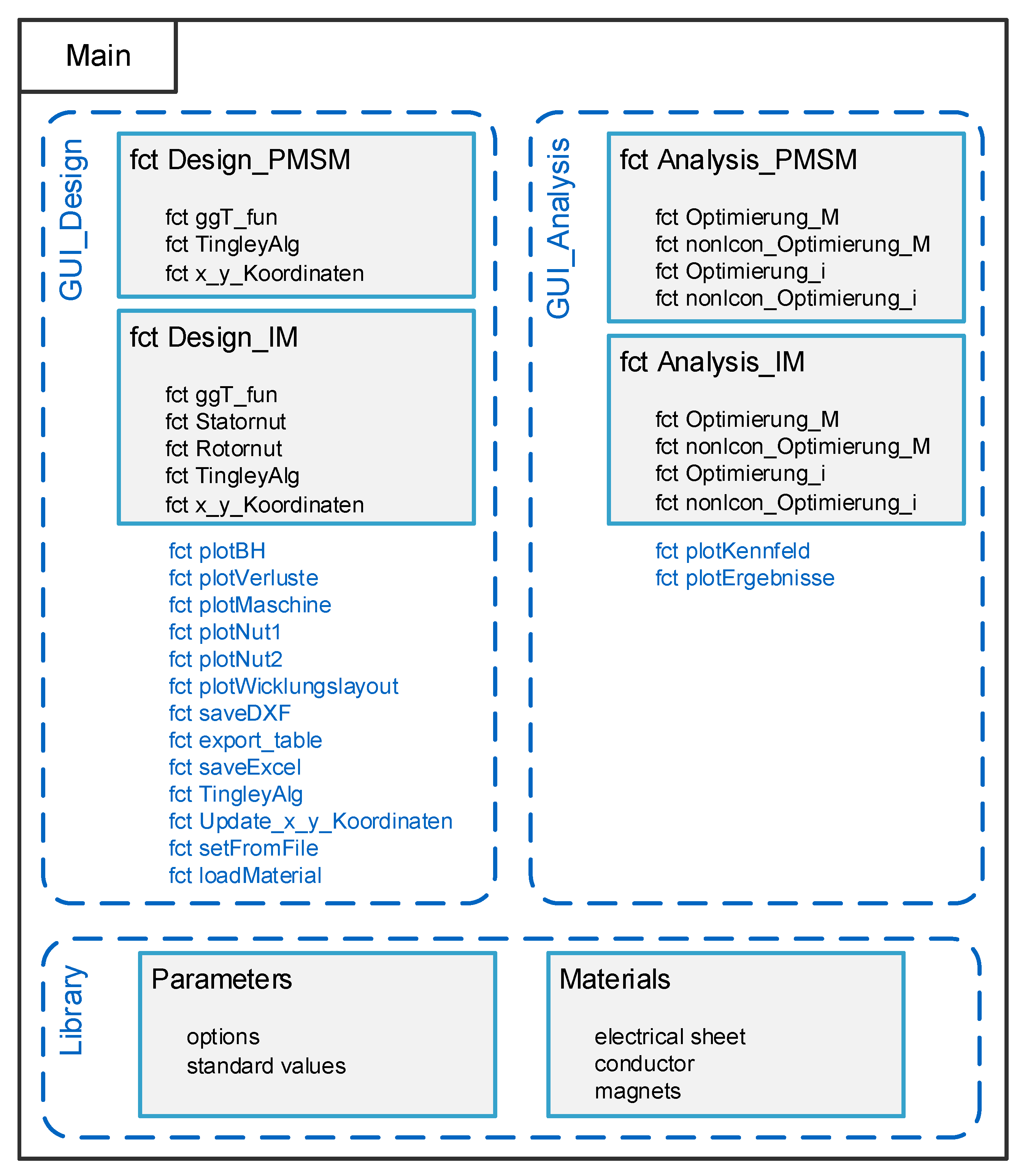
An overview of the model structure and the various functions is shown in Figure 4. The functions that are only required for the internal processes of the graphical user interface and data handling are not listed. The description and classification of the individual functions is carried out step by step in the following sections.
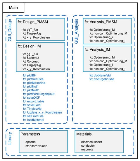
Figure 4.
Model structure and functions.
In addition to the two main components, two libraries are created that can be used by the design and analysis model component. Among other things, the reference values taken from the literature are stored in the parameters library according to the respective machine type. The characteristic values of the materials are stored in the materials library. For the electrical sheets, for example, material parameters such as the B-H and iron loss curves of the manufacturer Vacuumschmelze are integrated [33].
Further components of the implemented model are the data storage system and two interfaces. With the data storage system, the machine design can be saved at any time and continued later. It is also possible to call up an already designed machine and recalculate it with desired alterations. Another advantage is the possibility to easily save and archive the results. The interfaces are an export of geometry data to the CAD data format dxf (fct saveDXF) and an export of the design results to an Excel file (fct export_table, fct saveExcel). The CAD data can then, for example, be imported into an FEM program and used for further calculations. This is particularly relevant for the IPMSM, in order for it to be able to calculate the transverse and longitudinal axis inductances accurately.
The model is initialized by calling the script main and the graphical user interface opens in order to guide the user through the design process.
3.4. Graphical User Interface for Design
In the input tab of the design user interface, the user specifies the input parameters for the desired machine design. The user interface of the input is shown in Figure 5.
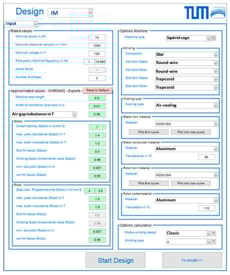
Figure 5.
Input parameters for the machine design process.
In a first step, the user selects the desired machine type. Depending on the machine type selected, the corresponding input fields required for the design are then activated in the user interface and the reference values and available options are loaded from the libraries. A dynamic access to the libraries makes it easy to adapt and expand the options and reference values, without having to make changes to the user interface.
Once the machine type has been selected, the design parameters must be entered and the machine options selected. By selecting the material-specific options, the respective material properties are loaded from the materials library (fct loadMaterial). The Plot B-H curve button and the Plot iron loss curve button can then be used to display the material properties of the electrical sheet (fct plotBH, fct plotlosses).
If required, the approximated values can be adapted to the desired requirements. The user is supported by the user interface by comparing the inputs with the validity range for the respective reference value stored in the parameter library. If the value entered exceeds or falls below the limits for minimum or maximum allowable values, the background color of the input field changes from green to red (Figure 5). The initially entered reference values represent an average standard value for each parameter, so that a first valid dimensioning is possible without further input.
With the start design button, the main function fct Design_xy of the selected machine type is initiated and the design process begins. The calculation steps described in the previous subsections are then carried out for the respective machine type.
In order to visualize the different parameter combinations, they are illustrated in the form of a radar chart, in which the criteria are listed in a comparative manner. For illustration purposes, the winding matrix of a single-layer integral-slot winding (using N1 = 36, p = 2, m = 3) is shown in Equation (4). The first line contains the groove numbers of strand A, the second line the groove numbers of strand C and the third line the groove numbers of strand B.
The winding matrix can be created from the zone plan by simply assigning the groove numbers to the strands. The function fct plotWindinglayout then visualizes the winding layout from the winding matrix. In the derivation from the Tingley plan, the columns of a strand are combined to form the winding matrix of a layer. If the winding step y1 is known, the winding matrix of a second layer can be generated. The Tingley plan is created from the winding parameters and described in the following using Meyer ([22], pp. 115–116). In the first step, a matrix is formed with (q1,n N1)/(2 p) columns and 2 p rows. Then the slot number 1 is entered in the first field of the matrix. Then, q1,n−1 fields are left empty and the next number is entered. This is repeated until the groove number N1 is reached. Using the Tingley plan, it is then possible to assign the coil sides to the grooves and the strands and to derive the winding matrix from it. Table 1 shows the Tingley plan for a single-layer integral-slot winding derived from Equation (4).

Table 1.
Tingley plan of a single-layer integral-slot winding (N1 = 36, p = 2, m = 3).
Once the design process is completed, the results tab of the design interface displays selected results and the geometry of the machine. Figure 6 shows the interface of exemplary design results.
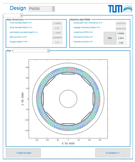
Figure 6.
Results of the design process and representation of the geometry.
In addition to the most relevant main dimensions, such as stator inner diameter or ideal length, some machine characteristics are also displayed. When visualizing the geometry, the user can choose between the overall view of the machine, the geometry of the stator slot and, if available, the geometry of the rotor slot (fct plotMachine, fct plotSlot1, fct plotSlot2). For a PMSM, further functions are activated. For example, the values of the longitudinal and transverse axis inductance and the interlinked flow of the PM can be adjusted here. This makes it possible to feed the data obtained from a FEM simulation back into the simulation tool and to improve the analytical estimation of the design process. A further function is the adaptation of the geometry of the magnets, as well as the magnet arrangement (fct Update_x_y_Coordinates). It should be noted that values for the longitudinal and transverse axis inductance and the interlinked flux of the PM from an external calculation must always be specified for the adapted geometry. These values can be determined with the exported CAD data of the adapted geometry, for example when using an FEM program. After selecting a parameter combination, the design can be continued.
In addition, the winding design offers two possible options for adjustments—the optimization option and the manual option. The user interface for the optimization option is shown in Figure 7. Here, different predetermined winding types can be selected using literature value. The winding options can then be compared in regard to specific machine parameters and their implications. For illustration purposes, a radar chart for a single-layer integral-slot winding with N1 = 36, q1 = 3, W1,Sp,rel =1 and a1 =1 was chosen in regard to the outer stator diameter D1a, the air-gap inductance Bm, the scattering coefficient σ1, the winding factor of the fundamental wave X1, the absolute error err1 and the mass of the conductor material m1.
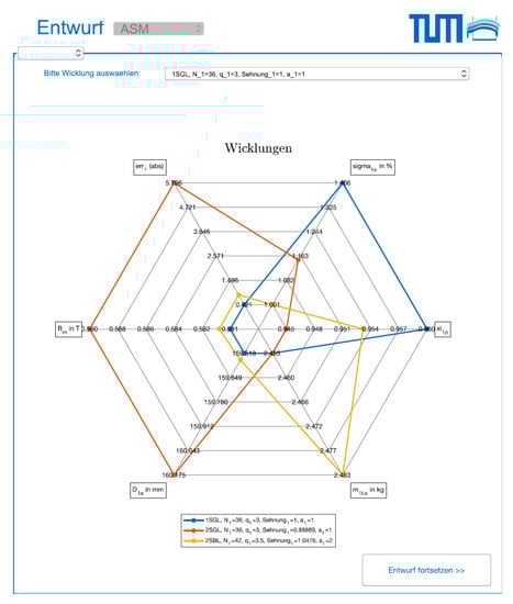
Figure 7.
Option Optimization—Comparison of windings according to certain criteria.
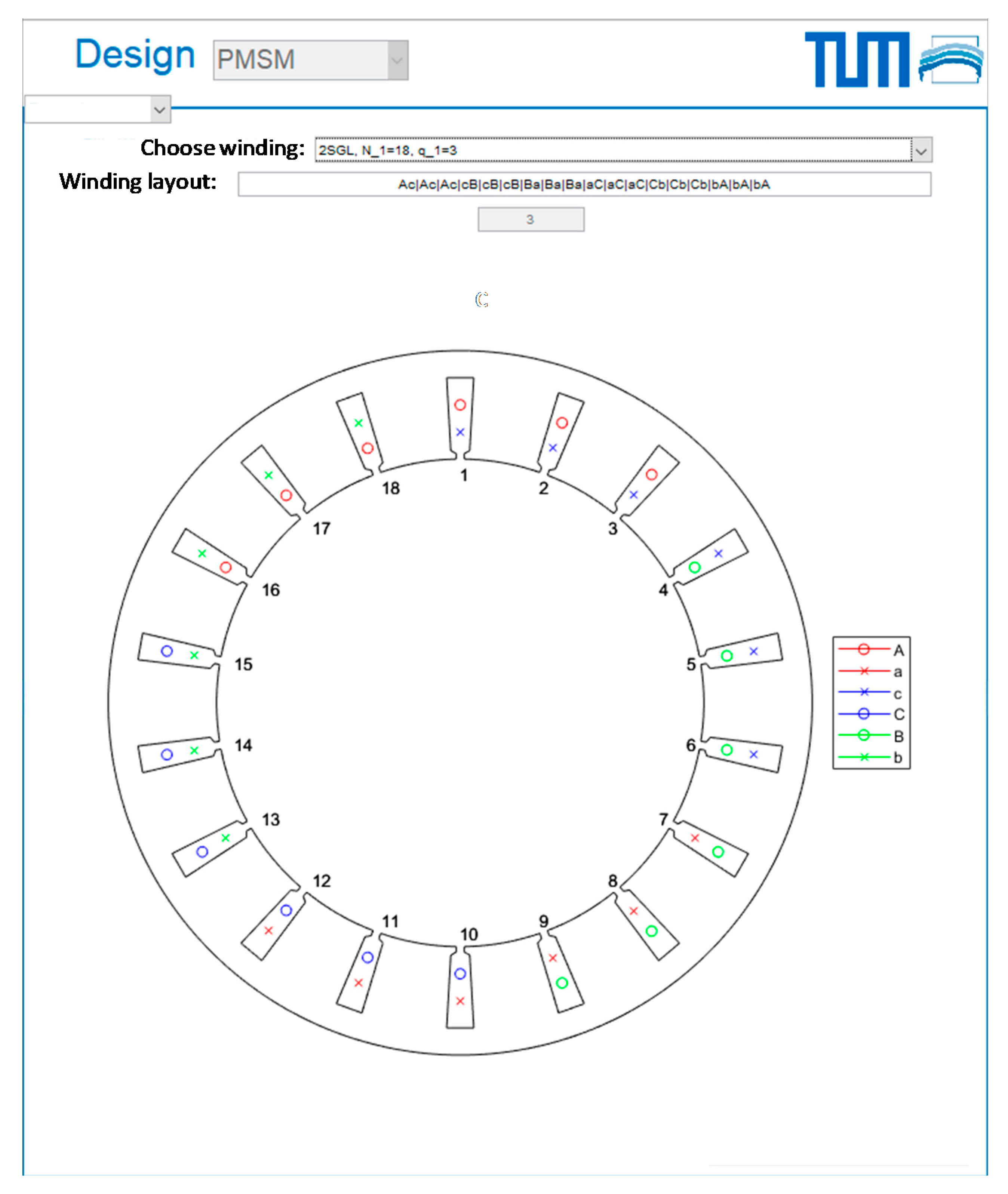
Similar to the optimization option, the manual option requires an intermediate step in the design process. In this step, the user can select one of the possible winding combinations or enter his own winding layout in the form of a zone plan. The winding layout is then visualized using a generic machine. Figure 8 shows this in the user interface. The respective denotations in this step are based on [30].
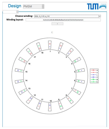
Figure 8.
Option Manual—Input or selection of a winding for the design.
When entering the winding layout, a predefined notation must be adhered to. Positive coil sides are marked with an upper case letter and negative coil sides with a lower case letter. The letters A, B and C must be selected for the three strands. The next slot must be delimited with the separator “|”. The input is compatible with the online winding calculation tool Emetor [34], so that a simple transfer is possible. In the case of manual input, the winding step shortening or lengthening of the winding must also be specified so that the winding factors can be calculated. The basis for the presentation of the winding layout is the winding matrix Mwinding, which can be derived from the zone plan. In case a zone plan is not available, the winding is first distributed with the Tingley plan and then the winding matrix is derived from it (fct TingleyAlg). In the winding matrix, one row contains all slots of one strand and one layer. An element of a row represents the slot number in which a certain side of the coil of the strand is located. The sign of the slot number determines whether the respective coil side is positive or negative. For two-layer windings, one winding matrix is created each for the upper and lower layer.
The conventional stator design method, as well as the optimization methods for the winding design of electric machines used in literature have numerous limitations because they are based on expert knowledge or literature values, limit input parameters or always focus on a specific optimization goal. These disadvantages are eliminated with the novel method for stator design by an iterative procedure improving the conventional calculation steps and the automatic slot generation, according to Meyer [21]. The aim of this optimized procedure is to enable an automated calculation of all physically possible machine parameter combinations in each step of the stator design process, which correspond to the given application-specific input requirements. Once all parameter combinations have been calculated, they are compared using defined criteria and the optimum winding is selected. This optimized stator design procedure is integrated into the model for the design and analysis of permanent-magnet synchronous and induction machines. With the continue to analysis button, the calculation process is continued and the design variables transferred to analysis.
3.5. Graphical User Interface for Analysis
In the user interface analysis, the user can define the input parameters for the analysis on the one hand and on the other hand the calculated efficiency diagrams are displayed. The options include the selection of the losses and settings for the calculation of the efficiency diagrams, as shown in Table 2.
Table 2.
Options for analysis in the model.
In the user interface, the user can select the loss components to be taken into account when calculating the efficiency. If required, the iron loss model can be adapted for the calculation of iron losses. For the options concerning the calculation, the generator mode can be activated and the maximum rotational velocity of the efficiency diagram can be defined. The two input parameters resolution rotational velocity and resolution torque define the distance between two operating points in the diagram. A higher resolution is associated with a higher number of calculations, which immediately increases the computation time.
The two control parameters define the current and voltage limits. Through variation, the machine can be operated with different limits, for example to test a possible overload operation. It is pointed out by the authors that the model does not consider thermal investigations of the calculated machine design and therefore the values should be adjusted with caution. The entered standard values correspond to the nominal values of the machine.
The start analysis button starts the calculation of the characteristic diagrams. For both machine types, the full load characteristics are calculated with the function fct Optimization_M, depending on the machine type. The function fct nonlcon_Optimization_M contains the machine dependent constraints of the optimization problem. The currents for the operating points are then calculated by solving the optimization problem implemented in the functions fct Optimization_i and fct nonlcon_Optimization_i. Both optimization problems are suitable for the calculation of both the motor and the generator operating ranges by simple adaptation of the operating limits.
When calculating the currents, the optimization is accelerated by using the currents determined from the previous steps as start values. After the currents have been calculated, the remaining values and the losses are determined and then displayed in the form of characteristic diagrams in the user interface (fct plotDiagram). A selection menu allows the user to display the desired diagram. In addition, the respective characteristic diagram can be saved using the save plot button in the results folder (fct plot results).
4. Validation and Discussion of Results
The validation of the model is performed in two steps based on the available data. In the first step, the validation of the main dimensions of the active parts using real machines from different manufacturers is carried out. For this purpose, the design values of available data sheets are used as input parameters and the results are then compared with the known dimensions. The second step is to validate the electromagnetic parameters. Since the characteristic parameters are not published by the manufacturers, they are recalculated using a commercial machine calculation program and compared to the results. For both steps, the integrity of the implementation is additionally assessed on the basis of a theoretical calculation example based on Müller [17].
4.1. Validation of Main Dimensions
In order to validate the PMSM model section, machine data from the manufacturers for the BMW i3 [35,36], ([37], pp. 65–781), [38] Nissan Leaf, [38], ([39], pp. 9–25), ([40], p. 11), and VW e-Golf [38], ([41], pp. 14–20) and machines from the company BRUSA [42] were used. In order to validate the IM model section, machine data from the manufacturers for the Audi e-tron [42,43,44], the Tesla Model S ([35], pp. 26–34), ([45], p. 177), ([46], pp. 17–18), Renault Twizy [38,47,48] and a calculation example of Müller [17,49] were used. The following subsections illustrate exemplary machine data used for the validation of the IM and PMSM modelling.
4.1.1. Calculation Example Müller
Table 3 shows the input parameters for the theoretical calculation example taken from Müller [17,49] to initiate the design process.
Table 3.
Input parameters for validation of main dimensions—calculation example Müller.
The calculated machine design results are close to the data of the reference machine, with a maximum deviation of approx. 5%. Apart from the deviations in air-gap length and rotor inner diameter, the other parameters are calculated approximately accurately.
4.1.2. Audi E-Tron
The next validation was carried out using the machine data of the Audi e-tron. The design values, options and size dimensions are taken from [43,44], see Table 4.
Table 4.
Input parameters for validation of main dimensions—Audi e-tron.
Here, the values for the iron material for the stator and rotor were unknown from the manufacturer and a material from the company Vacodym was chosen. Since only the number of slots and the winding type are known for the stator winding design, a one layer integrated-slot winding with N1 = 48, q1 = 4, W1,Sp,rel = 1 and a1 = 1 was selected.
The design results for the stator outer diameter, the stator inner diameter, the rotor outer diameter and the stack length show a slight deviation of less than 2% from the values of the reference machine. The air-gap length can be determined exactly. The bore volume, on the other hand, is calculated slightly too small because the stator inner diameter is also smaller than the value of the reference machine. The deviation of approx. 4% for the inner diameter of the rotor can be explained by the unknown values for the induction in the rotor. The deviations can be reduced by adjusting the rotor yoke induction and the rotor tooth induction.
4.1.3. Renault Twizy
The IM in the Renault Twizy is used to validate the design process for a lower-performance machine. The design values are taken from the manufacturer’s data sheet [47] and machine documentation ([48], pp. 14–19).
Similar to the Audi e-tron machine, only the number of slots and the winding type are known for the Renault Twizy electric machine. Therefore, a one-layer integral-slot winding with N1 = 36, q1 = 3, W1,Sp,rel = 1 and a1 = 1 is selected for the design. For the dimensions of the reference machine, the automotive benchmarking platform A2Mac1 [38] is used and the dimensions are calculated using the integrated measuring tool. No data could be found or measured for the stator inner diameter, the rotor inner diameter or the air-gap length.
The maximum deviation for the results of the design for the Renault Twizy is less than 3%, see Table 5. Due to the smaller values for the laminated core stack length and the rotor outer diameter compared to the reference machine, the bore volume values are calculated slightly too small. The data for the inner rotor diameter and the air-gap length cannot be validated due to the lack of comparative data of the real machine.
Table 5.
Input parameters for validation of main dimensions—Renault Twizy.
4.1.4. Tesla Model S
Since the manufacturer Tesla does not publish any nominal or continuous data for its vehicles, but only the maximum values ([45], p. 177), a benchmarking report ([35], pp. 26–34), as well as Schüppel’s commentary ([46], pp. 17–18), are used to determine the design values and options.
For the stator winding of the Tesla Model S, the number of slots, the winding type, the chording and the number of parallel connections are known from the benchmarking report ([35], pp. 26–34). Thus, the winding two-layer integral-slot winding with N1 = 60, q1 = 5, W1,Sp,rel = 0.8 and a1 = 2 can be selected as the input variable. With this winding and the input parameters, the design results shown in Table 6 are obtained. The design results are close to the dimensions of the real machine. This shows that the correct nominal values were given as input parameters. Disregarding the deviations of the inner rotor diameter and the air-gap length, the maximum deviation is less than 1%. In particular, the dimensions determining the volume of the machine are calculated approximately accurately. The difference in the inner rotor diameter can be reduced or eliminated in analogy to the results of the Audi e-tron machine by adjusting the inductances in the rotor. However, no improvement can be achieved for the relative deviation of 16.67% in the air-gap length, because the air-gap length in the design process depends solely on the number of pole pairs, the rated power and an empirical factor. A generally valid adjustment of the empirical factor in the design process is not expedient because it would increase the deviations of the other design results.
Table 6.
Input parameters for validation of main dimensions—Tesla Model S.
4.2. Validation of Electromagnetic Parameters
For the validation of the electromagnetic parameters, the characteristic parameters of the machines calculated by the procedure are compared with the data of reference machines. Since the characteristic values of the machines are not provided by the manufacturers, the results of the design process are checked against the results of the commercial machine calculation program RMxprt. For this purpose, the respective machine with the input parameters and design variables are transferred to RMxprt and the electromagnetic parameters are recalculated.
In summary, the electromagnetic parameters are partly calculated with approximate accuracy during the design process. Above all, the parameters relevant for operation, such as the magnetizing current, the saturated main inductance and the inductances in the individual sections of the magnetic circuit, are close to the values determined by the RMxprt calculation program. Only the leakage inductances and the stator resistance show an aberration in the calculated values and are calculated too large in comparison to the values of the reference machines. An optimization of the calculation steps for a better agreement is difficult due to the empirical factors and is only feasible with a large additional effort, e.g., by exact reproduction of the winding overhang for the individual windings.
4.3. Validation of Loss Calculation for Model
For the validation of the model analysis, the values of the recalculation of the RMxprt program are again used for comparison. However, since the RMxprt program only calculates the current heat and iron losses at the nominal point, the partial component of the loss calculation can only be partially validated. This also makes it impossible to analyze the deviation of the iron losses, due to the simplification of not calculating the induction for each operating point. Likewise, the validation of the motor and generator model is only possible for the nominal operating point and indirectly by comparing the current heat losses.
When calculating the dimensions as a subcomponent of the model design, the maximum deviation across all examined machines is less than 5%. The basis for these results lies in the selection of the input parameters. For example, the deviations could be reduced by small corrections of the specification of the induction in the rotor yoke.
The calculation of the electromagnetic parameters partly provides good results. In particular, the induction, the magnetizing current and the saturated main reactance show a good agreement with a maximum deviation of approx. 5%. However, larger deviations occur with the stator resistance and the leakage inductances. The deviation in the stator resistance is caused by a difference in the mean winding length. An improvement of the calculation of the mean winding length is difficult due to the empirical equation, since the influence on other machine configurations cannot be estimated.
The deviation in the leakage inductance of the rotor could be reduced by adjusting the relative leakage conductance of the short-circuit rings and correcting the mean short-circuit ring diameter. When calculating the current heat losses and iron losses at the nominal point, the rotor current heat losses show good agreement. In addition, the efficiency at the nominal point is calculated very accurately, with a deviation of less than 1% for the respective machines. The stator current heat losses, however, are calculated too large due to the increased stator resistance. The deviations in stator current heat losses correlate directly with the deviations in stator resistance. The iron losses also show deviations of up to 35%. This is not caused by the model, but by the calculation program RMxprt, which modifies the specific iron losses of the electrical sheets.
5. Conclusions and Summary
The aim of this work was the implementation of an automated design tool for the simulative calculation of electric machines using MATLAB®, that guides the user through the design process using a GUI and enables the rough calculation of machine dimensions, electrical and magnetic characteristics, as well as the characteristic efficiency diagrams.
With the model, it is possible to calculate first design topologies, and characteristic diagrams, as well as efficiency analyses of different machine concepts in an early concept phase. Since the concept of the implemented optimized stator design is already published in previous work of the authors [30,32], the authors refer to the respective literature for further detail of the implementation. In addition, the calculation structure of the simulative calculation for the PMSM is elaborated in [31].
One possibility of extending the implemented tool is to include a detail level in the form of a finite element calculation, so that a hybrid synchronous machine (HSM, PMSM with reluctance portion) can be designed and recalculated. The necessary interfaces for export and import were implemented in the model. Furthermore, the presented model can be extended by a thermal model, so that statements can be made about the overload capacity. For this purpose, the saturation behavior and the induction at the respective operating points must also be integrated into the calculation. The optimized stator design procedure offers additional possibilities for expansion. For example, this can be extended by rod windings or hair-pin windings. In addition, an extension of the winding design to numbers of strands other than 3 is conceivable.
In addition to the extensions of the calculation steps of the implemented model, there is also a need for improvement in the validation of the underlying models and the overall model. The models were successfully partially validated. The deviation from the data of the reference machines is small. Only for the calculation of the leakage inductance and the stator resistance, no good agreement could be achieved. A validation of the overall model could not be carried out, due to the lack of comparative data. Measurements of real machines must be carried out on test benches for electric machines for more accurate validation and results. The introduced machine design tool represents only a small fraction of an overall vehicle design model implemented by the authors institute [50].
Author Contributions
As first author, S.K. initiated the idea of the presented design method and drew up the overall concept. J.E. supported as part of his Master’s thesis with the implementation and analysis of the tool. All authors discussed and commented on the article at all stages. M.L. made an essential contribution to the conception of the research project. He revised the paper critically for important intellectual content. M.L. gave final approval of the version to be published and agrees to all aspects of the work. As a guarantor, he accepts responsibility for the overall integrity of the paper. The tool was created in accordance to previous work of P. Wacker [4] and L. Horlbeck [5]. All authors have read and agreed to the published version of the manuscript.
Funding
This research received no external funding.
Acknowledgments
This work was supported by the organization Bayern Innovativ and the Bavarian Ministry of Economic Affairs, Regional Development and Energy within the research project DeTailED—Design of Tailored Electrical Drivetrains.
Conflicts of Interest
The authors declare no conflict of interest.
References
- Wallentowitz, H.; Freialdenhoven, A.; Olschewski, I. Strategien zur Elektrifizierung des Antriebstranges. Technologien, Märkte und Implikationen; Vieweg + Teubner: Wiesbaden, Germany, 2010. [Google Scholar]
- Juraschek, S.; Buchner, A.; Schinnerl, B. Die Elektrische Antriebstechnologie der BMW Group; International Vienna Motor Symposium; VDI-Verlag: Berlin, Germany, 2018; Volume 2. [Google Scholar]
- Mahmoudi, A.; Soong, W.L.; Pellegrino, G.; Armando, E. Efficiency Maps of Electrical Machines. In Proceedings of the Energy Conversion Congress and Exposition (ECCE), Montreal, QC, Canada, 20–24 September 2015. [Google Scholar]
- Wacker, P. Effizienzsteigerung im Antriebsstrang von Elektrofahrzeugen mittels aktiver Batteriepackverschaltung. Ph.D. Thesis, Technical University of Munich, Munich, Germany, 2018. [Google Scholar]
- Horlbeck, L. Auslegung elektrischer Maschinen für automobile Antriebsstränge unter Berücksichtigung des Überlastpotentials. Ph.D. Thesis, Technical University of Munich, Munich, Germany, 2018. [Google Scholar]
- Fischer, R. Elektrotechnik für Maschinenbauer; Springer Fachmedien Wiesbaden: Wiesbaden, Germany, 2016. [Google Scholar] [CrossRef]
- Schnettler, A.; Kampker, A.; Vallée, D. Elektromobilität: Grundlagen Einer Zukunftstechnologie; Springer: Berlin/Heidelberg, Germany, 2013. [Google Scholar] [CrossRef]
- Futschik, H.D.; Achleitner, A.; Döllner, G.; Burgers, C.; Friedrich, J.K.H.; Mohrdieck, C.H.; Schulze, H.; Wöhr, M.; Antony, P.; Urstöger, M. Formen und neue Konzepte. In Vieweg Handbuch Kraftfahrzeugtechnik; Springer Fachmedien Wiesbaden: Wiesbaden, Germany, 2013. [Google Scholar]
- Farschtschi, A. Elektromaschinen in Theorie und Praxis: Aufbau, Wirkungsweisen, Anwendungen, Auswahl- und Auslegungskriterien, 2nd ed.; VDE-Verlag: Berlin, Germany, 2007. [Google Scholar]
- Schröder, D. Elektrische Antriebe-Grundlagen: Mit durchgerechneten Übungs- und Prüfungsaufgaben; Springer Vieweg: Berlin, Germany, 2017. [Google Scholar]
- Binder, A. Elektrische Maschinen und Antriebe; Springer: Berlin/Heidelberg, Germany, 2012. [Google Scholar] [CrossRef]
- Babiel, G. Elektrische Antriebe in der Fahrzeugtechnik; Springer Fachmedien Wiesbaden: Wiesbaden, Germany, 2014. [Google Scholar] [CrossRef]
- Kampker, A. Elektromobilproduktion; Springer: Berlin/Heidelberg, Germany, 2014. [Google Scholar] [CrossRef]
- Kremser, A. Elektrische Maschinen und Antriebe; Vieweg+Teubner Verlag: Wiesbaden, Germany, 2004. [Google Scholar] [CrossRef]
- Teigelkötter, J. Energieeffiziente elektrische Antriebe: Grundlagen, Leistungsleektronik, Betriebsverhalten und Regelung von Drehstrommotoren; Vieweg+Teubner Verlag: Wiesbaden, Germany, 2013. [Google Scholar]
- Pyrhonen, J.; Jokinen, T.; Hrabovcova, V. Design of Rotating Electrical Machine; Wiley: Chichester, UK, 2014. [Google Scholar]
- Müller, G.; Ponick, B. Grundlagen Elektrischer Maschinen and Berechnung elektrischer Maschinen, 10th ed.; Wiley-VCH: Weinheim, Germany, 2014. [Google Scholar]
- Woehl-Bruhn, H. Synchronmaschine mit Eingebetteten Magneten und Neuartiger Variabler Erregung für Hybridantriebe; Cuvillier Verlag: Göttingen, Germany, 2010; ISBN-13: 978-3869552774. [Google Scholar]
- Finken, T. Fahrzyklusgerechte Auslegung von permanentmagneterregten Synchronmaschinen für Hybrid- und Elektrofahrzeuge. Ph.D. Thesis, Technical University of Aachen, Aachen, Germany, 2011. [Google Scholar]
- Hofmann, P. Hybridfahrzeuge; Springer: Vienna, Austria, 2014. [Google Scholar] [CrossRef]
- Giersch, H.-U.; Harthus, H.; Vogelsang, N. Elektrotechnik für Fachschulen: Elektrische Maschinen; Vieweg+Teubner Verlag: Wiesbaden, Germany. [CrossRef]
- Meyer, W. Technologie Elektrischer Maschinen; Hieronymus: Munich, Germany, 2018. [Google Scholar]
- Krings, A.; Soulard, J. Overview and Comparison of Iron Loss Models for Electrical Machines. J. Electr. Eng. 2010, 10, 162–169. [Google Scholar]
- Neuschl, Z. Rechnerunterstützte experimentelle Verfahren zur Bestimmung der lastunabhängigen Eisenverluste in permanentmagnetisch erregten elektrischen Maschinen mit additionalem Axialfluss. Ph.D. Thesis, Technical University of Cottbus, Cottbus, Germany, 2007. [Google Scholar]
- Spring, E. Elektrische Maschinen; Springer: Berlin/Heidelberg, Germany, 2009. [Google Scholar] [CrossRef]
- Fuest, K.; Döring, P. Elektrische Maschinen und Antriebe; Vieweg+Teubner Verlag: Wiesbaden, Germany, 2000. [Google Scholar] [CrossRef]
- Bolte, E. Elektrische Maschinen; Springer: Berlin/Heidelberg, Germany, 2012. [Google Scholar] [CrossRef]
- Semidey, S.A.; Duan, Y.; Mayor, J.R.; Harley, R.G.; Habetler, T.G. Optimal Electromagnetic-Thermo-Mechanical Integrated Design Candidate Search and Selection for Surface-Mount Permanent-Magnet Machines Considering Load Profiles. IEEE Trans. Ind. Appl. 2011. [CrossRef]
- Hombitzer, M.; Franck, D.; von Pfingsten, G.; Hameyer, K. Permanentmagneterregter Traktionsantrieb für ein Elektrofahrzeug: Bauraum, Wirkungsgrad und Kosten-das Auslegungsdreieck, Haus der Technik Fachbuch. In Elektrische Antriebstechnologie für Hybrid- und Elektrofahrzeuge; Expert Verlag: Aachen, Germany, 2014. [Google Scholar]
- Kalt, S.; Erhard, J.; Lienkamp, M. Holistic Analysis of Potential Stator Designs using Parameter Permutation. In Proceedings of the Fourteenth International Conference on Ecological Vehicles and Renewable Energies (EVER), Monte-Carlo, Monaco, 8–10 May 2019. [Google Scholar]
- Kalt, S.; Erhard, J.; Danquah, B.; Lienkamp, M. Electric Machine Design Tool for Permanent Magnet Synchronous Machines. In Proceedings of the Fourteenth International Conference on Ecological Vehicles and Renewable Energies (EVER), Monte-Carlo, Monaco, 8–10 May 2019. [Google Scholar]
- Kalt, S.; Erhard, J.; Lienkamp, M. Optimized Stator Design Method using Machine Parameter Permutation. Forschung im Ingenieurswesen 2019, 83, 853–861. [Google Scholar] [CrossRef]
- Vaerst, G. Magnetisierungskurven VACOFLUX 50 und VACOFLUX 48. J. Erhard, Interviewmaterial. 2019. [Google Scholar]
- Emetor, A.B. Electric Motor Winding Calculator. Available online: https://www.emetor.com/windings/ (accessed on 30 May 2019).
- Staton, D.; James, G. Open Source Electric Motor Models for Commercial EV & Hybrid Traction Motors. 2018. Available online: https://www.coilwindingexpo.com/berlin/__media/pages/Tutorial-1-D--Staton-&-J--Goss-MDL.PDF (accessed on 30 May 2018).
- Technische Daten BMW i3. Available online: https://www.press.bmwgroup.com/deutschland/article/attachment/T0273661DE/392973 (accessed on 30 September 2018).
- Ozpineci, B. Oak Ridge National Laboratory Annual Progress Report for the Power Electronics and Electric Motors Program-2016. Available online: https://info.ornl.gov/sites/publications/Files/Pub71072.pdf (accessed on 30 September 2018).
- A2MAC1 EURL. A2MAC1 Automotive Benchmarking. 2019. Available online: https://www.a2mac1.com/ (accessed on 30 May 2019).
- Miller, J.M. Electric Motor R&D, Oak Ridge National Laboratory. 2013. Available online: https://www.energy.gov/sites/prod/files/2014/03/f13/ape051_miller_2013_o.pdf (accessed on 23 March 2020).
- Ozpineci, B. Oak Ridge National Laboratory Annual Progress Report for the Power Electronics and Electric Motors Program-2014. Available online: https://info.ornl.gov/sites/publications/files/Pub52422.pdf (accessed on 30 May 2018).
- Jelden, H.; Lück, P.; Kruse, G.; Tousen, J. Der Elektrische Antriebsbaukasten von Volkswagen. MTZ 2014, 2, 14–21. [Google Scholar] [CrossRef]
- Brusa. Drive-Motor 400V. Available online: https://www.brusa.biz/en/products/drive/motor-400-v.html (accessed on 30 May 2019).
- Pint, S.; Ardey, N.; Mendl, G.; Fröhlich, G.; Straßer, R.; Laudenbach, T.; Doerr, J. The new full electric drivetrain from Audi. In Proceedings of the Internationales Wiener Motorensymposium, Vienna, Austria, 26–27 April 2018. [Google Scholar]
- Doerr, J.; Attensperger, T.; Wittmann, L.; Enzinger, T. Die neuen elektrischen Achsantriebe von Audi. MTZ-Motortechnische Zeitschrift 2018, 76, 16–27. [Google Scholar] [CrossRef]
- Tesla Inc. Technische Daten Tesla Model S. 2019. Available online: https://www.tesla.com/sites/default/files/model_s_owners_manual_north_america_en_us.pdf, (accessed on 30 May 2019).
- Schüppel, F.; Schlüter, M.; Gacnik, J. Design of battery electric vehicles in accordance with legal standards and manufacturers’ and customers’ requirements. In Der Antrieb von Morgen; Springer Fachmedien Wiesbaden: Wiesbaden, Germany, 2017. [Google Scholar] [CrossRef]
- Technische Daten Renault Twizy. 2019. Available online: https://www.cdn.renault.com/content/dam/Renault/AT/downloadcenter/twizy/PL_Twizy.pdf (accessed on 30 May 2019).
- MAHLE Letrika. AC conversion kit ASV 7102, Information from manufacturer, Interviewmaterial. 2015. [Google Scholar]
- Müller, G. Berechnungsbeispiel Induktionsmaschine. 2019. Available online: http://application.wiley-vch.de/books/sample/3527405259_beispiele.zip (accessed on 30 May 2019).
- Benedikt, D.; Alexander, K.; Tony, W.; Markus, L.; André, P. Modular Simulation Application for Designing and Analyzing Electric Vehicles. In Proceedings of the International Conference on Ecological Vehicles and Renewable Energies (EVER), Monte-Carlo, Monaco, 8–10 May 2019. [Google Scholar]


© 2020 by the authors. Licensee MDPI, Basel, Switzerland. This article is an open access article distributed under the terms and conditions of the Creative Commons Attribution (CC BY) license (http://creativecommons.org/licenses/by/4.0/).