1. Introduction
Effective simulation methods are important when the development of a system reflects multidisciplinary design concerns [
1] and when realistic behavior of the model is beneficial for further investigation. The outcome of any simulation has to be credible as an estimation of real experiment results. In machine manufacturing, modern simulation tools can provide interaction between the machine (virtually presented) and the human in real time. In many cases, the machine modeling comprises investigation of the dynamic behavior of a model made of interconnected bodies, namely multibody simulation, combined with simulation models of electrical, hydraulic, and contact forces [
2,
3].
Early efforts to improve the efficiency of real-time simulation of multibody dynamics focused on kinematics and dynamics [
4]. Nowadays, as a result of improvements to simulation design, together with a rapid increase in computing power, modern simulator designs are able to handle complex process models with high fidelity using groups of connected simulation elements [
5]. These improved capabilities have resulted in effective real-time simulation. In real-time simulation, a user has online interaction with the model, so the user can utilize outcome response to investigate the behavior of the system to their input instantly. Such systems are commonly used for operator training in aviation, marine, mobile machinery, and other industries. In training scenarios, the system user (who is considered the operator of the machine) is given tasks to complete, and the supervisor can observe the reaction of the trainee to different training scenarios [
6,
7].
In design processes, even though the user, unlike the designer, might not have comprehensive theoretical understanding of the machine components, providing the user with choices for actions can generate valuable information for analysis of the best practice. These data can be used for the assessment and improvement of performance and productivity, because they are representative of real-life reactions and behavior. Users spend considerably more time with the machine than any designer when testing machines.
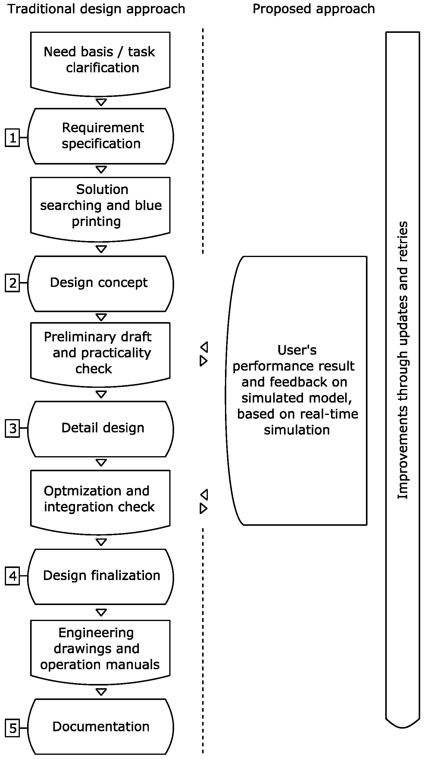
Figure 1 shows the underlying structure of traditional design methods, as presented by Tomiyama [
8,
9] (on the right) and its suggested improvement (on the left). In the figure, VDI 2221 (Verein Deutscher Ingenieure or Association of German Engineers) Systematic Approach to the Design of Technical Systems and Products [
8] represents conventional design processes for mechanical parts. The design steps start with definition of the requirements and initial searching for a solution. The requirements are the needs of the customer, which, following clarification, often specify how the product is planned to be operated and what expectations need to be fulfilled, including prioritization of performance aspects of the product. In the second step, the conceptual design phase, solutions are sought to provide a basis for addressing the problem, which requires further analysis. More complete details, including layout and placement of the components, are generated in the third step. Extras and additional components (e.g., for decoration purposes) are also added in this phase. This step can be divided into modules or elements which are based on solution principles (step 2). Here, the modules are parts that are difficult to alter but are taken as a whole to serve a purpose (e.g., engines in vehicles are not product-specific). Concurrently, elements are specifically designed to fit product specifications. Step 4 considers the compatibility of the system to different components and manufacturing methods and includes cost analysis. The knowledge gained enables the designer to produce the final design. Then, in the last step, step 5, documentation is prepared before manufacturing [
8].
Alongside such methods, product-service systems (PSS) have been introduced, with the aim of serving users (customers) by associating physical commodities with services designed to help users make optimal use of an already purchased product [
9]. Improving services provision and satisfying user needs to obtain higher loyalty can be addressed using the PSS concept. In the model presented in this paper, these aims are examined through use-oriented and results-oriented consideration of the product before design finalization. Additionally, better communication and project knowledge transfer between the consumption and production parts of the PSS are expected [
12,
13].
The frame of reference of the methodology in this process is constructed around decision making and systematic data acquisition in steps 2 and 3 of the design phase of product development, and the methodology also incorporates concepts of PSS. The first step in this process follows the traditional guideline of the design process with a statement of need from the user side, e.g., from the user of the machine. This stage normally includes a combination of several concepts or modules that together form an interdisciplinary task (e.g., the design of hydraulics and the sizing of the bucket). The specification is then produced based on the user needs and the next step, i.e., concept design of the product, commences [
13]. Preliminary sketches are made, which are then assessed based on cost or performance priorities, providing a path towards detailed design. This stage is normally constructed with careful consideration of boundaries and limitations, for example, total acceptable weight or overall dimensions, unless there is a very specific requirement governing the design concept (e.g., a requirement for operability in extreme arctic conditions). Mechanical strength calculation and other detailed design processes then complete draft revisions. Once final optimization and reviews have been performed, engineering drawings can be produced and further steps towards manufacturing started [
10,
11].
In complex systems, the machine is not a final product but plays the role of a tool. Consequently, it has to be able to fulfil a variety of tasks and operate in different environmental conditions; furthermore, it is influenced by the techniques and the skills of the user. Forklifts, excavators, and wheel-loaders are examples of industrial machines for which the designer might not have all necessary input data about machine operations [
12,
14] at the design clarification stage. This uncertainty regarding operating conditions and constraints becomes even more marked when the tasks that users should carry out are case-dependent on other variables, such as environmental conditions. The design process then becomes highly fluid and numerous cases and scenarios need to be investigated for successful selection of the final design. The interplay between the product and the desired outcome of product utilization is in line with the PSS orientation, i.e., consumers are not demanding the product itself but are in pursuit of the utility deriving from utilization of the product in their application area [
2].
Several studies have been conducted around the development of PSS and design knowledge-reuse as a knowledge management framework [
15,
16]. These works aim to develop an effective and appropriate platform for knowledge flow that is suitable for different disciplines and stages of the product life cycle. Even though knowledge-reuse was modeled and applied in the above papers, information and communication of information resources (i.e., the data that are collected from the user, including associated processed information) are considered to remain within the domain of the manufacturing company side. The user is involved in the initial need and task clarification, but user involvement is limited or non-existent in the following stages.
This paper demonstrates integration of simulator use into the concept design stage and detailed design stage of product development. The simulator functions on the basis of dynamic computation in a real-time multibody approach, where bodies, joints, and forces interact with each other. The objective of the study is to introduce a design methodology in which customization is available for defined modular parameters of machine components. In parallel, this study aims to present the potential of a multibody dynamics approach to solve real-world problems. The example case discussed consists of one hydraulic part and one mechanical part. The user, as the client, has the freedom to customize the machine model without needing in-depth knowledge or special expertise in engineering and simulation. Consequently, user contribution to product design enhancement is possible from early stages of prototyping—as shown in step 2 and step 3 in
Figure 1—and improvements in decision making are achievable in terms of features of the multibody system dynamic real-time simulation. To shed light on the introduced design concept, an excavator is considered as an example. Excavators are among the most commonly used mobile machinery equipment in civil engineering and their design and use include complex interconnected bodies and sophisticated design [
17]. The digging mechanisms and complex components of excavators mean that they are a suitable example for examination of the potential of the proposed approach for product development of mobile machinery.
2. Materials and Methods
In this section, a schematic of the idea is first explained and the multibody real-time simulation part, which is the backbone of the method, is then described as it relates to the PSS concept. Next, the background for the hydraulic design, the modularity using XML (Extensible Markup Language) format, and the customer interface are presented.
One iteration of the design process is explained for the case example. In each iteration, the model was updated based on the outcome of the previous step until the desired results were achieved. It was assumed that more than one part of the machine was involved in the design case and that the parts interacted, and their performance was interdependent. In the illustration of the applicability of the method, the goal was to make decisions about proper bucket size and the arm-attached hydraulic cylinder, which represent the goals in the mechanical and hydraulic design, respectively.
The modeling part of a design process traditionally starts with an initial estimation. This initial estimation is based on prior knowledge and previous experience of the designer. For example; when the breadth of the bucket for a 20-ton excavator has a range between 300 and 1200 mm, a value of 750 mm is taken as a starting point. The same procedure is possible for hydraulic cylinders with bore diameter ranges.
Figure 2 shows the proposed concept design and detailed design steps (stage 2 and 3 in
Figure 1) with respect to the traditional design approach.
Three values, i.e., minimum, mid, and maximum, were used for mechanical dimensioning. Based on the parts, a model could be built as a combination of every single choice (here, nine models, as a multiplication of three by three). The choices were then given to the target group, i.e., the users, to utilize in real-time simulation. The designers recorded the simulation data in their area of interest (see the results section). On the basis of the first results, refinements for the second round of choices (i.e., minimum, mid, and maximum values) could be proposed. Once the desired result met the designer priorities (based on the target requirements of the designer), dimensioning was completed, and the design process proceeded to the next steps for detailed design, e.g., material selection, tolerances.
2.1. Multibody Systems
Multibody system dynamics is a straightforward computational approach that can be used to analyze dynamic responses of bodies that are in interaction with each other, i.e., connected by joints. The bodies can be defined as either rigid or flexible, and the multibody system dynamics stay valid for large rotational and translational movements. When this interaction extends from machine components to a human (as a human-in-the-loop) the real-time simulation concept moves to the foreground. Running a real-time simulation in practice has challenged simulators, because of the complexity of finding reliable simulation models and the considerable computational demands. Study of multibody systems is attempting to address these limitations [
18].
Relative coordinates in open chain systems where the main dynamic formulation is founded on a topological system form the basis of the semi-recursive method. When each body (index
j) coordinate is pointed relative to the previous body (index
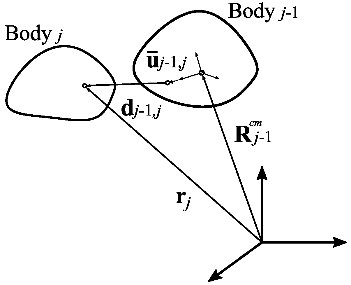
j − 1) in the model tree, relative accelerations, velocities, and positions, as well as Lagrange multipliers, are employed to carry out dynamic analysis. In this approach, the position vector of body
j in the global coordinate system can be written as:
where
is a position vector for the parent of body
in its center of mass,
is a rotation matrix, and
is the body coordinate system in the parent body reference. In Equation (1),
is the relative displacement vector for body
j with respect to body
, as shown in
Figure 3. For body
j, orientation matrix
can be expressed:
where
is the relative rotation matrix of body
j referenced to the previous body in the chain. The velocity associated with body
j can be obtained by differentiating Equation (1) with respect to time, as follows:
where
is the velocity vector of the parent body
j − 1,
is the skew symmetric matrix of the relative angular velocity (between body
j and its previous body in the chain),
is the result of multiplication of rotation matrix
and
, and eventually
is the velocity of the body
j to its precedent body in the chain. Then, the vector of acceleration in the global coordinate system
of Equation (3) can be derived as:
where
is acceleration of the body
, in its center of mass,
is a time derivative of the skew symmetric matrix of the relative angular velocity, and
is relative angular acceleration.
Velocity and the acceleration vector in the center of mass are written based on relative rotation matrices and relative skew symmetric matrices of angular velocity [
19,
20]. Solving such a system of equations consisting of generalized coordinate systems demands considerable computation resources, while practical requirements for running a real-time simulation must not be neglected. To overcome this barrier, velocity transformation can be employed to express the equation of motion in terms of the generalized velocity and acceleration. Generalized velocity and acceleration, correspondingly, can be written as:
where
and
are generalized velocity and acceleration, respectively,
is a velocity transformation matrix,
and
are relative joint velocity, and acceleration
is the first derivative of the velocity transformation with respect to time. In three-dimensional space, the velocity transformation matrix for each body—without a parent body—is a matrix of six rows by
c-columns, where
c is the number of constraints of degrees of freedom. As an example, a spherical joint in body
j had a six by three transformation matrix, which was multiplied by all its parent bodies (Bodies
,
…) in the model tree to form a full velocity transformation [
19]. The equation of motion, using Equation (5), can be written as:
where
is the mass matrix,
is the generalized accelerations, and
and
are vectors of generalized forces and quadratic velocity, respectively. In the semi-recursive method, the equation of motion in the form of Equation (5) is multiplied by the transpose of the velocity transformation matrix to assure invertibility of the mass matrix. Computationally parallelizable [
20]
and
terms can be introduced as:
and the solvable form of the equation can be combined with penalty terms to account for closed loops. So, the final form of the equation of motion is written as:
where
and
are Jacobians of the constraints with respect to the relative joint displacement vector and its first derivative, and matrix
α contains values of the penalty term, as well as
Ω and
ξ, which are matrices for corresponding natural frequency and damping ratios of the penalty systems defined for each constraint condition [
18,
21,
22].
2.2. Hydraulics
Hydraulics in this study were modeled using a semi-empirical method that assumed that the pressure variation within a volume was negligible. In this approach, valves and long hose lines were modeled as throttles. A pressure within a hydraulic volume index
i (
) can be estimated using a first order differential equation as:
where
is the derivative of pressure
with respect to time,
and
are volume size and its derivative with respect to time,
is effective bulk modulus, and
is flowrate, with
and
the entering and outgoing flow rates of the control volume, respectively. Hydraulic valves introducing pressure losses and flow rate through a valve can be estimated as:
where
is a semi-empiric flow constant,
is the pressure difference between two sides of the flow, and
, as the spool position symbol, is calculated by integration of the following equation with respect to time
:
where
is the reference spool position, and
τ is a time constant [
23].
2.3. Collision and Soil Model
The computational cost of collision detection algorithms is a key concern in real-time simulation. This challenge increases exponentially with respect to the number of colliding elements. Contact force is only calculated when a collision between bodies is identified in a prior time step, so contact forces are dismissed when there is a gap between two bodies. This approach is possible through multi-stage collision detection strategies, such as rough spherical boundaries and detailed spherical boundaries, as explained in [
24]. Spherical and cylindrical geometries were employed to approximate the outermost boundaries of a body and elevate the computational efficiency of the real-time simulation. At the same time, the contact forces were sensitive to the time step of the simulation, since high velocity actuation can introduce inaccuracy in the behavior of colliding bodies, leading to dynamic instabilities in the real-time simulation.
Contacts and collisions are one of the most complex parts of real-time simulated models. Bounding geometries methods like oriented bounding box (OBB) can be applied to calculate the interaction forces after intersection between objects is detected. Triangular definition of the geometry to formulate the model average and its covariance matrix can be considered as:
where
is model average,
b is number of triangles, vertices of triangle
i are shown by
,
and
, and
is the correlated covariance matrix [
21,
25].
In a real-time environment, a realistic soil model plays an important role in the dynamics of mobile machinery. A number of methods for soil modeling are available in the literature using algorithms such as RAPID, V-Collide and I-Collide [
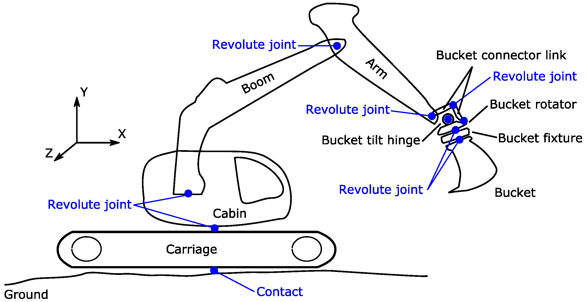
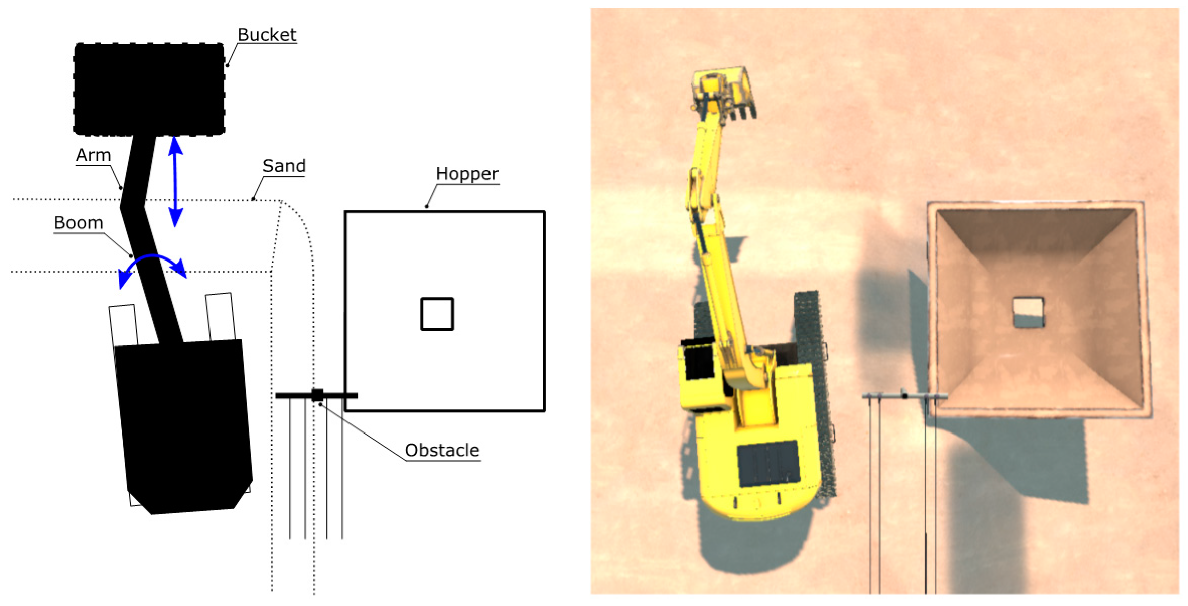
25], which are based on the principles of OBB. In such models, the best-fitting polygon breaks into triangulated geometries. Overlapping geometries are then treated using an impulse-based or constraints-based approach. When contact is not detected, particles follow their trajectory under the influence of gravity until they either land on each other, bounce, or slide through each other. The stacked particles from a planar soil surface simulate shrinkage and compression by consideration of a soil recovery factor and the time history of the normal terrain stress. In the case example under consideration, the excavator remained stationary and the excavation maneuver was performed by movements of the cabin (see
Figure 4), boom, and other connected bodies. Since crawlers (which are attached to the carriage) were not active, the tread pattern of the excavator grouser shoes was not modeled and the crawlers were presented as a flat surface rather than a corrugated pattern [
26], which helped channel computational power and avoid unnecessary complications.
2.4. Excavator Model
In this paper, the pair (as the part 1 and the part 2 which previously were mentioned in
Figure 2) in the design process were the bucket size and the arm-attached double-acting hydraulic cylinder, considering that the bucket should be functional such that the user has enough force to excavate and fill the bucket. The excavator in this case example was modeled using 10 independent bodies. The bucket was used as a tool to transfer sand with a density of 2000 kg/m
3 to a destination (a hopper). The carriage of the excavator was floated on the ground, which made it the only non-holonomic constraint in the model. The topological map of the excavator is presented in
Figure 4. The chain of bodies of the excavator was contiguous and the structure of the excavator was robust in exposure to normal excavation maneuvers, so the flexibility of parts such as the arm and boom (rigid bodies) was minimal. For simplification of the topology, tracked parts of the excavator, which produced traction in interaction with the ground, are not illustrated in the figure.
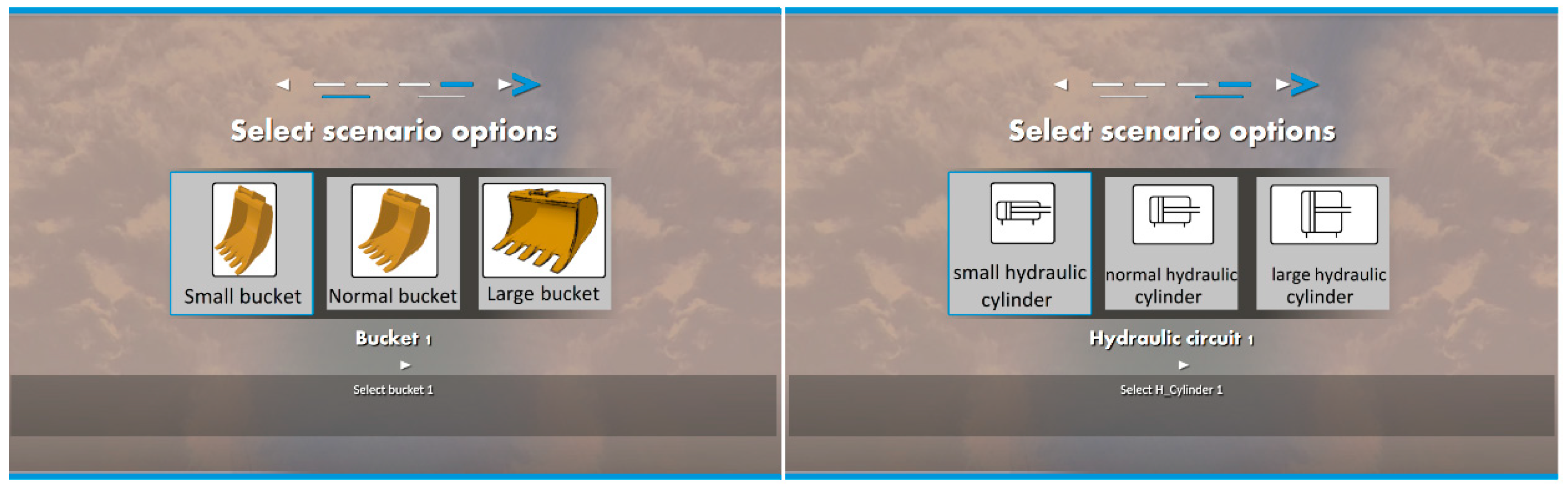
The mathematical representation of the system, including definition of the bodies, constraints, and forces, was implemented in an XML database, where each component of the machine sat in one subfolder, accompanied by its attributes. Storage of the data in this way benefited the modeling within the context of knowledge management as the two correlated key components of the excavator served the proposed method. These components remained independent and discrete, while the whole model stayed integrated as a group of segmented components in XML format. First and foremost, bucket size—which is also representative of bucket capacity—was taken as an alternative that was determined by the operator of the excavator. Three different bucket sizes were used in this experiment so the user could select their own configuration. The other optional key component was the hydraulic actuator that generated the force between the arm body (stick) and bucket connector link.
Figure 5 presents the interface for user selection. The software replaced the modular properties of the component based on the selection made by the operator.
The risk of collision for larger bucket sizes was higher as handling a larger bucket is geometrically challenging. Collisions were possible between the bucket and hopper edge, and also between the boom/arm and an obstacle, which in the case under study was an electric pole. The obstacle was intentionally placed near the operation area, so if the user slewed further than the required maneuver, the boom, arm, or bucket may approach the pole. As an example,
Figure 6 shows a top view of the initial location of the excavator and a schematic of the main objects located nearby.
There is a trade-off for bucket size in an excavator; a higher bucket volume helps operators achieve higher productivity of soil excavation, but large, bulky buckets can lead to higher risk of collision, controllability problems, difficulties in soil excavation, and more demanding hydraulic circuits to actuate.
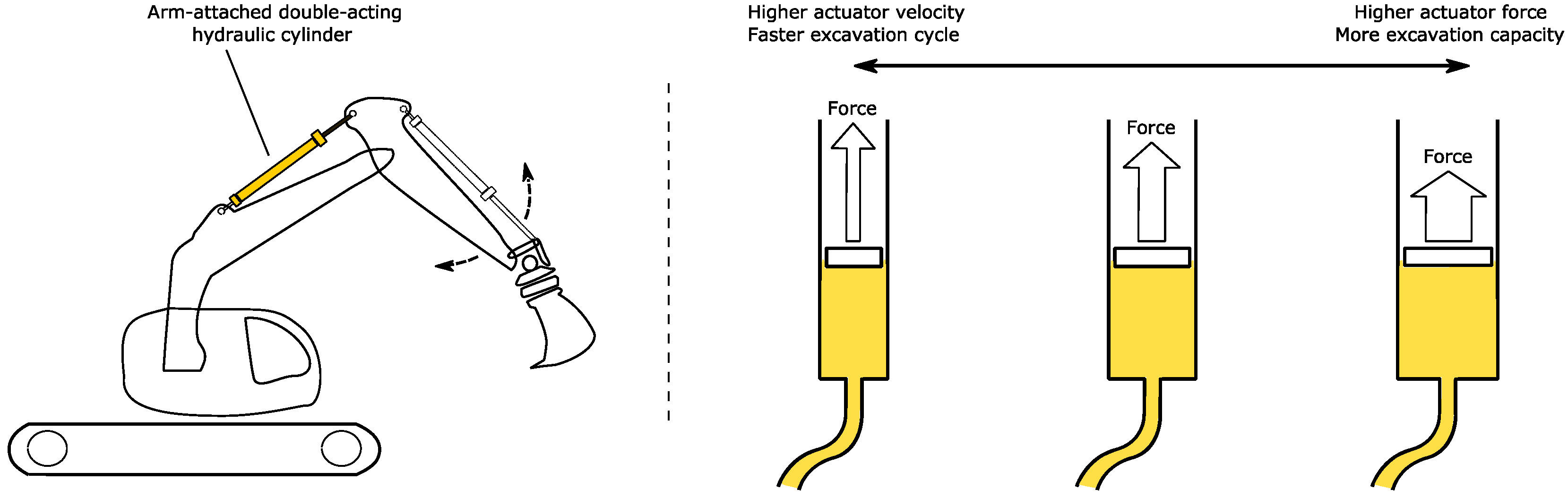
A similar trade-off was seen for actuation of the bucket with the hydraulics of the arm, as illustrated schematically in
Figure 7. The bucket excavation force, which is an important parameter for excavation productivity, must be considered together with the cycle time. This helps to determine the most suitable cylinder geometry and to address user needs—involving soil properties and the site field situation—accordingly.
Selections by the user led to the implementation of changes in the model tree. Changes had effects in different areas, for example, bucket selection would merge a subfolder in the XML-based model. Definition of the mass and inertia, as well as the graphics and geometrical definition of the bucket, were provided through the correlated subfolder. Three-dimensional geometries were introduced in 3DS (3D Studio) format [
27]. An example of properties for hydraulic components is shown in
Table 1, which presents data for a sample hydraulic cylinder.
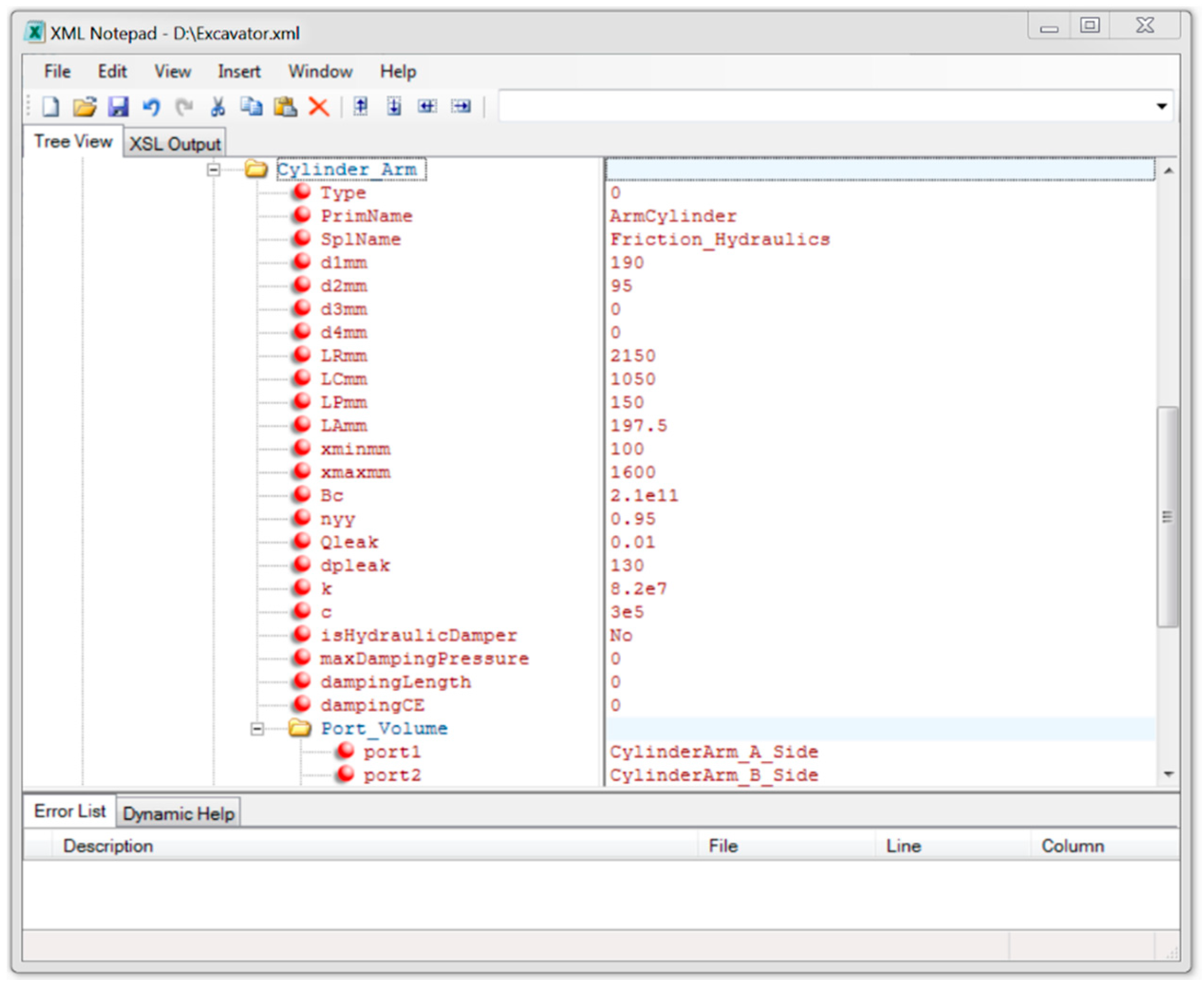
User selections for the cylinder led to the implementation of an XML subfolder, as displayed in
Figure 8, including graphical representation, geometrical specifications, stiffness/damping properties, relevant friction coefficients, and connecting hydraulic elements, as an interpretation of
Table 1. It should be mentioned that the bulk modulus of the hydraulic oil in the system was here assumed to be constant with respect to pressure, and the bulk modulus presented in the table belongs to the cylinder alone and does not include other connected volumes.
The XML definitions allowed the user to make the model communicate with a variety of other components. Here, the model tree, which was the input of the simulation software, was also based on XML format, and components could therefore be integrated to make a complete model that included all bodies, constraints, forces, input definitions, environment data, and colliding geometries in the final stage [
22]. A dynamic solver then processed the XML files to make a real-time physics-based visualization. The data required for post-processing were obtainable visually and numerically, and produced based on user inputs. A sample of numerical results is presented in the next section.
3. Results
During the product development process, the designer considers different aspects of the design with the aim of moving towards reduced energy and material consumption. It is thus beneficial to study the effect of changes to different components on the dynamic behavior of the real-time simulation; an example of such studies is presented in [
3]. In this case study, samples were taken from the effect of changing the arm-attached cylinders on excavation force or the effect of change in bucket size on the fuel consumption, applicability, and speed of the process. These samples were meant to demonstrate how the capability of coupled parts can be checked to answer user needs based on user criteria and preferences.
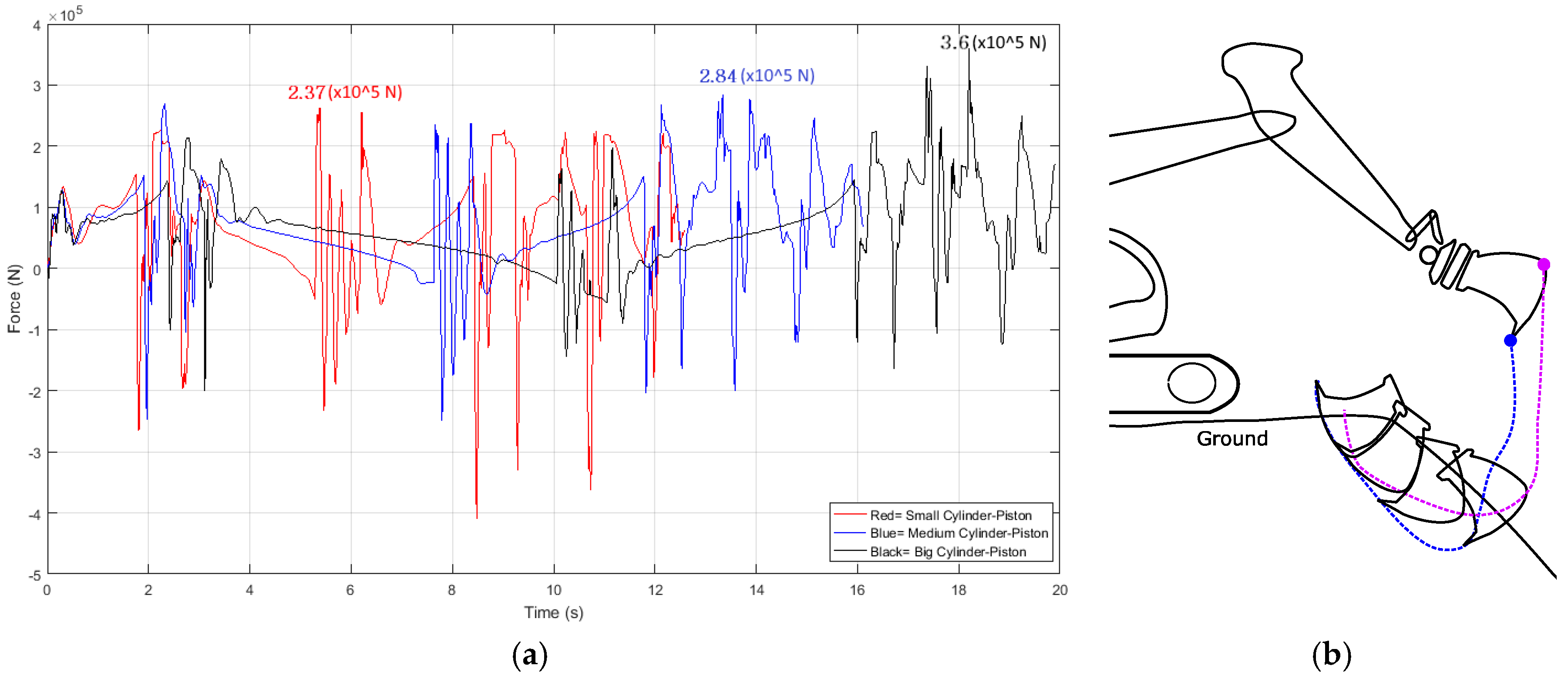
Samples of such collected data are presented in
Figure 9a and
Figure 10. Considering the actuator force, the figures show change in the performance of three different arm-attached cylinders in response to an input signal. The maximum values for the small, the medium, and the large actuator are marked in the figure to ease comparison of generated forces. The forces in the figures are for a sample trenching movement filling the bucket with sand. The fluctuations represent the friction and separation forces needed to excavate the ground during the operation shown in
Figure 9b.
One difficulty in design work for complicated machine-like excavators is ambiguity about the consequences of changes that do not exhibit a direct effect or have a linear relationship with respect to changing parameters. This challenge can be tackled in two ways. Firstly, the designer is free to choose and try a different setup through initial estimation, which results in a rapid trial-and-error process to outline a general plan and can help to define the boundaries. Secondly, optimization in certain ranges can be performed through a loop by adding a small amount of change (as a step) in one variable, followed by analysis of the result, especially when a mechanical part (e.g., a bearing) is chosen from a catalogue.
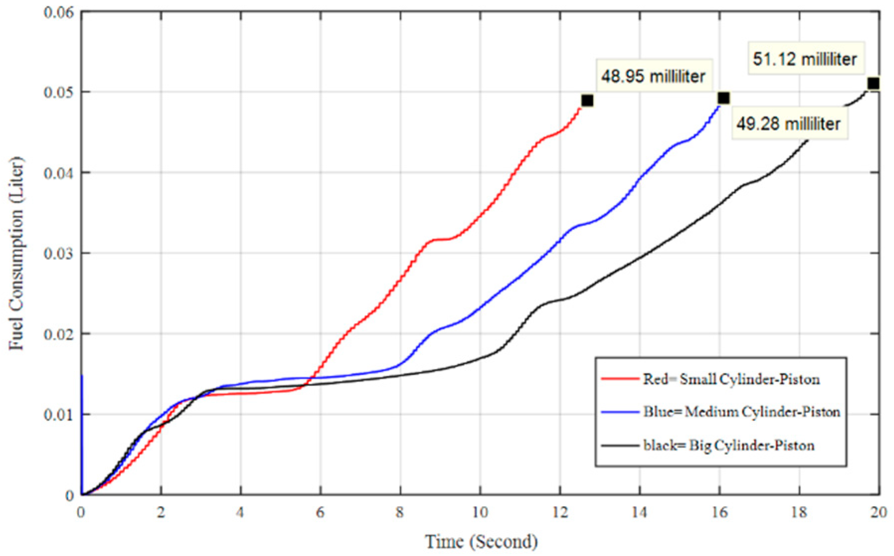
Fuel consumption is an issue that is difficult to investigate with simple mathematical formula. The difficulty is a consequence of the multi-lateral dependency of engine fuel consumption on other variables, such as actuation of components in the hydraulic circuit.
Figure 10 shows the effects on fuel consumption for three types of arm-attached cylinder when the excavator was in a parked position (i.e., when the crawlers were not operated for transferring the bulk material) in response to a similar control input signal for the arm-attached cylinder. As can be expected, the highest value of fuel consumption was found for the largest rod area. It should be noted that higher productivity depends on the excavation application and comes at the expense of higher fuel consumption. Therefore, in the final selection of the size, this interplay needs to be taken into account simultaneously.
4. Analysis and Discussion
Small bucket size and small cylinder size were taken as the first guess of the design process. The results section presented one step for the design iteration and expected outcome from each iteration. The process was repeatable, and users were therefore trained through their choices of combinations of bucket selection and hydraulic-circuit selection. This approach can be employed for other similar mobile machinery using a bucket for loading bulk material (e.g., wheel loaders) or with a similar group of mechanical or hydraulic parts.
One element of the design iteration, based on
Figure 1, was an integration check, which also included evaluation of the practicality of use of different bucket sizes and possible risks (as introduced by the number of collisions) associated with such design alternatives. Productivity was measured by the amount of sand delivered to the designated destination in a limited time span. Change in bucket size and attached hydraulics could be adopted based on the preferred strategy by considering budget, safety, or machine performance.
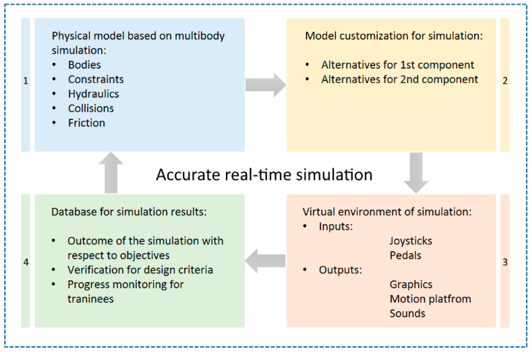
Figure 11 depicts the optimization and integration check initially introduced in the first chapter on the basis of modeling, customization, interaction, and results. The key idea in this method was communication of information about the effects of component design decisions via an accurate real-time simulation that showed the combined impact of parameter changes (for the example in
Figure 11, the first component and second component). Evaluating such multi-dimensional outcomes is extremely challenging and often impossible using traditional design approaches alone.
This work demonstrated a method for decision making about the size of the bucket and/or sizing of the arm-attached hydraulic actuator (also known as dipper arm). The described approach can benefit designers when it is used as a tool for product development and design optimization. The excavator model was used as a virtual test bench for the project. Easy customization was available and allowed users (e.g., end-users as machine operators) to choose and try different components of the excavator. In previous methods, as presented by Zheng [
28] or Xu [
29], even though the model parameters were partly adjustable, the options were not meant to make an interactive model with operator contribution, and model components were thus fixed from the operator’s point of view and the focus was on the compatibility of components in modules. Different aspects of inter-disciplinary engineering design and the data circulation of the design work were addressed in [
30] and [
31], but user interaction in these works considered user input mainly in the final stages of the design and product process.
In the work in this paper, validation of the proposed method was performed using a desktop computer with Logitech Force 3D pro joysticks. A PC with an Intel Core i7-6700 processor equipped with 64 GB of RAM and an NVIDIA Quadro M2000 GPU was able to run the simulation with a 1 millisecond time step, which permitted user interaction as real-time simulation. An example test screen is given in
Figure 12. Based on the on-screen images, the excavator operators could instantly observe the effects of their selections on aspects such as productivity (here this was excavation cycle times) and fuel consumption.
Test results are also available to be recorded and collected for further analysis, where simulation repeatability provides a basis for decision making about the real product and the simulated product can be seen as a digital twin. Combining parameterizations of different components, which is discernable as rapid prototyping in designers’ hands, reduces the time required for modeling, validation, and testing, as modular component modeling is used for the machine to be designed. Additionally, the proposed approach is suitable for use in crowdsourcing [
32].
5. Conclusions
This paper described an approach for customized modeling for machine design using state-of-the-art multi-body simulation techniques that made it possible to run a complicated multi-aspect real-time simulation on a normal budget PC. Use of this methodology provides the designer with the data required to meet customer needs already in the early and middle steps of the design process. To illustrate application of the methodology, the paper presented an example of the design of an excavator bucket for bulk material excavation. The proposed approach paves the way for faster product development and improved user satisfaction. User priorities can be met in a more systematic manner when the product development process is handled on the basis of user-generated data that do not require the user to consider complex engineering details.
The proposed method creates a basis for introducing user feedback through an XML-based multibody model of an excavator, and clients who use the machine as a tool can make a meaningful contribution to the design when searching for optimum parameters for the specific application and environment conditions. Environment conditions here were interpreted as soil density, cohesive modulus, friction modulus, and other terramechanical variables that may affect the excavation process, such as risk of collision with obstacles.
When interrelated design factors are involved in product design of a complex system, the presented approach can benefit the designer by enabling better visualization of the impact of changes—through customized modular parameters—on other components and related processes of the system.


