Article

Dynamic Performance of a Squeeze Film Damper with a Cylindrical Roller Bearing under a Large Static Radial Loading Range

1
Department of Mechanical Engineering, Vrije Universiteit Brussel, Pleinlaan 2, 1050 Brussels, Belgium
2
Department of Mechanical Engineering, KU Leuven, Celestijnenlaan 300B, 3001 Leuven, Belgium
*
Author to whom correspondence should be addressed.
Machines 2019, 7(1), 14; https://doi.org/10.3390/machines7010014
Submission received: 20 December 2018 / Revised: 29 January 2019 / Accepted: 29 January 2019 / Published: 3 February 2019

Abstract

:
Turbomachine rotors, supported by little damped rolling element bearings, are generally sensitive to unbalance excitation. Accordingly, most machines incorporate squeeze film damper technology to dissipate mechanical energy caused by rotor vibrations and to ensure stable operation. When developing a novel geared turbomachine able to cover a large power range, a uniform mechanical drivetrain needs to perform well over the large operational loading range. Especially, the rotor support, containing a squeeze film damper and cylindrical roller bearing in series, is of vital importance in this respect. Thus, the direct objective of this research project was to map the performance of the envisioned rotor support by estimating the damping ratio based on the simulated and measured vibration response during run-up. An academic test rig was developed to provide an in-depth analysis on the key components in a more controlled setting. Both the numerical simulation and measurement results exposed severe vibration problems for an insufficiently radial loaded bearing due to a pronounced anisotropic bearing stiffness. As a result, a split first whirl mode arose with its backward component heavily triggered by the synchronous unbalance excitation. Hence, the proposed SFD does not function properly in the lower radial loading range. Increasing the static load on the bearing or providing a modified rotor support for the lower power variants will help mitigating the vibration issues.

1. Introduction

Nowadays, modern turbomachinery are equipped with custom-designed, and thus rather expensive, fluid film bearings. Despite their high speed, load, and inherent damping capabilities, fluid film bearings are prone to rotor dynamic instability issues and consume a considerable amount of available torque [1,2]. Because rolling element bearings generate less frictional torque, are less expensive and eliminate the bearing instability issues, their use can aid in improving a machine’s energy-efficiency, production cost, and reliability [3,4]. Besides, to meet the turbomachine’s aerodynamic-determined properties, the mechanical drive train needs to operate at very high rotational speeds and, hence, above several critical speeds. To let a rotor, supported by little damped rolling element bearings, pass safely through these critical speeds, appropriate external damping needs to be provided. Squeeze film damper (SFD) technology is an effective means to dissipate mechanical energy caused by rotor vibrations and to provide structural isolation of the rotor from its housing [5].
Despite the fact that SFD technology has reached a level of practical applicability in the custom-designed turbomachinery [6,7], aviation [8], and aerospace industries, several challenges need to be overcome prior to the introduction in the design of more standardized turbomachinery for large volume production. When aiming to increase production volumes and, therefore, reduce the expenses to improve profitability, a large power range needs to be covered using the same core components. Moreover, the rotor support, consisting of a cylindrical roller bearing (CRB) positioned in a SFD, is subjected to a large static operational loading range. This paper presents a profound investigation of the rotor support under a large static loading range by making use of a dedicated test rig. Besides, some advanced calculation tools, which are essential to comprehend the performance of the rotor support system, are shown.
The paper is organized in the following manner. Section 2 starts with a general description of oil-damped rotor supports, after which the remainder is devoted to a brief review of the technology. Section 3 tackles the rotor dynamic model and the performed numerical analysis. Section 4 starts with an overview of the developed rotor dynamic test rig, along with the measurement procedure and the used data processing. Next, the experimental results are presented and discussed. The last Section 5 summarizes and concludes this work.

2. Oil-Damped Rotor Support—Squeeze Film Dampers

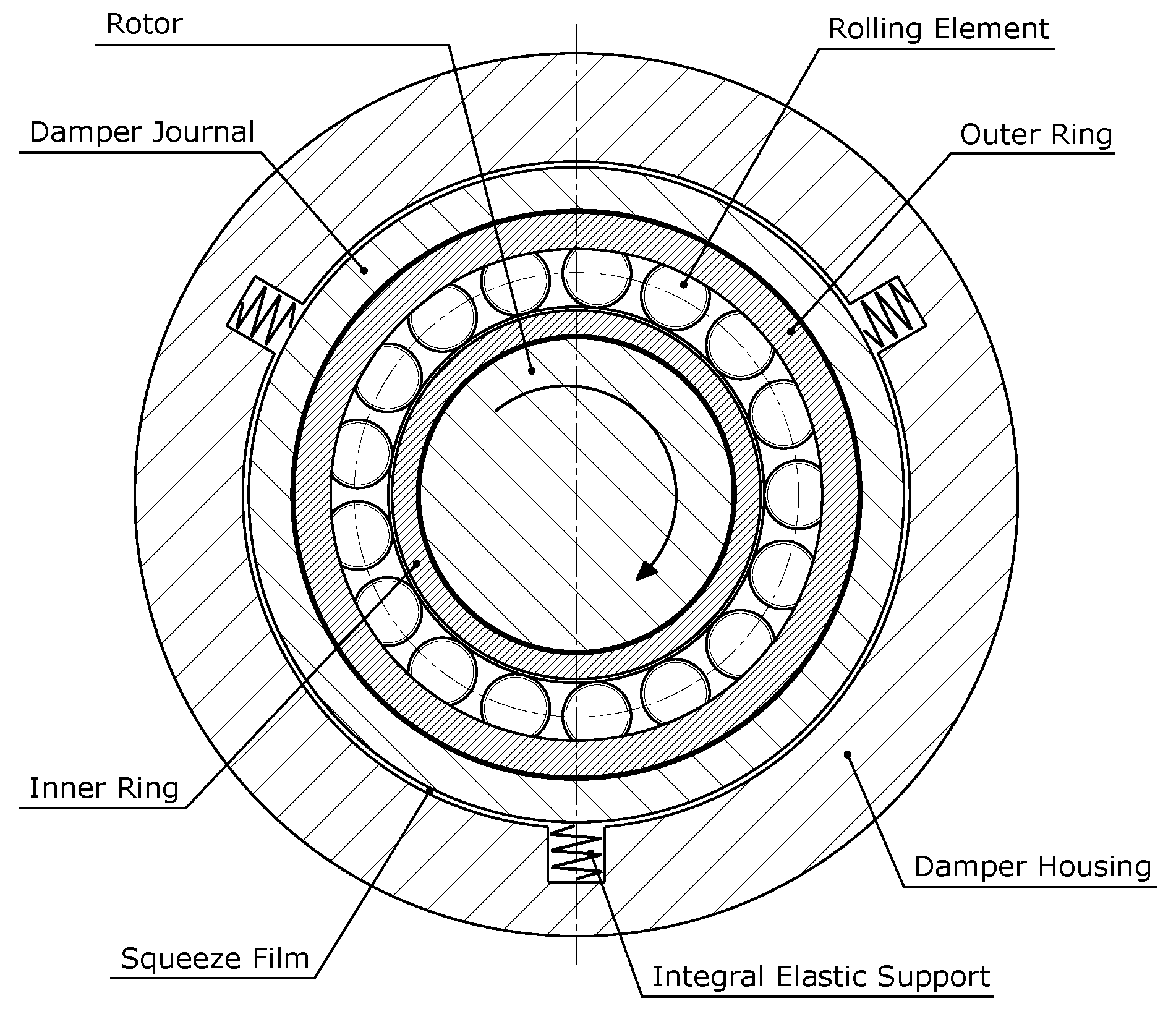
2.1. Description of a Squeeze Film Damper

Generally, a SFD comprises an inner non-rotating journal fixed to the outer ring of the fluid film or rolling element bearing and a stationary outer housing. Allowing a small circumferential gap in between the journal and housing, being fed by a pressurized lubricant supply, creates a so-called oil squeeze film, as can be seen in Figure 1. During operation, an orbital motion of the inner journal relative to the housing is observed, due to dynamic loads acting on the rotor system. As a result, hydrodynamic pressures are generated, which exert opposing fluid film forces on the inner journal to reduce large amplitude rotor displacements and attenuate transmitted forces towards the supporting structure. Vital to this practice is the amount of damping produced. If there is too little damping, the damper is ineffective and likely to permit large amplitude rotor dynamic displacements. On the contrary, if damping reaches too high values, the SFD acts as a rigid constraint transmitting large dynamic forces to the supporting structure.
Not only geometric and lubricant properties determine the overall performance of a SFD, mainly the rotor dynamic operating condition is of vital importance. Moreover, the lubricant supply pressure or temperature, along with its feeding and discharge flow mechanisms, type of end seals, and presence of dynamic cavitation are other contributing factors in this regard. An overview of the most commonly used configurations is presented in [1].
In Figure 1, a SFD with an integral elastic support is presented. This specific design allows accurately determining the stiffness of the rotor support, which evidently needs to be lower than the bearing stiffness. As a result, good predictability and precise placement of the critical speeds and rotor modes is feasible.

2.2. Brief Review of Squeeze Film Damper Technology

Cooper [8] introduced SFDs to reduce excessive synchronous vibrational levels in aircraft gas turbine engines more than half a century ago. Even today, modern refined versions are still equipped with these rather complex machine components [9]. By the early 1970s, fluid film bearing supported customized turbomachinery, which exhibited subsynchronous rotor instabilities during operation, were for the first time fitted with SFDs as a last resort to stabilize the rotor system [6]. The prior approach is still used to reduce vibration levels or enhance the rotor dynamic behavior [7]. In the automotive industry, fluid film bearing-equipped turbochargers are quite common. Recently, by introducing a squeeze film damped rolling element bearing support, a fundamental change in the friction mechanism significantly improved the system’s performance and energy-efficiency in both transient and steady-state operational conditions [3]. Present academic and industrial research interest still goes out to these fairly troublesome rotor support configurations. As a result, the literature on SFDs is vast and most often covers numerous design and geometric aspects, analytical equations to predict the performance and experimental validation using controllable orbital motion test rigs [5,9,10]. Moreover, an interesting overview of research in the field of SFD technology can be found in [11,12].

3. Numerical Simulations of the Rotor-Bearing System
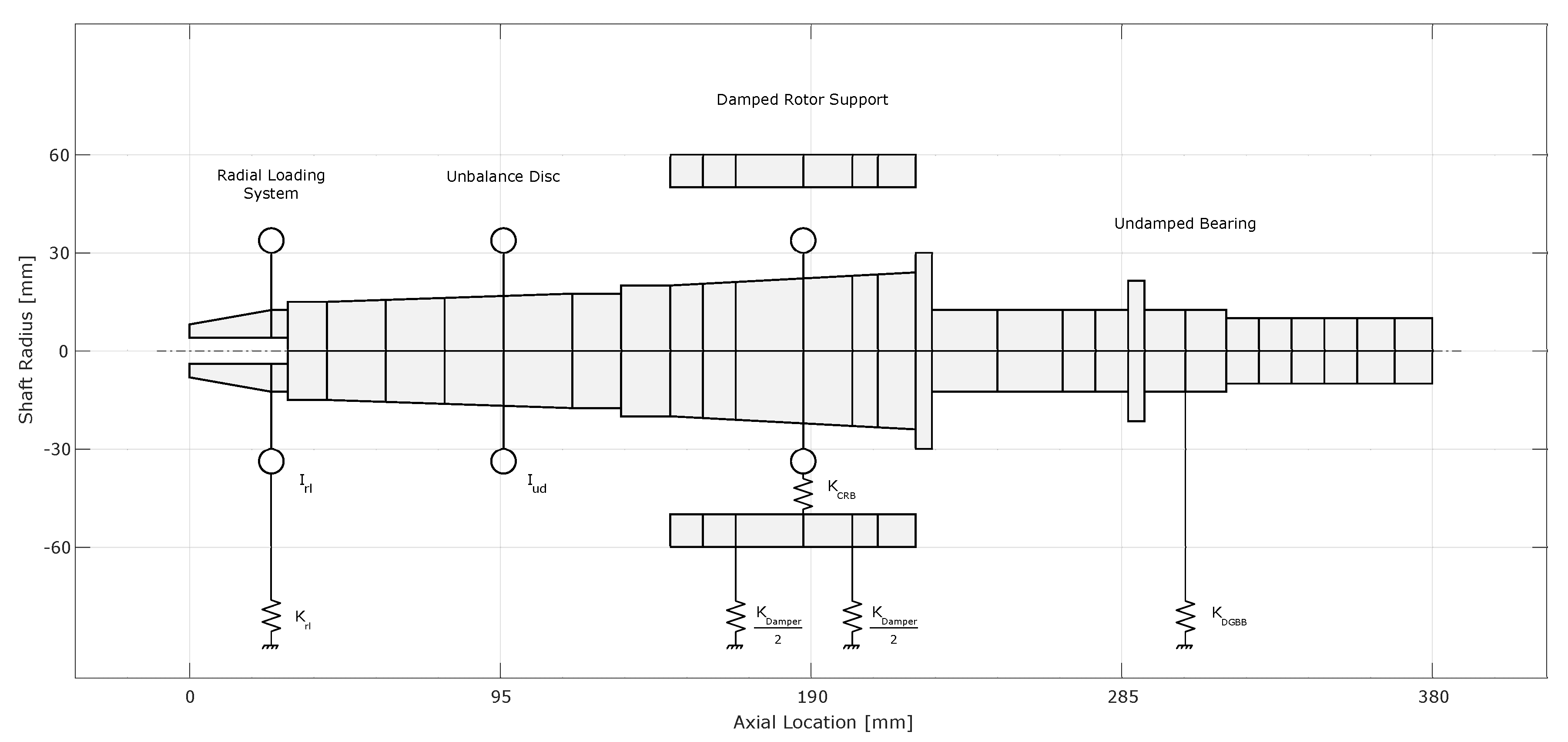
In this section, the necessary numerical model to perform the rotor dynamic analysis is presented, together with the calculation of the resulting damped eigenvalues and forced response. The numerical model needs to clearly reflect the dynamics of the considered industrial application. Leaving a more profound explanation on the entire test rig design to Section 4.1, a brief introduction of the fundamental concept is presented here. The rotor, which contains a large overhung mass represented by the unbalance disc, is supported by two separate bearings. The drive-end bearing is mounted in a rigid housing, whereas the non drive-end bearing is positioned in a SFD. Additionally, the radial load is applied to the end of the rotor via a dedicated loading system.

3.1. Rotor Geometry

A schematic representation of the rotor dynamic model is shown in Figure 2. The rotor geometry is depicted, together with the additional stiffness (K), mass (m) and polar inertia ( I p ) (see Table 1) to model the radial loading system, the unbalance disc and the damped rotor support, respectively.

3.2. Squeeze Film Damper Properties

A simplified model of the damped rotor support, created by a separate housing suspended flexible to the ground, is employed. Based on a finite element analysis of the SFD geometry, a stiffness value of 52 MN/m is determined. The damper stiffness value is selected based on the maximum permissible gear misalignment of the envisioned industrial application. Furthermore, a damping value of 30 kNs/m resembles the calculated oil film damping [13]. Linking the rotor to the flexible housing by the proper bearing stiffness matrix, calculated in Section 3.3, completes the entire model. An overview of the dimensions of the rotor support is presented in Table 2.
Note that, without the separate housing, two dampers (damping of the bearing and damper) are basically connected in series, whereby the lowest value dominates the equivalent damping value. Since the lowest damping value originates from some minor energy dissipating mechanisms inherently present in a bearing (typical value of approximately 1000 Ns/m), such as the local compliance of the rolling elements to the inner and outer raceway, theoretically the SFD will not work. In the end, to cope with this troublesome modeling error, an additional housing is implemented. Moreover, the intermediate housing allows to incorporate the contribution of the non-rotating mass of the damper.

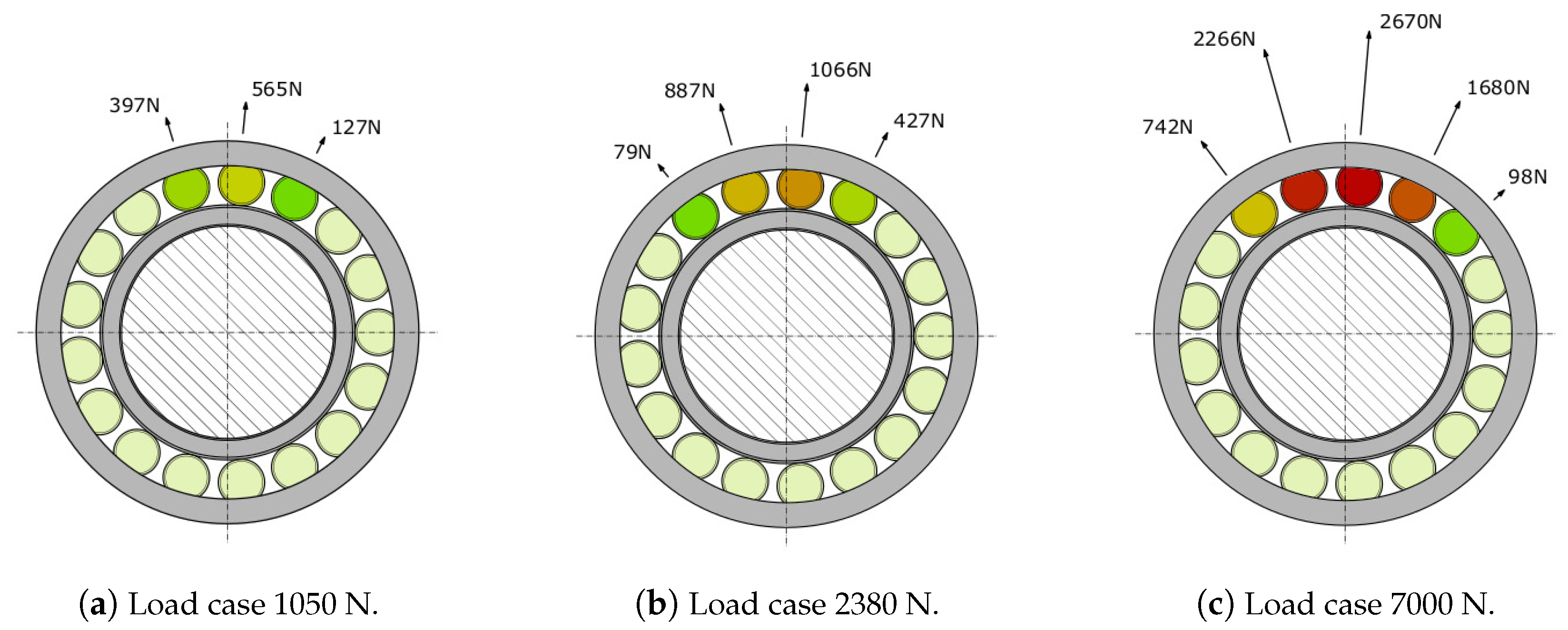
3.3. Bearing Properties: Load Cases and Results

To calculate the bearing stiffness matrices, an academic quasi-static calculation module is used. The module, implemented by the second author, is based on the work of Harris and Kotzalas [14], De Mul [15] and Andréason [16]. To model the non-Hertzian line contact inherently present in CRBs, the so-called slicing technique is exploited [14]. Centrifugal and gyroscopic loading as well as structural deformation of the bearing rings, other than each roller local elastic compliance, are not considered in the analysis.
Three load cases are selected which clearly demarcate the large static operational loading range. Omitting the dynamic loading condition, the load cases only account for the static load present. Therefore, the first load case of 1050 N reproduces the idle or unload condition, while the second case of 2380 N depicts the full-load condition of the lower power variants in the product range. The third load case of 7000 N represents the maximum reachable static load in the upper size of the power range.
The radial bearing reaction loads can be determined using the static equilibrium equations [14]. Note that this static assumption disregards the bearing misalignment and, thus, merely can be used as an initial estimate for the bearing stiffness matrices. Besides, the dynamic amplification on the vibration amplitude emerging when passing a critical speed is also neglected. Figure 3 shows the resulting internal bearing loading for the different load cases. Since the CRB is vertically loaded, the stiffness in the horizontal direction is mainly defined by the number of participating rollers and their corresponding horizontal reaction force components.
Table 3 briefly summarizes the most relevant stiffness values, namely the horizontal and vertical direction with their associated cross-coupling terms. Combined with Figure 3, it is clearly proven that a low unidirectional radial load causes an internal asymmetric load distribution of the cylindrical rollers to arise. So, when the static load is increased, the horizontal and vertical stiffness values will enlarge as well, however, not in a uniformly manner. Depending on the increasing radial load, the Kyy/Kxx-factor drops substantially, designating an evolving symmetric bearing stiffness with radial load. Besides, the mutual influence of the vertical and horizontal direction also lowers significantly. Hence, this simulation proves that an insufficiently loaded CRB shows very asymmetric stiffness conditions, which is one of the key observations for this paper.

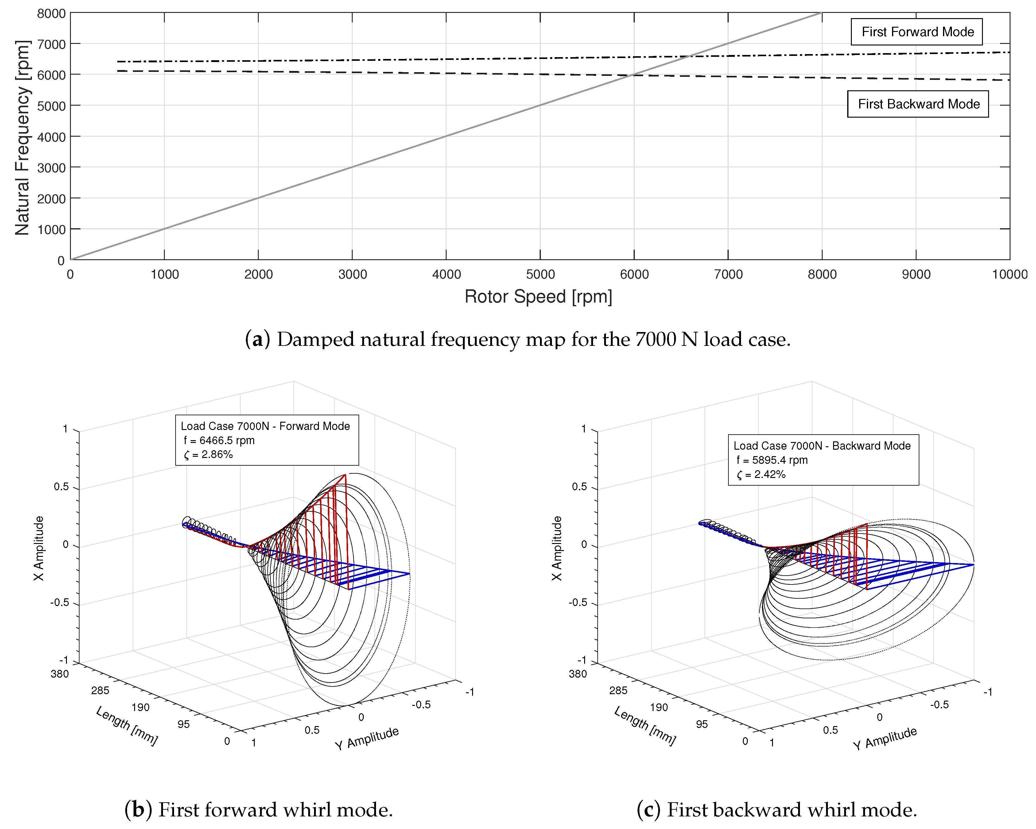
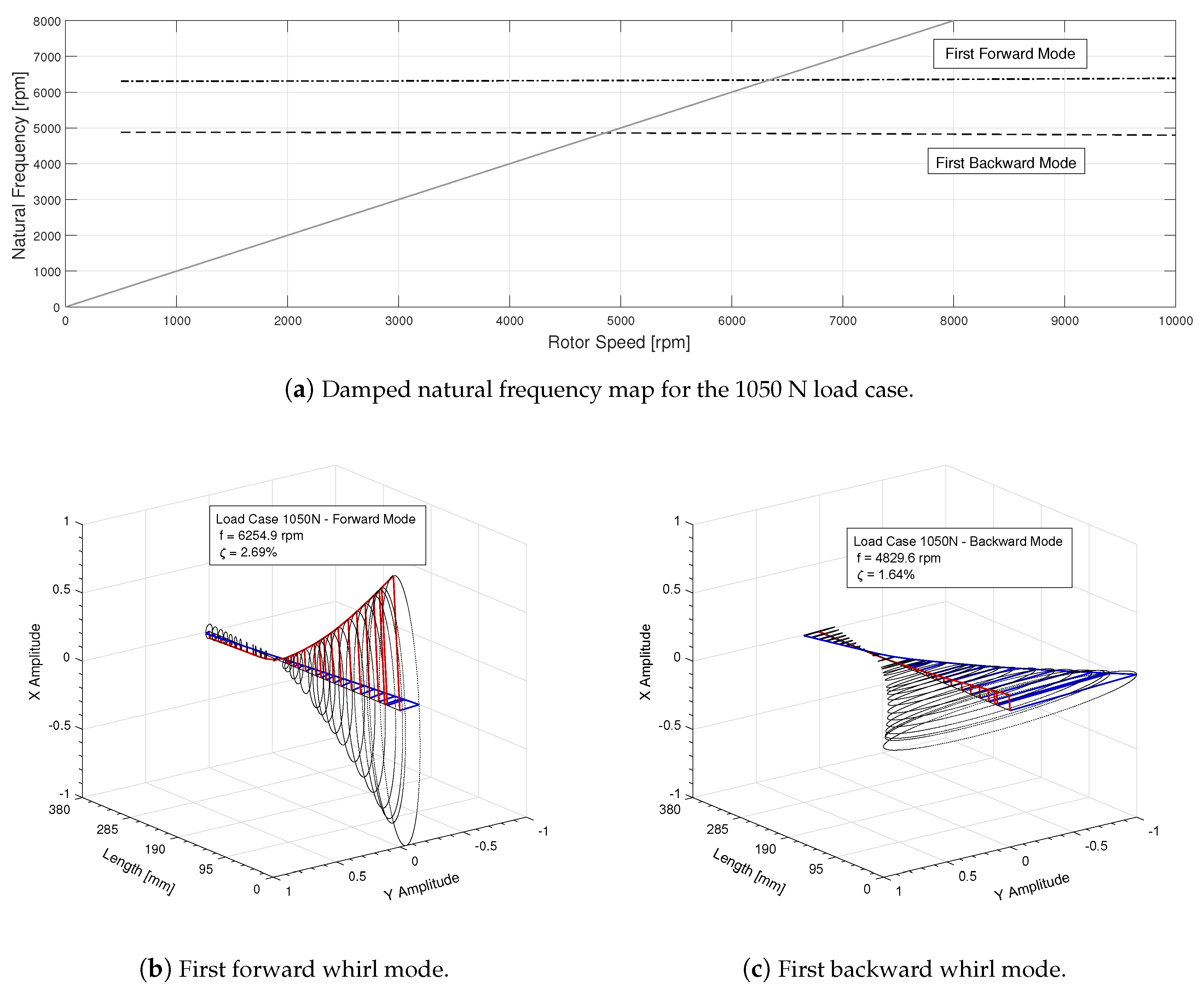
3.4. Damped Eigenvalue Analysis

Since the actual drive train of the industrial turbomachine needs to safely cross the first forward whirl mode during operating, the rotor system needs to accurately reflect these dynamic characteristics and operational conditions. As a result, several design iterations were made and verified by a damped eigenvalue analysis. Figure 4, Figure 5 and Figure 6 represent the damped natural frequency maps with the corresponding mode shapes of the final test rig rotor for the 1050 N, 2380 N and 7000 N static bearing load cases, respectively.
Due to the unidirectional radial static load, an internal asymmetric load distribution of the cylindrical rollers arises, resulting in an anisotropic bearing stiffness. This asymmetric stiffness introduces a significant split between the first backward and forward whirl mode. Besides, notice the highly elliptical shape of the vibration orbits, which is practically horizontal and vertical oriented, for the low radial load cases. The vertically oriented first forward whirl mode is caused by the major stiffness axis properly aligned with the direction of the static load vector. The backward mode propagates along the minor stiffness axis, perpendicular to the major stiffness axis and thus the static load.
By increasing the static load to 2380 N on the CRB, the first damped forward and backward natural frequency will increase slightly. Since the minor (horizontal) stiffness direction increases much more than the major (vertical) stiffness one, the relative distance between both resonances decreases. Additionally, the orbits become less elliptical; however, the distinct horizontal and vertical oriented shape is still recognizable.
Because of the high static load of 7000 N, the internal load distribution of the bearing becomes more and more symmetric. As a result, the split between the first backward and forward whirl mode disappears gradually, whereas the gyroscopic effect has actually a more pronounced influence. In addition, the shape of the vibration orbits evolve into a rather circular pattern.

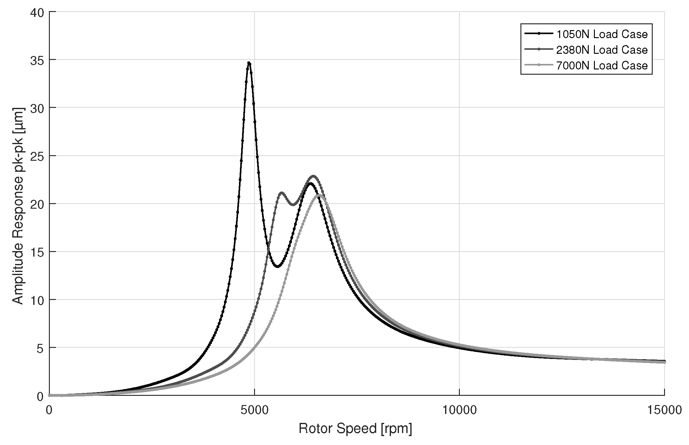
3.5. Forced Response Analysis

After calculating the damped eigenvalues, a forced response analysis is completed for all separate static load cases by adding a forcing function to the rotor model introducing an unbalance of 30 gmm, corresponding to an ISO 1940 G2 class. In Figure 7, the vibration responses are given from the actual positions of the non-drive-end displacement sensors (see Section 4.2).
Although the excitation is merely forward, the backward component of the first whirl mode at 4830 rpm is severely triggered for the low static load case. Apparently, because of the asymmetric bearing behavior and, hence, the considerably lower amount of damping in the backward component, the amplitude response attains higher values. Subsequently, the analysis is repeated for the 2380 N static load case. The forward component of the first whirl mode remains approximately the same, while the backward component decreases significantly in amplitude due to the growing influence of the oil damping as the horizontal stiffness increases. Eventually, for the high static load case, the backward and forward component of the first whirl mode coincide as a result of the more symmetric internal load distribution of the CRB.

3.6. Concluding Remark

Based on the numerically performed damped eigenvalue analysis, covering the entire specified static loading range using merely the same CRB will cause certain difficulties. Especially the low loading range seems troublesome as a result of the anisotropic bearing stiffness, which causes a split first whirl mode. Since the bearing stiffness in the horizontal direction is slightly lower than the SFD one, the damper does not function well. As a result, the damping value is low, resulting in a backward component of the first whirl mode (horizontally aligned mode) to be severely triggered by the synchronous unbalance excitation.

4. Experimental Work

Measurements were performed with the use of an in-house developed rotor dynamic test rig. The test rig, together with the measurement procedure and the data processing, are initially discussed. The obtained measurement results are presented in Section 4.3.

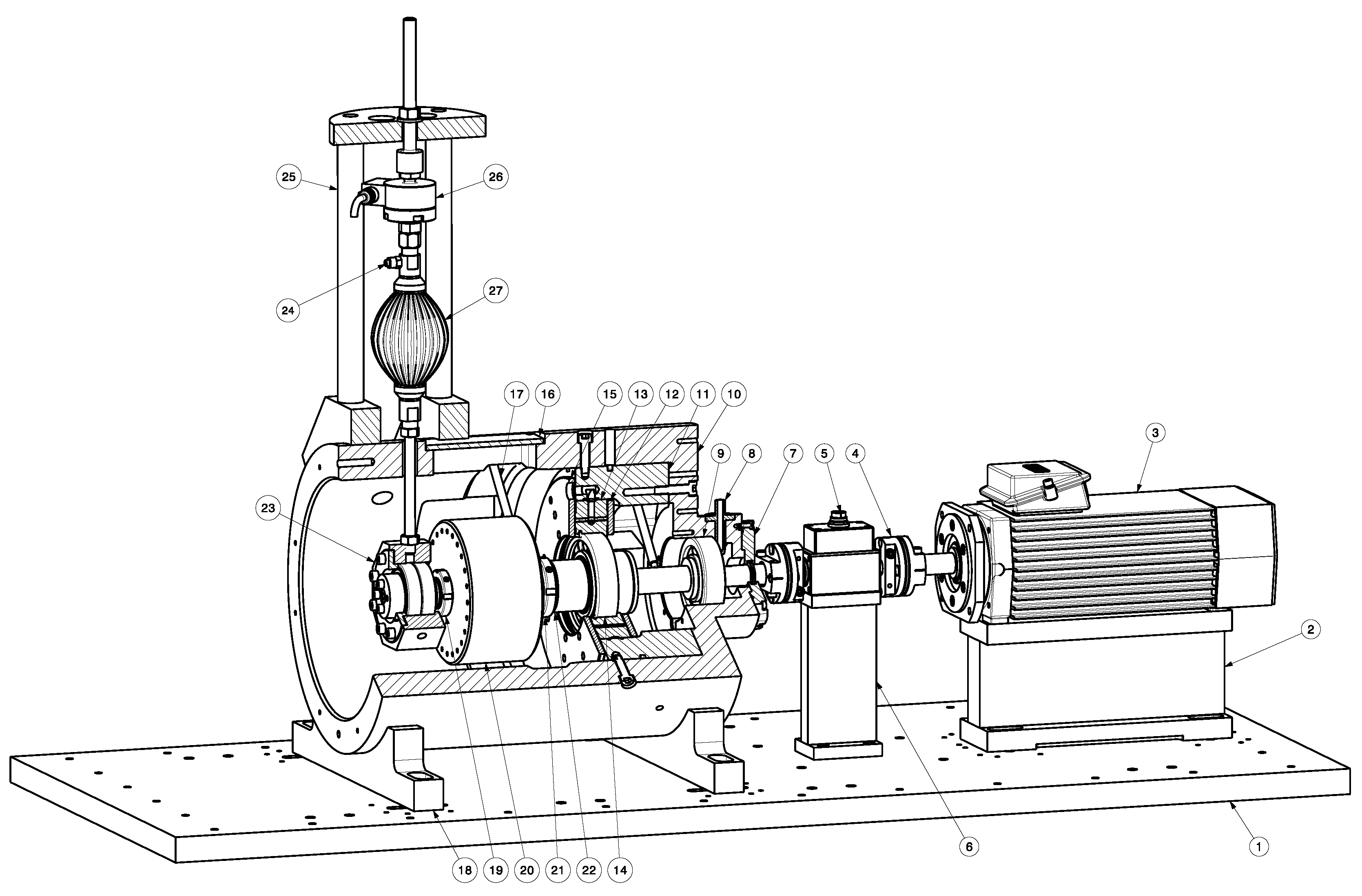
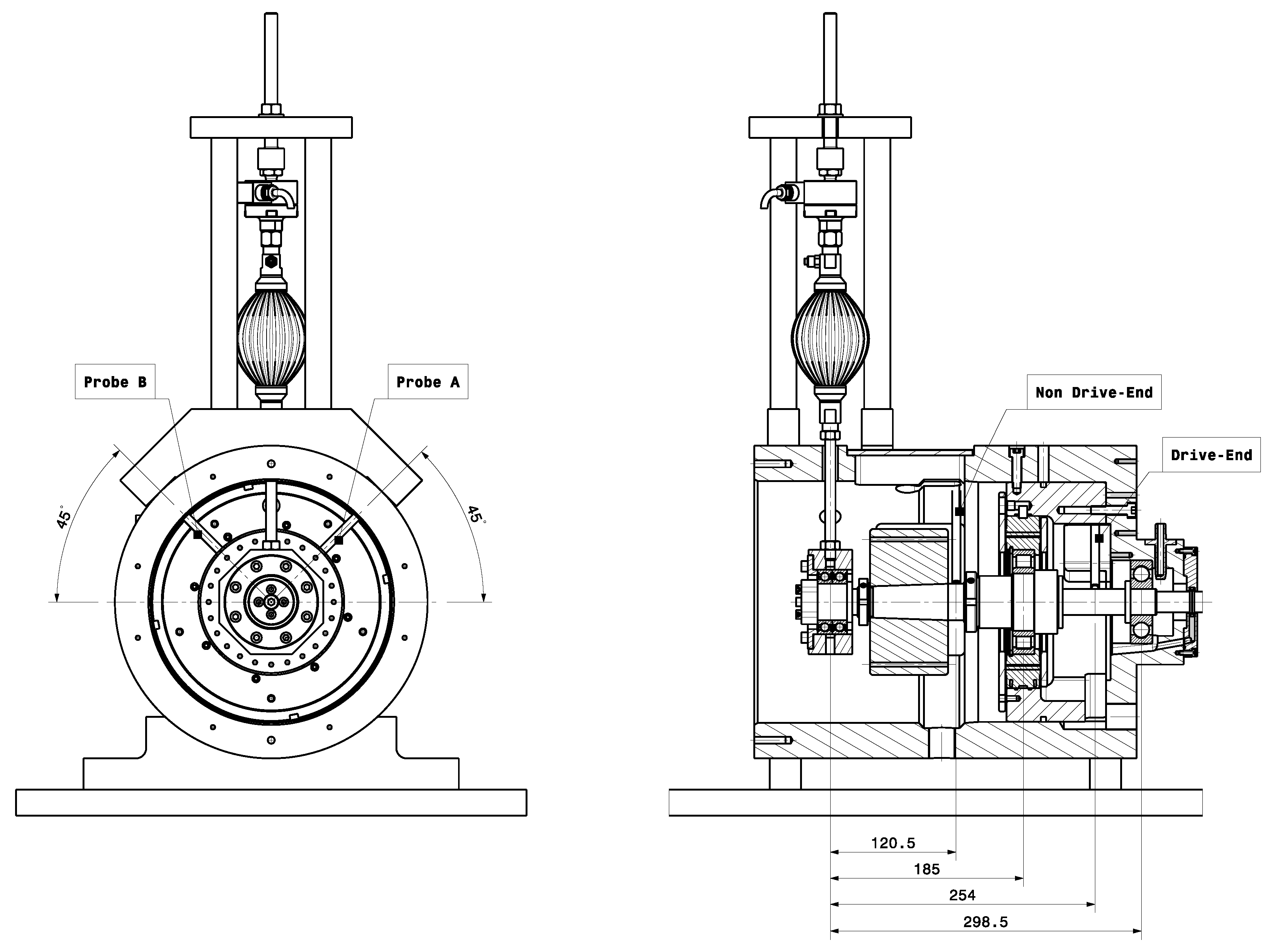
4.1. Test Rig Design

By evaluating the damped rotor support as a complete system, valuable information on the performance in the actual application becomes readily available. However, few academic test rigs exist that can perform such vital evaluation. Most often, the components are analyzed separately via specialized bearing [17] or damper test rigs [5,9,10].
As a result, an academic setup is developed which can provide an in-depth analysis on the dynamic interaction between the key components of a damped rotor support. Machine components of interest can be investigated in a more controlled setting prior to their introduction in an actual application. Moreover, because of a highly modular design, a wide range of rotor supports can be properly examined. A schematic representation of the test rig is presented in Figure 8 and brief description is given in the next paragraph.
A variable speed electric motor drive (3) allows an overhung supported rotor (22) on rolling element bearings to speed up to 18,000 rpm. The bearing at the drive end side (9) is a permanent one, while the non-drive-end bearing (14) is of modular intent. Although modularity and accuracy are two opposing factors throughout a design, many precautionary measures were taken to deal with this issue. Due to an interchangeable cartridge design for the housing (11) and a cone-based design for the rotor, a large bearing size range, different bearing and damper types can be tested. The assembled cartridge (11) can be instrumented with diverse measurement sensors; for instance, thermocouples, strain gauges, pressure transducers, vibration sensors and so on. In addition, both static and dynamic forces can be applied to the system. The desired static radial and/or axial load (not shown in Figure 8) can be applied indirectly on the rotating bearing inner ring. By using an artificial muscle [18] as actuation system, the stiffness value can be kept sufficiently low in order to decouple the dynamics of the rotor from the loading system. Furthermore, the inherently low component damping of the artificial muscle is essential to accurately estimate the component damping of the SFD. In addition, the dynamic loading can be obtained in two various ways. The most convenient way to generate a controlled unbalance force is to accurately balance the rotor before mounting a precise mass on a particular eccentric position. The second technique of establishing a controlled excitation orbit by two perpendicular positioned electrodynamic shakers is more common practice [9,10]. To cope with more industrially related evaluation requirements, the first technique is of primary interest.

4.2. Measurement Procedure

After fitting the rotor system into the test rig, the loading system and measurement equipment are mounted. To capture the rotor displacement during run-up or coast-down, four inductive proximity probes are installed. Each sensor location and designation is given in Figure 9. Additionally, a static load cell is able to accurately measure the applied radial force. The inlet oil pressure, flow, and temperature are acquired using a pressure gauge, flow meter, and thermocouple, respectively.
When the desired radial load is applied, the run-out is measured at a rotational speed of 600 rpm and compensated for. Next, via the influence coefficient method, the rotor is balanced using one selected plane. As a result, a controlled dynamic unbalance force can be applied by adding precisely determined weights.
To get a suitable reference framework, the vibration response is measured for an oil starved damper-bearing state. Mapping the performance of the damper is, therefore, eased by estimating the damping values of the dry reference conditions. Next, the vibration response is measured with the damper active. So, the oil is heated up to its operational temperature of around 50   C before being fed into the damper. The dynamic unbalance is set to a harsh loading condition, namely 120 gmm, which resembles an ISO 1940 G9 balancing class. The radial load is gradually increased, ranging from 1.4 kN to 4.8 kN. After completing a transient run-up measurement and processing the acquired data via the virtual probe rotation method [2], the single DOF peak-picking technique is applied to estimate the corresponding damping values.

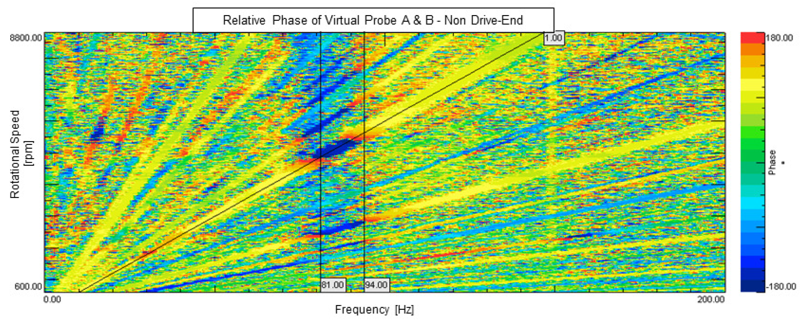
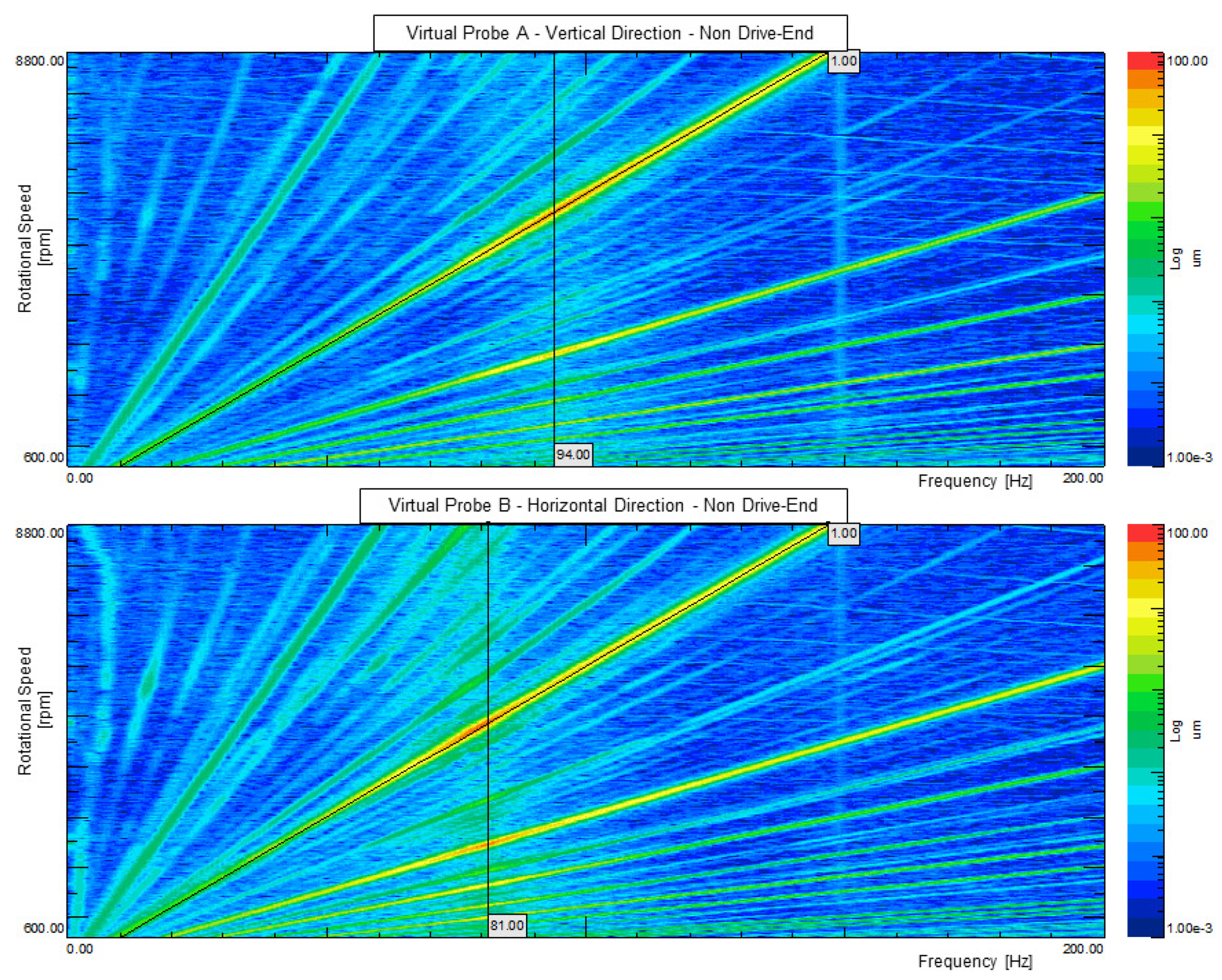
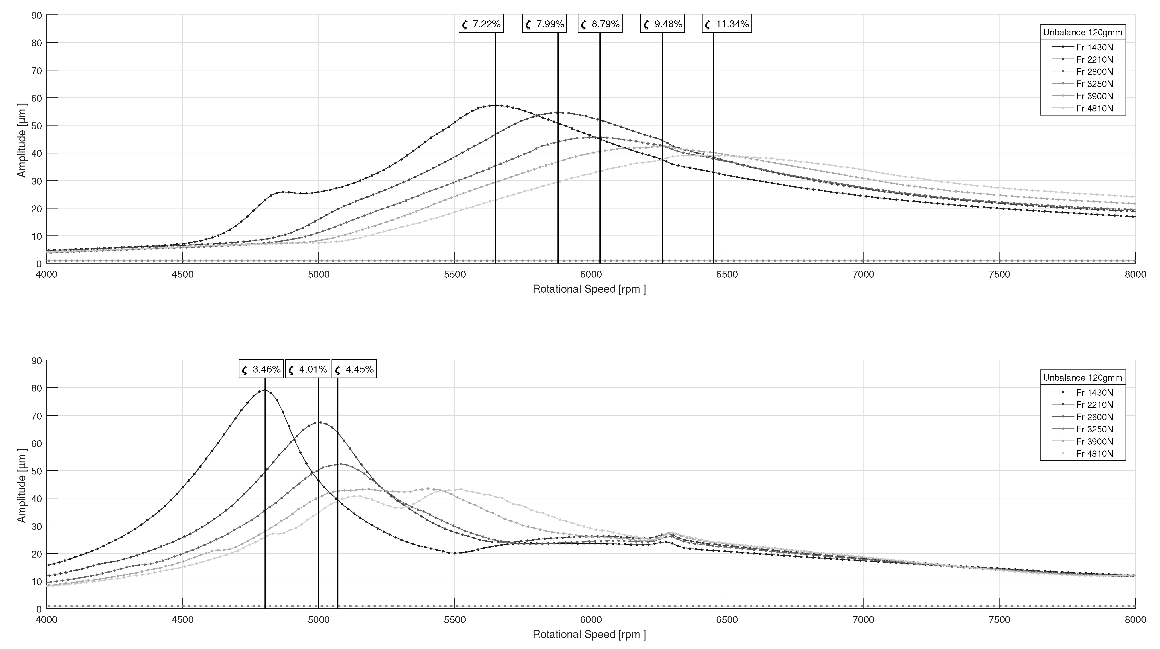
4.3. Experimental Results and Discussion

Figure 10 presents the vibration response data of the performed measurements for the rotor support geometry in Table 2 and with the test conditions given in Table 4.
As expected, both the vertical (Figure 10 top) and horizontal (Figure 10 bottom) direction exhibit a stiffness increase when enlarging the static radial load. However, in terms of the damping, a severe difference can be noted for the lower static loading range. Since a less properly defined stiffness situation arises in the horizontal direction for the CRB, most vibrational motion is present in the bearing itself rather than the damper. As a result, the damper does not function well, causing excessive vibrational levels. It is important to stress that serious vibration problems can arise at the turbomachine’s low power range due to this operational condition with the lightly loaded CRB. Furthermore, during a nearly unloaded run-up of a high power range turbomachine, the CRB can be ill-conditioned as well.
To prove the vertical and horizontal aligned modes represent the first forward and backward whirl modes of the rotor system, respectively, the measurement result set asks for further processed. In particular, the lowest static load case ( 1.4 kN) is used to create the color map of the mutual phase relation between both measurement probes (Figure 11) and the color map of the vibration amplitude (Figure 12).
The mutual phase relation expresses the phase of the vertically oriented Virtual Probe A referenced to the horizontally oriented Virtual Probe B. Since the probes are positioned 90 with respect to each other, an unbalance excitation induces a 90 phase lead. As a result, the first order excitation line colors yellow in Figure 11. However, when approaching the backward mode at 81 Hz, Probe B will shift phase while Probe A remains the same. This results in a switch of the mutual phase sign. When crossing the forward mode, the situation restores again to a 90 relative phase lead. Likewise, the background noise will induce a clear negative mutual phase (blue) when exciting the backward mode and a positive phase (red) for the forward mode [2].
On the top graph of Figure 12, around 94 Hz, a resonance appears rather indistinctly in the background. As concluded before, this vertically manifested mode resembles the first forward whirl mode. On the contrary, for the bottom graph, a resonance explicitly comes forward around 81 Hz. This mode features the first backward whirl mode, which seems to be less damped and is triggered by a forward excitation source, namely the unbalance load, due to the asymmetric stiffness of the CRB.
To the extent of resolving the performance issue for the lower loading range, the most trivial solution would be to lower the stiffness of the damper. However, due to several operational restrictions, for instance static misalignment, this is not a feasible option. Another solution would be to adjust the housing to an oval shape, whereas the CRB is radially preloaded in the direction of the minor stiffness axis. Likewise, the housing can be machined slightly undersized to radially preload the complete CRB in order to create a clearance-free CRB operating condition. However, the latter two solutions can be hazardous since an accurate knowledge of the bearing thermal management is of vital importance. Besides, developing an alternative bearing setup based on axially preloaded deep groove (DGBB) or angular contact (ACBB) ball bearings can most likely address the problem. However, this solution will be more expensive and could give rise to bearing lifetime problems due to excessive radial load for the higher power variant.

5. Conclusions

This work examines the performance of a damped rotor support, comprising a CRB positioned in series with a SFD, over a large static loading range. A numerical and experimental study is carried out using sophisticated calculation tools and a specially designed rotor dynamic test rig. This academic setup allows a detailed investigation of the internal dynamic behavior of the main components in a more controlled environment. In particular, with the help of simulating the rotor dynamics, the test rig rotor is adjusted to fit the dynamics of the anticipated industrial application. Focus, on the other hand, is laid upon the dynamics of the CRB and its influence on the first forward and backward whirl mode.
Three static load cases are selected for the numerical simulations to cover the vast loading range. The results of the damped eigenvalue and forced response analysis revealed certain difficulties when using merely the same CRB for the entire specified static loading range. Especially, the low loading range seems troublesome as a result of the anisotropic bearing stiffness, which causes a split first whirl mode where the backward component is severely triggered by the synchronous unbalance excitation.
As the simulation results marked out some performance issues in the lower loading range, emphasis is laid upon this state during the test series. The expected split resonance emerged when acquiring the transient run-up data for different static radial load amplitudes. Next, the damping ratio was estimated using the single DOF peak-picking method after processing the measurement data with the virtual probe rotation method to cope with the highly elliptical mode shapes. A severe difference in damping capability is once more noted for the low static loading region. So, it is important to solve the vibration problems that can arise at the turbomachine’s low power range due to the lightly loaded CRB. This issue can be resolved by decreasing the damper stiffness, increasing the static load on the CRB or by redesigning the mechanical drivetrain. However, some of the proposed solutions cannot be implemented due to cost or operational restrictions.

Author Contributions

All authors certify that they have participated sufficiently in the work to take public responsibility for the content, including participation in the concept, design, analysis, writing, or revision of the manuscript. More specifically, H.M. conducted the main research work through the conceptualization of the study, design and manufacturing of the test setup, performing the measurements, analyzing the data and justifying the measurement results with the calculations. Finally, H.M. wrote the manuscript. All other authors (J.F., G.V.D.V., B.V., W.D., P.G. and D.L.) analyzed the data and provided advice on both the numerical as well as the experimental part. Furthermore, the manuscript was critically revised for important intellectual content by the co-authors.

Funding

Flanders Innovation & Entrepreneurship Agency (VLAIO) is gratefully acknowledged for its support within the Baekeland-mandate No. 140751 and Research & Development project SCROLL No. 120489. This work also benefits from the Fund for Scientific Research—Flanders (FWO) No. 1S08417N.

Conflicts of Interest

The authors declare no conflict of interest.

Abbreviations

The following abbreviations are used in this manuscript:
ACBBAngular Contact Ball Bearing
CRBCylindrical Roller Bearing
DGBBDeep Groove Ball Bearing
DOFDegree-of-Freedom
ISFDIntegral Squeeze Film Damper
SFDSqueeze Film Damper

References

  1. Vance, J.; Zeidan, F.; Murphy, B. Machinery Vibration and Rotordynamics; John Wiley & Sons, Inc.: Hoboken, NJ, USA, 2010. [Google Scholar]
  2. Bently, D.E.; Hatch, C.T. Fundamentals of Rotating Machinery Diagnostics; Bently Pressurized Bearing Company: Minden, LO, USA, 2002. [Google Scholar]
  3. Mitchell, C.; Schaefer, C.; Graf-Coller, O.; Solfrank, P.; Scheldt, M. Rolling Bearings in Turbochargers: A Real Bargain with Regard to CO2 Emissions. In Solving the Powertrain Puzzle: 10th Schaeffler Symposium; Schaeffler Technologies: Detroit, MI, USA, 2014. [Google Scholar]
  4. Müller, C.; Schuster, P.; Koch, O. Energy Efficiency by using Innovative Bearing Solutions. Power Transm. Eng. 2010, 4, 32–36. [Google Scholar]
  5. Zeidan, F.Y.; San Andrés, L.; Vance, J.M. Design and Application of Squeeze Film Dampers in Rotating Machinery. In Proceedings of the 25th Turbomachinery Symposium, Houston, TX, USA, 17–19 September 1996. [Google Scholar]
  6. Gunter, E.J. Rotor-Bearing Stability. In Proceedings of the First Turbomachinery Symposium, College Station, TX, USA, 24–26 October 1972. [Google Scholar]
  7. Ertas, B.; Cerny, V.; Kim, J.; Polreich, V. Stabilizing a 46MW Multi-Stage Utility Steam Turbine using Integral Squeeze Film Bearing Support Dampers. In Proceedings of the ASME Turbo Expo: Turbine Technical Conference and Exposition, Düsseldorf, Germany, 16–20 June 2014. [Google Scholar]
  8. Cooper, S. Preliminary Investigation of Oil Films for the Control of Vibration; Institution of Mechanical Engineers: London, UK, 1963. [Google Scholar]
  9. Jeung, S.H.; San Andrés, L.; Bradley, G. Forced Coefficients for a Short Length, Open Ends Squeeze Film Damper with End Grooves: Experiments and Predictions. J. Eng. Gas Turb. Power 2016, 138. [Google Scholar] [CrossRef]
  10. San Andrés, L.; Jeung, S.H. Experimental Performance of an Open Ends, Centrally Grooved, Squeeze Film Damper Operating with Large Amplitude Orbital Motions. J. Eng. Gas Turb. Power 2015, 137. [Google Scholar] [CrossRef]
  11. Della Pietra, L.; Adiletta, G. The Squeeze Film Damper over Four Decades of Investigations. Part I: Characteristics and Operating Features. Shock Vib. Dig. 2002, 34, 3–26. [Google Scholar]
  12. Della Pietra, L.; Adiletta, G. The Squeeze Film Damper over Four Decades of Investigations. Part II: Rotordynamic Analyses with Rigid and Flexible Rotors. Shock Vib. Dig. 2002, 34, 97–126. [Google Scholar]
  13. San Andrés, L. Squeeze Film Dampers: Operation, Models and Technical Issues; Turbomachinery Laboratory, Texas A&M University: College Station, TX, USA, 2010. [Google Scholar]
  14. Harris, T.A.; Kotzalas, M.N. Essential Concepts of Bearing Technology, 5th ed.; Taylor & Francis: Boca Raton, FL, USA, 2006. [Google Scholar]
  15. De Mul, J.M.; Vree, J.M.; Maas, D.A. Equilibrium and Associated Load Distribution in Ball and Roller Bearings Loaded in Five Degrees of Freedom while Neglecting Friction—Part I: General Theory and Application to Ball Bearings. Trans. ASME Tribol. Conf. 1989, 111, 149–155. [Google Scholar] [CrossRef]
  16. Andréason, S. Load Distribution in a Taper Roller Bearing Arrangement considering Misalignment. Tribology 1973, 6, 84–92. [Google Scholar] [CrossRef]
  17. Jacobs, W. Experimental Analysis of the Dynamic Characteristics and Lubricant Film of a Ball Bearing under Combined Static and Dynamic Load. Ph.D. Thesis, KU Leuven, Leuven, Belgium, 2014. [Google Scholar]
  18. Verrelst, B. A Dynamic Walking Biped Actuated by Pleated Pneumatic Artificial Muscles: Basic Concepts and Control Issues. Ph.D. Thesis, Vrije Universiteit Brussel, Brussel, Belgium, 2005. [Google Scholar]
Figure 1. Schematic overview of an integral spring squeeze film damper.
Machines 07 00014 g001
Figure 2. Discretized model for rotor dynamic numerical study.
Machines 07 00014 g002
Figure 3. Load distribution of the CRB for three static load cases. The transmitted radial load is directed vertically upwards.
Machines 07 00014 g003
Figure 4. Results of the performed damped eigenvalue analysis for the 1050 N load case.
Machines 07 00014 g004
Figure 5. Results of the performed damped eigenvalue analysis for the 2380 N load case.
Machines 07 00014 g005
Figure 6. Results of the performed damped eigenvalue analysis for the 7000 N load case.
Machines 07 00014 g006
Figure 7. Amplitude vibration response plot for the selected quasi-static load cases.
Machines 07 00014 g007
Figure 8. Technical drawing of the novel rotor dynamic test rig.
Machines 07 00014 g008
Figure 9. Locations of the proximity sensors (dimensions in mm).
Machines 07 00014 g009
Figure 10. Amplitude response plot for the rotor system with damper active under 120 gmm unbalance excitation and increasing radial loading. The top graph resembles Virtual Probe A in vertical direction and the bottom graph depicts Virtual Probe B in horizontal direction.
Machines 07 00014 g010
Figure 11. Orbital relative phase plot between Virtual Probes A and B.
Machines 07 00014 g011
Figure 12. Color map of the active damper condition for the 1.4 kN static load case with 120 gmm unbalance excitation.
Machines 07 00014 g012
Table 1. Additional mass, polar inertia and stiffness properties.
m (kg)Ip (kg m2)Kxx (N/m)Kyy (N/m)
Radial Loading System2.26/8.29 ×   10 3 8.29 ×   10 3
Unbalance Disc8.4021.0 ×   10 3 //
Rotor Support—CRB0.7074.6 ×   10 5 Section 3.3Section 3.3
Rotor Support—SFD1.56/Section 3.2Section 3.2
Undamped Bearing//1.00 ×   10 8 1.00 ×   10 8
Table 2. Geometric properties of the rotor support.
CRBType (-)NU 211SFDType (-)ISFD
Inner Diameter (mm)55 Inner Diameter (mm)100
Outer Diameter (mm)100 Outer Diameter (mm)165
Width (mm)21 Width (mm)32
Number of Damper Slots (-)3
Mean Damper Slot Diameter (mm)127
Damper Slot Thickness (mm)0.25
Damper Slot Span ( )330
Table 3. Brief summary of the calculated bearing stiffness values for the different static load cases.
Load CaseStatic Load (N)Kxx (N/m)Kxy (N/m)Kyx (N/m)Kyy (N/m)Kyy/Kxx (-)
110503.14  ×   10 7 1.60  ×   10 7 1.60  ×   10 7 3.68  ×   10 8 12
223807.47  ×   10 7 1.42  ×   10 7 1.42  ×   10 7 5.39  ×   10 8 7
370001.76  ×   10 8 7.50  ×   10 6 7.50  ×   10 6 8.06  ×   10 8 5
Table 4. Test conditions.
OilType (-)ISO VG 68
Temperature ( C )50
Pressure (bar)2.3
Flow (L/min)2.5
Loading ConditionsDynamic Unbalance (gmm)120
ISO 1940 Balancing Class (-)G9
Radial Load (kN)1.4–5.0

