2. Materials and Methods
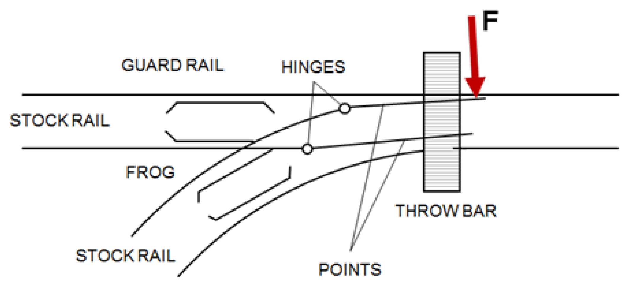
The Alstom RSM object of the present investigation is shown in
Figure 2, along with some balloons highlighting the key structural components of the machine.
Due to confidentiality-related issues, the working principles of the machine cannot be described in detail. The analysis was limited to the verification of the mechanism against unwanted movements of the points caused by a passing train since the system is equipped with two interlocking devices. In fact, once the full stroke has been travelled, and the points are in the open (or closed) position, the switching rod (5) is secured to the body (1) by means of a hammer (4); at the same time, the detection rod (7) is secured to the lower plate (2) by means of a slider, not represented in the picture. Therefore the locking devices come into effect preventing any movement of the rods, when an external force is applied along z-axis to the points, and thereby to the arms (8).
According to the requirements set by railway companies, the RSM should be validated under the action of a force F = 100 kN. The load application rate surely affects the response of the structure. The testing force of F = 100 kN is set by the railway company in order to account for dynamic effects. In order to attain an adequate stiffness of the test fixture, it has been dimensioned for a maximum load of 300 kN. The overall dimensions of the test piece are 900 × 300 × 210 mm; therefore, the fixture was conceived in two separate parts, a lower and an upper grip, so as to achieve a certain flexibility during mounting and unmounting operations on the standing press. In order not to transmit any unwanted bending moment at the arms, the test fixture was shaped as shown in
Figure 3. While the lower grip is a simple C-shaped interface between the actuator thread and the arms, the upper grip has to retain the whole RSM by means of four M20 8.8 class bolts. The bolted joint is doubly overlapped: this provision allows doubling the frictional surfaces and hence the transmissible load for a given bolt size and class [
1,
2]. Except for a few details, the fixture has to be arc welded, therefore a structural steel S275JR according to [
3] has been chosen for its construction. All the welds were statically dimensioned according to Standard EN 1993-1-8 [
4]. In order to assess the stresses and the deformations on the fixture under maximum design load (F = 300 kN), some FEA have been performed by means of the commercial code Ansys Workbench.
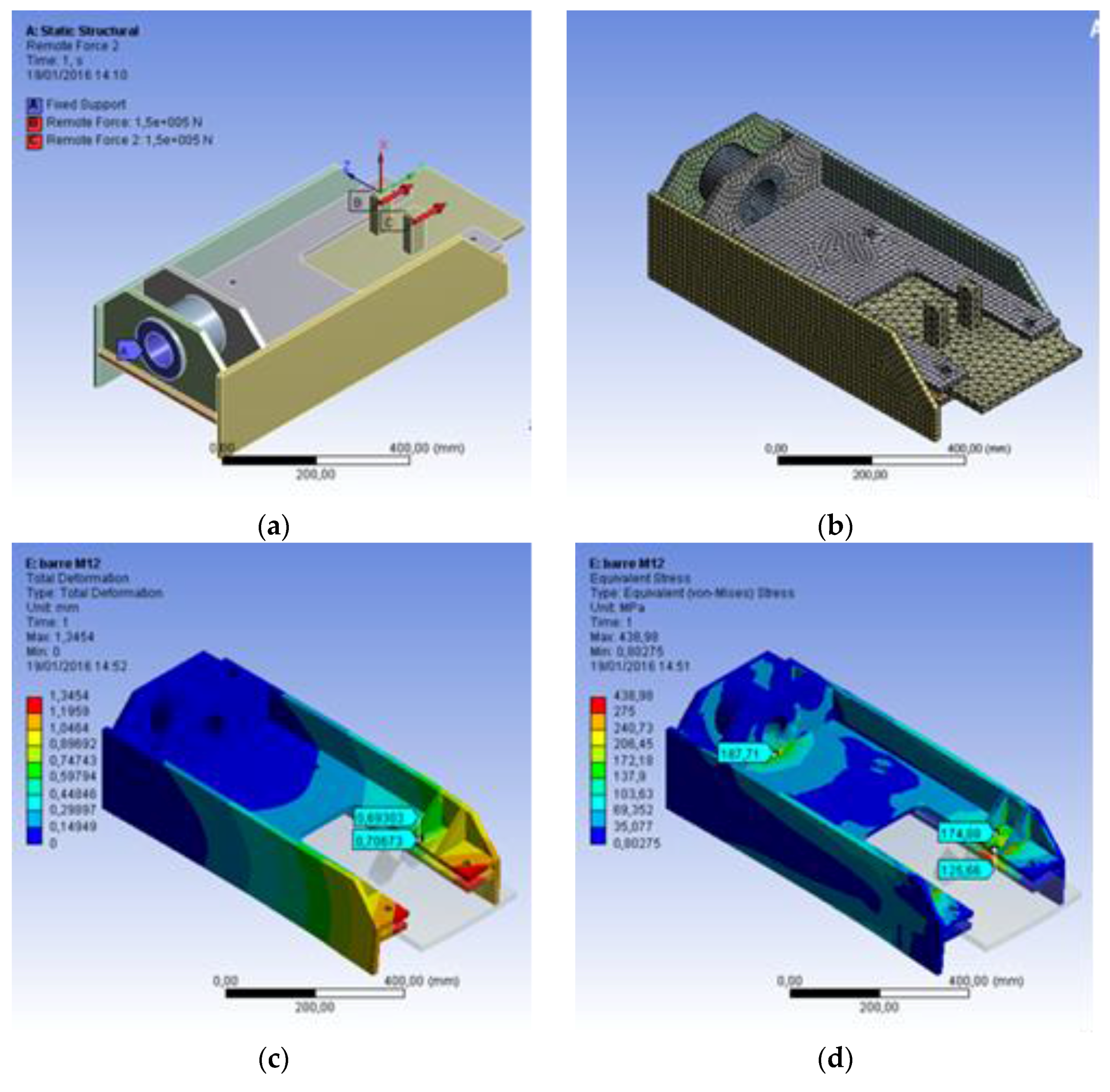
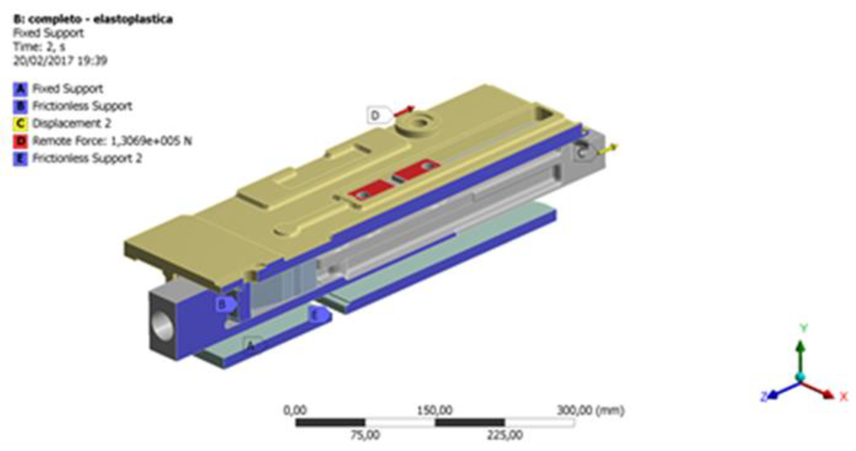
Figure 4a shows the boundary conditions applied to the model: the upper grip has been fixed at the upper end and loaded by two equal forces Fz = 150 kN, one at each arm. The model has been meshed with SOLID187 Tetrahedral and Hexahedral elements,
Figure 4b. The material is a structural steel, whereas the bonded contacts are managed by means of the pure penalty contact algorithm, with the normal stiffness factor set to FKN = 0.01, following the lines suggested by [
5,
6]. The analysis and model parameters are summarized in
Table 1.
As can be appreciated by looking at
Figure 4c, the total deformation is Δtot_max = 1.3 mm, whereas the maximum von Mises equivalent stress remains below 190 MPa (see
Figure 4d); such a stress level is well below the material yield point SY = 275 MPa. Since the model is linear, a maximum deformation of about Δtot_nom = 0.4 mm can be expected at nominal load, which is deemed acceptable.
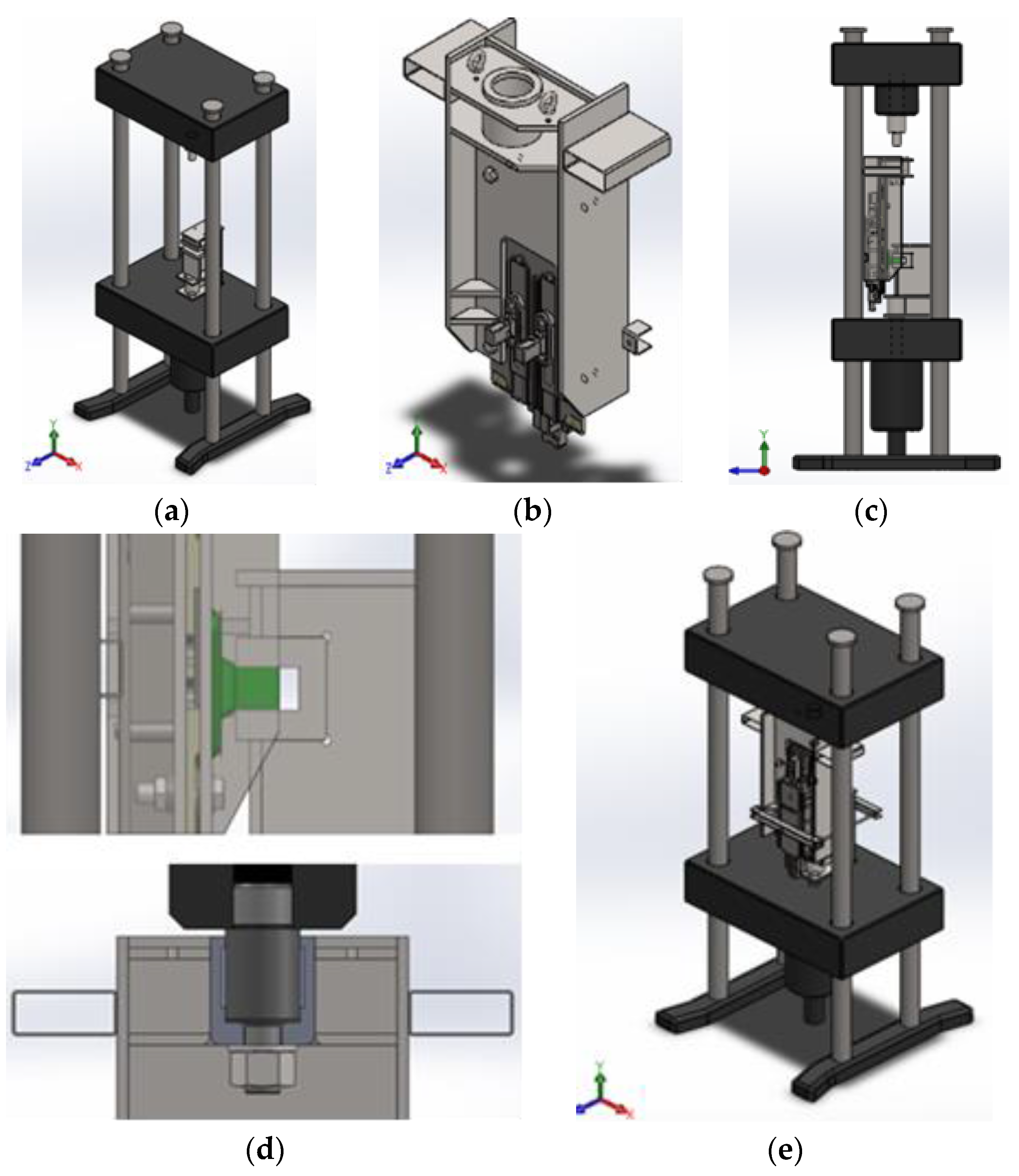
The assembly procedure of the test rig requires quite a number of subsequent operations, briefly summarized in
Figure 5. In particular,
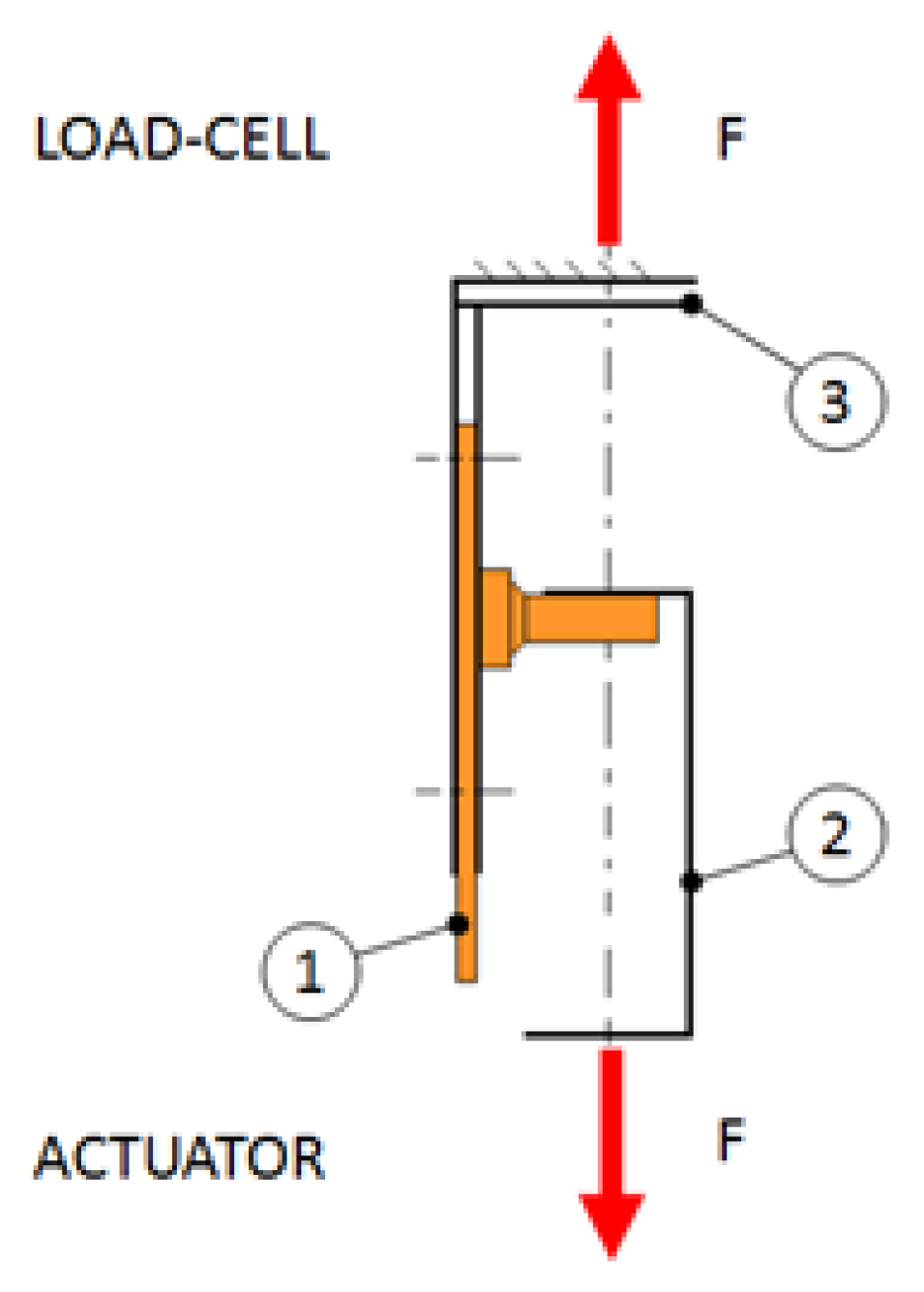
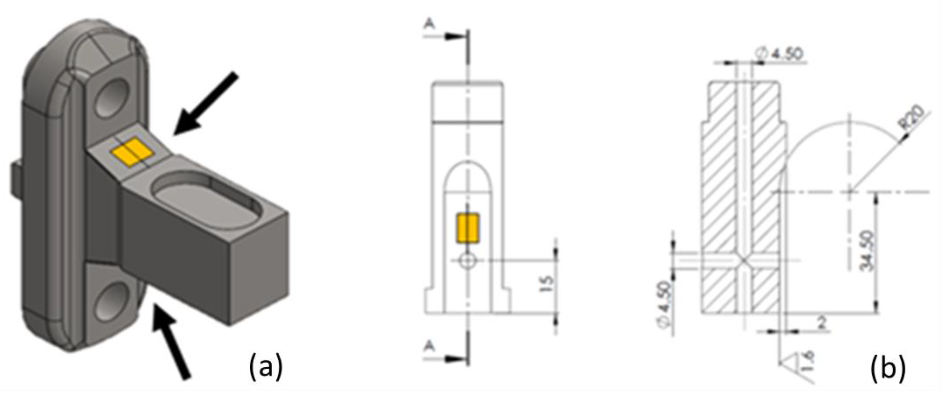
Figure 5d shows a detailed view of the arms of the machine when these are clamped by the lower grip. When the assembly is done, the load cell undergoes zero calibration and the test can begin. The main goal of the experiment is to provide a validation of the FEA models of the RSM that will be described in the following. A secondary aim of the experimentation is to determine how much of the total load is borne by the switching rod and how much by the detection rod. In order to accomplish this twofold task, three components of the RSM were instrumented by strain gauges: the two arms and the pin (see
Figure 6).
The pin and arms had been previously reworked in order to accommodate the sensors (Vishay Precision Group J2A-XXS047K-350); in particular, the pin required both milling and boring operations in order to achieve a plane surface for the application of the strain gauge, as well as a passage for the cables. The arms were instrumented by means of two strain gauges each; the strain gauges were connected in a half-bridge fashion to the Wheatstone circuit. The pin was instrumented by means of a single strain gauge; a dummy gauge, which served as a temperature drift compensator, was glued to an identical, unloaded pin placed in the testing room. The adhesive used for the installation was the M-BOND 200 by Vishay Precision Group. All the sensors were installed by a certified operator, following the guidelines suggested by the Standards [
7,
8,
9]. Data acquisition was managed by means of the NI 9237 sampling card plugged into a NI cDAQ-9184 carrier. The FEA model of the RSM was developed by means of the Ansys code V.17. Due to the complexity of the assembly, submodeling was leveraged, by considering half a model at a time, as if the machine were cut along its mid-plane, normal to the
x-axis. In this way, it was possible to find a satisfactory balance between accuracy and computational cost. Both models were meshed with tetrahedral elements SOLID187, switching rod side (
Figure 7), and detection rod side (
Figure 8). The analysis and model parameters are summarized in
Table 2.
In the case of the switching rod, the stresses on the pin and those on the hammer were sampled, and subsequently compared with the experimental outcomes. In the case of the detection rod, the stresses on the pins that connect the lower plate to the body were examined, as a function of the actual bolt preload of the joint.
3. Results and Discussion
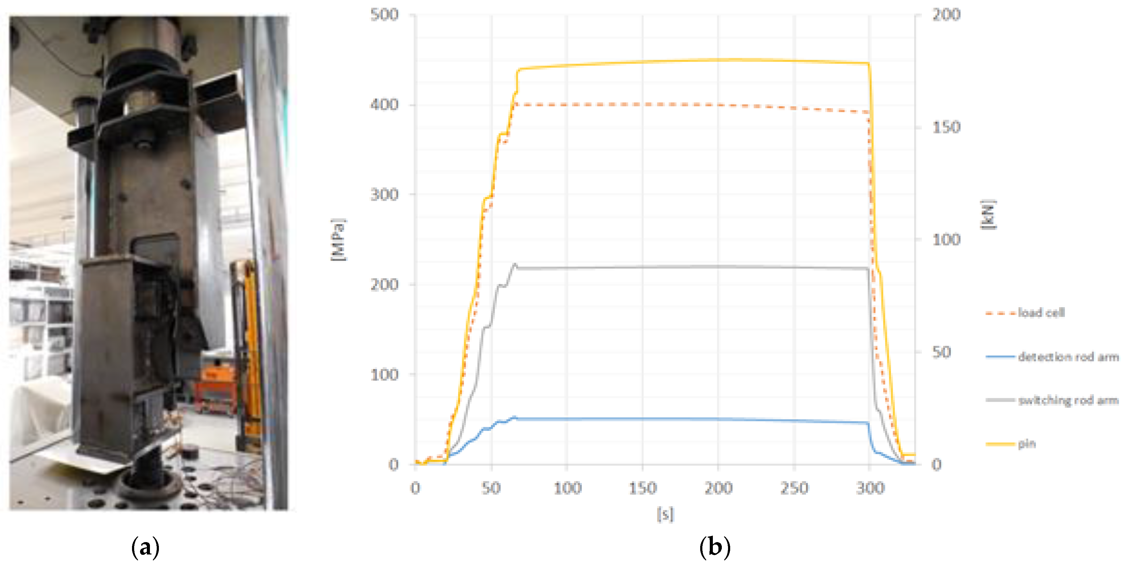
The results from a tensile test carried out on the ad-hoc developed test bench are shown in
Figure 9.
Figure 9 reports the data relevant to a test run until a maximum force of F = 160 kN. At the peak load, one of the pins connecting the lower plate with the body failed. The first outcome of the experiment is the knowledge of the force distribution on the two arms: the great majority of the total force (82%) reaches the body by passing through the chain of components named the switching rod, the pin and the hammer. The remaining part (18%) passes through the detection rod, the slider and the lower plate, eventually reaching the body. Running each of the FEA models by applying the appropriate fraction of the total load to the arm under investigation, it was possible to validate the numerical results. For example, looking at
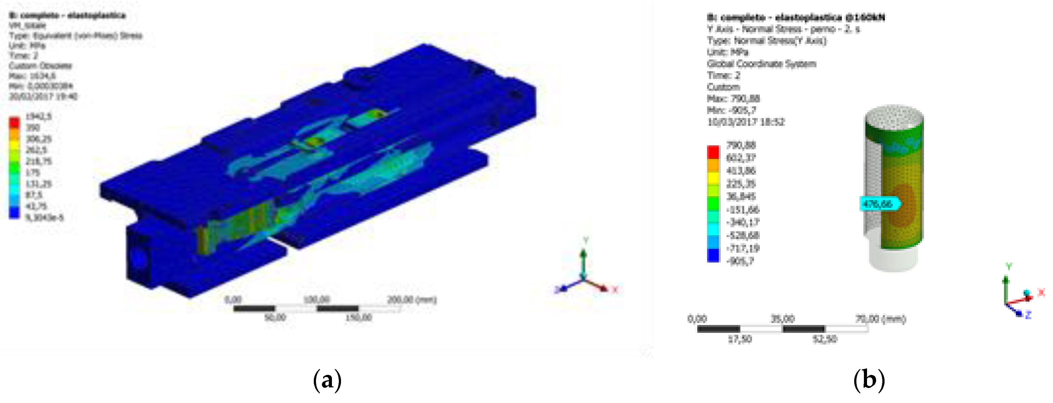
Figure 10a, it is possible to observe the equivalent stresses calculated according to the von Mises criterion on the half machine comprising the switching rod.
Figure 10b reports the σY bending stresses on the pin that supports the hammer, when this sub-system is loaded with 82% the total load F = 160 kN.
As can be appreciated from
Figure 10b, the numerical peak of the bending stress on the pin (σY_FEA = 477 MPa) is very close to that measured during the experimental test on the same component (σY_EXP = 450 MPa, see
Figure 9). The error, calculated according to Equation (1), is acceptable.
Once the FEA model has been validated, it can be used for carrying out some comparisons considering, for example, the joint between the lower plate and the body. Such joints comprise a pattern of eight M8 8.8. screws, working in parallel with a couple of parallel pins of d = 6 mm diameter, manufactured according to Standard [
10]. It can be assumed that this joint must withstand the shearing load transmitted by the slider to the body via the lower plate. These pins are coupled with interference (H7/m6). Since the screws are tightened under preload control upon assembly, and some uncertainties with regard to the friction coefficients cannot be avoided [
11,
12], the load borne by the parallel pins may vary depending on the effective preload of the screws and on the friction coefficient at the interface between the body and the plate. In order to estimate such variation, some parametric analyses were run, for example by imposing different preload levels on the screws. The screw preload was assigned via the preload tool available in the Ansys Workbench environment.
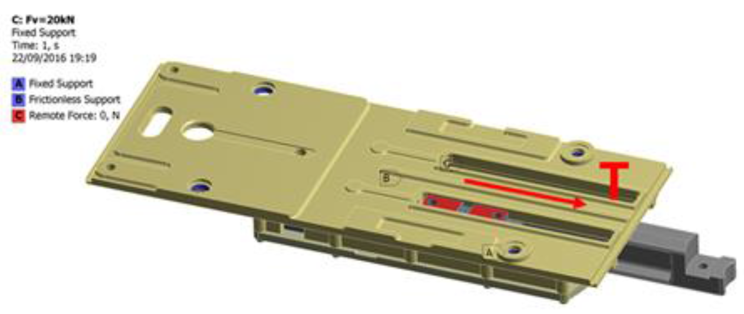
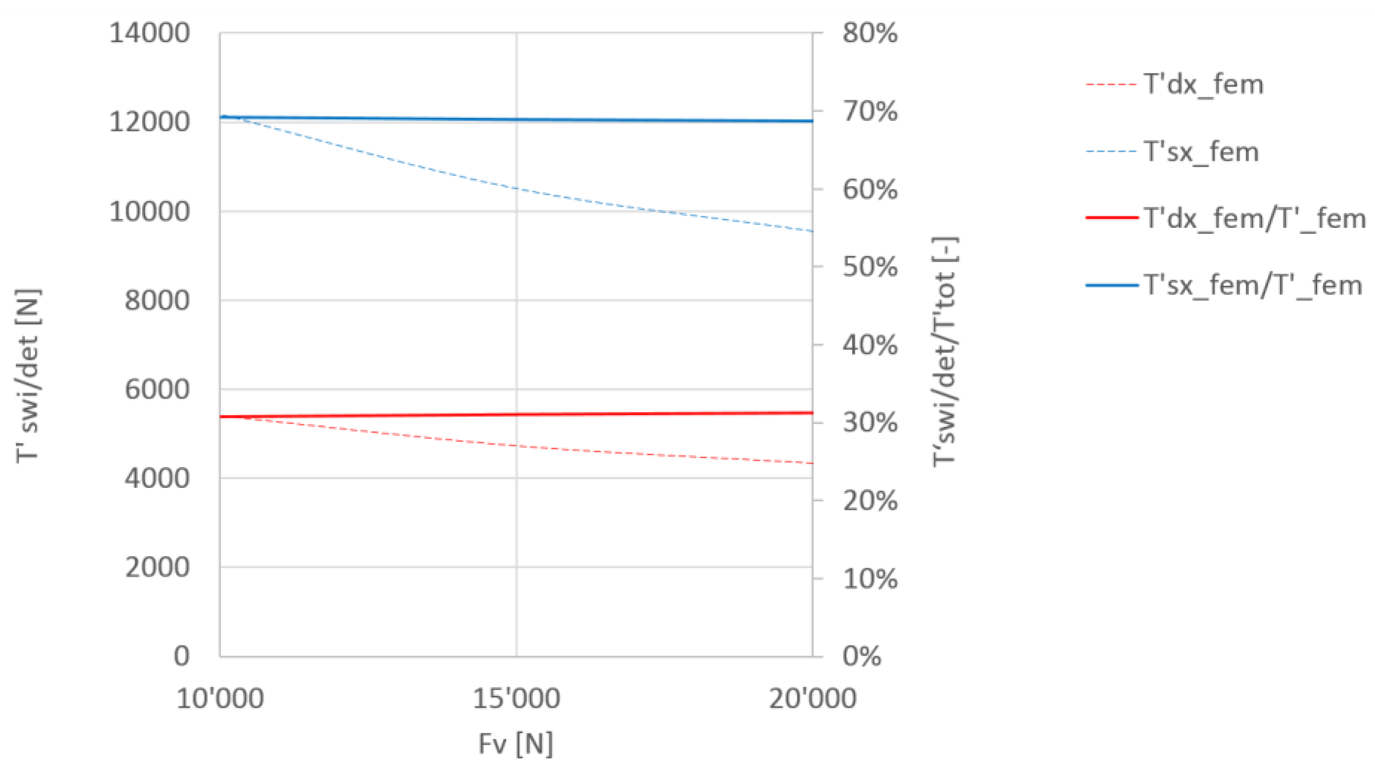
Figure 11 reports a plot of the amount of shearing force borne by the switching rod side pin (T’swi) and by the detection rod side pin (T’det) as functions of the actual screw preload Fv. Each of the dashed lines represents the force acting on the relevant parallel pin, whereas the solid lines represent the fraction of load borne by the generic pin.
It can be seen that the most loaded pin is that on the detection rod side (closer to the slider), regardless of the screw preload. Nonetheless, the magnitude of the load borne by the pins decreases as the screw preload increases: a preload limit of Fv = 20 kN is assumed based on the provisions of Standard [
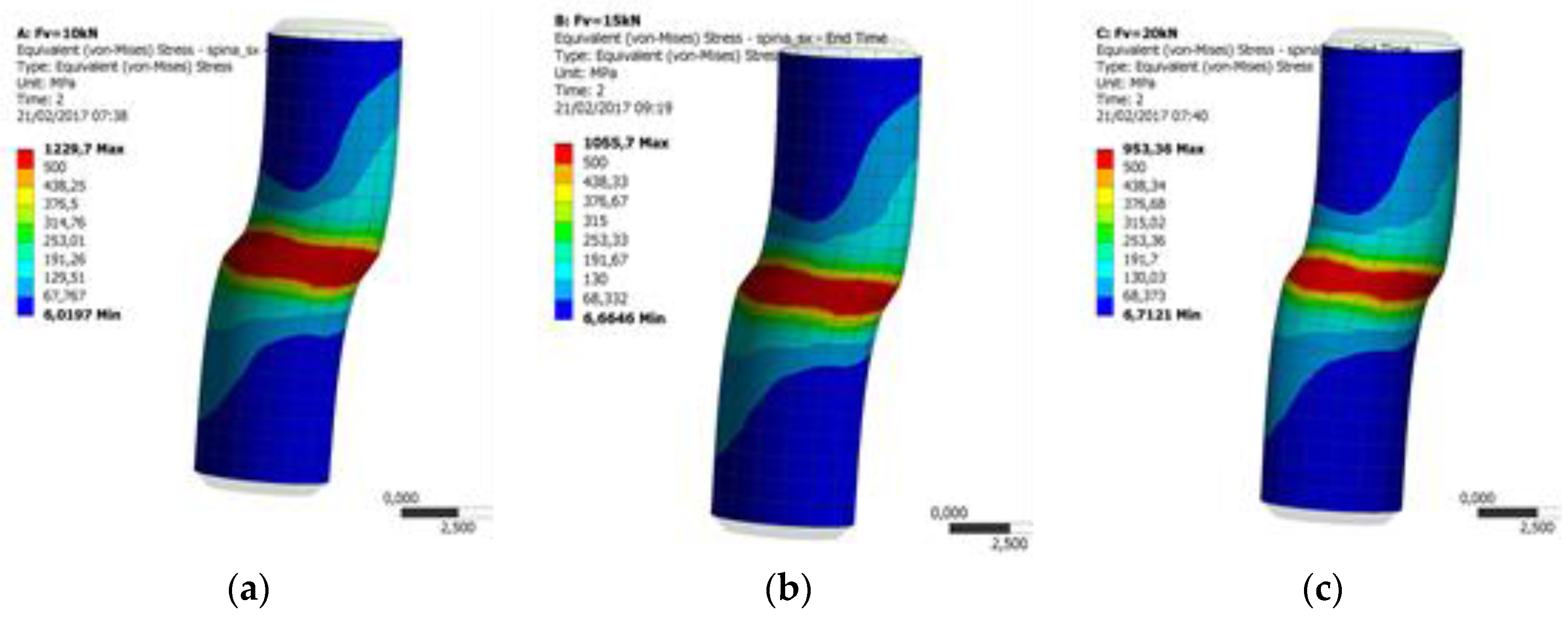
13] for M8, 8.8 class screws. Based on different preload levels, it is also possible to extract a plot of the von Mises stresses on the most loaded parallel pin, as shown in
Figure 12.
The equivalent stress calculated by FEA on the most loaded parallel pin is compatible with the failure event, which took place during the experiment at a total load of F = 160 kN. The strength of the pins could be modified by changing the coupling system, increasing the interference or adopting a different coupling technique. Based on the literature, a valid alternative could be making use of anaerobic or epoxy adhesives, which would make it possible to significantly increase the actual mating area with a positive outcome in terms of the overall strength. This point has been tackled experimentally in papers [
14,
15,
16], which also provide tips regarding the proportioning of the joint upon its design.


