
High-Efficiency Solar-Powered 3-D Printers for Sustainable Development

 , ,
, , 
Abstract
:1. Introduction
2. Methods
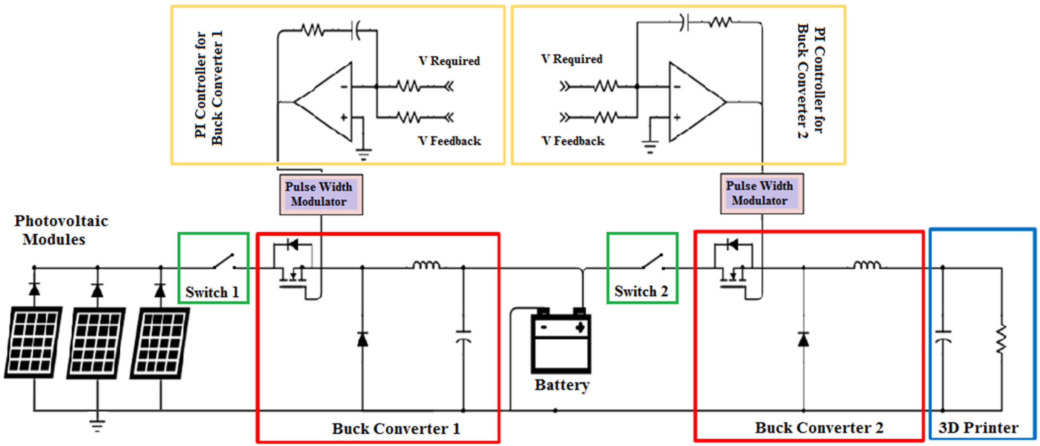
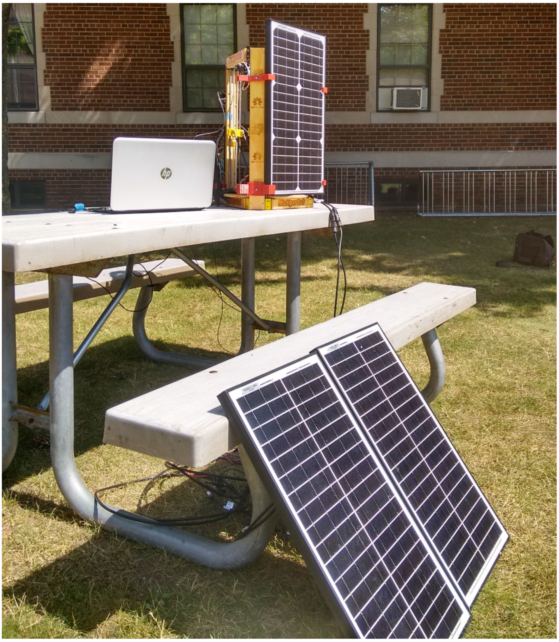
2.1. System Design
- (i)
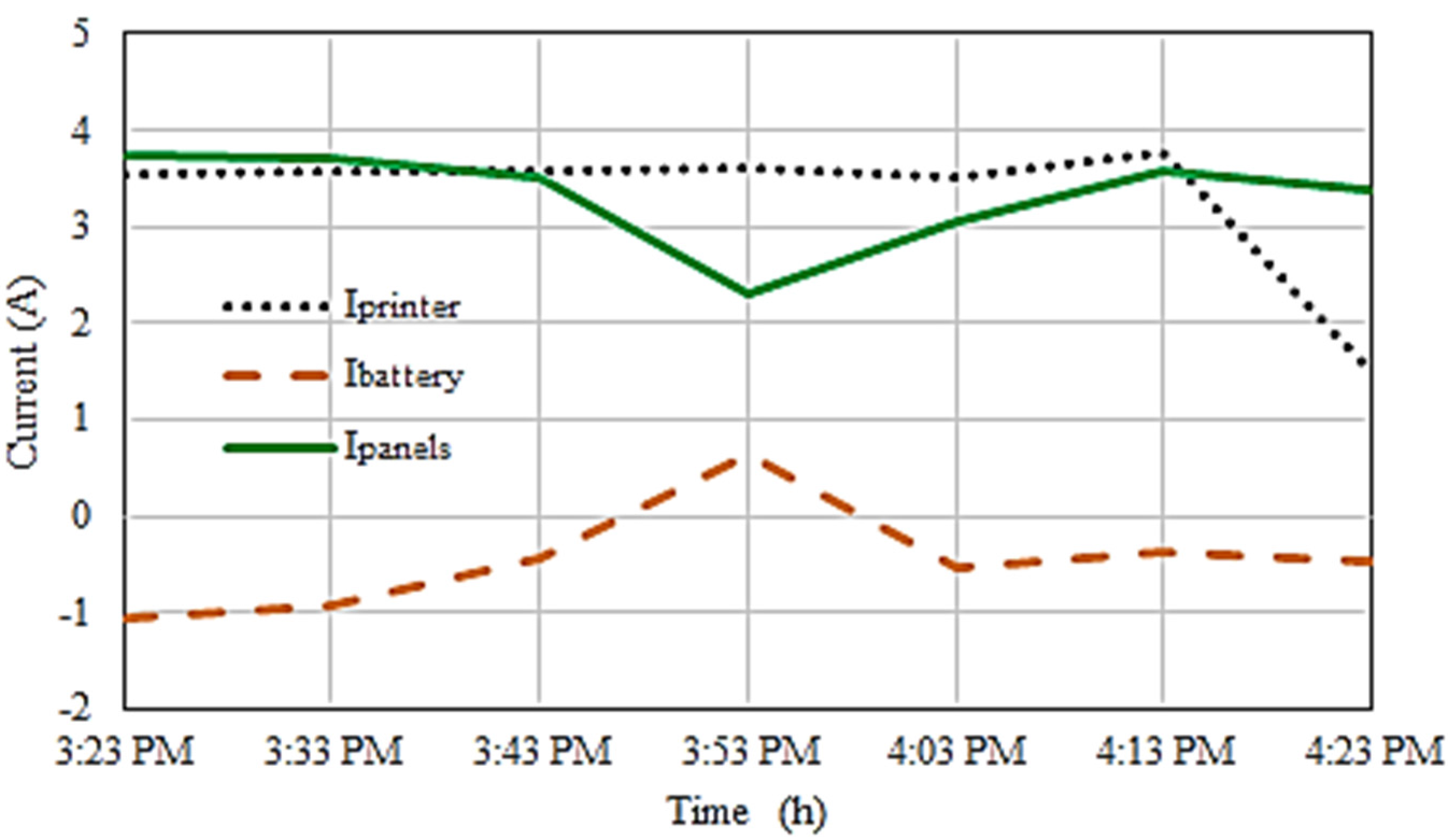
- PV-only mode operation: In this mode, the PV modules supply enough power to meet the 3-D printer energy requirements. It is during this mode that the battery charging occurs, but only during instances when the PV modules power exceeds the printer load.
- (ii)
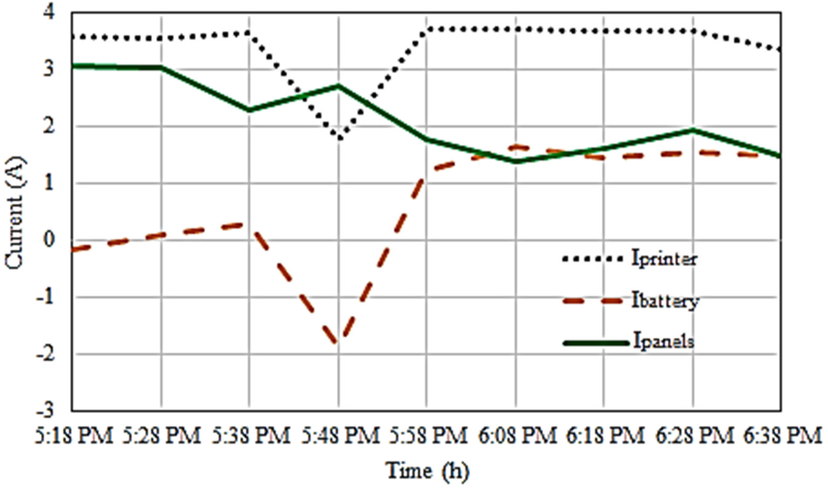
- Mixed-mode operation; Both the PV modules and the battery power the printer. Usually this occurs when the illumination on the PV modules drops to level such that they can no longer provide the required power to drive the load. The battery converter responds by reversing its mode from charge to discharge mode and, by so doing, providing the power needed to compensate for the drop in PV module power.
- (iii)
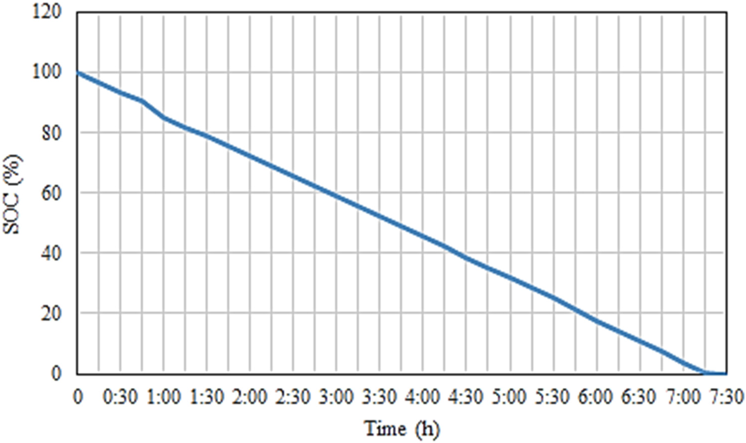
- Battery-only mode: The battery autonomously runs the printer. This happens if printing is done during the night or low light conditions. Total period of autonomy is dependent on the battery size and initial charge, and can be predicted for any system design.


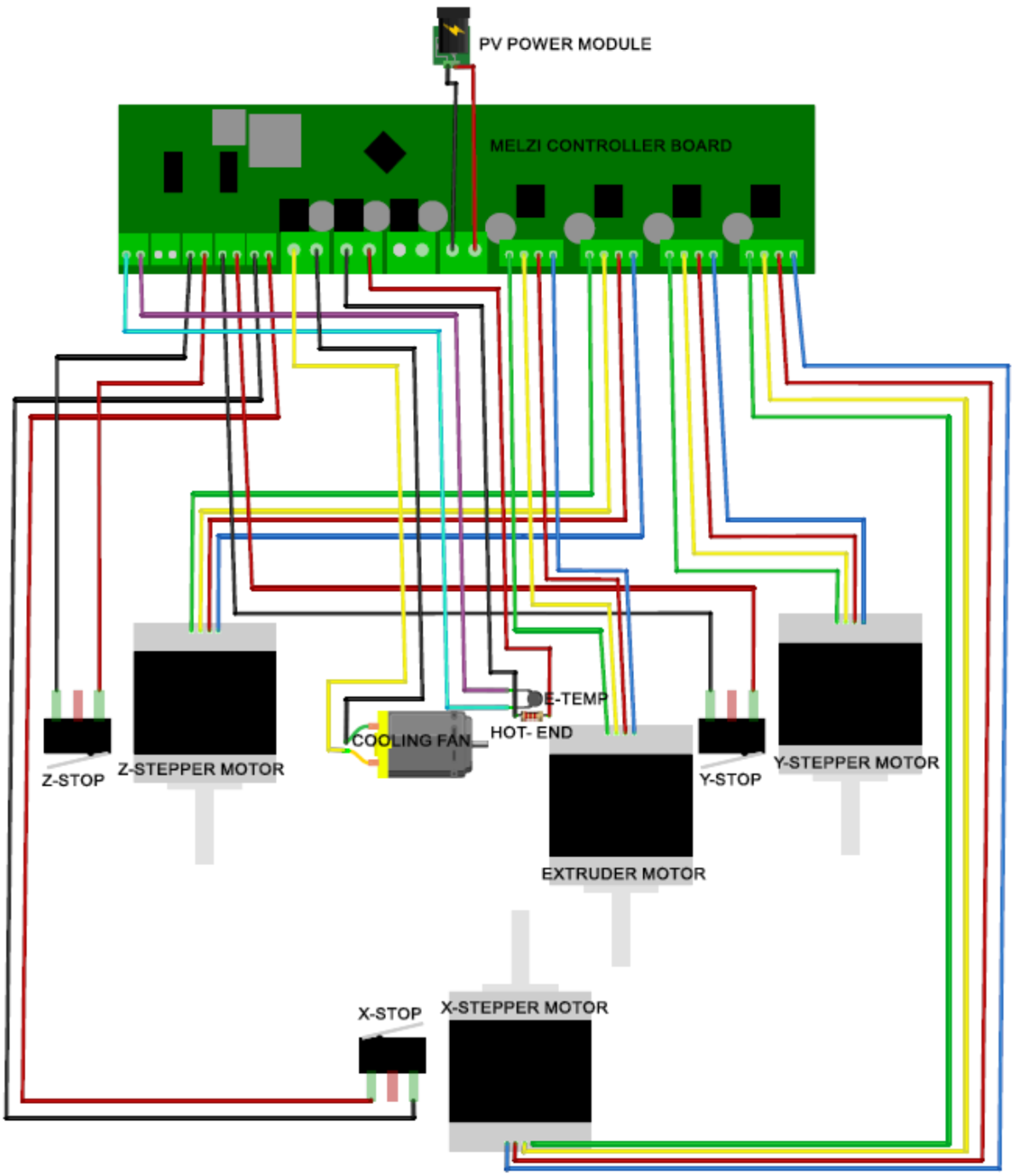
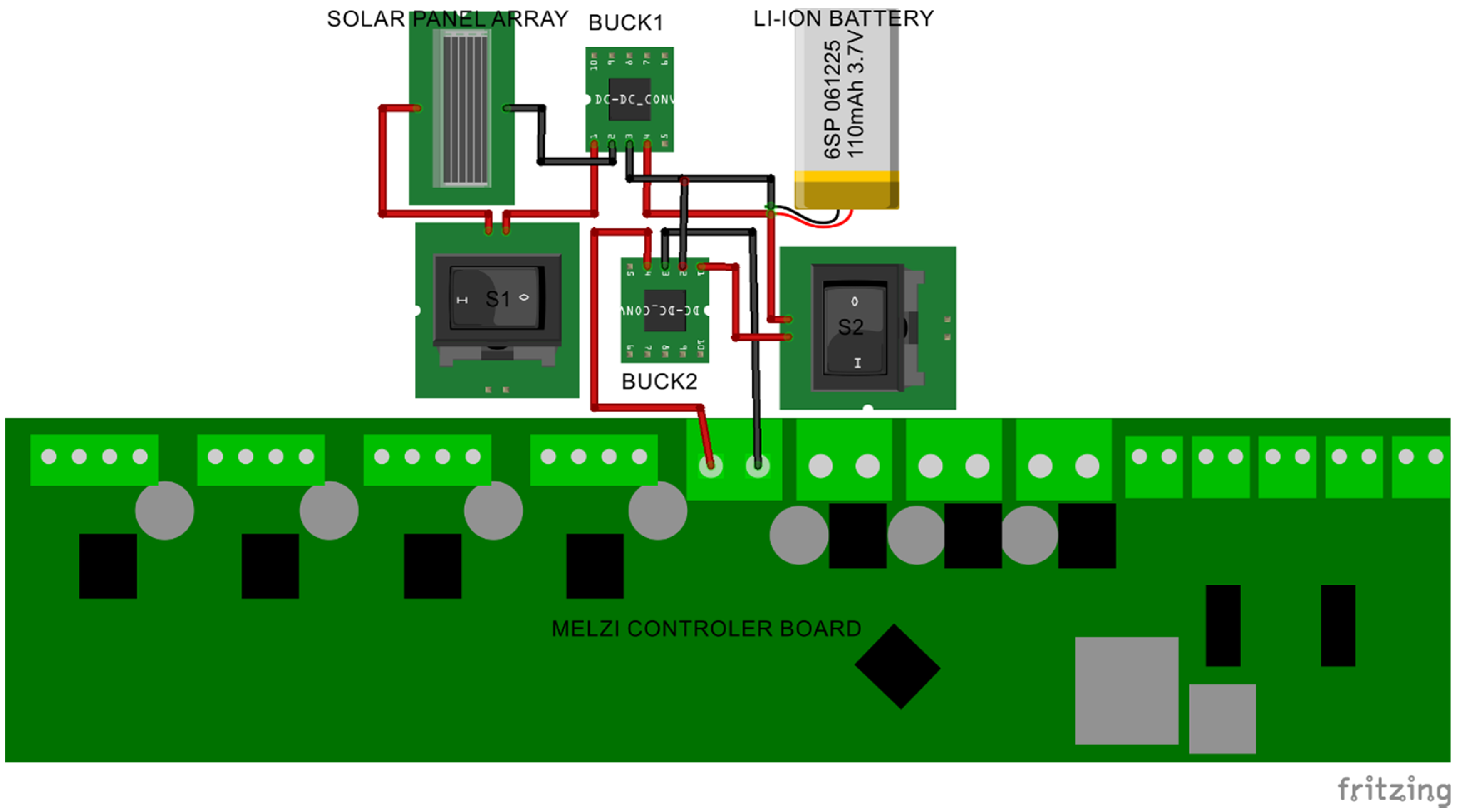
2.2. System Integration

2.3. Experimental Methods
- PV modules charging the battery and driving the 3-D printer.
- System working under low insolation.
- Battery powering the 3-D printer (no PV).
- PV modules charging the battery only (no printing).
- Battery fully charged and the PV modules power the 3D-printer.
3. Results and Discussion


| Switch No. 1 | Switch No. 2 | Tests Performed |
|---|---|---|
| ON | OFF | 4 |
| ON | ON | 1, 2, and 5 |
| OFF | ON | 3 |


4. Conclusions
Acknowledgments
Author Contributions
Conflicts of Interest
Appendix
| Component | Quantities | Source | Cost (US$) |
|---|---|---|---|
| DROK® 12 A/100 W 5–40 V to 1.2–36 V DC Buck Volt Converter | 2 | amazon.com | 21.98 |
| Polymer Li-Ion Rechargeable Battery Pack: 14.8 V 20 Ah (296 Wh) — UN38.3 Passed | 1 | batteryspace.com | 260.00 |
| ALEKO® 30W Monocrystalline Solar Panel | 3 | amazon.com | 197.97 |
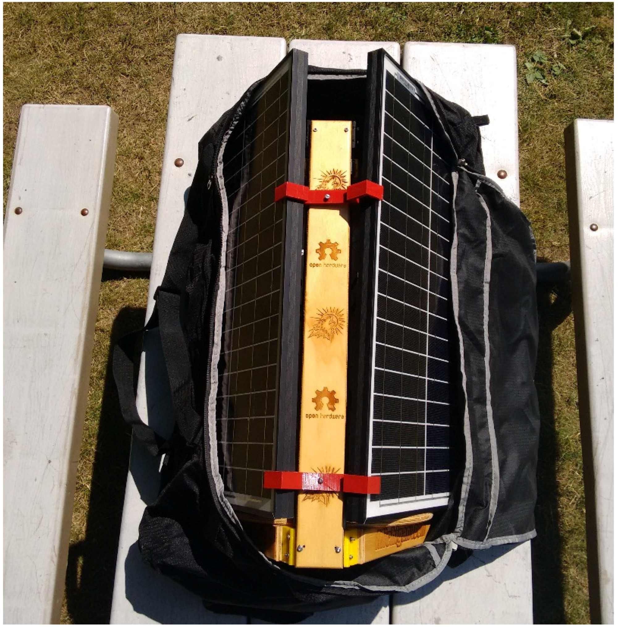
| High Sierra AT2 36" (91 cm) drop bottom wheeled duffel | 1 | amazon.com | 139.99 |
| Bolt with nuts | |||
| 5 Pcs SPST On/Off Momentary Off Rocker Switch AC 250 V/6 A 125 V/10 A | 2 | amazon.com | 4.44 |
| Total | 625.70 | ||
References
- Wong, K.V.; Hernandez, A. A review of additive manufacturing. ISRN Mech. Eng. 2012. [Google Scholar] [CrossRef]
- Allen, R.J.A.; Trask, R.S. An experimental demonstration of effective Curved Layer Fused Filament Fabrication utilising a parallel deposition robot. Addit. Manuf. 2015, 8, 78–87. [Google Scholar] [CrossRef]
- Wohlers, T. Additive Manufacturing Advances. Manuf. Eng. 2012, 148, 55–56. [Google Scholar]
- Wohlers, T. Wohlers Report 2014: 3D Printing and Additive Manufacturing State of the Industry; Wohlers Associates, Inc.: Fort Collins, CO, USA, 2014. [Google Scholar]
- Hunt, E.J.; Zhang, C.; Anzalone, N.; Pearce, J.M. Polymer recycling codes for distributed manufacturing with 3-D printers. Resour. Conserv. Recycl. 2015, 97, 24–30. [Google Scholar] [CrossRef]
- Ladd, C.; So, J.H.; Muth, J.; Dickey, M.D. 3D printing of free standing liquid metal microstructures. Adv. Mater. 2013, 25, 5081–5085. [Google Scholar] [CrossRef] [PubMed]
- Haque, R.I.; Ogam, E.; Loussert, C.; Benaben, P.; Boddaert, X. Fabrication of Capacitive Acoustic Resonators Combining 3D Printing and 2D Inkjet Printing Techniques. Sensors 2015, 15, 26018–26038. [Google Scholar] [CrossRef] [PubMed]
- Anzalone, G.C.; Zhang, C.; Wijnen, B.; Sanders, P.G.; Pearce, J.M. Low-Cost Open-Source 3-D Metal Printing. IEEE Access. 2013, 1, 803–810. [Google Scholar] [CrossRef]
- Haselhuhn, A.S.; Gooding, E.J.; Glover, A.G.; Anzalone, G.C.; Wijnen, B.; Sanders, P.G.; Pearce, J.M. Substrate Release Mechanisms for Gas Metal Arc Weld 3D Aluminum Metal Printing. 3D Print. Addit. Manuf. 2014, 1, 204–209. [Google Scholar] [CrossRef]
- Anzalone, G.; Wijnen, B.; Pearce, J.M. Multi-material additive and subtractive prosumer digital fabrication with a free and open-source convertible delta RepRap 3-D printer. Rapid Prototyp. J. 2015, 21, 506–519. [Google Scholar]
- Lee, B.; Wu, M. Recent advances in 3D printing of tissue engineering scaffolds. Methods Mol. Biol. 2012, 868, 257–267. [Google Scholar] [PubMed]
- Mironov, V.; Boland, T.; Trusk, T.; Forgacs, G.; Markwald, R.R. Organ printing: computer-aided jet-based 3D tissue engineering. TRENDS Biotechnol. 2003, 21, 157–161. [Google Scholar] [CrossRef]
- Sells, E.; Bailard, S.; Smith, Z.; Bowyer, A.; Olliver, V. RepRap: The replicating rapid prototyper-maximizing customizability by breeding the means of production. In Handbook of Research in Mass Customization and Personalization; Pillar, F.T., Tseng, M.M., Eds.; World Scientific: Hackensack, NJ, USA, 2009; Volume 1, pp. 568–580. [Google Scholar]
- Jones, R.; Haufe, P.; Sells, E. Reprap—The replicating rapid prototype. Robotica 2011, 29, 177–191. [Google Scholar] [CrossRef]
- Hedquist, U. Open Source 3D Printer Copies Itself; Self-Replicating Printer Frees-Up 3D Printing under GNU. Available online: http://www.computerworld.co.nz/article/495672/open_source_3d_printer_copies_itself/ (accessed on 13 October 2015).
- Bowyer, A. 3D printing and humanity’s first imperfect replicator. 3D Print. Addit. Manuf. 2014, 1, 4–5. [Google Scholar] [CrossRef]
- Rundle, G. A Revolution in the Making: 3D Printing, Robots and the Future; Affirm Press: South Melbourne, Australia, 2014. [Google Scholar]
- Wittbrodt, B.T.; Glover, A.G.; Laureto, J.X.; Anzalone, G.C.; Oppligerc, D.; Irwin, J.L.; Pearce, J.M. Life-cycle economic analysis of distributed manufacturing with open-source 3-D printers. Mechatronics 2013, 23, 713–726. [Google Scholar] [CrossRef]
- Gwamuri, J.; Wittbrodt, B.T.; Anzalone, N.C.; Pearce, J.M. Reversing the Trend of Large Scale and Centralization in Manufacturing: The Case of Distributed Manufacturing of Customizable 3-D-Printable Self-Adjustable Glasses. Chall. Sustain. 2014, 2, 30–40. [Google Scholar] [CrossRef]
- Pearce, J.M.; Mushtaq, U. Overcoming technical constraints for obtaining sustainable development with open source appropriate technology. In Proceedings of the IEEE Toronto International Conference on Science and Technology for Humanity, Toronto, ON, Canada, 26–27 September 2009; pp. 814–820.
- Pearce, J.M.; Morris, B.C.; Laciak, K.J.; Andrews, R.; Nosrat, A.; Zelenika-Zovko, I. 3-D printing of open source appropriate technologies for self-directed sustainable development. J. Sustain. Dev. 2010, 3, 17–29. [Google Scholar] [CrossRef]
- Pearce, J.M. The case for open source appropriate technology. Environ. Dev. Sustain. 2012, 14, 425–431. [Google Scholar] [CrossRef]
- Alkire, S.; Santos, M.E. Acute Multidimensional Poverty: A New Index for Developing Countries. Available online: http://www3.qeh.ox.ac.uk/pdf/ophiwp/OPHIWP038.pdf (accessed on 14 January 2016).
- Canessa, E.; Fonda, C.; Zennaro, M. Low--cost 3D Printing for Science, Education and Sustainable Development, 1st ed.; ICTP Science Disseminating Unit: Trieste, Italy, 2013; pp. 11–169. [Google Scholar]
- Birtchnell, T.; Hoyle, W. 3D Printing for Development in the Global South: The 3D4D Challenge; Palgrave Macmillan: New York, NY, USA; 2014. [Google Scholar]
- Heyer, S.; Seliger, G. Open manufacturing for value creation cycles. In Design for Innovative Value towards A Sustainable Society; Matsumoto, M., Umeda, Y., Masui, K., Fukushige, S., Eds.; Springer: London, UK, 2012; pp. 110–115. [Google Scholar]
- International Energy Agency. World Energy Outlook: Energy for all 2014. Available online: http://www.worldenergyoutlook.org/resources/energydevelopment/ (accessed on 14 October 2015).
- King, L.D.; Babasola, A.; Rozario, J.; Pearce, J.M. Mobile Open-Source Solar-Powered 3-D Printers for Distributed Manufacturing in Off-Grid Communities. Chall. Sustain. 2014, 2, 18–27. [Google Scholar] [CrossRef]
- Khan, Y.K.; Gauchia, L.; Pearce, M.J. Self-Sufficiency of 3-D Printers: Utilizing Stand-alone Solar Photovoltaic Power Systems. 3D Printed Mater. Syst. 2016, in press. [Google Scholar]
- Irwin, J.L.; Pearce, J.M.; Anzolone, G.; Oppliger, D.E. The RepRap 3-D Printer Revolution in STEM Education. In Proceedings of the 121st ASEE Annual Conference & Exposition, Indianapolis, IN, USA, 15–18 June 2014.
- Melzi. RepRap.org., 2015. Available online: http://reprap.org/wiki/Melzi (accessed on 17 October 2015).
- Sira-Ramírez, H.; Silva-Ortigoza, R. Control Design Techniques in Power Electronic Devices; Springer-Verlag: London, UK, 2006; pp. 13–14. [Google Scholar]
- Blackwelder, J.M.; Dougal, A.R. Power coordination in a fuel cell battery hybrid power source using commercial power controller circuits. J. Power Sources 2004, 134, 139–147. [Google Scholar] [CrossRef]
- Liptak, B.G. Process Control and Optimization; CRC Press (Taylor & Francis Group): Boca Raton, FL, USA, 2006; Volume II. [Google Scholar]
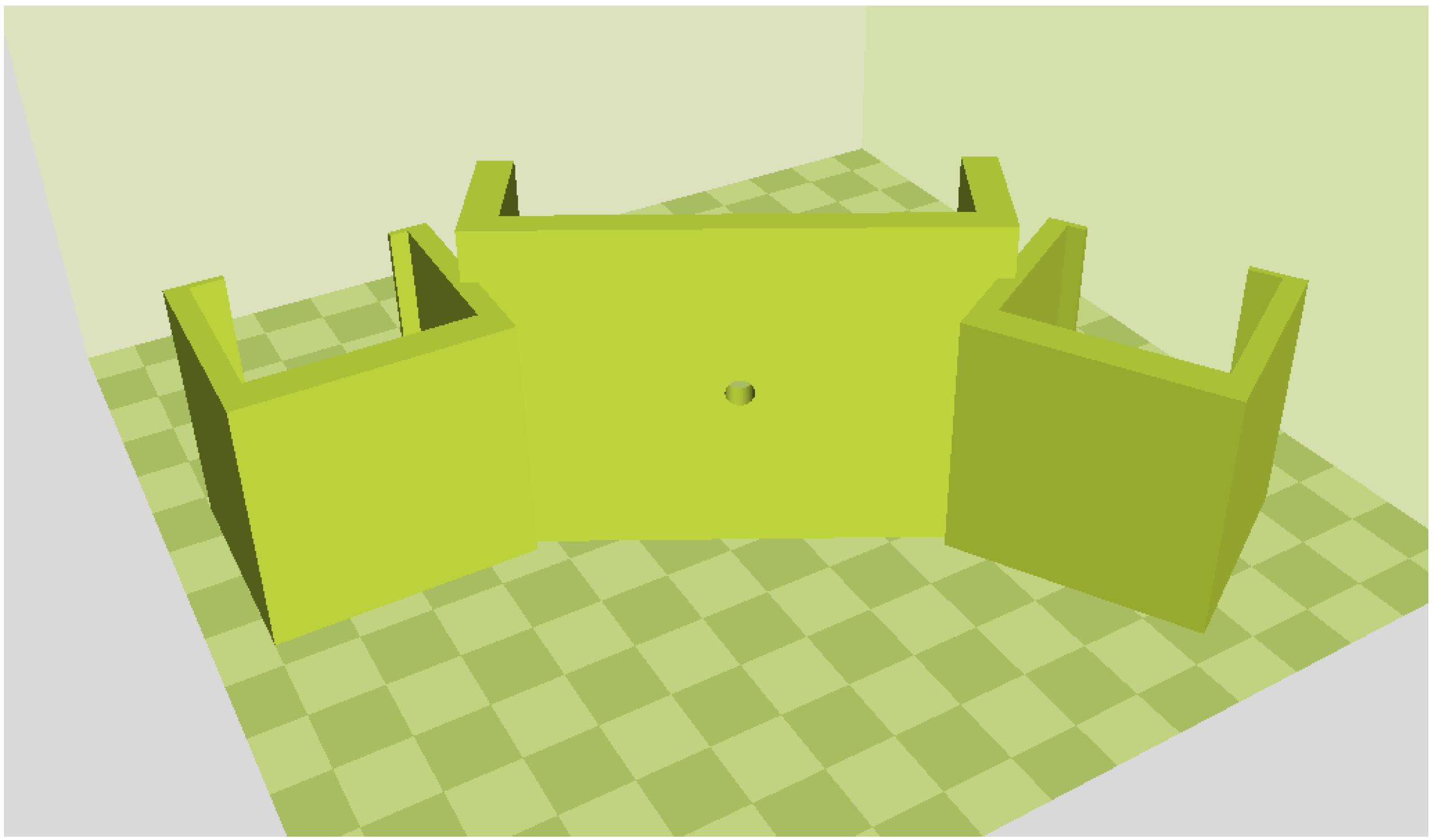
- Gwamuri, J. Solar panel holders (Solar powered 3D printer). Available online: http://www.appropedia.org/Solar_Panels_holders_(Solar_powered_delta) (accessed on 17 October 2015).
- Rocholl, J. Rostock robot 3D printer. Available online: http://www.thingiverse.com/thing:17175 (accessed on 17 October 2015).
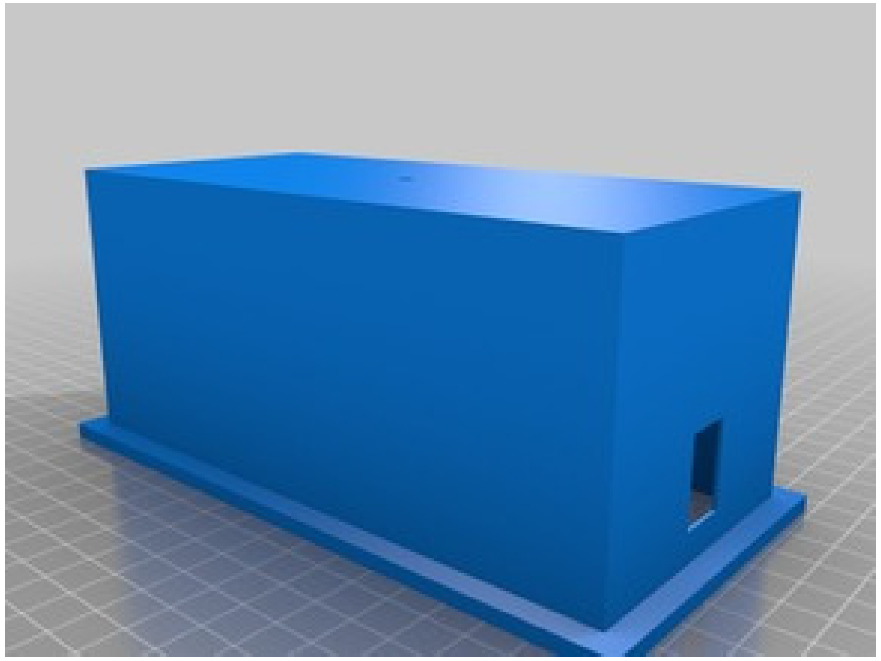
- Printception. Melzi Case. Available online: http://www.thingiverse.com/thing:223013 (accessed on 17 October 2015).
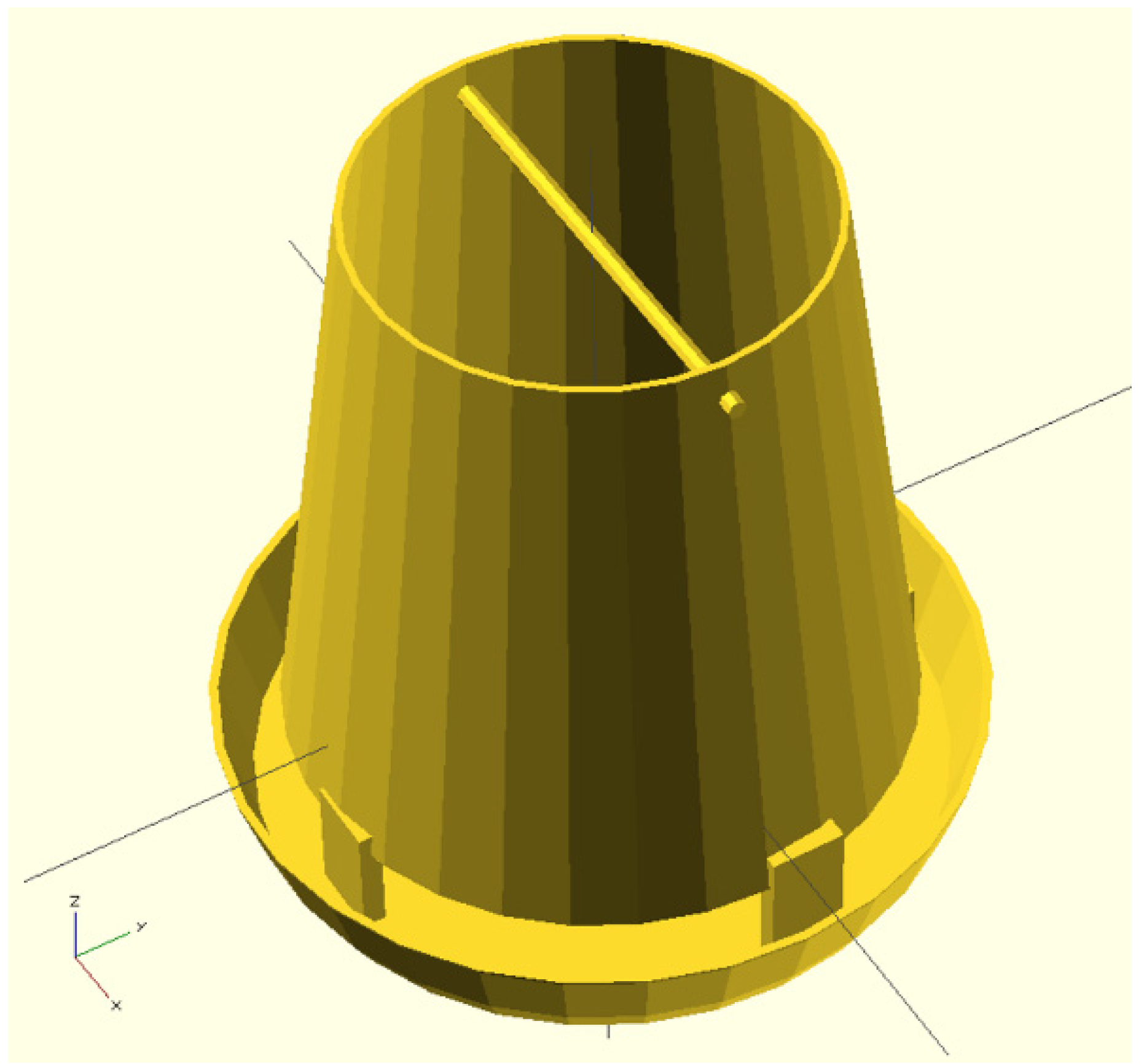
- Gwamuri, J. Chicken Feed Holder. Available online: http://www.appropedia.org/Chicken_Feed_Holder (accessed on 17 October 2015).
- Piller, S.; Perrin, M.; Jossen, A. Methods for state-of-charge determination and their applications. J. Power Sources 2001, 96, 113–120. [Google Scholar] [CrossRef]
- Winter, M.; Brodd, R.J. What are batteries, fuel cells, and supercapacitors? Chem. Rev. 2004, 104, 4245–4270. [Google Scholar] [CrossRef] [PubMed]
- Zhang, S.S. The effect of the charging protocol on the cycle life of a Li-ion battery. J. Power Sources 2006, 161, 1385–1391. [Google Scholar] [CrossRef]
- Franklin. Github. Available online: https://github.com/mtu-most/franklin (accessed on 17 October 2015).
- Fold-a-Rap. Available online: http://reprap.org/wiki/FoldaRap (accessed on 17 October 2015).
- MOST. Delta Build Overview:MOST. Available online: http://www.appropedia.org/Delta_Build_Overview:MOST (accessed on 17 October 2015).
- Sood, A.K.; Ohdar, R.K.; Mahapatra, S.S. Parametric appraisal of mechanical property of fused deposition modelling processed parts. Mater. Des. 2010, 31, 287–295. [Google Scholar]
- Croccolo, D.; De Agostinis, M.; Olmi, G. Experimental characterization and analytical modelling of the mechanical behaviour of fused deposition processed parts made of ABS-M30. Comput. Mater. Sci. 2013, 79, 506–518. [Google Scholar] [CrossRef]
- Huang, B.; Singamneni, S. Raster angle mechanics in fused deposition modelling. J. Compos. Mater. 2014. [Google Scholar] [CrossRef]
- Wu, W.; Geng, P.; Li, G.; Zhao, D.; Zhang, H.; Zhao, J. Influence of Layer Thickness and Raster Angle on the Mechanical Properties of 3D-Printed PEEK and a Comparative Mechanical Study between PEEK and ABS. Materials 2015, 8, 5834–5846. [Google Scholar] [CrossRef]
- Tymrak, B.M.; Kreiger, M.; Pearce, J.M. Mechanical properties of components fabricated with open-source 3-D printers under realistic environmental conditions. Mater. Des. 2014, 58, 242–246. [Google Scholar]
- Wittbrodt, B.; Pearce, J.M. The Effects of PLA Color on Material Properties of 3-D Printed Components. Addit. Manuf. 2015, 8, 110–116. [Google Scholar] [CrossRef]
- Baechler, C.; DeVuono, M.; Pearce, J.M. Distributed recycling of waste polymer into RepRap feedstock. Rapid Prototyp. J. 2013, 19, 118–125. [Google Scholar] [CrossRef]
- Ramli, F.R.; Jailani, M.I.; Unjar, H.; Alkahari, M.R.; Abdullah, M.A. Integrated recycle system concept for low cost 3D-printer sustainability. Proc. Mech. Eng. Res. Day 2015, 1, 77–78. [Google Scholar]
- Hamod, H. Suitability of Recycled HDPE for 3D Printing Filament. Thesis, 2015. Available online: http://www.theseus.fi/bitstream/handle/10024/86198/Thesis%20final.pdf?sequenc (accessed on 17 October 2015). [Google Scholar]
- Feeley, S.R.; Wijnen, B.; Pearce, J.M. Evaluation of Potential Fair Trade Standards for an Ethical 3-D Printing Filament. J. Sustain. Dev. 2014, 7, 1–12. [Google Scholar] [CrossRef]
- Straub, J. Initial Work on the Characterization of Additive Manufacturing (3D Printing) Using Software Image Analysis. Machines 2015, 3, 55–71. [Google Scholar] [CrossRef]
© 2016 by the authors; licensee MDPI, Basel, Switzerland. This article is an open access article distributed under the terms and conditions of the Creative Commons by Attribution (CC-BY) license (http://creativecommons.org/licenses/by/4.0/).
Share and Cite
Gwamuri, J.; Franco, D.; Khan, K.Y.; Gauchia, L.; Pearce, J.M. High-Efficiency Solar-Powered 3-D Printers for Sustainable Development. Machines 2016, 4, 3. https://doi.org/10.3390/machines4010003
Gwamuri J, Franco D, Khan KY, Gauchia L, Pearce JM. High-Efficiency Solar-Powered 3-D Printers for Sustainable Development. Machines. 2016; 4(1):3. https://doi.org/10.3390/machines4010003
Chicago/Turabian StyleGwamuri, Jephias, Dhiogo Franco, Khalid Y. Khan, Lucia Gauchia, and Joshua M. Pearce. 2016. "High-Efficiency Solar-Powered 3-D Printers for Sustainable Development" Machines 4, no. 1: 3. https://doi.org/10.3390/machines4010003
APA StyleGwamuri, J., Franco, D., Khan, K. Y., Gauchia, L., & Pearce, J. M. (2016). High-Efficiency Solar-Powered 3-D Printers for Sustainable Development. Machines, 4(1), 3. https://doi.org/10.3390/machines4010003