1. Introduction
Electric drive systems are gaining importance in the automotive industry due to their high efficiency, low weight, and simple construction. Many electric drive systems have been developed for automotive applications [
1], including centralized systems with motors in the front of the vehicle, and in-wheel systems with motors on each wheel hub [
2]. In-wheel direct-drive motors represent the simplest and lightest method for propelling wheeled vehicles, but due to the reduced suspension performance of vehicles with increased wheel mass, the mass of in-wheel motors is a major concern [
1]. Motors with low mass which mitigate this concern must also have high torque density in order to provide the high torque required by direct-drive applications. To reduce the motor mass, permanent magnets can be added to the rotors of in-wheel drives to increase the flux density without increasing the size of the windings, but high-performance permanent magnets which include rare-earth metals are expensive and easily damaged [
3]. For these reasons, and because of their inher simplicity and reliability, in-wheel switched-reluctance motors (SRMs) are good alternatives.
To use an SRM for an in-wheel motor application, the torque density must be improved [
1]. Several new SRM designs have been proposed which improve torque density, including motors with optimal radial-flux stator poles [
4], axial-flux stator poles [
5], dual stators [
6], and higher numbers of rotor poles [
7]. In [
4,
5], optimal designs are produced, but they are based on existing topologies. The new double-stator topology proposed in [
6] forces magnetic flux to pass through the rotor in a direction which creates high torque, and also high energy conversion efficiency, but it would be difficult to apply to in-wheel motors due to its interior rotor configuration. In [
7], it is indicated that a higher number of rotor poles would be beneficial for in-wheel applications, but the extra rotor poles are also shown to reduce the peak motor torque. Thus, although many works have produced SRMs with high torque density, to the best of our knowledge, no SRMs exist which can compete with the torque density of permanent magnet motors [
8].
There are several factors which cause the torque density of an SRM to be lower than that of a permanent magnet motor, including hysteresis losses [
9], magnetic saturation [
10], and higher winding inductance [
1]. Hysteresis losses can be reduced using new phase configurations, as shown in [
11], but existing designs which reduce hysteresis losses by avoiding flux reversal also occupy larger volumes than machines which do have flux reversal. The effect of magnetic saturation can be mitigated by choosing a high performance core material, such as an amorphous metal [
12], but these materials can be expensive. Furthermore, the magnitude of the winding inductance can be minimized by using fewer winding turns and higher current density [
13], or, the effect of the winding inductance on the phase current can be reduced by implementing a controller which includes dynamic switching angles [
14]. In view of the factors mentioned above, a comprehensive model of electromagnetic phenomena is needed to identify SRM design features which can increase the torque density.
SRM models can be developed using several techniques including magnetic equivalent circuits (MECs), Maxwell’s stress tensor [
15], and finite-element analysis (FEA) [
16], but to facilitate the design process, a model should be applicable to a wide range of motors. MEC models can be easily modified to apply to a variety of motors, but they require prior knowledge of flux distributions and machine parameters [
17]. Maxwell’s stress tensor does not require knowledge of exact flux distributions, and can be used for models which require high accuracy, but its calculation can be difficult in motors with complex geometries [
15]. FEA can be used for complex geometries, but the duration of the FEA process can be very long [
16]. Thus, each of these techniques is useful for analysis of SRM performance, but no single technique provides all of the information needed to produce a design with maximum torque density. In addition, very few existing works incorporate physics-based information that can be obtained from these techniques [
18]. To the best of our knowledge, there is also no consolidated set of design considerations which utilizes this physics-based information.
In this paper, we develop a new type (a new topology) of axial-flux SRM (AFSRM) with a high torque density using physics-based insights from electromagnetic motor models. The new type of SRM has low hysteresis losses because it has unique phase configuration; it also has a long constant power range because it uses a simple fuzzy control technique to improve the average torque by calculating optimal switching angles at each motor speed. In contrast to existing topologies which were designed and optimized using a single modelling technique [
5,
13], this topology was designed using a hybrid technique which combines the advantages of MECs, Maxwell’s stress tensor, and FEA. Our design process has three parts: in the first part, Maxwell’s stress tensor is used to select the AFSRM configuration. In the second part, a MEC is used to examine the dynamic behaviour of the AFSRM, and finally, FEA is used to investigate precise measures of motor performance, which are used later to produce the dynamic simulation. In addition, the proposed topology allows the rotor to move vertically in relation to the stator, resulting in variations in the inductance of each phase. This design feature was first proposed in [
19], along with methods to control such variations, but design techniques which reduce these variations directly have never been addressed. In summary, the contributions of this paper are as follows:
- ▪
Design of a novel AFSRM topology with no flux reversal and higher torque density than other topologies in the literature.
- ▪
Development of a new modelling technique using an integral inductance function which is easier to calculate and more suited to numerical integration than existing functions.
- ▪
Production of a new fuzzy in-phase current-shaping controller.
The rest of the paper is organized as follows:
Section 2 provides the background and fundamentals of motor design, and
Section 3 presents the selection of in-wheel motor geometry.
Section 4 describes the modelling and optimization of that geometry, and
Section 5 provides a thermal analysis method that is suitable for AFSRMs.
Section 6 presents an optimal phase current control algorithm,
Section 7 presents simulation results from the numerical model of the motor, and
Section 8 describes the assembly process for AFSRMs. Finally,
Section 9 states the conclusions.
2. Background
This section provides a review of the important concepts and tools that are used to select and design in-wheel motors. In general, the optimal SRM geometry for a specific application can be identified using a qualitative treatment [
18] of Maxwell’s stress tensor, or by examining the reluctance and total flux linkage of a MEC model, but Maxwell’s stress tensor is more accurate and inherently calculates forces in three-dimensions. The stress tensor in a purely magnetic system is equivalent to
where
is the stress tensor, x, y, and z refer to the coordinate axes,
μ0 is the permeability of free space, B is the magnetic flux density, and
B2 =
Bx2+By2+Bz2. The components of the normal force, as shown on the diagonal of Equation (1), depend on the component of the magnetic field that is perpendicular to the surface, while the components of the tangential force depend on at least one factor of the field that is parallel to the surface. Since the backiron does not carry a significant surface current, the continuity relation requires that the tangential field is continuous across the backiron interface, but it also requires that the parallel field is discontinuous due to the higher relative permeability of the backiron,
μr. The condition on the parallel-field components occurs due to the continuity of the applied field, or field intensity,
H:
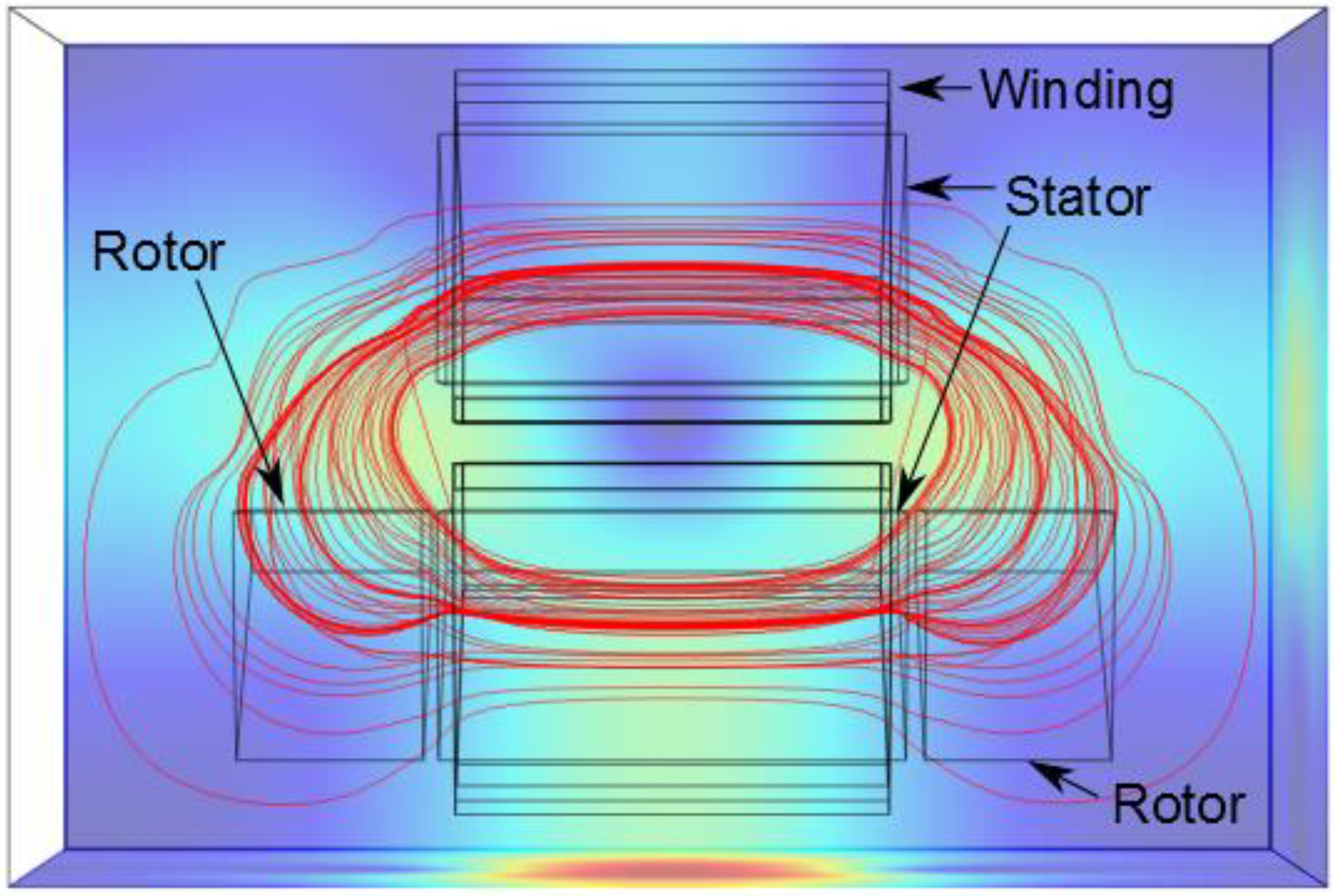
where || refers to the parallel component. The highest torque produced in an SRM is therefore developed along the component of the pole tip which is normal to the direction of rotation. This declaration is equivalent to the statement that a given magnetic flux density produces the highest attractive force when it flows between two parallel surfaces. The highest attractive force will also produce the highest energy conversion efficiency (ECE), defined by [
6] as the ratio of the tangential and normal forces:
where
Ftangent is the tangential force which creates motion,
Fnormal is the combined normal component of the radial and axial forces,
θ is the rotation angle, and
I is the phase current. The stress tensor is used to calculate the tangential and normal forces using the formula
where
is the normal vector to the backiron-air interface, and
dA is a unit of area on the integration surface. The ECE can thus be used to describe the torque density and efficiency of the design. Although two parallel surfaces would produce the highest ECE, the principle of rotary motion precludes the possibility of two parallel surfaces existing in an electric machine. The best alternative is shown in
Figure 1, two surfaces with a large parallel depth and a sufficient offset to permit motion of both poles.
Figure 1.
Best physical alternative pole configuration.
Figure 1.
Best physical alternative pole configuration.
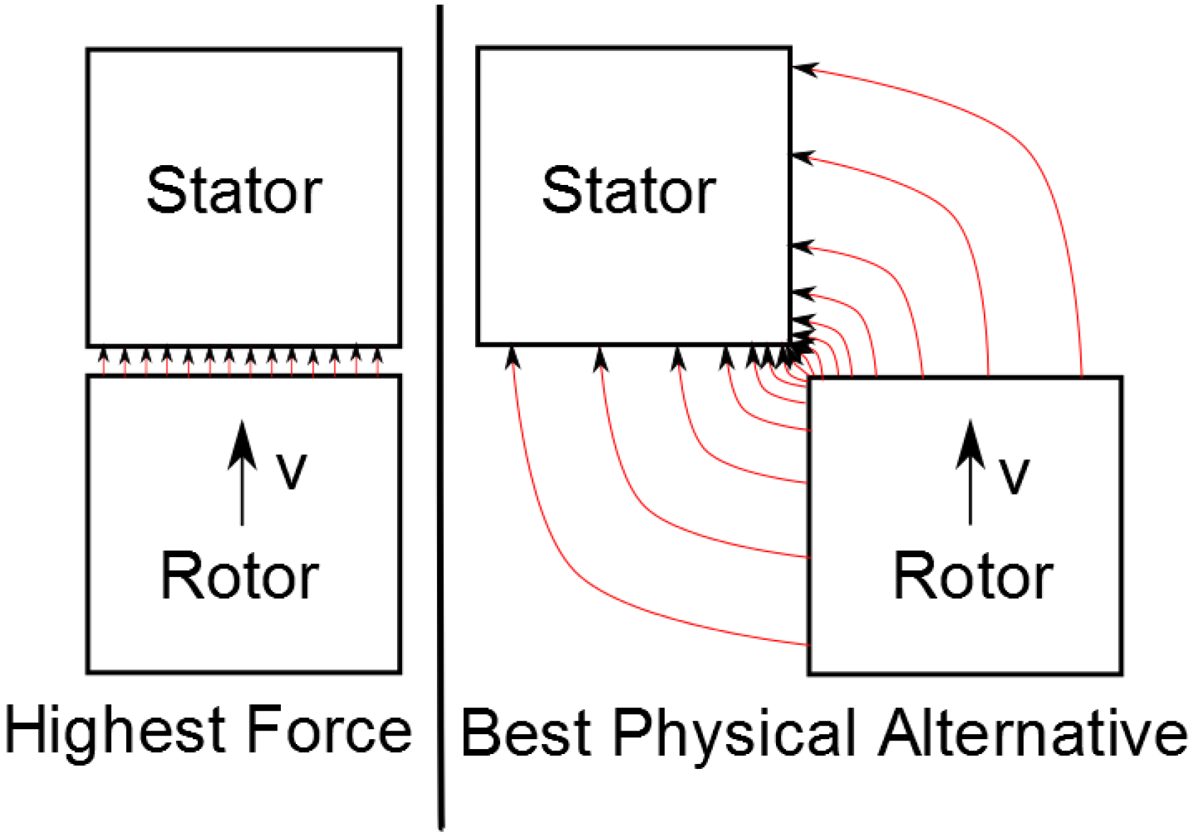
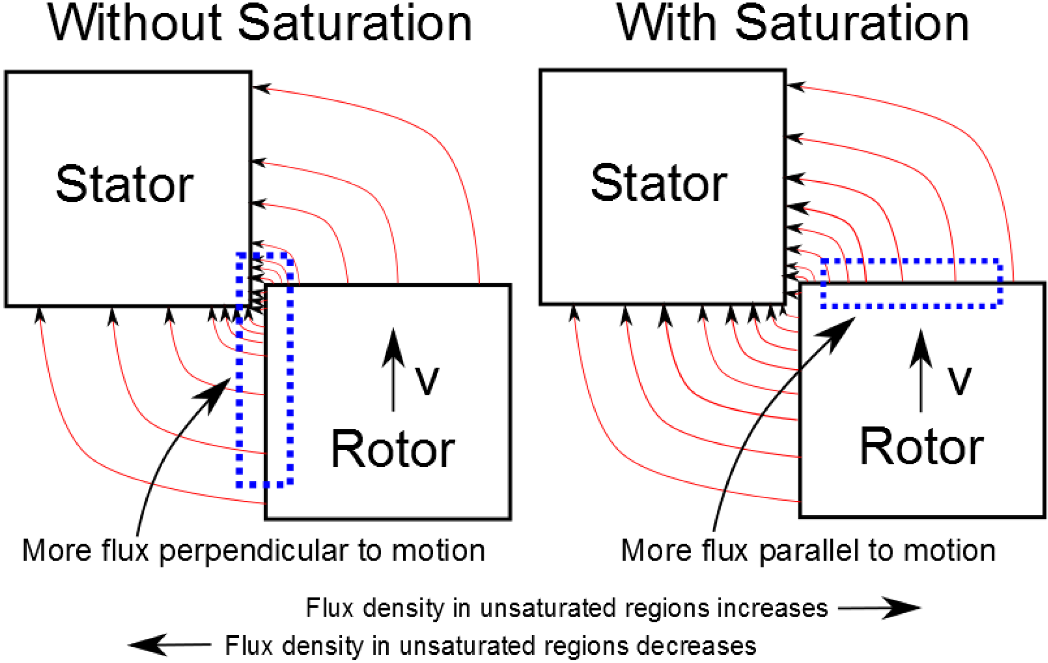
The motion of poles in an SRM is also affected by magnetic saturation. Saturation has two effects on motor performance. Saturated motors produce a smaller quantity of magnetic flux for a given phase current, but they also produce a larger quantity of torque because saturation increases the fringing flux, as in
Figure 2. There is a specific winding current which will produce the highest ECE at each rotation angle for a given nonlinear backiron material, but this current can only be calculated during the quantitative design process. In summary, the qualitative design process harnesses physical motivations to make important design decisions, but cannot be used to define the values of design parameters without the quantitative design process.
Figure 2.
Effect of saturation on flux density.
Figure 2.
Effect of saturation on flux density.
3. Design of the Motor Topology
This section presents a novel method to select SRM geometry, and defines the specific geometric parameters of SRM designs which affect the modelling process. Geometric design parameters can be described qualitatively using either empirical or physical [
18] equations. Empirical design equations are available for several standardized motors, but they are not sensitive to small design modifications, though they may include the stack length, number of poles, outer radius, and backiron saturation point. The physical approach to motor design responds to all design modifications, including pole shape, gap shape, winding geometry, driving current, and phase activation strategy, and can be used to select the design itself. We design a novel split rotor-stator in-wheel motor using the physical approach for this reason. The features of the motor are shown at the end of this section. The considerations involved in a qualitative physical design process for such a motor are as follows:
- ▪
Maximum Torque: the unaligned position should have a minimum inductance, and the aligned position should have a maximum inductance. Since inductance is dependent primarily on geometry, the unaligned position should have no overlap between rotor and stator poles, and the aligned position should correspond to complete overlap.
- ▪
Torque Shape: the shape of the torque curve can be altered by changing the pole tip shape without affecting the total quantity of torque that is produced by the motor, as long as the shape does not change the saturation behaviour of the backiron.
- ▪
Backiron Material: saturation may improve performance in machines with low ECE, but it also represents a limit on the inductance of the aligned position. The backiron should be able to carry the total flux without reaching saturation, but should saturate near the pole tip to so as to increase the fringing flux.
- ▪
Pole Size: the maximum pole size in a specific motor volume is optimal. This consideration is reinforced by a simple calculation of copper loss. The resistance of a winding is given by
where
ρc is the resistivity of copper,
lw is the length of the winding,
aw is the cross-section of the winding, and
Apole is the cross-sectional area of the pole face. The average torque for two motors with identical unaligned inductances will be a function of the magnitude of the aligned inductance. It will also be a function of the aligned field-energy
(1/2)φ2ℜ, where
φ is flux and ℜ is reluctance. Given pole areas
A2 = 2A1, with
A2 as the area of pole 2 and
A1 as the area of pole 1, equal aligned field-energies suggest that
The magneto-motive force (MMF) is given as
F = φℜ = NI, where
N is the number of turns in a coil and
I is the current in that coil. Solving for current results in
where
lflux is the path length and
μ is the permeability of the material. We see that
The resulting power requirement is
Therefore
As the area increases, power losses decrease.
- ▪
Pole Tip Shape: pole tip shaping along the tangential direction typically reduces the average torque produced by a motor, suggesting that shaping should only occur if motivated by a design requirement. Shaping along the radial and axial directions [
20] has not been investigated thoroughly to the best of our knowledge, yet it is important to consider.
- ▪
Pole Configuration: the motion of an activated pole produces the back-EMF, shapes the backiron’s magnetic hysteresis cycle, and prescribes the optimal shape of the phase current. Reducing the frequency and magnitude of hysteresis will thus increase the efficiency of the motor.
- ▪
Phase Length: a longer backiron segment per phase will both reduce the inductance of the aligned position and increase hysteresis losses. The minimum backiron length is therefore desired.
- ▪
Phase Number: a larger number of poles and phases will result in a larger average torque if the controller can achieve single-pulse control, since the ECE for the energy contained in the magnetic field is higher near the unaligned position, when there is only a small overlap between the rotor and stator poles. The size of the overlap can be reduced by increasing the number of poles. A larger number of poles will thus increase the amount of time that the active phase spends near the overlap point, producing more torque.
- ▪
Phase Alignment: a rotating machine can be either radial or axial. Machines can also be designed in the inner- and outer-rotor configurations. Displacement of the rotor and stator beyond the length of the airgap is only possible in an axial configuration, and an outer-rotor arrangement will maximize the available winding space.
Further evidence in support of the axial-flux configuration can be found in the motor geometry. The rotor-stator interface surface in a radial machine can be defined by
The rotor-stator interface surface in an axial machine can be defined by
Thus the axial configuration contains a larger interface surface for rvolume > 0.5lvolume , assuming a radial rotor-stator interface radius of 0.5rvolume.
The design considerations above can be used to develop a set of motors with different numbers of rotor and stator poles. The set of motors includes five unique features:
- (1)
The first feature, a short flux path, is implemented using a simple phase configuration, shown in
Figure 3. Flux passes sequentially through each pole, where a machine with a long flux path has flux that passes through poles on opposite sides of the stator.
- (2)
The second feature, an axial-flux motor configuration, is implemented by arranging the rotor and stator in an axial sequence, where a radial-flux machine is arranged such that the rotor is co-radial with the stator.
- (3)
The third feature, an outer-rotor topology, is implemented by placing sets of rotor poles on either side of the set of stator poles. This produces an inner-stator, outer-rotor topology.
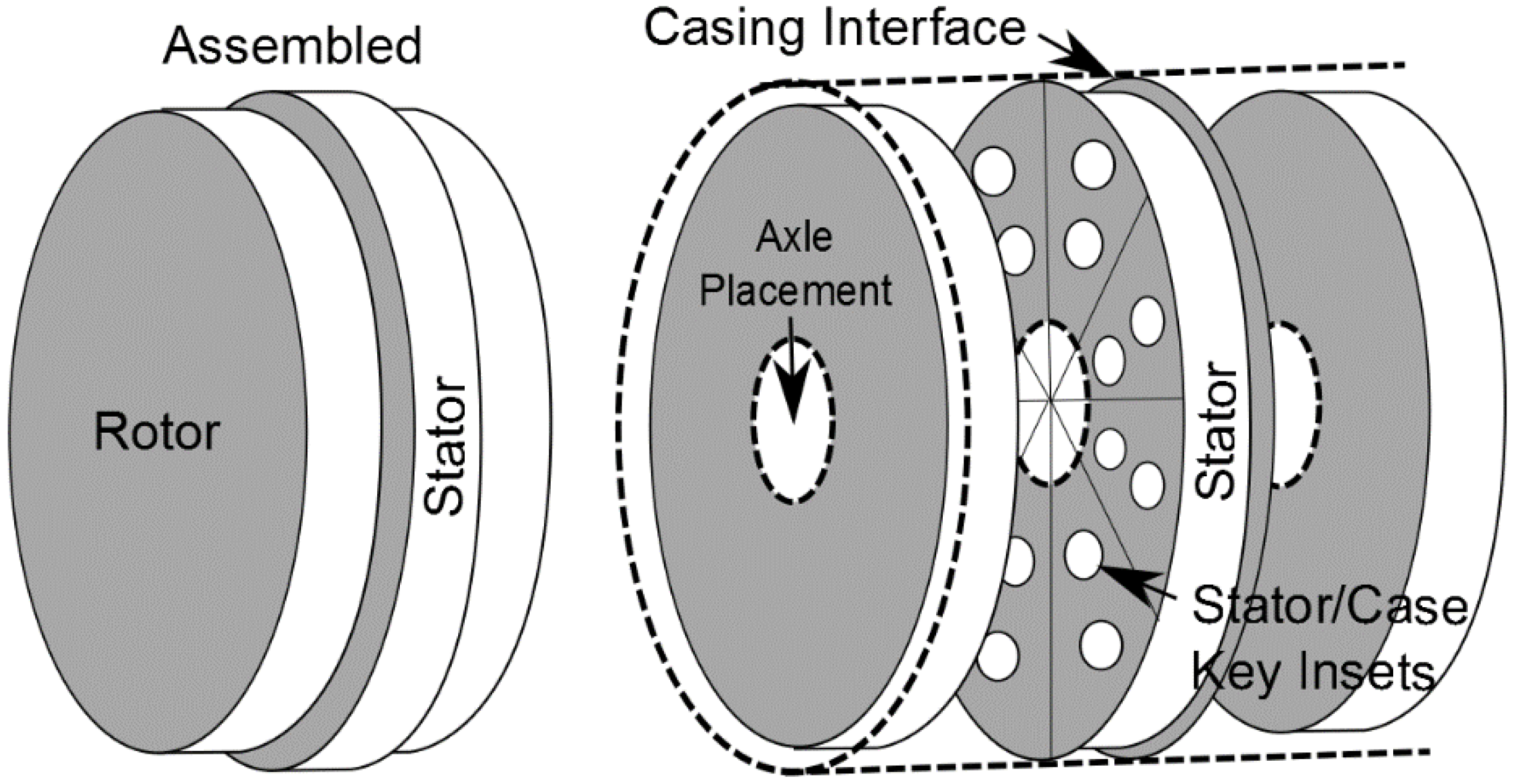
- (4)
The fourth feature, a split rotor-stator coupling, is implemented by permitting the rotor to move vertically with respect to the stator, as shown in
Figure 4. The motion is restricted such that at least some overlap between a rotor pole and a stator pole is maintained in the aligned position.
- (5)
The fifth feature, wherein no flux reversal occurs in the stator, is implemented using a new phase activation strategy, described in
Table 1. This strategy avoids flux reversal in the stator during sequential pole activation cycles, but it does not completely avoid flux reversal in the rotor. The first rotor activation cycle causes flux to flow in one direction through the first set of rotor poles, where the second activation cycle causes flux to flow in that same direction through the alternate set of rotor poles. The flux which flows through first set of rotor poles is then reversed the next time that the first set of rotor poles is activated. Given that the first set of rotor poles is inactive during the second activation cycle, some degree of magnetization will dissipate, but some amount of hysteresis will occur nonetheless.
Figure 3.
An example of a flux pattern in a single phase of an AFSRM.
Figure 3.
An example of a flux pattern in a single phase of an AFSRM.
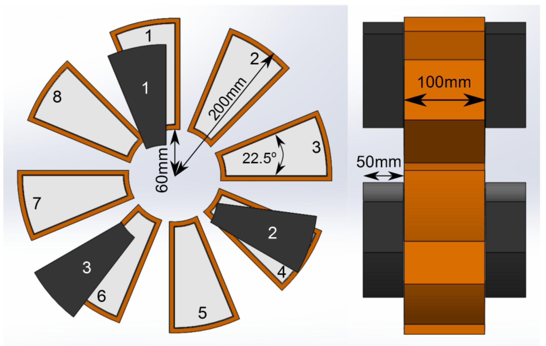
Figure 4.
An example of the phase configuration and pole numbering in an 8/3 AFSRM, prior to optimization.
Figure 4.
An example of the phase configuration and pole numbering in an 8/3 AFSRM, prior to optimization.
Table 1.
Stator pole activation strategy in an 8/3 AFSRM.
Table 1.
Stator pole activation strategy in an 8/3 AFSRM.
| Rotor Angle | 1 | 2 | 3 | 4 | 5 | 6 | 7 | 8 |
|---|
| 0°–15° | x | x | | | | x | x | |
| 15°–30° | x | x | | x | x | | | |
| 30°–45° | | | | x | x | | x | x |
| 45°–60° | | x | x | | | | x | x |
| 60°–75° | | x | x | | x | x | | |
| 75°–90° | x | | | | x | x | | x |
| 90°–105° | x | | x | x | | | | x |
| 105°–120° | | | x | x | | x | x | |
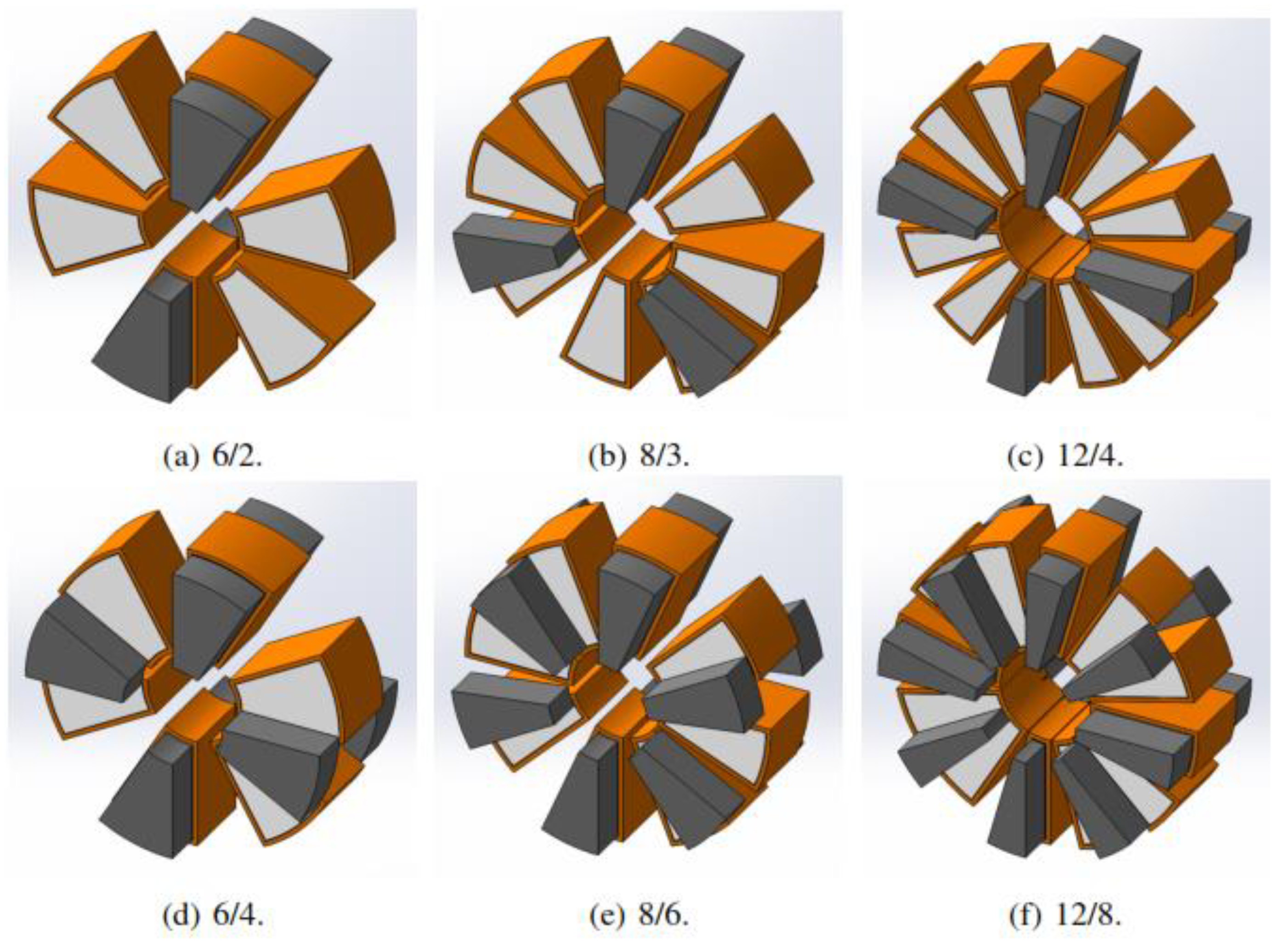
These features, as listed above, differentiate the machines in
Figure 5 from motors which are available in the literature. The new machines do not appear fundamentally different from simple AFSRMs, but modifications to their sizing permit unique utilization of the backiron with a new activation strategy. Traditional motors in the literature do not permit vertical motion between the rotor and stator, though there are some works which discuss control of such machines [
19]. Traditional motors also utilize a ‘yoke’ which connects the rotor poles, and permits flux to flow from one pole to the next. Finally, machines with no flux reversal do exist in the radial configuration [
11], but these devices occupy larger volumes than their counterparts which do have flux reversal. A machine with the features listed above occupies a smaller volume than a comparable axial-flux device, due to the lack of a yoke, and does not have flux reversal in the stator. Thus, a novel split rotor-stator in-wheel motor is selected from the set of machines with these features. The parameters of the machine proposed in this section will be determined in the next section, using a motor model and an optimization process.
Figure 5.
A set of examples of the AFSRM motor topology.
Figure 5.
A set of examples of the AFSRM motor topology.
4. Modelling of an Axial-Flux SRM in 3D
This section presents a model that accurately describes the geometric and electromagnetic characteristics of the AFSRM topology, highlighting the effect of motor geometry on the energy conversion process through direct computation of the airgap reluctance. Verification of model accuracy is achieved using FEA [
21], though a full electrical model and control system is needed to evaluate dynamic behaviour [
22].
We propose a closed-form linear model that is dependent on important motor parameters, including the shape of the rotor-stator interface surface. The linear model is valid for the purpose of optimization so long as single-parameter variations yield monotonic changes in the performance index. Nonlinearities that arise due to magnetic saturation are assumed to be monotonic. The linear model is based on an integral inductance function, similar to the integral permeance function [
23]. The inductance function is in turn based on the reluctance:
where
l is the length of the flux path,
μ is the permeability of that path, and
A is its effective cross-sectional area. The inductance of the same path can be calculated by
where
N is the number of turns in the winding producing the MMF. Then the inductance of one small flux path traced from source to sink can be given by
where
dx and
dy represent infinitely-small orthogonal vectors on the pole tip surface. The inductance is therefore represented by
The geometry of the flux path is conveniently lumped into the path length
l, such that this technique can be applied in 2D or 3D. Maxwell’s equations provide convenient boundary conditions for the integral which produce elliptic flux paths that traverse material surfaces at 90° angles. Ramanujan [
24] developed a good approximation of the path length along the ellipse:
where
ai is the semi-major axis,
bi is the semi-minor axis, and
i indicates the region on the pole surface, where the semi-major and semi-minor axes may vary between regions. The path length in the airgap between two surfaces can be calculated as a fraction of the total elliptic path,
where
φ is the angle between both surfaces. The inductance function may then be integrated numerically.
The inductance calculations are divided into aligned and unaligned configurations, and the unaligned configuration is further divided into four integrable path groups. Both configurations are broken into backiron and airgap segments. Finally, region division is achieved using a ratio of the leakage and backiron reluctances, and integration is performed over the stator pole surface.
The inductance is the sum of the regular and leakage inductances:
with the regular inductance given by
and the leakage aligned inductance given by
The average torque is then
Where
Ns and
Nr are the number of poles on the stator and rotor, while
ΔW = Waligned - Wunaligned. The energy differential
ΔW is directly dependent on the number of windings in each pole, and on the reluctance of the motor as it moves from the minimum to maximum position. This model is therefore static, and does not account for the rotational speed of the motor. A transient model which does account for the rotational speed of the motor is the subject of the following subsection.
4.1. Discretization of Motor Geometry for Transient Simulation using Analytic Circuit Models
A dynamic model of transient AFSRM behaviour is derived from the time-invariant equivalent circuit by applying a rule-based filter to a discretized version of the motor geometry.
The equivalent circuit is produced using the integral inductance function, but it ignores the backiron due to the much larger permeability of the airgap. Such simplification permits the model to emphasize the effect of vertical rotor displacement on reluctance during simultaneous rotation and displacement. The dynamic model is implemented using a MATLAB code which evaluates the geometry of the motor, breaking the model into a discrete grid, based on the overlap between rotor and stator poles.
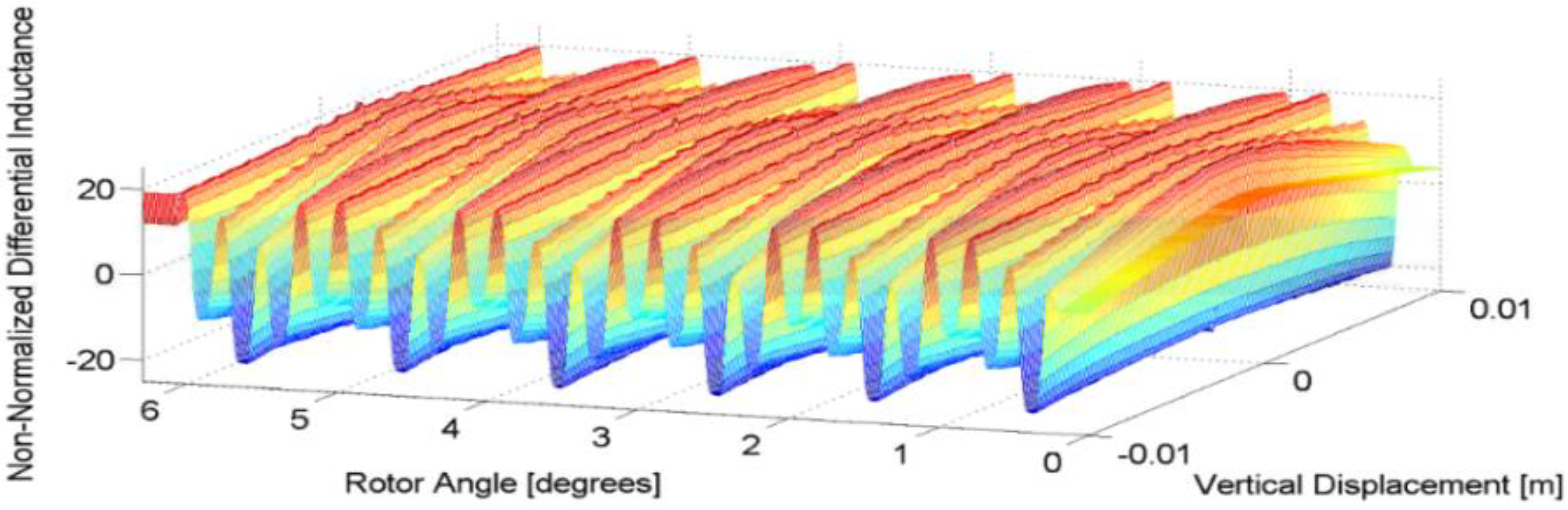
As subdivided by the grid lines, each unit of area will be termed a grid unit. One flux path from each grid unit is traced from the surface of each active stator pole, through the airgap, the rotor pole, the next stator pole, and back to the original stator pole. When the reluctance of the flux paths, the total quantity of flux, and the torque have been calculated, the rotor is rotated through the arc of one grid unit, and the process is restarted. When the rotor has been rotated through one complete revolution, the vertical location of the rotor is incremented along an upward radial vector. To establish the effect of vertical displacement on reluctance, flux, and torque, the vertical location is incremented, and the rotor is rotated, until every viable configuration has been investigated. The differential inductance is then calculated using the reluctance and flux from the dynamic model. An example of the differential inductance for an 8/6 machine is shown in
Figure 6. Note that the profile shown has not been normalized by the winding number, or any other motor parameter, so it is many times higher than the standard value of the inductance. The normalized differential inductance will be dependent on the value of the magnetomotive force and the permeability of the core material.
Figure 6.
Differential inductance calculated using the dynamic AFSRM model.
Figure 6.
Differential inductance calculated using the dynamic AFSRM model.
4.2. Determination of the Model Parameters
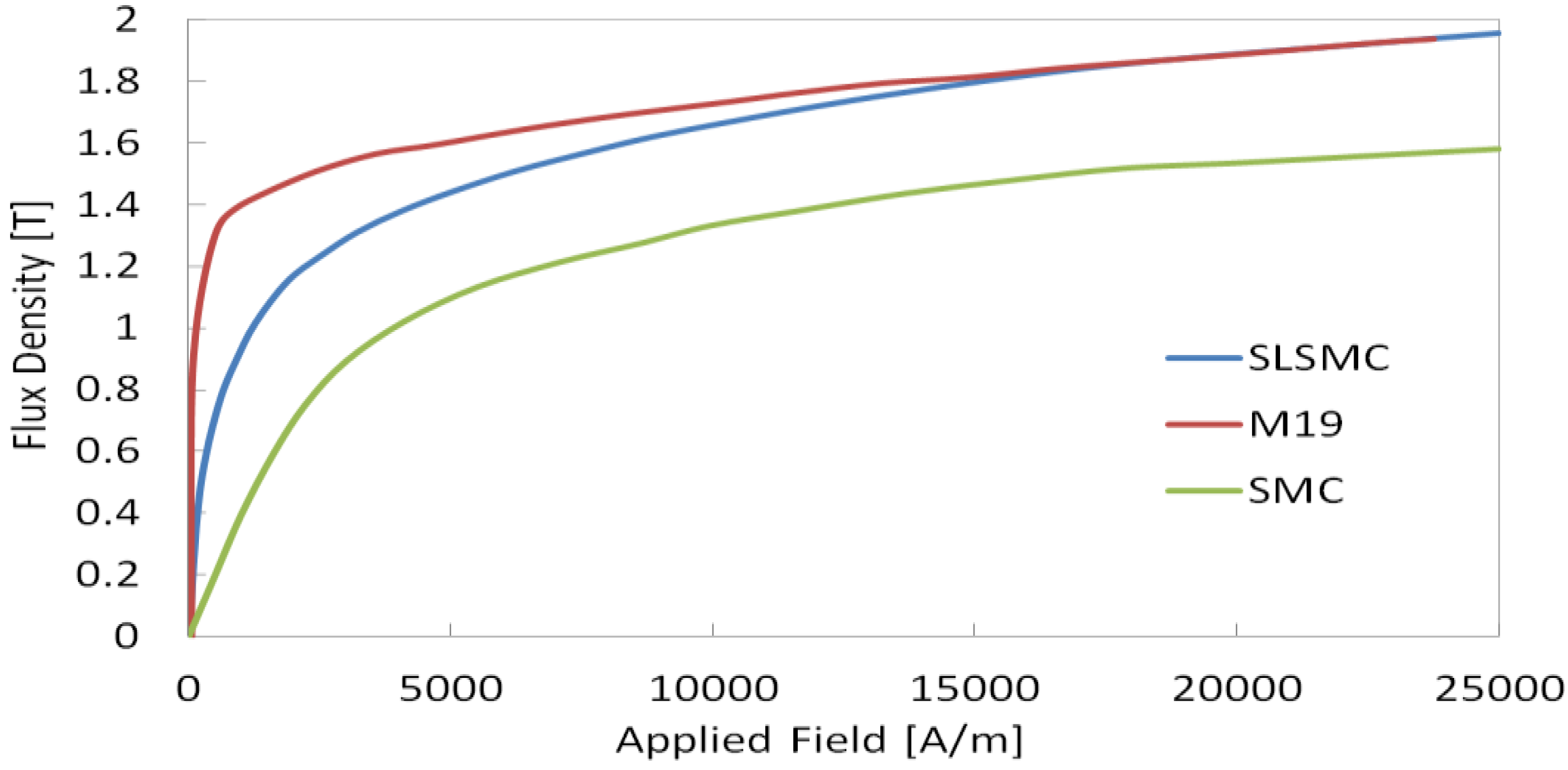
The other parts of the modelling process, including the magnetic saturation behaviour shown in
Figure 7, the hysteresis loss calculation developed by [
9], the lamination implementation in
Figure 8, and the AC loss calculation developed by [
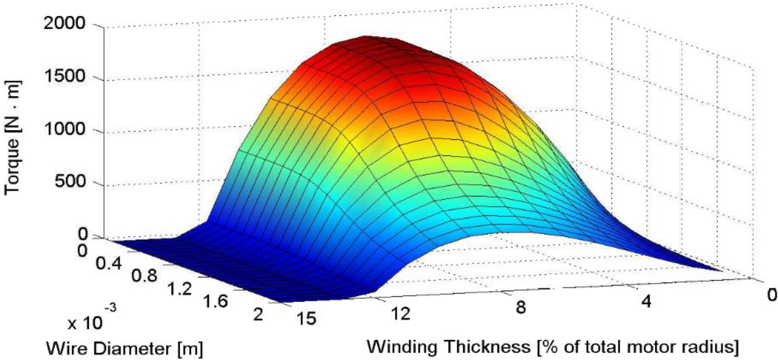
25], have also been completed. The optimization process has been performed using a modified Taguchi method which produces the profile shown in
Figure 9. The modified Taguchi method uses the principles of sensitivity and orthogonal arrays to reduce the number of motor parameters that are considered in the optimization, which would otherwise be too numerous for most computational approaches [
26]. Apart from the independent parameters shown in
Figure 9 all other motor dimensions have either been formulated as dependent parameters, eliminated from the optimization by the modified Taguchi method, or have been determined by the geometric constraints of an in-wheel application. The resulting optimized parameters are shown in
Table 2.
Figure 7.
Magnetic saturation behavior of the flux density with different core materials [
10]. The sintered lamellar soft magnetic composite (SLSMC) can carry a high flux density, but at low applied field an SLSMC component will have worse performance than a comparable laminated component.
Figure 7.
Magnetic saturation behavior of the flux density with different core materials [
10]. The sintered lamellar soft magnetic composite (SLSMC) can carry a high flux density, but at low applied field an SLSMC component will have worse performance than a comparable laminated component.
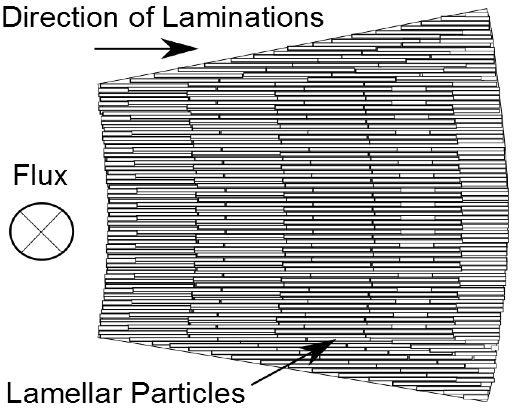
Figure 8.
Lamellar particle orientation in an SLSMC. Segmented lamellar metal chips are used instead of rolled steel sheets, permitting a pressing operation in place of traditional machining.
Figure 8.
Lamellar particle orientation in an SLSMC. Segmented lamellar metal chips are used instead of rolled steel sheets, permitting a pressing operation in place of traditional machining.
Figure 9.
Motor torque optimization surface as a function of winding dimensions. Smaller wires permit more turns per pole, increasing the MMF and the torque. As the winding thickness increases, more copper can be added to the motor, but less backiron is available to conduct magnetic flux.
Figure 9.
Motor torque optimization surface as a function of winding dimensions. Smaller wires permit more turns per pole, increasing the MMF and the torque. As the winding thickness increases, more copper can be added to the motor, but less backiron is available to conduct magnetic flux.
Table 2.
Optimized AFSRM parameters.
Table 2.
Optimized AFSRM parameters.
| Parameter | Value |
|---|
| Peak Torque, below 15 [rad/s] | 2500 [Nm] |
| Peak Torque, below 15 [rad/s] | 500 [Nm] |
| Continuous Torque | 200 [Nm] |
| Peak Torque/Phase | 1194.8 [Nm] |
| Voltage | 500 [V] |
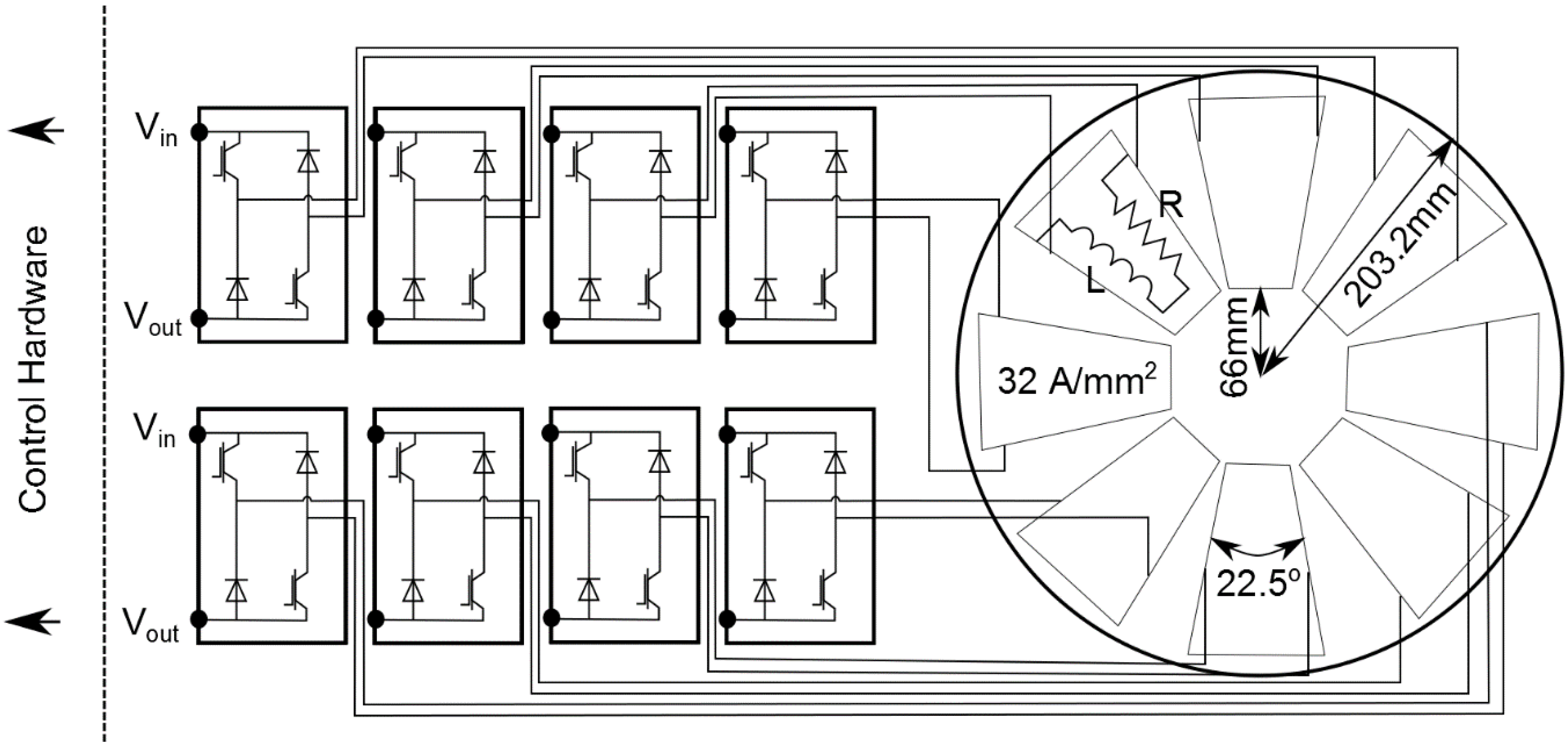
| Current Density | 32 [A/mm2] |
| Fill Factor | 0.8 |
| Weight | 40 [kg] |
| Outer Radius | 203.2 [mm] |
| Inner Radius | 66 [mm] |
| Length of Airgap | 1 [mm] |
| Winding Thickness | 15 [mm] |
| Stator Width | 50 [mm] |
| Rotor Width | 21.4 [mm] |
It is important to note that the hysteresis loss model and the copper loss model used in the optimization process will not be used to calculate the efficiency of the motor because the consistency of the assumptions between efficiency calculations in this paper and in the literature is unknown. The BH curve in
Figure 7 is sufficient to indicate the increased torque density which is possible in a machine using an SLSMC instead of a powder metal backiron.
This section has finalized the geometric component of the motor design process, but in order to establish the suitability of the AFSRM topology for in-wheel applications, the cooling requirement should be investigated. Therefore, a thermal analysis method is proposed in the following section.
5. Thermal Analysis of the AFSRM
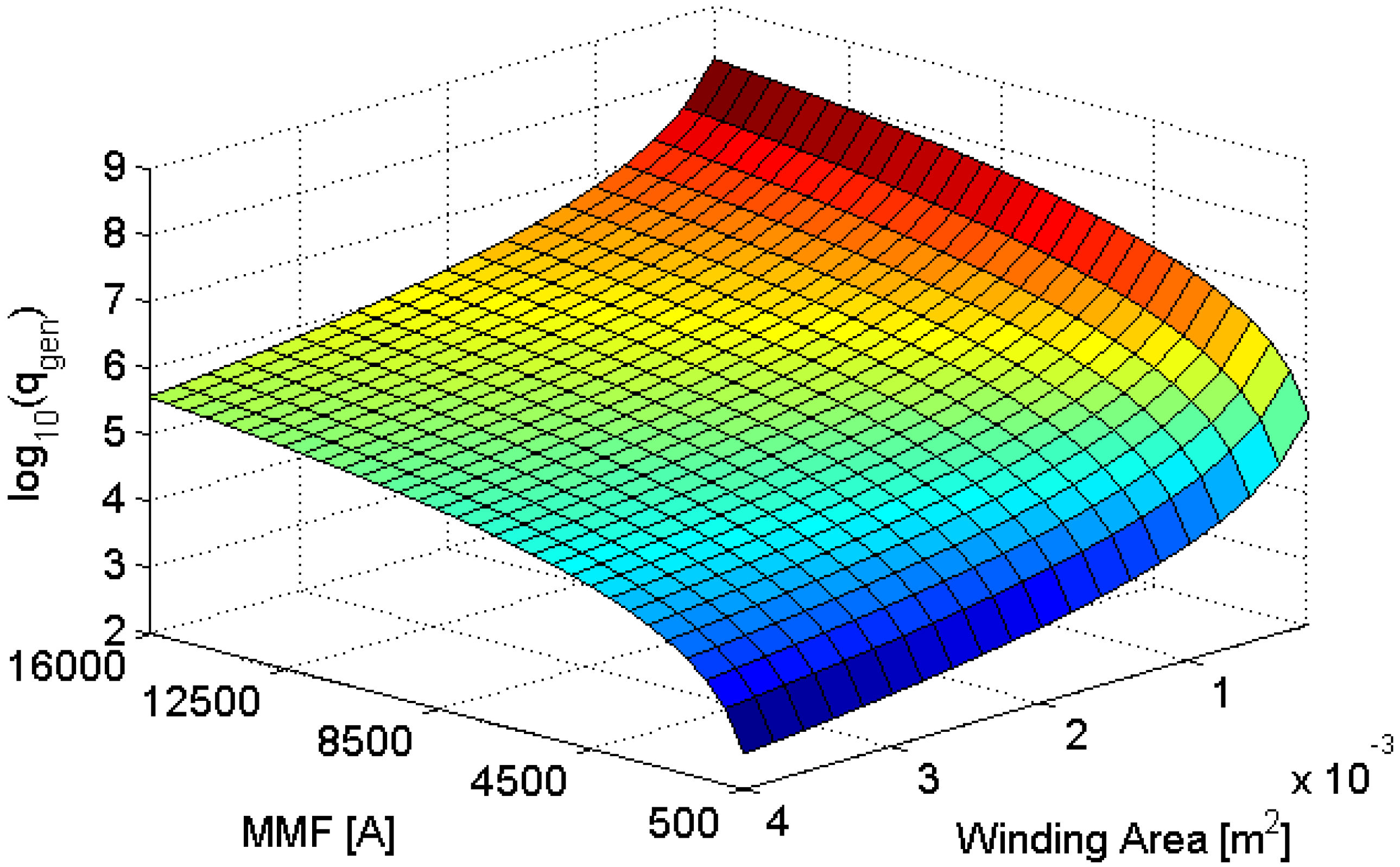
This section investigates the cooling requirements of the new AFSRM topology using a combination of thermal equivalent circuits and FEA. To aid in the design process, a normalized heat input to the thermal model is developed.
The heat input to the thermal model of an axial-flux motor can be normalized using the magnetomotive force (MMF). This normalization will permit the results of further computational analyses to apply to a range of designs with fixed MMFs (
F). Several motors with the same MMF can then be considered identical for purposes of thermal analysis. Thus, normalization permits the design process to focus on the flux density, rather than on specific design parameters. Since several designs with identical MMFs can now be considered identical, fewer iterations of numerical calculations are now required during the design process. Solving for the current required to produce a specific MMF,
where
N is the number of wires in the winding. The input heat density is then
Where
P is the thermal power,
I is the current in the wire,
ρ is the resistivity of the wire,
A is the cross-sectional area of the wire,
d is the diameter of the wire,
R is the resistance of the winding,
lw is the depth of the winding,
υ is the volume of the winding,
rw is the radial thickness of the winding, and
Aw is the total cross-sectional area of the winding. The heat generation per unit of volume as a function of winding cross-sectional area and MMF is then given by
Figure 10.
A thermal model which uses the normalized heat input may be developed using linear equivalent circuits. The parameters of the thermal model are shown in
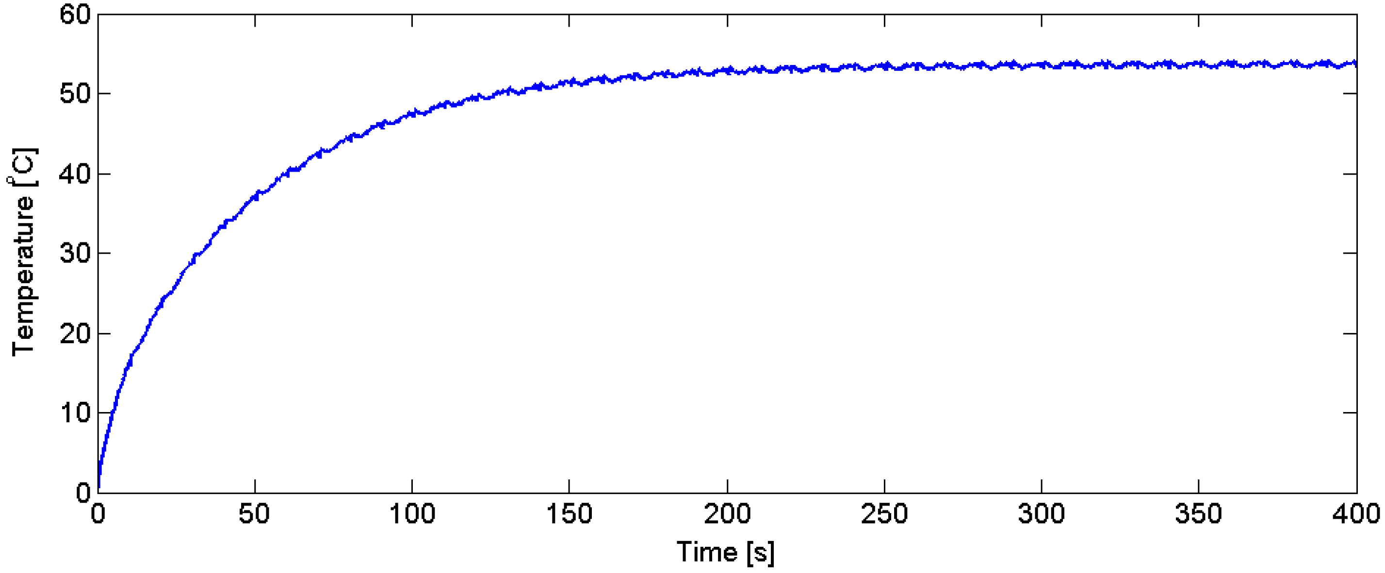
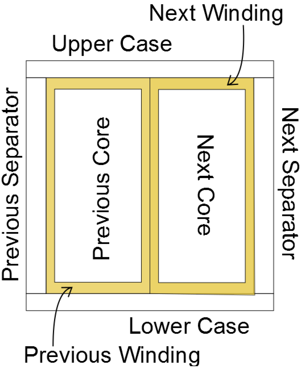
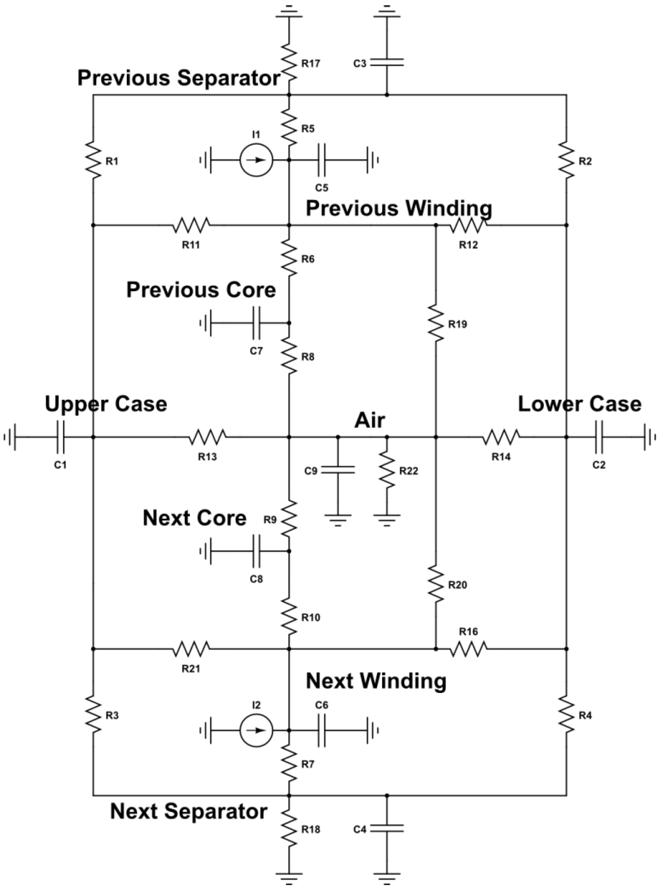
Table 3. A nodal structure is established which describes the location of each subcomponent of the motor. Nodes are connected by thermal resistances which represent conduction. Each node also contains a capacitive element which represents the heat capacity of that subcomponent. Additional elements may be added to account for convection or radiation. The AFSRM model is symmetric about two axes, permitting a subsection of the full motor to represent the complete machine. A half-segment of one phase, shown in
Figure 11, with structural material, is therefore modelled. The resulting thermal circuit is depicted in
Figure 12, and the transient thermal behaviour of the motor during continuous operation is shown in
Figure 13.
Figure 10.
Normalized heat generation in an axial-flux motor.
Figure 10.
Normalized heat generation in an axial-flux motor.
Table 3.
Parameters of the thermal model.
Table 3.
Parameters of the thermal model.
| | Density | Specific Heat Capacity | Thermal Conductivity |
|---|
| | ρ [kg/m3] | cp [J/kg°C] | k [W/m°C] |
|---|
| Backiron | 7700 | 490 | 25 |
| Casing | 7850 | 450 | 52 |
| Windings | 8950 | 380 | 360 |
| Epoxy Resin | 1400 | 1700 | 0.5 |
| Separators | (7850 + 1400)/2 | (450 + 1700)/2 | (52 + 0.5)/2 |
| Air | 1.177 | 1005 | 0.0267 |
Figure 11.
Geometry of th AFSRM used for the transient thermal model.
Figure 11.
Geometry of th AFSRM used for the transient thermal model.
Using the normalized model inputs, we can also produce a set of standardized data for a variety of designs using FEA. This FEA process can be performed in either two dimensions (2D) or three dimensions (3D). Although many works [
27] have used 2D FEA in the past, it is problematic to use 2D FEA for axial-flux motors because they rotate in a plane which is normal to the direction of flux flow. Linearized representations of axial-flux motors have been proposed in some cases [
27] to circumvent this problem, but linearization can affect the location of the hotspots in the motor. For this reason, we will use 3D FEA in this paper. 3D FEA will provide precise knowledge of both average temperature and hotspot temperature [
28], and will be used to identify the locations in which cooling systems are needed.
Figure 12.
Thermal circuit of the AFSRM.
Figure 12.
Thermal circuit of the AFSRM.
Figure 13.
Transient temperature of the AFSRM winding calculated using a thermal equivalent circuit.
Figure 13.
Transient temperature of the AFSRM winding calculated using a thermal equivalent circuit.
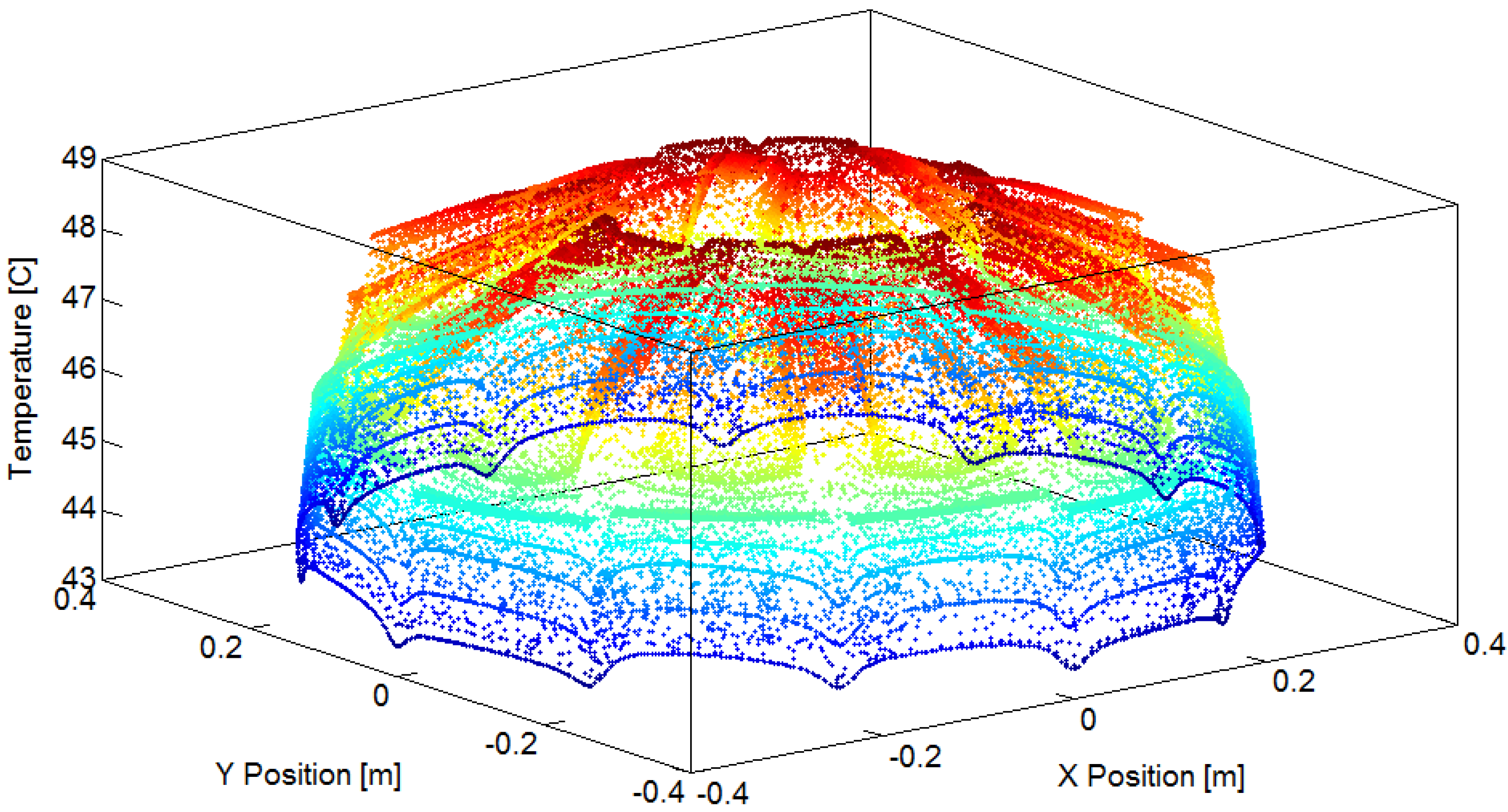
Here, we implement a 3D FEA model of the motor within a cylindrical region, which is designated to be ‘air’. Boundary conditions are applied on each surface of the region, or on the internal volume of the region, depending on the formulation of the condition. The winding elements are represented by segmented regions, and within each region, an appropriate current density is applied. Finally, a tetrahedral FEA mesh is specified which has a minimum resolution equal to or smaller than the size of the smallest air gap. The resulting thermal distribution is shown in
Figure 14. The predicted temperature is lower than the operating temperature of many permanent-magnet machines, which can have coil temperatures above 100 °C [
29].
Figure 14.
Maximum temperature in the AFSRM.
Figure 14.
Maximum temperature in the AFSRM.
This section has documented a thermal analysis method for the new AFSRM topology, but before the performance of the AFSRM can be investigated, a control method must be implemented. Since the AFSRM includes the new design features developed in
Section 3, methods in the literature [
19] would be difficult to adapt without extensive modifications. Thus, a new AFSRM control method will be the subject of the following section.
9. Conclusions
In this paper, we developed a new AFSRM topology using physics-based insights from electromagnetic motor models. The features of the topology include a short flux path, an axial-flux, outer-rotor configuration, a split rotor-stator coupling, and no flux reversal in the stator. The fundamental improvement over a standard AFSRM is a larger backiron flux path with a lower reluctance per turn in the winding. A comprehensive model of the new topology was created using a hybrid modelling technique which involved MECs, Maxwell’s stress tensor, and FEA. The new modelling technique is different from existing techniques in two important ways; first, an integral inductance calculation is used instead of a traditional inductance calculation or a permeance calculation [
23], and second, the transient motor behaviours are modelled using a numerical code based on the integral inductance function, instead of FEA [
33]. These differences make the new modelling technique more accurate, and easier to apply to different configurations of this motor topology. An 8/6 AFSRM was chosen as an example of the new topology, using a fuzzy controller to calculate optimal switching angles, an SLSMC backiron, and a distributed inverter. The torque density, ECE, and efficiency of the 8/6 AFSRM were calculated using a simulation model with lookup tables from FEA implemented in Simulink.
In comparison to other SRM topologies intended for in-wheel applications [
13,
32], simulations indicate that the new AFSRM has a higher torque density by mass, and a comparable torque density by volume, although the thermal performance in continuous operation has yet to be evaluated. Furthermore, FEA calculations show that the new topology has a higher ECE than other comparable motors [
6], and a similar efficiency [
33], even with a larger airgap. This indicates that the topology is suited for low speed, high torque applications. Thus, the new AFSRM topology could be used in an in-wheel direct-drive electric vehicle, or in another application that requires a combination of high torque and high durability. Future work can be focused on improved optimization processes including transient analysis, a nonlinear adaptation of the integral inductance function, and a better control design.


