Article

Multi-Error Collaborative Tooth Surface Modification of High Reduction Ratio Hypoid Gears Considering Cutter and Machine Tool Errors


School of Mechanical Engineering, University of Shanghai for Science and Technology, Shanghai 200093, China
*
Author to whom correspondence should be addressed.
Machines 2026, 14(7), 792; https://doi.org/10.3390/machines14070792
Submission received: 29 May 2026 / Revised: 5 July 2026 / Accepted: 12 July 2026 / Published: 13 July 2026
(This article belongs to the Section Advanced Manufacturing)

Abstract

In the machining process of high reduction ratio hypoid gears (HRHGs), cutter tool geometry errors (CGE) and machine tool setting parameters errors (MSE) significantly affect tooth surface accuracy. Existing studies mainly focus on analyzing the effects of MSE alone or investigate CGE and MSE under conventional reduction ratios, while comprehensive research on the coupled effects of tooth top error (TTE), tooth root error (TRE), and root mean square deviation (RMS) is limited. To address this gap, this paper proposes a tooth surface correction method based on the integration of Sobol’ sensitivity analysis and NSGA-II optimization algorithms. A multidimensional mapping model was established between CGE, MSE parameters, and tooth surface accuracy indices (TTE, TRE, and RMS) to achieve coordinated error optimization. Sobol’ global sensitivity analysis (GSA) was conducted to identify the key influencing parameters of cutter geometry and machine settings. A multi-objective optimization model was developed using the NSGA-II algorithm, targeting TTE, TRE, and RMS. The fast non-dominated sorting mechanism effectively identified the Pareto-optimal solutions, enabling inverse compensation of critical error factors and significantly improving the machining accuracy of hypoid gears. The results revealed that, on the concave flank, the deviations of tooth top, tooth root, and tooth mean square decreased by a minimum improvement of 75.4%, 70.1%, and 73.3%. Furthermore, on the convex flank, the corresponding deviations decreased by a minimum improvement of 78.1%, 75.0%, and 73.1%. These results verify the high accuracy of the proposed algorithm in correcting the tooth flanks of HRHGs.

1. Introduction

In the manufacturing of high reduction ratio hypoid gears, factors such as machining errors, elastic deformation, and thermal effects can cause deviations between the actual and designed tooth surfaces, thereby impairing the transmission performance of the gear pair. To improve tooth surface accuracy, coordinate measuring machines (CMM) are commonly employed to capture the spatial coordinates of discrete points on the actual surface. Based on these measurements, an error correction model is developed, and machining parameters are adjusted to compensate for the deviations. This approach is widely regarded as an effective means of enhancing the manufacturing precision of gear pairs. In recent years, considerable research has been conducted on tooth surface error compensation [1,2,3,4,5].
Su et al. [6] established a tooth surface error model suitable for CNC machining and achieved the minimization and CNC correction of tooth surface errors by optimizing the setting parameters of the cradle machine tool. On this basis, Wang et al. [7] constructed a comprehensive analysis model including axial, tangential and radial tool setting errors to quantitatively evaluate the influence of different setting errors on gear geometric accuracy. Subsequently, Li et al. [8] proposed a digital inverse correction method based on one-dimensional probe measurement data to improve the tooth surface geometric accuracy and transmission quality of hypoid gears and minimize the tooth surface geometric deviation. For circular arc bevel gears, Scholars [9,10] proposed a compensation method based on the correction of key machining parameters to address the problem of easy accumulation of tooth surface errors during machining. By analyzing the influence of multiple machining parameters on tooth surface deviation, the main parameters were selected for optimization and adjustment. Furthermore, Chen et al. [11] established a direct mapping relationship between the machine tool motion axis and tooth surface geometric error, realizing real-time dynamic compensation during machining and effectively reducing tooth surface deviation.
To accurately identify error sources and their coupling effects, sensitivity analysis has gradually become an essential tool in tooth surface optimization. In this study, a global sensitivity analysis (GSA) approach is employed, which utilizes a global sampling strategy to evaluate the independent effects of input parameters and their higher-order nonlinear interactions, making it well-suited for error analysis in complex nonlinear systems [12]. Among various GSA techniques, the Sobol’ variance decomposition method [13,14] is widely adopted, as it quantifies the influence of each input parameter on the output variable by calculating its variance contribution, thereby revealing coupling relationships among parameters. For instance, Li et al. [15] applied the Sobol’ method to analyze the sensitivity and coupling effects of geometric errors in horizontal machining centers. Han et al. [16] combined an improved Sobol’ method with a quasi-Monte Carlo algorithm to conduct a comprehensive sensitivity analysis of 38 geometric error components in a dual-lead double-head grinding machine, elucidating the mechanism of error propagation. Building upon the Sobol’ GSA framework, Scholars [17,18,19,20] further considered the magnitude and randomness of geometric errors, introduced specific indexing angles of the rotary axis, identified the key geometric errors of five-axis machine tools, and evaluated error components and coupling effects under different indexing angles, thereby providing a theoretical basis for error compensation. In terms of tooth surface error compensation, this paper uses the NSGA-II algorithm [21] through fast non-dominated sorting and crowding distance mechanism to achieve convergence while maintaining the diversity of the solution set and efficiently identify the Pareto optimal solution; it has strong adaptability to the high-dimensional, nonlinear, non-convex and complex constraint problems solved in this paper and can coordinate and optimize multiple error indicators at the same time. Existing research mainly focuses on conventional reduction ratio bevel gears, focusing on analyzing the influence of machine tool setting parameter error (MSE) on tooth surface accuracy. However, cutter tool geometry error (CGE) [22,23] also has a significant impact on gear tooth surface accuracy. Therefore, it is urgent to conduct a systematic study that comprehensively considers the effects of CGE and MSE on tooth surface deviation (TTE, TRE, and RMS) in high reduction ratio hypoid gears.
Based on the above research background, this study focuses on tooth surface correction of HRHGs and conducts three main tasks:
(1)
Develop a precise mathematical model of HRHGs, incorporating CGE and MSE to provide a theoretical basis for subsequent error analysis and optimization;
(2)
Systematically investigate the effects of CGE and MSE on TTE, TRE and RMS and identify key error sources using Sobol’ analysis;
(3)
Construct a multi-objective optimization model integrating CGE and MSE and propose a standard NSGA-II-based method to achieve coordinated enhancement of tooth surface accuracy.

2. Tooth Surface Modeling Method for Pinion of High Reduction Ratio Hypoid Gears

The Hypoid Gears with Format and Tilt method (HFT) is commonly employed for the machining of high reduction ratio hypoid gears. In this method, the gear is typically fabricated using the forming process, while the pinion tooth surface is generated through the tilt method. Based on the face-milling principle, this study integrates spatial coordinate transformation and gear meshing theory to establish both the theoretical tooth surface model and the error tooth surface model for the pinion. The error model systematically accounts for the influence of machine tool setting parameter errors and cutter geometry errors on tooth surface accuracy.

2.1. Theoretical Tooth Surface Modeling of High Reduction Ratio Hypoid Gears

Gleason Corporation is a global leader in the manufacturing of spiral bevel gear machining equipment. Figure 1 presents the main structural components of the Gleason No. 116 gear milling machine. During the actual machining process, the cutter position is adjusted through the coordinated control of Q , β , J and I x , which can be equivalently represented by parameters i 1 , j 1 , S r 1 and q 1 . The workpiece position is determined by X M 1 , E 1 , X 1 and X B 1 . The relative kinematic relationship between the cutter and the workpiece is governed by the sliding base denoted as X B 1 , which ensures accurate gear tooth generation.
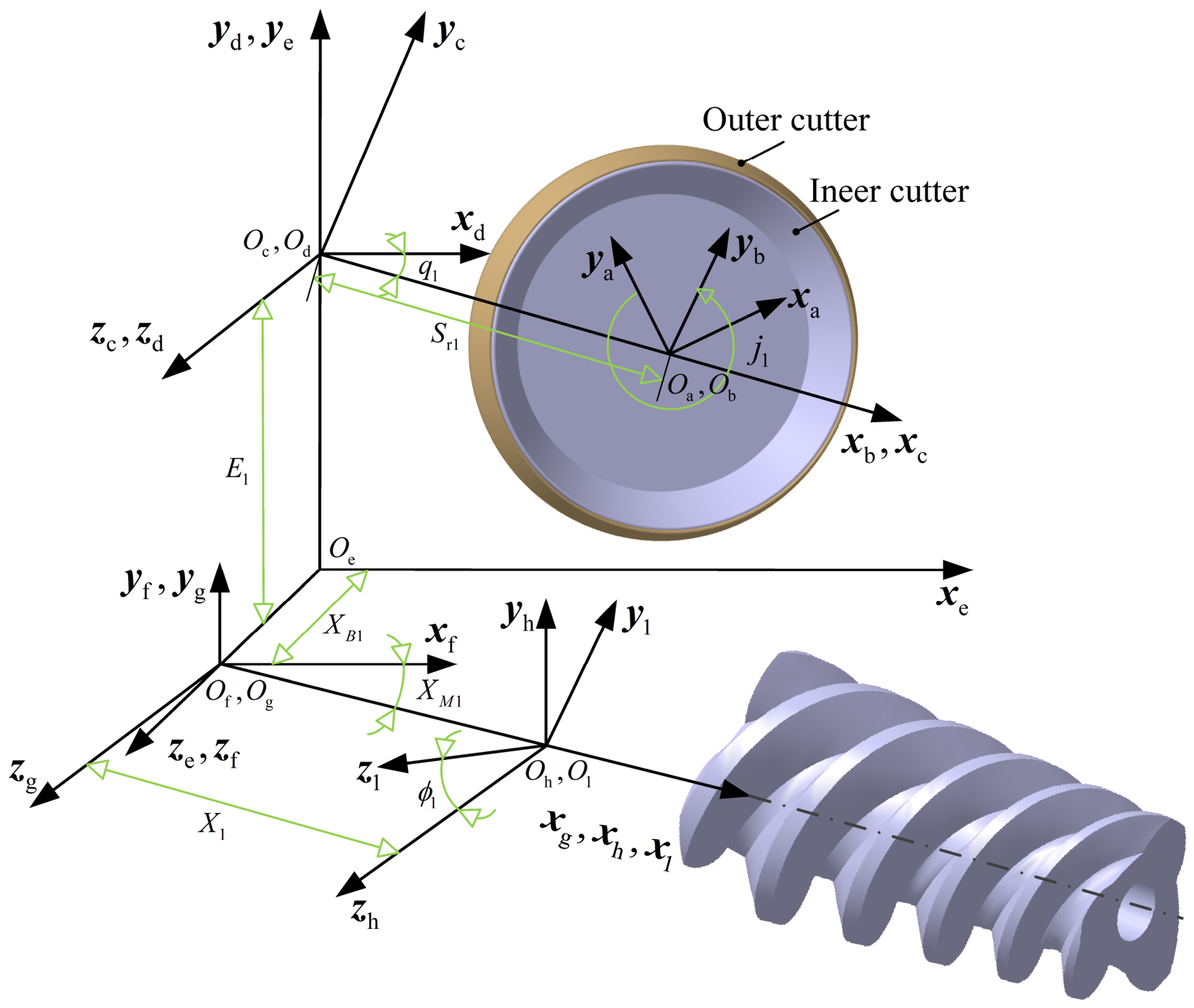
Taking the machining process of the pinion in a high reduction ratio hypoid gear as the research object (with the concave surface machining as an example), Figure 2 illustrates the geometric configuration of the cutter used for machining the concave surface. Figure 3 shows the coordinate systems involved in the machining process: coordinate system S p represents the tool body coordinate system rigidly connected to the cutter head; coordinate system S e denotes the global reference coordinate system of the machine tool; coordinate systems S c and S 1 are fixed, respectively, to the cradle and the pinion. The remaining coordinate systems serve as auxiliary references to comprehensively describe the relative spatial motion between the cutter and pinion.
The mathematical model of the tooth surface of the pinion machined by the HFT method is derived as follows:
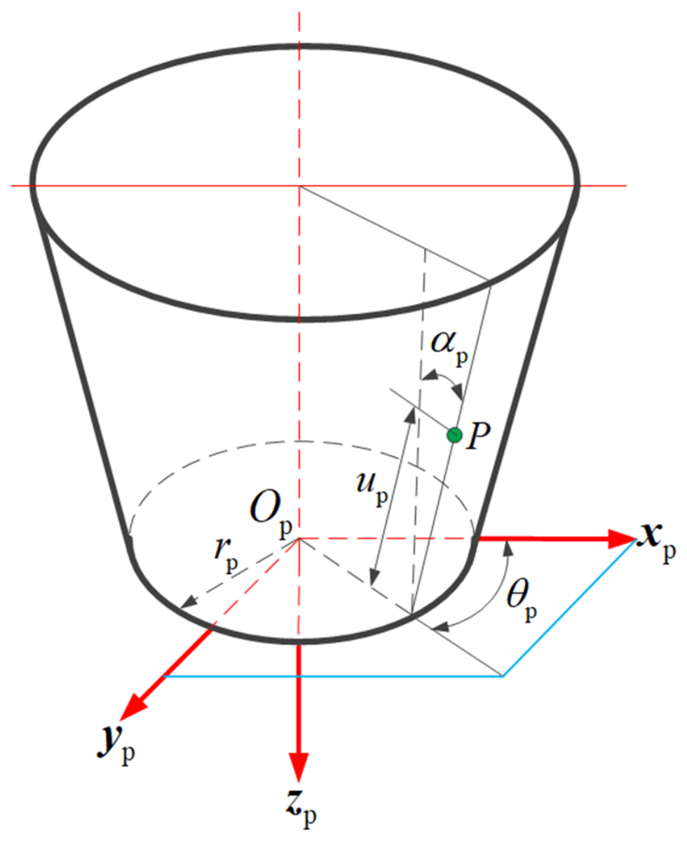
First, the radial vector r p and the corresponding unit normal vector n p at an arbitrary point P on the cutter surface of the pinion are constructed. Based on Figure 2, these vectors are expressed in the relevant coordinate systems S p as follows:
r p ( u p , θ p ) = ( r p + u p sin α p ) cos θ p ( r p + u p sin α p ) sin θ p u p cos α p 1
n p = cos α p cos θ p cos α p sin θ p sin α p
Then, the equation of the cutter’s cone surface, initially defined in the tool coordinate system, is transformed into the pinion coordinate system to establish the mathematical model of the pinion tooth surface. The radial vector r 1 and unit normal vector n 1 of the tooth surface corresponding to point P on the pinion in the coordinate system S 1 is:
r 1 ( u p , θ p , ϕ 1 ) = M 1 p r p ( u p , θ p ) n 1 ( u p , θ p , ϕ 1 ) = L 1 p n p ( u p , θ p )
M 1 p = 1 0 0 X 1 0 cos ϕ 1 sin ϕ 1 0 0 sin ϕ 1 cos ϕ 1 0 0 0 0 1 cos X M 1 0 sin X M 1 X B 1 sin X M 1 0 1 0 E 1 sin X M 1 0 cos X M 1 X B 1 cos X M 1 0 0 0 1 cos ( q 1 + i 01 ϕ 1 ) sin ( q 1 + i 01 ϕ 1 ) 0 0 sin ( q 1 + i 01 ϕ 1 ) cos ( q 1 + i 01 ϕ 1 ) 0 0 0 0 1 0 0 0 0 1 sin ( j 1 ) cos ( j 1 ) 0 S r 1 cos ( j 1 ) sin ( j 1 ) 0 0 0 0 1 0 0 0 0 1 cos ( i 1 ) 0 sin ( i 1 ) 0 0 1 0 0 sin ( i 1 ) 0 cos ( i 1 ) 0 0 0 0 1
L 1 p = M 1 p ( 1 : 3 , 1 : 3 )
Finally, the theoretical tooth surface is solved by combining the meshing equation between the pinion tooth surface and its generating wheel.
n p c 1 v p c 1 = 0
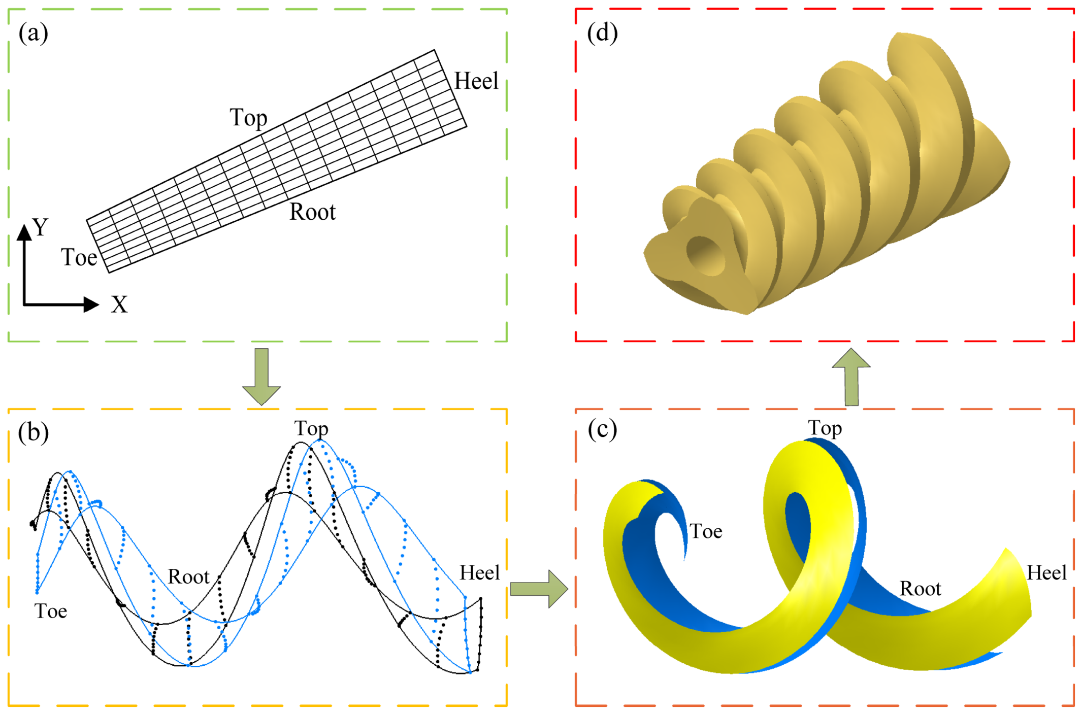
To ensure the accuracy of the model, a 9 × 17 point cloud was selected to represent the pinion tooth surface. The specific modeling process is illustrated in Figure 4. First, the tooth surface is projected onto a rotational projection plane, followed by mesh division on the projected surface. Then, the corresponding point cloud coordinates are calculated using the aforementioned numerical method. Based on the obtained point cloud, the tooth surface is reconstructed and the complete 3D model of the pinion is subsequently generated.

2.2. Error Tooth Surface Modeling of High Reduction Ratio Hypoid Gears Considering CGE and MSE

During the actual machining process, the accuracy of the tooth surface is influenced not only by errors of the machine tool setting parameters (MSE) from their nominal design values but also by cutting tool geometric errors (CGE). This study focuses specifically on two types of CGE: tool radius error and tooth profile angle error. These errors alter the meshing relationship between the cutter and the pinion, thereby affecting the final tooth surface geometry. The combined effects of MSE and CGE lead to discrepancies between the as-machined tooth surface and the theoretical design surface. Therefore, a comprehensive error model that incorporates both CGE and MSE can effectively characterize the distribution of tooth surface errors during the machining process, providing a more accurate representation of the differences between the machined and theoretical tooth surfaces and offering a solid theoretical foundation for subsequent error compensation and optimization.
The cutting tool geometric errors (CGE) equation can be expressed as:
r p e ( u p , θ p ) = ( r p + Δ r p + u p sin ( α p + Δ α p ) ) cos θ p ( r p + Δ r p + u p sin ( α p + Δ α p ) ) sin θ p u p cos ( α p + Δ α p ) 1
The machine tool setting parameters error can be denoted as Δ ξ l ( Δ X M 1 , Δ E 1 , Δ X 1 , Δ X B 1 , Δ i 1 , Δ j 1 , Δ S r 1 , Δ q 1 , Δ i 01 ) ; the machine tool setting parameters errors (MSE) equation is formulated as:
X M 1 e = X M 1 + Δ X M 1 , E 1 e = E 1 + Δ E 1 , X 1 e = X 1 + Δ X 1 X B 1 e = X B 1 + Δ X B 1 , i 1 e = i 1 + Δ i 1 , j 1 e = j 1 + Δ j 1 S r 1 e = S r 1 + Δ S r 1 , q 1 e = q 1 + Δ q 1 , i 01 e = i 01 + Δ i 01
The normal error between the error tooth surface and the theoretical tooth surface discrete point can be expressed as:
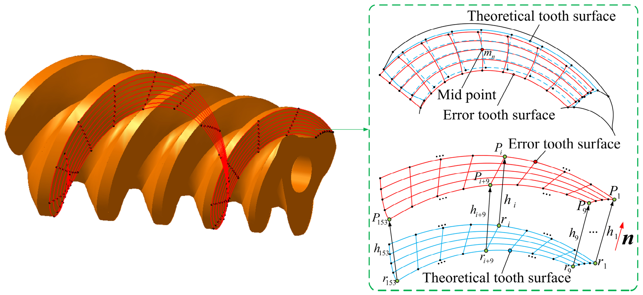
( P i r ( ( u p , θ p , ϕ 1 ) i , ξ l ) )   ·   n ( ( u p , θ p , ϕ 1 ) i , ξ l ) = h i
This study considers the tooth top errors (TTE) f T T E and tooth root errors (TRE) f T R E in the tooth shape error, expressed as:
f T T E = h 1 + h 145
f T R E = h 9 + h 153
The root mean square (RMS) f R M S of the tooth surface error is denoted as:
f R M S = 1 N i = 1 N h i 2
where i represents the i -th sampling point and n ( ( u p , θ p , ϕ 1 ) i , ξ l ) denotes the radial and normal vectors corresponding to the theoretical surface discrete point at the sampling point, as shown in Figure 5.

2.3. Numerical Example

Table 1 gives the basic geometric parameters of the pinion of the HRHGs. Based on the HFT method, the corresponding cutter parameters and machine tool setting parameters can be obtained. The specific values are shown in Table 2.

3. Global Sensitivity Analysis (GSA) of CGE and MSE on Tooth Surface Errors Based on Sobol’ Method

3.1. Global Sensitivity Analysis (GSA) Based on the Sobol’ Method

To improve the tooth surface accuracy of high reduction ratio hypoid gears during actual machining, it is essential to optimize both the cutter tool geometry parameters (CGE) and machine tool setting parameters (MSE). This study introduces the Sobol’ Global Sensitivity Analysis (GSA) method based on variance decomposition to quantitatively evaluate the effects of CGE and MSE on tooth surface deviations, thereby providing a theoretical basis for parameter optimization.
The Sobol’ method decomposes the total variance of the model output into contributions from individual input parameters and their interactions, making it well-suited for nonlinear and high-dimensional complex systems. Specifically, the model output function can be expressed as:
Y = f ( ξ l ) = f ( ξ 1 , ξ 2 , , ξ p )
Among them, Y is the model output, and ξ 1 to ξ p are input parameters. The model function is further expanded into multiple sub-functions superimposed [22]:
f ( ξ l ) = f 0 + i = 1 p f i ( ξ i ) + i < j f i j ( ξ i , ξ j ) + + f 1 , 2 , , p ( ξ 1 , ξ 2 , , ξ p )
where f 0 is equal to the output, f i ( ξ i ) is the independent contribution of the individual changes, f i j ( ξ i , ξ j ) is the alternating effect of the individual changes, and the subsequent high-frequency interaction.
The total variance of the model output V ( Y ) is defined as [24]:
V ( Y ) = i = 1 p V i + i < j V i j + + V 1 , 2 , , p
where V i is the variance contributed by the individual parameter ξ i and V i j represents the variance contribution from interactions between parameters.
Due to the model’s nonlinear nature, analytical integration is infeasible; therefore, the Monte Carlo method is employed to estimate the variance by random sampling within the reasonable parameter ranges based on their normal distributions:
V ^ = 1 N k = 1 N f ( ξ ( k ) ) f 0 2
To improve computational accuracy, the Sobol’ method utilizes two independent N × p sample matrices and calculates partial variances as follows:
V ^ i = 1 N 1 k = 1 N f ( ξ a ( k ) ) f ( ξ b ( k ) , ξ a , i ( k ) ) f 0 2 V ^ i = 1 N 1 k = 1 N f ( ξ b ( k ) ) f ( ξ b ( k ) , ξ a , i ( k ) ) f 0 2
where V ^ i denotes the variance caused by the i -th parameter, and V ^ i represents the variance caused by all parameters except the i -th.
Based on these, the sensitivity indices are defined as:
First-order sensitivity index:
S i = V ^ i V ^
Total effect sensitivity index:
S T i = 1 V ^ i V ^
Higher-order sensitivity index and this paper only considers the higher-order interaction contribution:
S ( i ) = S T i S i
These sensitivity indicators can identify the cutter tool geometry parameters and machine tool setting parameters that have a significant impact on the tooth surface error, thus laying the foundation for subsequent parameter optimization and improving machining accuracy.

3.2. Global Sensitivity Analysis (GSA) of CGE and MSE on Tooth Surface RMS, TTE and TRE

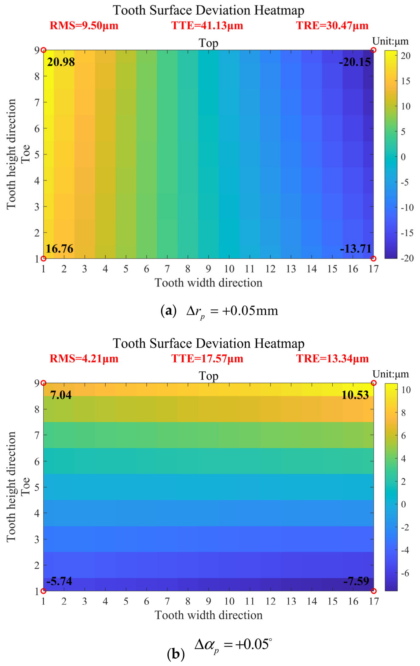
Figure 6a,b illustrate the influence of cutter geometry errors (CGE) on the root mean square deviation (RMS), total tooth error (TTE), and tooth root error (TRE) of the tooth surface during the machining of high reduction ratio hypoid gears. The results indicate that deviations in the cutter radius have a significant impact on all error metrics, with RMS, TTE, and TRE reaching 9.50, 41.13, and 30.47 μm, respectively. The corresponding heatmaps reveal that such deviations can cause substantial disturbances in the spiral angle of the tooth surface, which may seriously impair meshing performance. In contrast, errors in the cutter’s profile angle have a relatively minor effect on RMS, TTE, and TRE, and their influence on the pressure angle of the tooth surface is also limited and localized.
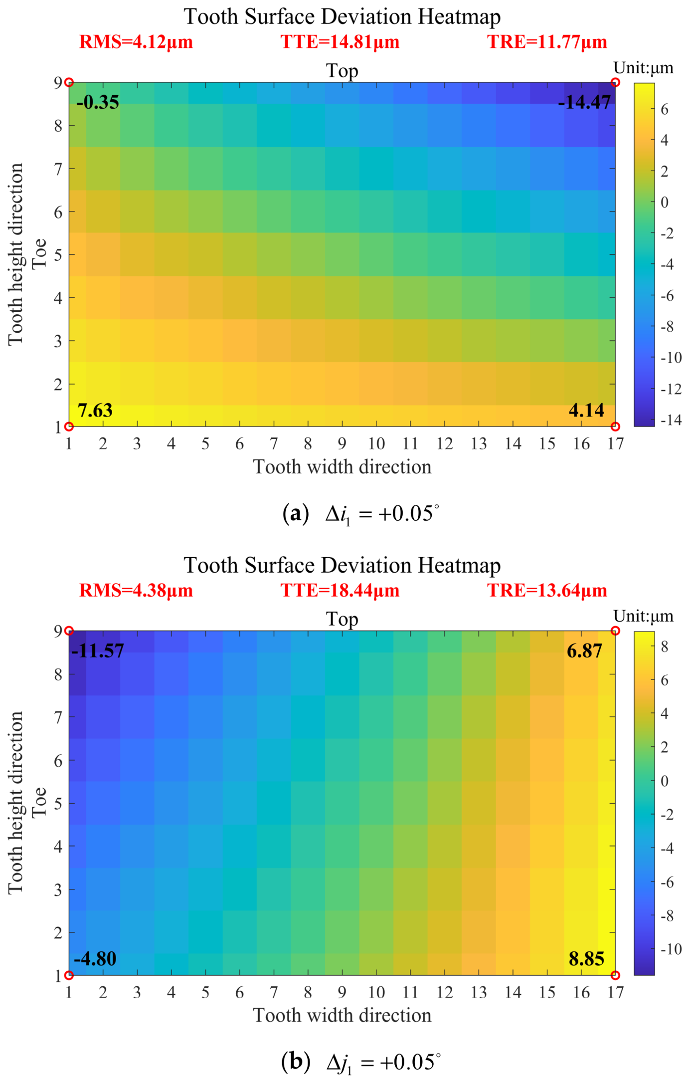
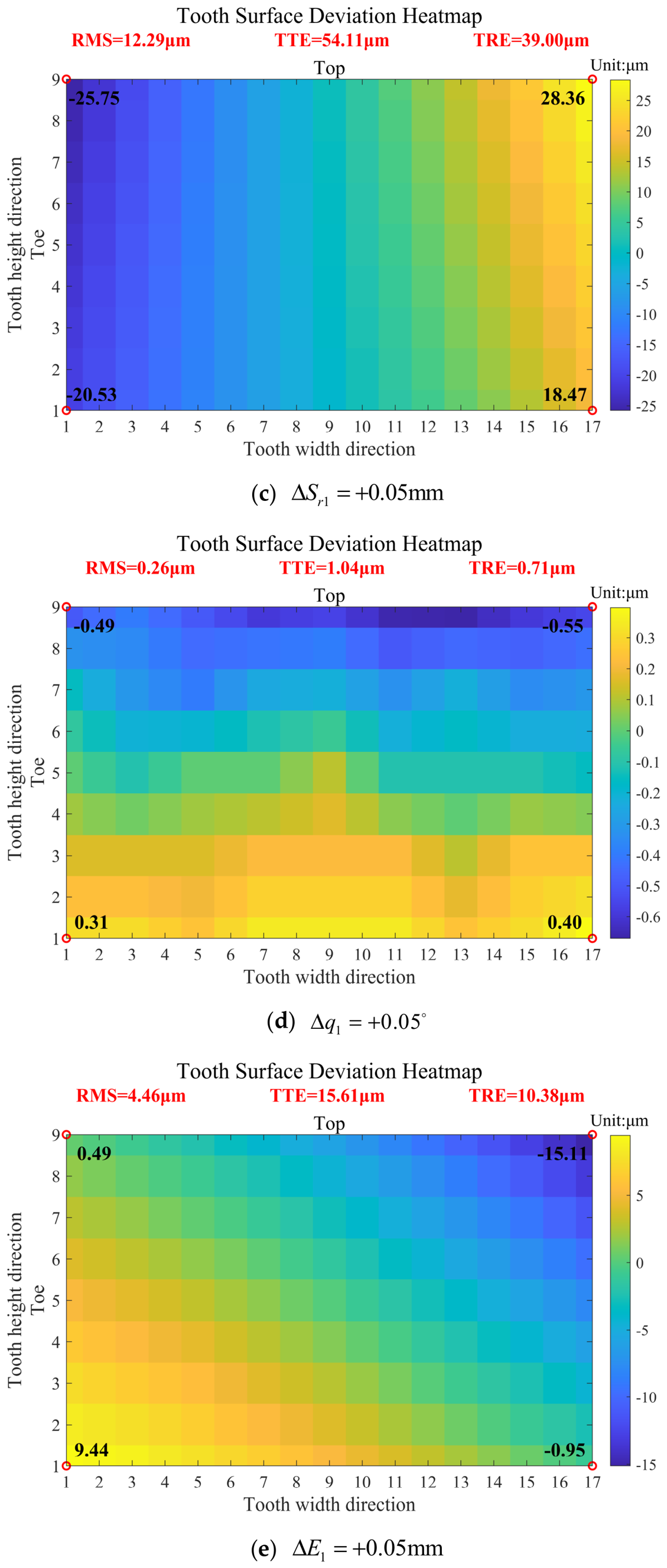
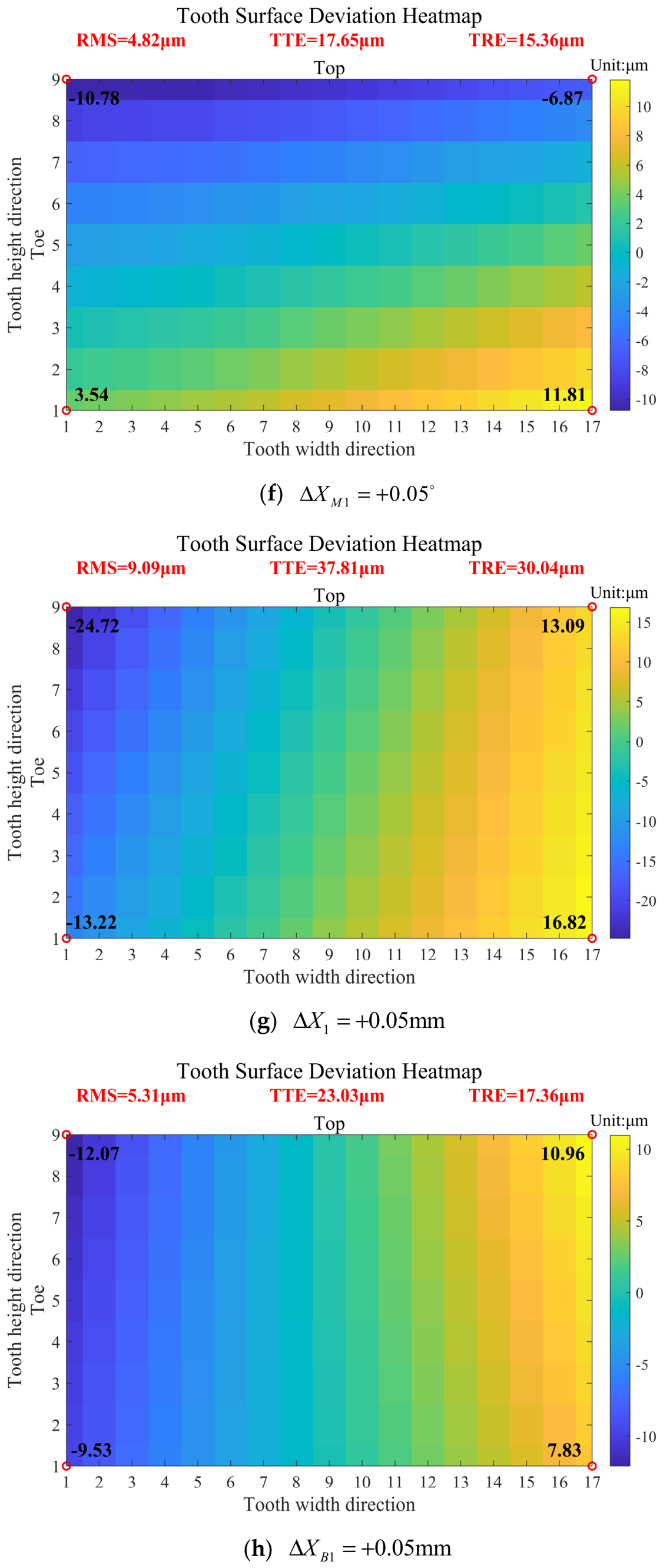
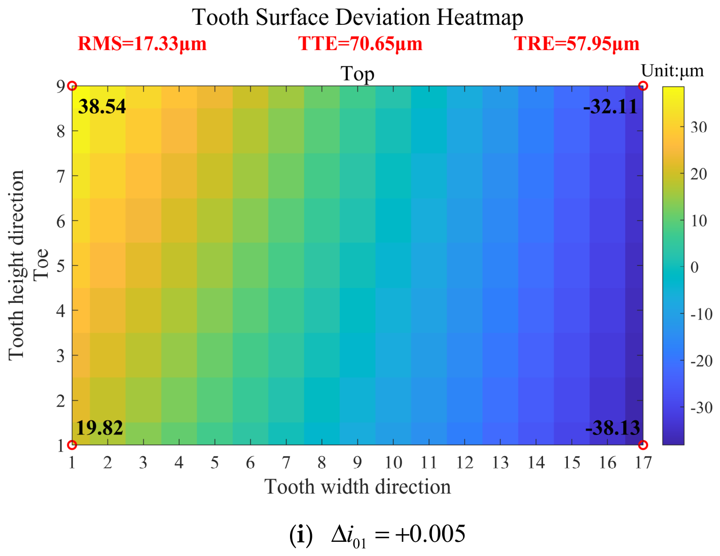
Figure 7a–i illustrate the influence of various machine setup parameter errors (MSE) on tooth surface error metrics, including root mean square deviation (RMS), total tooth error (TTE), and tooth root error (TRE), during the machining of high reduction ratio hypoid gears. The results indicate that the roll ratio i 01 , radial distance S r 1 , and machine center to back X 1 have the most significant impact on these error metrics, while the effects of tilt angle i 1 , swivel angle j 1 , blank offset E 1 , machine root angle X M 1 , and sliding base X B 1 are comparatively minor. The influence of center roll position q 1 is found to be negligible. As shown in the corresponding heatmaps, deviations in the i 01 and S r 1 notably affect the spiral angle across the entire working tooth surface. Specifically, the S r 1 determines the spatial location of the cutting blade during machining, and any variation in this position leads directly to changes in the spiral curvature of the tooth surface. The i 01 defined as the number of revolutions the pinion makes per full rotation of the cutter about the cradle is particularly sensitive; even slight deviations can cause significant alterations in the tooth surface spiral pattern and result in large-scale form errors. Moreover, small changes in the X 1 can shift the entry and exit points of the blade, leading to substantial diagonal deviations across the tooth surface. It is also noteworthy that the q 1 has the least effect on RMS, TTE and TRE. This is because its influence on the tooth surface is transmitted through a long and complex error propagation path, during which its effect is significantly attenuated. This observation is consistent with practical machining experience and supports the validity of the sensitivity analysis.
In order to more intuitively and accurately reflect the impact of CGE and MSE on RMS, TTE and TRE, the error values shown in Table 3 are assigned to CGE and MSE.
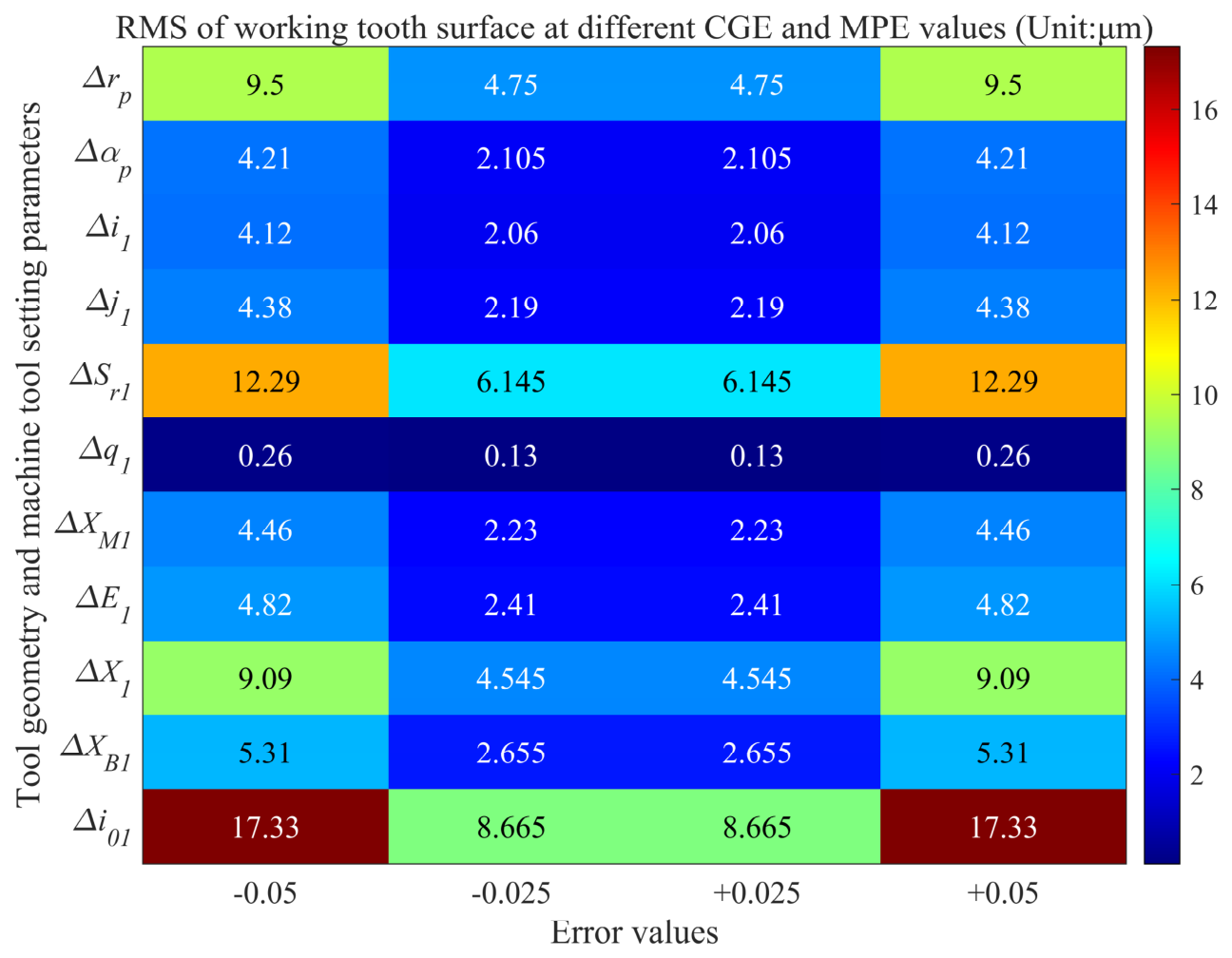
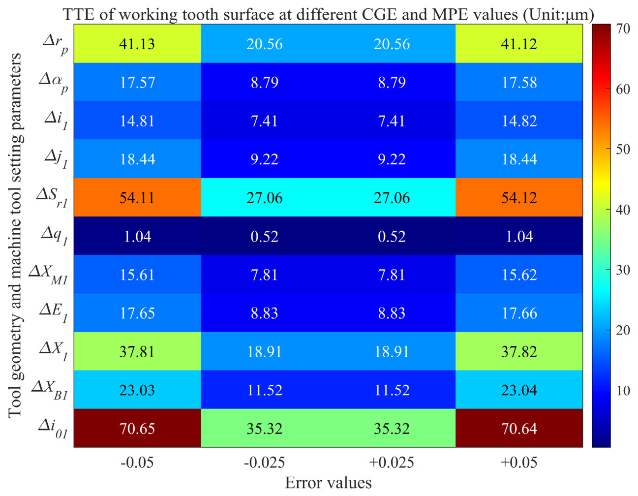
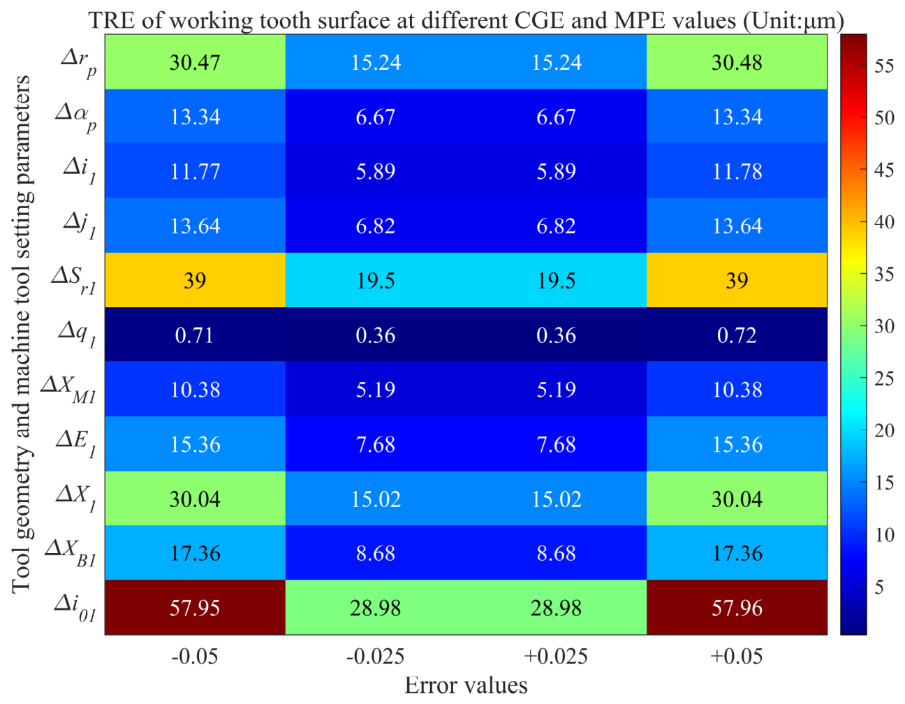
As illustrated in Figure 8, Figure 9 and Figure 10, the influence of CGE and MSE on RMS, TTE, and TRE exhibits a clear linear trend. Specifically, small variations in individual CGE or MSE parameters lead to approximately linear changes in these performance indicators. Moreover, the effects of positive and negative error values are nearly symmetric, indicating that the system responds uniformly to perturbations within this error range (It should be noted that the change value of the ratio of roll Δ i 01 in the figure is [ 0.005 , 0.0025 , + 0.0025 , + 0.005 ] ). Among all parameters, ratio of roll i 01 , radial distance S r 1 and cutting tool radius r p has the most significant impact on RMS, TTE and TRE. It should be noted that this paper treats second-order sensitivity as an interaction contribution (higher-order effect) and does not consider higher-order effects.
In actual machining processes, due to the inherent randomness of errors, the algorithmic model defines upper and lower bounds for each parameter. Under the assumption of a normal distribution, these parameters are randomly perturbed within their specified ranges. Specifically, the perturbation range for angular parameters is set to [−0.05, +0.05], and the same range is applied to linear parameters. Considering the significant influence of the rolling ratio on machining outcomes, its perturbation range is strictly limited to [−0.005, +0.005]. Based on these settings, a specific number of Sobol’ samples were generated for each processing parameter, as shown in Table 4. To ensure the accuracy of the analysis while controlling computational cost, the total sample size was set to N = 10,000, providing a solid foundation for the subsequent sensitivity analysis.
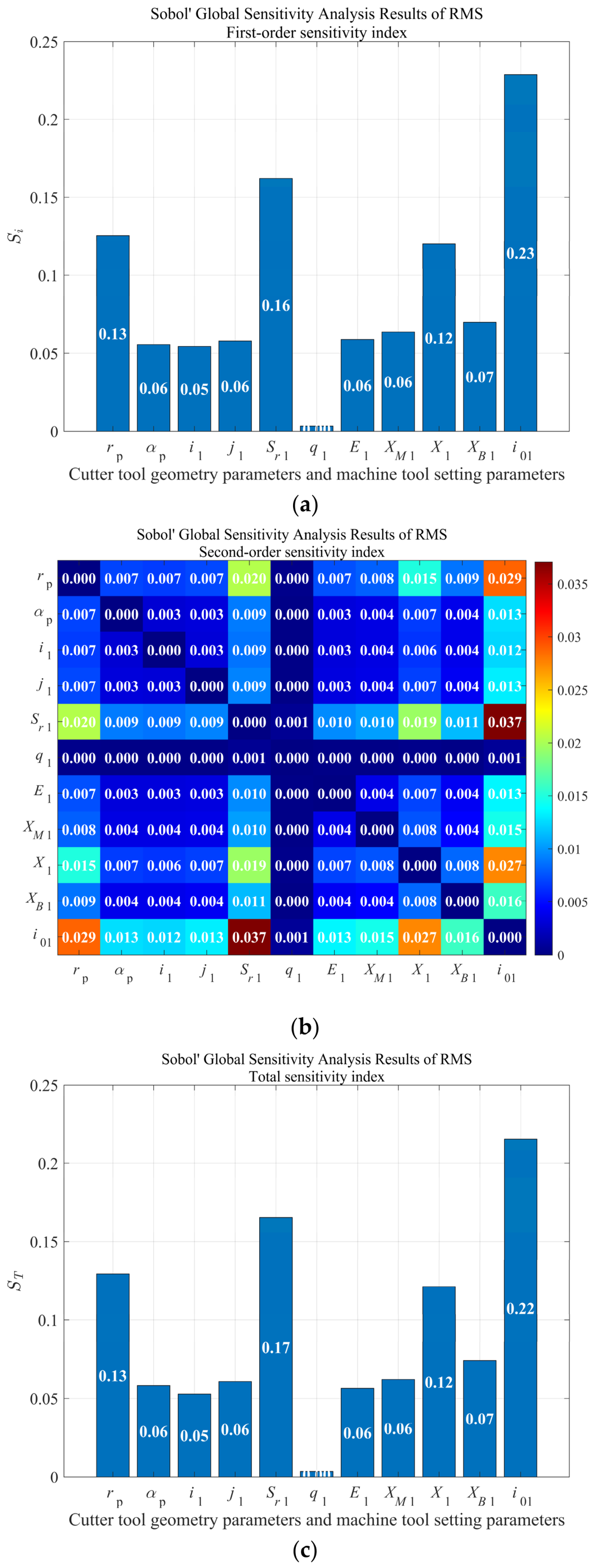
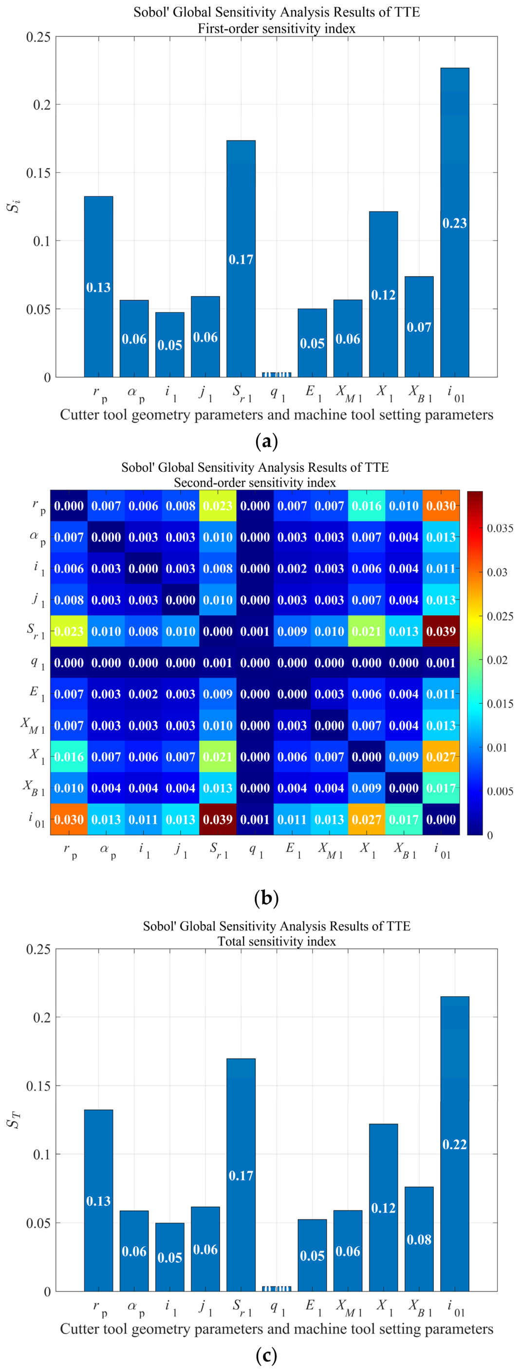
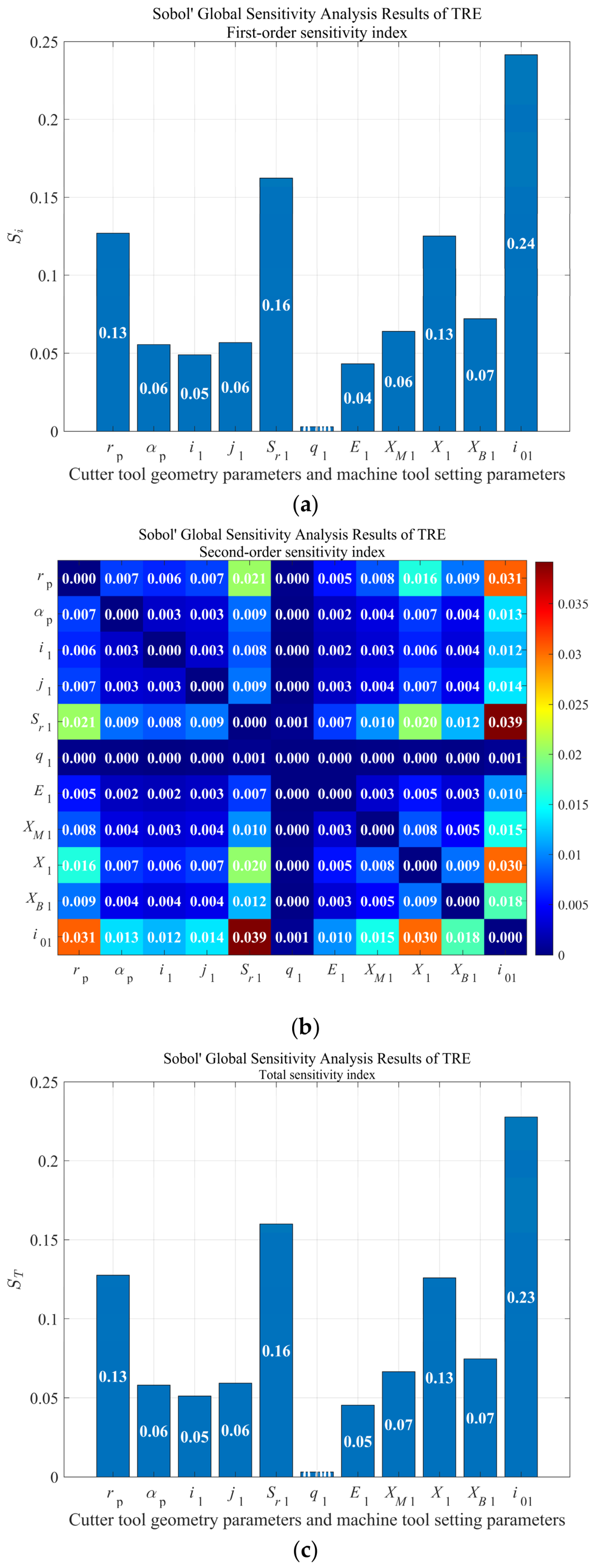
In this study, Sobol’ global sensitivity analysis (GSA) was employed to systematically evaluate the effects of cutter tool geometry errors (CGE) and machine tool setting parameters errors (MSE) on the RMS, TTE, and TRE of high reduction ratio hypoid gears. As shown in Figure 11, Figure 12 and Figure 13, the first-order sensitivity S i indices indicate that the ratio of roll i 01 , radial distance S r 1 , and cutting tool radius r p have the most significant impact on all three error metrics, while the machine center to back X 1 also exhibits notable sensitivity. Other parameters show comparatively minor effects, consistent with local sensitivity analysis results.
The higher-order interaction contribution sensitivity S i indices reveal strong interactions among the four key parameters i 01 , S r 1 , r p , and X 1 , which significantly influence tooth surface accuracy. By combining the S i and S i indices, the normalized total sensitivity indices S T i confirm that i 01 , S r 1 , and r p are the dominant factors, followed by X 1 . The remaining parameters have relatively limited influence. The overall ranking of parameter impact on errors is: i 01 > S r 1 > r p > X 1 > α p i 1 j 1 E 1 X M 1 X B 1 > q 1 .
These findings provide a scientific basis for optimizing critical parameters in the machining process of hypoid gears, contributing to improved tooth surface accuracy and transmission performance.

4. Tooth Surface Correction Method for HRHGs Considering CGE and MSE Based on Standard NSGA-II Algorithm

In the previous section, the influence of cutter tool geometric errors (CGE) and machine tool setting errors (MSE) on tooth surface accuracy was thoroughly investigated using the Sobol’ method. The results indicated that parameters i 01 , S r 1 , r p and X 1 have a pronounced effect on tooth surface accuracy, making it difficult to meet practical application requirements. To reduce the sensitivity of the tooth surface to these highly influential errors, this study proposes a modified NSGA-II-based tooth surface modification method for high reduction ratio hypoid gears (HRHGs), which simultaneously accounts for CGE and MSE, thereby enhancing the stability and reliability of the manufacturing process.

4.1. Objective Function Settings

Based on the foregoing analysis, variations in CGE and MSE exert a significant influence on the RMS, TTE, and TRE of the tooth surface. To reduce computational cost, four parameters with the highest sensitivity to these deviations are selected as optimization variables. A multi-objective optimization model is then formulated with the goal of simultaneously minimizing RMS, TTE, and TRE, so as to determine the optimal combination of cutter tool geometry parameters and machine tool setting parameters. The resulting multi-objective optimization problem can be expressed as:
F ( x ) = min f T T E ( x ) = TTE ( x ) min f T R E ( x ) = TRE ( x ) min f R M S ( x ) = RMS ( x ) s . t .   ( x ) min x ( x ) max Δ i 01 [ 0.005 , + 0.005 ] ,   Δ S r 1 [ 0.05 , + 0.05 ]   Δ r p [ 0.05 , + 0.05 ] ,   Δ X 1 [ 0.05 , + 0.05 ]  
where x represents the error vector between the cutter tool geometry and machine tool settings to be optimized; TTE, TRE and RMS represent the tooth top error, tooth root error, and tooth root mean square error for the parameter combination to be minimized; ( x ) min and ( x ) max represent the upper and lower bounds of the optimization variables, respectively.
In order to quantify the optimization termination condition, the relative error judgment criterion between the above error and the target tooth surface is introduced. When the objective function value of the optimal individual in the Pareto front solution set during i -th generation meets the following conditions, the optimization goal is considered to have been achieved and the optimization process can be terminated:
TTE i TTE opt TTE opt ε TTE     TRE i TRE opt TRE opt ε TTE   RMS i RMS opt RMS opt ε RMS
where TTE i , TRE i , RMS i represents the error value of the optimal individual of the i -th generation; TTE opt , TRE opt , RMS opt is the preset expected target value; ε TTE , ε TRE , ε RMS is the convergence accuracy threshold of the error.

4.2. Algorithm Settings

The traditional NSGA-II algorithm uses a randomly generated initial population. Due to its randomness, the spatial distribution is uneven, which affects the convergence speed and stability of the algorithm. To improve this, this paper adopts a population initialization method based on the optimal point set and generates the initial population individuals through the following formula:
X n j = x min j + mod ( 2 n cos ( θ ) , K ) × ( x max j x min j )
Among them, X n j is the j -th parameter in the n -th optimization parameter setting parameters; x max j and x min j are the upper and lower bounds of the j -th parameter, respectively; M is the number of parameters and M = 4 in this paper; K is the smallest prime number greater than 2 M + 3 and K = 11 in this paper; and θ is the angle variable.
In order to improve population diversity and local search capabilities during the evolution process, this paper further introduces non-uniform mutation and guided crossover strategies. In guided crossover, if the former is better than the latter among the two parent individuals p 1 ( x 1 1 , x 2 1 , x j 1 ) and p 2 ( x 1 2 , x 2 2 , x j 2 ) , the j -th gene value is generated by the following method.
c j 1 = x j 1 + v 1 c j 2 = x j 2 + v 2
where c j n represents the j -th gene of the n -th offspring, x j n represents the j -th gene of the n -th parent, and v n can be obtained by the following formula:
v 1 = 0.7 ( x j 1 x j 2 ) + 1.5 r 1 ( x j 1 ( x j 1 x j 2 2 ) ) + 0.6 r 2 ( x j 2 ( x j 1 x j 2 2 ) ) v 2 = 0.7 ( x j 1 x j 2 ) + 1.5 r 3 ( x j 1 ( x j 1 x j 2 2 ) ) + 0.6 r 4 ( x j 2 ( x j 1 x j 2 2 ) )
In terms of mutation operations, a non-uniform mutation method is used to achieve adaptive contraction of the intergenerational mutation range, enhancing the balance between early exploration and late convergence. The mutation operator is as follows:
c j = x j + ( x max j x j ) ( 1 r ( 1 t / i t e r ) b ) , s 0.5 c j = x j ( x j x min j ) ( 1 r ( 1 t / i t e r ) b ) , s > 0.5
Among them, c j is the j -th gene of the offspring; x j is the corresponding gene of the parent; r , s ( 0 , 1 ) are uniform random numbers; t is the current iteration number; i t e r is the maximum iteration number; b is the uniform control coefficient; and the control variation range decreases with the number of generations. The NSGA-II parameters were set as follows: the population size was 100, the maximum number of generations was 200, the crossover probability was 0.9, and the mutation probability was 0.1. The default crowding distance sorting mechanism was adopted. The termination criterion was defined as no significant improvement of the Pareto front over 20 consecutive generations (the variation in the objective function was less than 10 6 ). In addition, a fixed random seed (seed = 1) was used to ensure the repeatability of the optimization results.
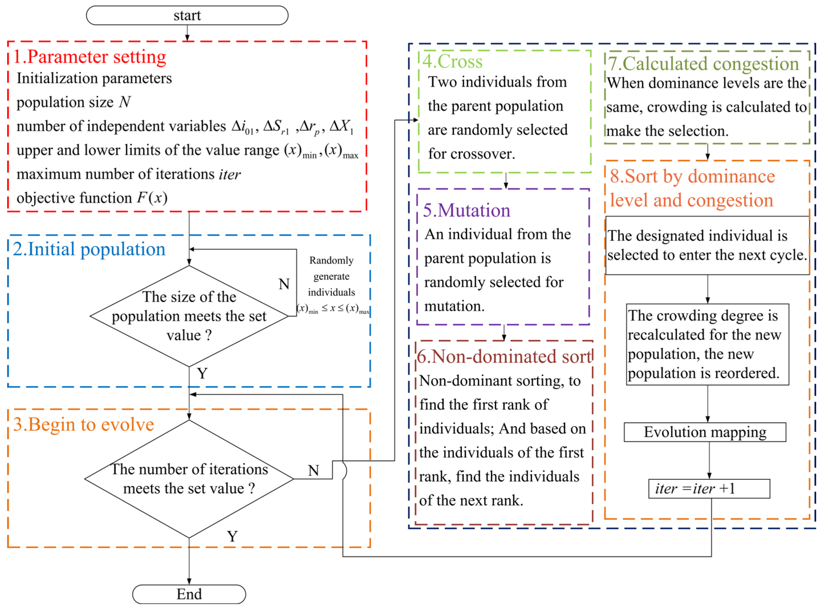
The specific NSGA-II algorithm flow is shown in Figure 14 below [25,26].

4.3. Pareto Front Solutions

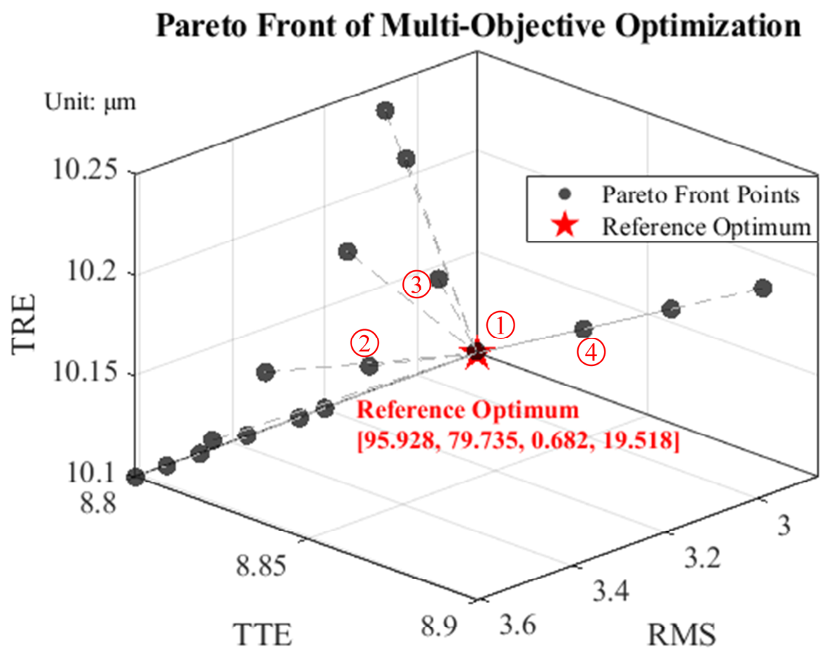
After performing the NSGA-II-based optimization, the Pareto front solution set was obtained, representing the trade-offs among RMS, TTE, and TRE. From the Pareto front, four representative optimal solutions were selected, as summarized in Table 5.
These solutions demonstrate the trade-offs between the three objectives, providing flexibility for selecting the optimal combination of cutter tool geometry and machine tool settings depending on practical manufacturing requirements.
Figure 15 illustrates the 3D Pareto front of RMS, TTE, and TRE, where the reference optimum point is marked in red. The spatial distribution of Pareto solutions highlights that all selected solutions are slightly worse than the reference optimum, which is consistent with the purpose of evaluating the sensitivity and trade-offs of the design parameters. In the four representative Pareto solutions, Solution 1 was selected as the final design because it exhibits the best performance in terms of the objective functions (TTE, TRE, and RMS).

5. Results and Discussion

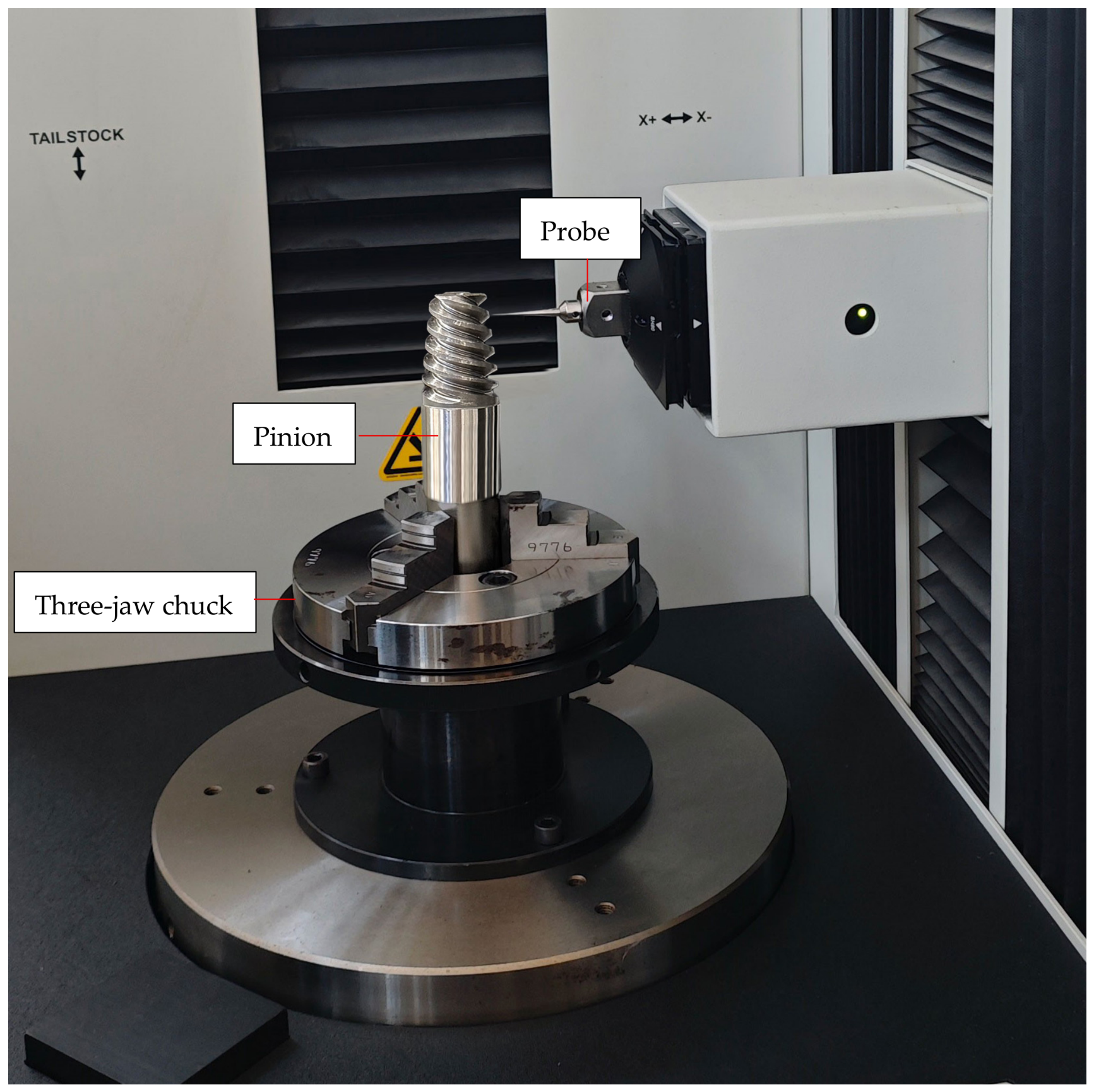
Combined with the GSA analysis results, this paper successfully identified the key tool geometry and machine setting parameters that influence the TTE, TRE, and RMS of high reduction ratio hypoid gears. By analyzing first-order and higher-order interaction contribution sensitivity indices, the contribution of each parameter to tooth surface error was further clarified. Based on these analysis results, this paper utilizes the standard NSGA-II algorithm to inversely determine the corrected values for cutter tool geometry and machine setting parameters to minimize tooth surface error and improve machining accuracy. The number of gear pairs used in the experiment was 3 × 60 tooth gear pairs. Each tooth surface was measured three times to ensure repeatability. The measurements were conducted using a Gleason 350 coordinate measuring machine.
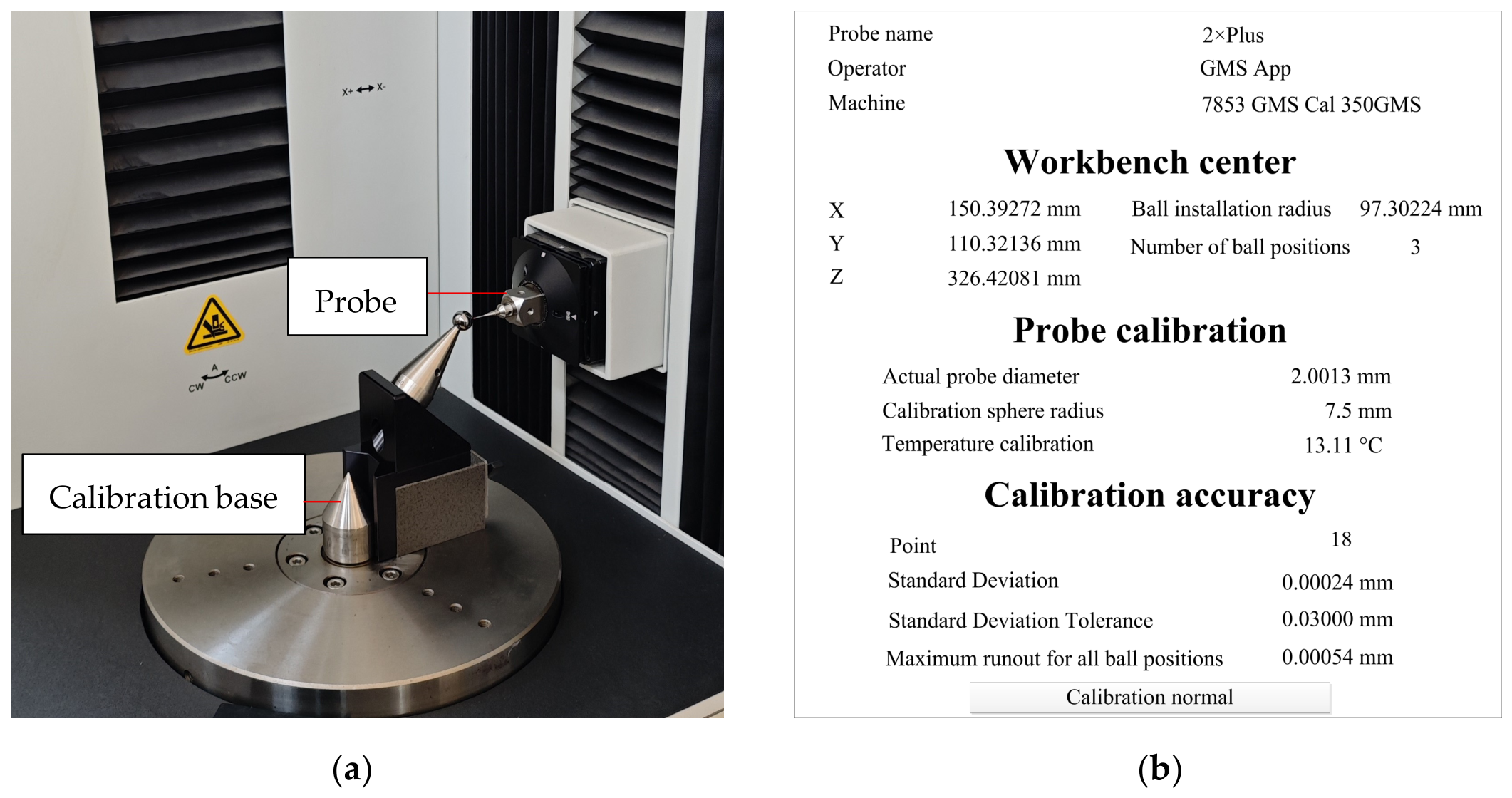
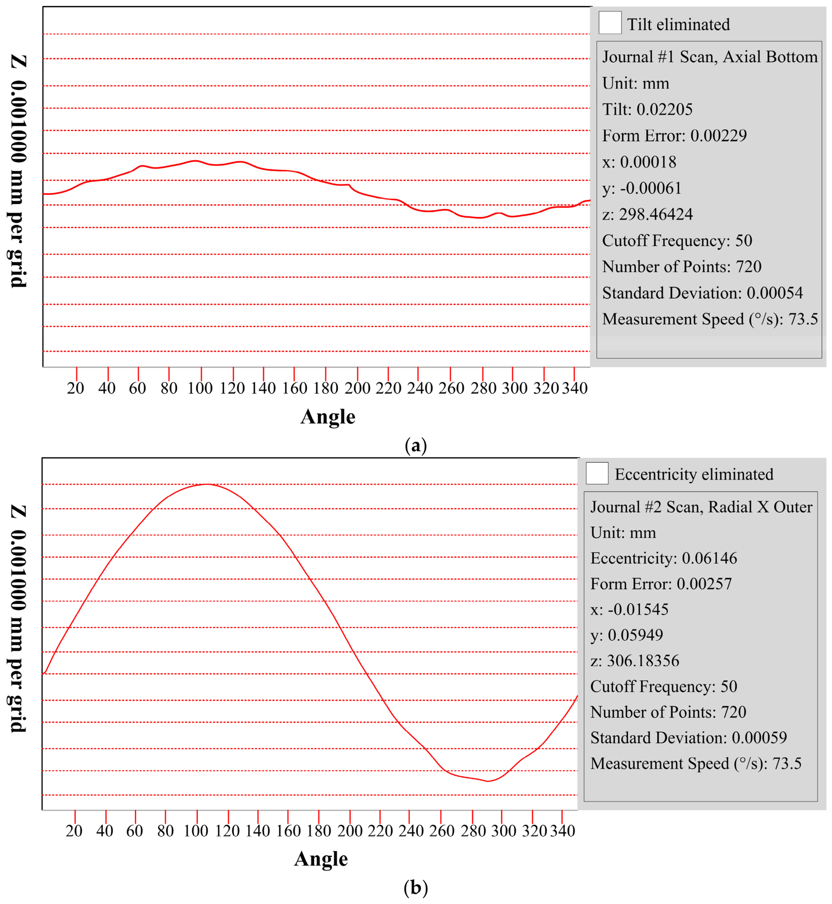
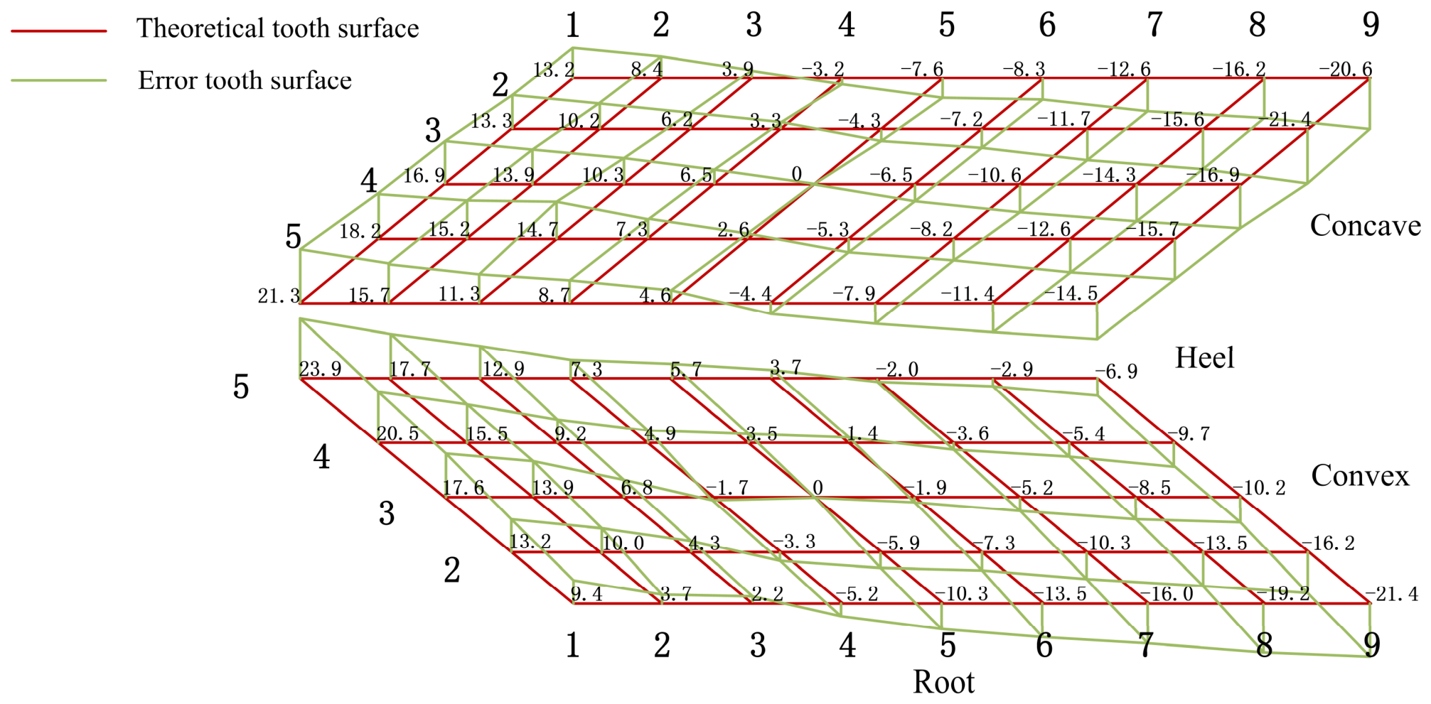
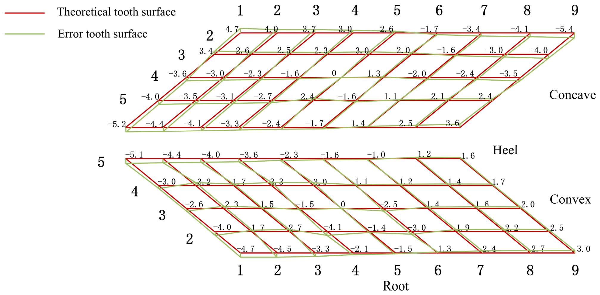
This paper takes the Gleason high reduction ratio hypoid gear pair as an example to verify the application-oriented method of combining Sobol’-based sensitivity analysis with NSGA-II optimization. The gear is manufactured using the forming method, whereas the pinion is manufactured using the generating method. The main geometric parameters of the gear pair are shown in Table 1, the initial values of the machine setting parameters for the pinion are shown in Table 2, and the corrected machining parameters and parameter variations are shown in Table 6. The iterative process of the NSGA-II algorithm is shown in Figure 14. Before conducting the measurement experiments, the measurement probe was calibrated, as shown in Figure 16a, and the calibration results are presented in Figure 16b, with a standard deviation of 0.00024 mm, to ensure the accuracy and reliability of the measurement system. Subsequently, the reference positions of the gear to be measured were determined, and the form deviations of the axial bottom and radial outer references were found to be 0.00229 mm and 0.00257 mm, respectively, as shown in Figure 17a,b, providing a basis for the subsequent tooth surface error detection; it should be noted that each division in Figure 16 represents 0.001 mm. The corrected cutter tool geometry and machine setting parameters further verify the effectiveness of this method. The results of measuring the actual machined pinion on a three-dimensional coordinate measuring machine are shown in Figure 18. The tooth surface error measurement results before and after correction for the critical machining errors are shown in Figure 19 and Figure 20, respectively. This effectively verifies the effectiveness and robustness of the proposed method. Multiple tooth surface measurements show that the tooth surface errors are significantly reduced after correction. The results with the smallest changes before and after correction are: the TTE on the concave side of the gear decreases from 35.8 to 8.80 μm; the TRE decreases from 33.8 to 10.10 μm; the RMS decreases from 10.73 to 2.87 μm; the TTE on the convex side of the gear decreases from 30.8 to 6.70 μm; the TRE decreases from 30.80 to 7.70 μm; and the RMS decreases from 9.08 to 2.44 μm, meeting practical application requirements. It should be noted that the above experiment was based only on repeated measurements of the same pair of manufactured gears. And, in order to ensure the modeling accuracy in the early stage of this paper, a 9 × 17 dot matrix was selected. In the actual measurement experiment, a 5 × 9 dot matrix can accurately represent the tooth surface accuracy [27].

6. Conclusions

This study proposes a comprehensive method for high reduction ratio hypoid gears. This method integrates Sobol’ sensitivity analysis with NSGA-II optimization to accurately identify the key error factors affecting tooth tip error (TTE), tooth root error (TRE), and root mean square deviation (RMS) of the tooth surface and to perform targeted optimization and compensation of the corresponding parameters. The main conclusions are as follows.
(1)
The proposed method simultaneously considers the combined effects of cutter tool geometry errors (CGE) and machine tool setting parameters errors (MSE) on TTE, TRE, and RMS. It effectively identifies key error sources and implements targeted optimization and compensation. Experimental results demonstrate that, after compensation, the tooth surface TTE, TRE, and RMS are significantly reduced, validating the effectiveness and robustness of this method in compensating gear manufacturing errors.
(2)
Based on Sobol’ global sensitivity analysis (GSA), this study identified four key parameters that most significantly affect TTE, TRE, and RMS: the ratio of roll i 01 , radial distance S r 1 , cutting tool radius r p , and machine center to back X 1 . Notably, the higher-order interaction contribution between i 01 and S r 1 has a particularly pronounced impact on tooth surface deviations, providing crucial insights for the formulation of optimization strategies.
(3)
After identifying the key parameters, the standard NSGA-II algorithm was used for multi-objective optimization to minimize TTE, TRE, and RMS. Multiple measurement results showed that the tooth surface error decreased significantly after correction. Multiple tooth surface measurement results showed that the tooth surface error decreased significantly after error correction. The minimum changes before and after correction are as follows: TTE on the concave side of the gear decreased from 35.8 to 8.80 μm; TRE decreased from 33.8 to 10.10 μm; RMS decreased from 10.73 to 2.87 μm; TTE on the convex side of the gear decreased from 30.8 to 6.70 μm; TRE decreased from 30.80 to 7.70 μm; and RMS decreased from 9.08 to 2.44 μm. These results demonstrate the effectiveness of the proposed error correction method.
Tooth surface machining accuracy is affected by multiple factors, including machine tool setting deviation, assembly error, thermal deformation, and fluctuations in operating conditions. Future research will comprehensively consider these error sources, conduct more systematic sensitivity evaluations, and develop more targeted tooth surface correction strategies to further improve machining quality and operational stability.

Author Contributions

All authors contributed to the study conception and design. Data collection and analysis were performed by J.L. and Y.W. The first draft of the manuscript was written by J.L., and all authors commented on previous versions of the manuscript. All authors have read and agreed to the published version of the manuscript.

Funding

The authors received no financial support for the research, authorship, and publication of this article.

Data Availability Statement

This manuscript does not involve research data support. I do not require research data support.

Conflicts of Interest

The authors declare no conflicts of interest.

References

  1. Litvin, F.L.; Zhang, Y.; Lundy, M.; Heine, C. Determination of settings of a tilted head cutter for generation of hypoid and spiral bevel gears. J. Mech. Des. 1988, 110, 495–500. [Google Scholar] [CrossRef]
  2. Litvin, F.L.; Fuentes, A.; Hayasaka, K. Design, manufacture, stress analysis, and experimental tests of low-noise high endurance spiral bevel gears. Mech. Mach. Theory 2006, 41, 83–118. [Google Scholar] [CrossRef]
  3. Fan, Q. Computerized modeling and simulation of spiral bevel and hypoid gears manufactured by Gleason face Hobbing process. J. Mech. Des. 2006, 128, 1315–1327. [Google Scholar] [CrossRef]
  4. Fan, Q.; DaFoe, R.S.; Swanger, J.W. Higher-order tooth flank form error correction for face-milled spiral bevel and hypoid gears. J. Mech. Des. 2008, 130, 072601. [Google Scholar] [CrossRef]
  5. Deng, X.Z.; Li, G.G.; Wei, B.Y.; Deng, J. Face-milling spiral bevel gear tooth surfaces by application of 5-axis CNC machine tool. Int. J. Adv. Manuf. Technol. 2014, 71, 1049–1057. [Google Scholar] [CrossRef]
  6. Su, J.Z.; Fang, Z.D.; Gu, J.G. Tooth surface correction for spiral bevel gears. Trans. Chin. Soc. Agric. Mach. 2010, 41, 201–203. [Google Scholar]
  7. Wang, Y.Z.; Lan, Z.; Hou, L.; Chu, X.; Yin, Y. An efficient honing method for face gear with tooth profile modification. Int. J. Adv. Manuf. Technol. 2017, 90, 1155–1163. [Google Scholar] [CrossRef]
  8. Li, T.X.; Li, J.B.; Deng, X.Z.; Yang, J.; Li, G.; Ma, W. A new digitized reverse correction method for hypoid gears based on a one-dimensional probe. Meas. Sci. Technol. 2017, 28, 125004. [Google Scholar] [CrossRef]
  9. Song, B.Y.; Tang, J.Y.; Rong, K.B.; Ding, H. A Machine-Settings Compensation Method for Reducing Machining Error of Spiral Bevel Gear Tooth Flank. J. Xi’an Jiaotong Univ. 2022, 56, 101–109. [Google Scholar] [CrossRef]
  10. Simon, V. Manufacture of Optimized Face-Hobbed Spiral Bevel Gears on Computer Numerical Control Hypoid Generator. ASME J. Manuf. Sci. Eng. 2014, 136, 031008. [Google Scholar] [CrossRef]
  11. Chen, P.; Wang, S.M.; Li, B.; Li, F. A novel geometric error compensation method for improving machining accuracy of spiral bevel gear based on inverse kinematic model. Int. J. Adv. Manuf. Technol. 2023, 127, 4339–4355. [Google Scholar] [CrossRef]
  12. Miro, S.; Hartmann, D.; Schanz, T. Global sensitivity analysis for subsoil parameter estimation in mechanized tunneling. Comput. Geotech. 2014, 56, 80–88. [Google Scholar] [CrossRef]
  13. Zou, X.; Zhao, X.; Li, G.; Li, Z.; Sun, T. Sensitivity analysis using a variance-based method for a three-axis diamond turning machine. Int. J. Adv. Manuf. Technol. 2017, 92, 4429–4443. [Google Scholar] [CrossRef]
  14. Zou, X.; Zhao, X.; Wang, Z.; Li, G.; Hu, Z.; Sun, T. Error distribution of a 5-axis measuring machine based on sensitivity analysis of geometric errors. Math. Probl. Eng. 2020, 2020, 8146975. [Google Scholar] [CrossRef]
  15. Li, X.; Yuan, J.T.; Wang, Z.H. Optimal design method for geometric errors of horizontal machining center based on Sobol method and IPSO. Int. J. Adv. Manuf. Technol. 2024, 131, 6091–6102. [Google Scholar] [CrossRef]
  16. Han, J.H.; Wang, L.P.; Ma, F.J.; Ge, Z.Y.; Wang, D.; Li, X.K. Sensitivity analysis of geometric error for a novel slide grinder based on improved Sobol method and its application. Int. J. Adv. Manuf. Technol. 2022, 121, 6661–6684. [Google Scholar] [CrossRef]
  17. Jiang, X.G.; Cui, Z.W.; Wang, L.; Liu, C.; Li, M.J.; Liu, J.; Du, Y. Critical geometric errors identification of a five-axis machine tool based on global quantitative sensitivity analysis. Int. J. Adv. Manuf. Technol. 2022, 119, 3717–3727. [Google Scholar] [CrossRef]
  18. Li, G.L.; Wu, C.F.; Xu, K.; Ran, Q.F.; Cao, B. Pivotal errors identification of the face gear worm grinding machine tool with a piecewise sensitivity analysis. Mech. Mach. Theory 2023, 181, 105206. [Google Scholar] [CrossRef]
  19. He, X.B.; Zhang, K.; Li, R.R.; Tang, W.B.; Peng, Y.F. Priority Analysis and Optimization for Accuracy Allocation of Precision Grinding Machine Considering Manufacturing Accuracy and Cost. Int. J. Precis. Eng. Manuf. 2025, 26, 599–612. [Google Scholar] [CrossRef]
  20. Kim, S.; Kim, Y.; Jeon, H.K.; Jang, T.S.; Lee, C.H.; Sugita, N. Development of Volumetric Accuracy Enhancement Method for a 5-Axis Machine Tool Based on Sensitivity Analysis and Extraction Algorithm. Int. J. Precis. Eng. Manuf. 2025, 26, 2671–2687. [Google Scholar] [CrossRef]
  21. Mao, Y.H.; Wang, Y.G.; Huang, X. A precise solving method for helical groove process based on an improved NSGA-II algorithm. Int. J. Adv. Manuf. Technol. 2025, 137, 1215–1228. [Google Scholar] [CrossRef]
  22. Ding, H.; Tang, J.Y.; Zhong, J. An accurate model of high-performance manufacturing spiral bevel and hypoid gears based on machine setting modification. J. Manuf. Syst. 2016, 41, 238–249. [Google Scholar] [CrossRef]
  23. Ding, H.; Tang, J.Y.; Shao, W.; Zhou, Y.S.; Wan, G.X. Optimal modification of tooth flank form error considering measurement and compensation of cutter geometric errors for spiral bevel and hypoid gears. Mech. Mach. Theory 2017, 118, 14–31. [Google Scholar] [CrossRef]
  24. Pan, Q.Q.; Zheng, S.C.; Liu, X.J. Deep-coupling neural network and genetic algorithm based on Sobol’-PR for reactor lightweight optimization. Appl. Soft Comput. 2024, 167, 112458. [Google Scholar] [CrossRef]
  25. Yu, B.; Li, H.S.; Gu, C.Z.; Shen, A.; Zhang, S.; Liu, X.; Li, J.B.; Ba, K.X.; Ma, G.L.; Kong, X.D. Design of lightweight hydraulic power unit for legged robots based on the Sobol sensitivity analysis. Energy Convers. Manag. 2025, 328, 119620. [Google Scholar] [CrossRef]
  26. Chua, P.C.; Moon, S.K.; Ng, Y.T.; Lopez, M. Strategic Production Process Design with Additive Manufacturing in a Make-to-Stock Environment. ASME J. Manuf. Sci. Eng. 2023, 145, 111009. [Google Scholar] [CrossRef]
  27. Wu, S.X.; Yan, H.J.; Wang, Z.Y.; Bi, Z.G.; Chen, Z.; Zhu, P.F. Tooth surface error correction of hypoid gears machined by duplex helical method. J. Cent. South Univ. 2021, 28, 1402–1411. [Google Scholar] [CrossRef]
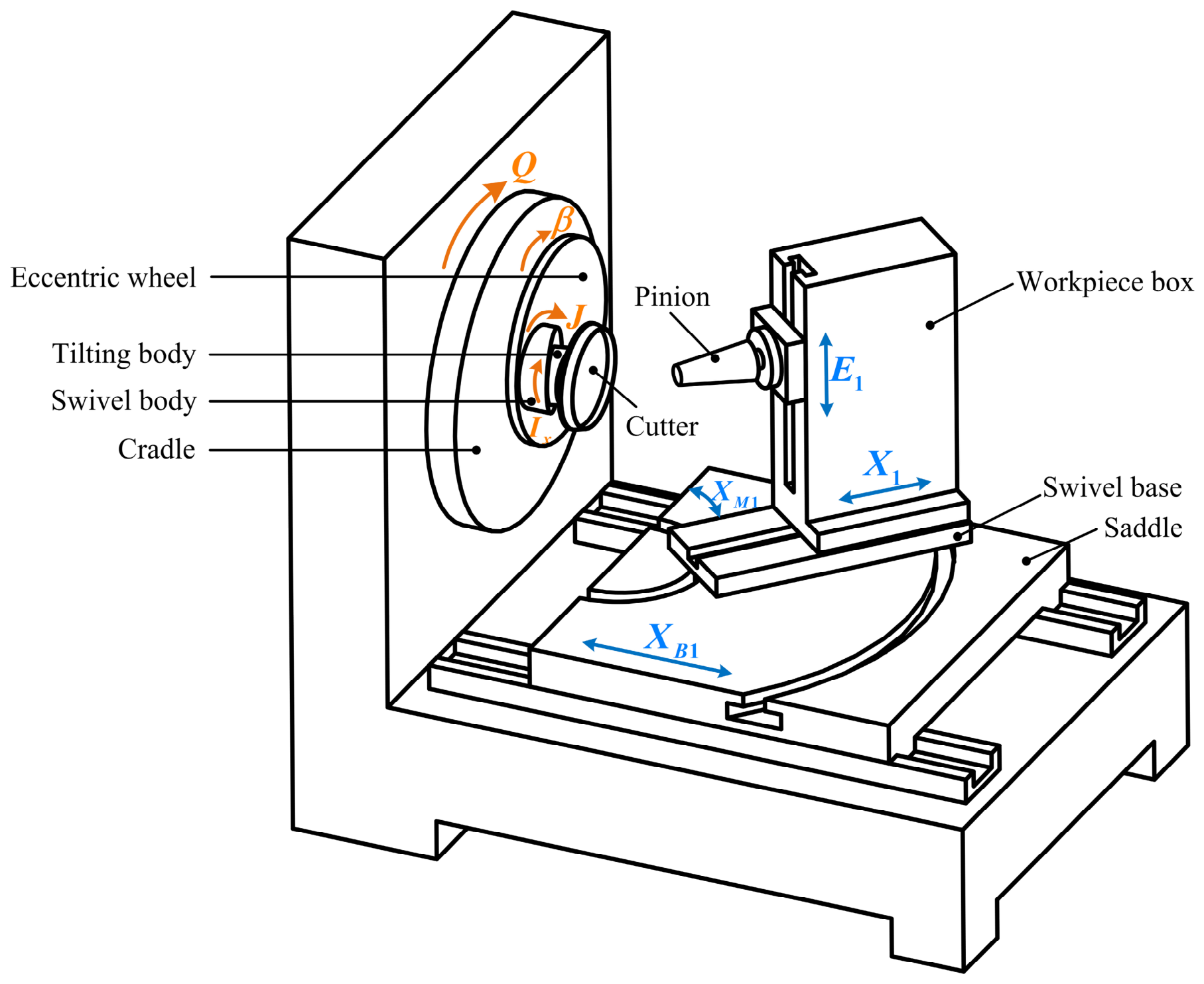
Figure 1. Main structure of the Gleason spiral bevel gear milling machine. X M 1 —Machine root angle, E 1 —Blank offset, X 1 —Machine center to back, X B 1 —Sliding base, I x —Tilting body angle, J —Swivel body angle, β —Eccentric wheel angle, Q —Cradle angle.
Machines 14 00792 g001
Figure 2. Cutter geometry for machining the pinion concave surface.
Machines 14 00792 g002
Figure 3. Coordinate systems involved in the machining process of the pinion tooth surface.
Machines 14 00792 g003
Figure 4. Schematic of the pinion model generation process. (a) Rotating projection; (b) 9 × 17 point cloud; (c) tooth surface reconstruction; (d) a pinion model.
Machines 14 00792 g004
Figure 5. Schematic diagram of RMS calculation based on tooth surface normal deviation.
Machines 14 00792 g005
Figure 6. Effect of CGE on work surface RMS, TTE and TRE.
Machines 14 00792 g006
Figure 7. Effect of MSE on work surface RMS, TTE and TRE.
Machines 14 00792 g007aMachines 14 00792 g007bMachines 14 00792 g007cMachines 14 00792 g007d
Figure 8. RMS of working tooth surface at CGE and MSE values.
Machines 14 00792 g008
Figure 9. TTE of working tooth surface at CGE and MSE values.
Machines 14 00792 g009
Figure 10. TRE of working tooth surface at CGE and MSE values.
Machines 14 00792 g010
Figure 11. Global sensitivity analysis results of RMS.
Machines 14 00792 g011
Figure 12. Global sensitivity analysis results of TTE.
Machines 14 00792 g012
Figure 13. Global sensitivity analysis results of TRE.
Machines 14 00792 g013
Figure 14. The specific NSGA-II algorithm flow.
Machines 14 00792 g014
Figure 15. Three-dimensional Pareto front of RMS, TTE, and TRE.
Machines 14 00792 g015
Figure 16. Probe calibration process and calibration results. (a) Calibration procedure; (b) calibration results.
Machines 14 00792 g016
Figure 17. Form deviations of the reference positions of the gear. (a) Axial bottom reference; (b) radial outer reference.
Machines 14 00792 g017
Figure 18. Measurement of the tooth surface discrete points after actual machining.
Machines 14 00792 g018
Figure 19. Tooth surface error diagram before compensation.
Machines 14 00792 g019
Figure 20. Tooth surface error diagram after compensation.
Machines 14 00792 g020
Table 1. Main geometric parameters of pinion.
ItemValue
Number of pinion teeth3
Number of gear teeth60
Nominal pressure angle/(°)20
Mean spiral angle/(°)60
Shaft angle/(°)90
Pinion offset/mm30
Face width/mm35.8
Pitch distance/mm189.36
Table 2. Initial value of machine tool setting parameters of pinion.
ItemValue
ConcaveConvex
Cutting tool radius/mm95.97284.973
Cutting tool profile angle/(°)1435
Tilt angle/(°)−4.92−6.86
Swivel angle/(°)116.3482.12
Radial distance/mm79.7175.94
Center roll position/(°)106.4198.52
Blank offset/mm27.9832.24
Machine root angle/(°)−3.66−3.48
Machine center to back/mm0.71−0.16
Sliding base/mm11.7316.11
Ratio of roll19.5220.29
Table 3. The values of the CGE and MSE.
Item Δ ξ l Error Values
Cutting tool radius/mm Δ r p [ 0.05 , 0.025 , + 0.025 , + 0.05 ]
Cutting tool profile angle/(°) Δ α p
Tilt angle/(°) Δ i 1
Swivel angle/(°) Δ j 1
Radial distance/mm Δ S r 1
Blank offset/mm Δ E 1
Machine root angle/(°) Δ X M 1
Machine center to back/mm Δ X 1
Sliding base/mm Δ X B 1
Ratio of roll Δ i 01 [ 0.005 , 0.0025 , + 0.0025 , + 0.005 ]
Table 4. Random perturbation point values that satisfy normal distribution.
Item r p α p i 1 j 1 S r 1
Value95.95914.045−4.897116.35079.676
96.01914.033−4.949116.30879.678
95.95113.987−4.924116.36979.680
95.92913.986−4.958116.37679.722
96.01113.997−4.963116.36179.736
95.93313.953−4.906116.32179.711
Item q 1 E 1 X M 1 X 1 X B 1 i 01
Value106.37627.936−3.6230.72011.75119.515
106.39027.982−3.6670.68911.74119.516
106.41127.989−3.7050.71011.69719.524
106.39327.936−3.6690.73611.68319.515
106.41628.007−3.6790.69311.70319.521
106.45127.955−3.6280.75411.75319.523
Table 5. Representative Pareto front solutions of RMS, TTE, and TRE.
Solution r p S r 1 X 1 i 01 RMSTTETRE
195.92879.7350.68219.5182.878.810.1
295.93279.7340.68219.5193.158.810.12
395.93079.7380.68419.5203.148.810.14
495.93179.7350.68119.5212.898.8210.13
Table 6. Values of cutter tool geometry machine tool setting parameters after correction.
ItemBefore CorrectionAfter CorrectionChanging Value
Cutting tool radius/mm95.97295.928−0.044
Radial distance/mm79.7179.7350.025
Machine center to back/mm0.710.682−0.028
Ratio of roll19.5219.518−0.002
Disclaimer/Publisher’s Note: The statements, opinions and data contained in all publications are solely those of the individual author(s) and contributor(s) and not of MDPI and/or the editor(s). MDPI and/or the editor(s) disclaim responsibility for any injury to people or property resulting from any ideas, methods, instructions or products referred to in the content.