Article

Development and Validation of a Vision-Based Dynamic Defect Detection and Robotic Sorting System for Small Irregular Stamped Parts


1
School of Electronic Information and Electrical Engineering, Chengdu University, Chengdu 610106, China
2
School of Mechanical Engineering, Chengdu University, Chengdu 610106, China
3
Division of Logistics and Transportation, Shenzhen International Graduate School, Tsinghua University, Shenzhen 518055, China
*
Author to whom correspondence should be addressed.
Machines 2026, 14(7), 784; https://doi.org/10.3390/machines14070784
Submission received: 10 June 2026 / Revised: 9 July 2026 / Accepted: 10 July 2026 / Published: 13 July 2026
(This article belongs to the Section Robotics, Mechatronics and Intelligent Machines)

Abstract

Automatic inspection of small, irregular stamped parts remains challenging due to their compact size, random orientation on conveyors, and susceptible metallic surface reflections, coupled with local, weak, and densely distributed defects. This study presents an integrated vision-based dynamic defect detection and robotic sorting system to address these issues. The framework seamlessly unifies conveyor-based image acquisition, YOLO-CGMS-based defect recognition, hand–eye coordinate mapping, and Delta robot trajectory planning. To drive real-time visual perception, the YOLO-CGMS architecture modifies the YOLOv8n baseline by incorporating C2f-CRM, GRF-SPPF, MCA, and Inner-GIoU modules, optimizing small-defect feature extraction and bounding-box regression. Evaluated on a factory-collected dataset, YOLO-CGMS achieved an mAP50 of 88.7% and an inference speed of 236.23 frames/s, using only 2.8 M parameters and 7.3 GFLOPs. Compared with YOLOv8n, mAP and execution speed increased by 5.1 percentage points and 12.18 frames/s, respectively, while the parameter size and computational cost dropped by 0.2 M and 0.8 GFLOPs. Furthermore, physical sorting capability was validated on a developed prototype platform, yielding a mean hand–eye positioning error of 2.66 mm. Across 200 dynamic trials, the system successfully sorted 161 defective workpieces, translating to an 80.5% success rate and a mean cycle time of 2.6 s per part. These findings confirm that the proposed system reliably links closed-loop visual perception with physical execution, providing a practical foundation for the automated quality control of complex stamped components.

1. Introduction

Small irregular stamped parts are extensively utilized in industries such as automotive, marine, and aerospace. However, surface defects, including edge defects, hole misalignments, scratches and so on are inevitable during the production process [1]. These defects severely compromise the mechanical performance (e.g., strength and toughness) of the stamped parts, leading to inconsistent product quality and decreased production efficiency. Accurate defect detection for small irregular stamped parts enables timely identification of defects and operational errors during production, thus improving mechanical performance and reducing production costs.
Convolutional neural networks have been instrumental in transforming surface defect detection in deep learning, which has advanced significantly in recent years [2]. Deep learning-based object detection algorithms now fall into two categories: single-stage and two-stage [3]. Single-stage approaches include the YOLO series [4] and SSD [5], while two-stage approaches involve methods like R-CNN [6], Fast R-CNN [7], and Faster R-CNN [8]. Compared to two-stage methods, the characteristic of single-stage methods is high processing efficiency and more applicable in real-time detection. In 2020, the introduction of the Detection Transformer (DETR) [9] represented a breakthrough in computer vision, leading to significant advancements in defect detection tasks. Chen et al. [10] suggested a technique for detecting metal surface flaws that combines adaptive convolution and anchor box networks, enabling the automatic identification and combination of characteristics at several scales. This approach effectively improves the model’s ability to detect defects of various sizes and shapes. By utilizing this method, the model can accurately extract and fuse multi-scale features when processing diverse defect images, greatly improving metal surface flaw detection’s precision and resilience. Wang et al. [11] introduced the Collaborative Learning Attention Network (CLANet), the first to combine depth and visual information for rail surface defect segmentation. Although this approach significantly improved segmentation accuracy, it was limited by the structural complexity, low detection efficiency, and poor robustness of segmentation models. Liu et al. [12] proposed a progressive YOLO model, which first enhances the YOLOv3-dense model for insulator location detection, and then optimizes the YOLOv4-tiny model to detect insulator defects. These two models are processed in a progressive manner. The suggested approach shows encouraging results in fault detection and insulator identification for transmission line systems. Li et al. [13] recommended M2-BL-YOLOv4, a lightweight adaptation of YOLOv4 tailored for detecting aluminum surface defects. Their method introduced inverted residual structures into the backbone network, significantly reducing model complexity while increasing the speed of detection. Liu et al. [14] introduced a surface defect detection strategy using YOLOv4 and MobileNet series (MobileNetv1 [15], MobileNetv2 [16], MobileNetv3 [17]) as the backbone. This approach reduced network parameters while enhancing feature extraction capabilities. Li et al. [18] developed a novel defect detection system for aviation connectors by YOLOv5, where a generalised efficient aggregation layer network was used in place of the basic convolution attention module. This modification effectively aggregated multi-scale and multi-level features while retaining the depth information of the entire network. Chao et al. [19] developed the RDD-YOLO model, achieving remarkable performance on steel surfaces by enhancing the YOLOv5 architecture with a decoupled head structure and a Dual Feature Pyramid Network. Wu et al. [20] used an enhanced YOLOv7-tiny model to identify insulator flaws online. The SIoU loss function greatly increased the operating efficiency by accelerating the anchor box regression speed.
Although existing YOLO-based methods have improved the accuracy and efficiency of industrial defect detection, most studies remain limited to static image recognition. In practical production, small irregular stamped parts move continuously on a conveyor belt with random positions and postures. Therefore, defect detection alone is insufficient for online inspection. A practical system should further convert visual detection results into actuator-level position information and complete real-time sorting. This requires the integration of visual sensing, lightweight detection, coordinate mapping, motion planning, and robotic execution.
To address this requirement, this study develops a vision-sensor-guided real-time defect detection and Delta-robot sorting system for small irregular stamped parts. A lightweight YOLO-based model is designed as the core visual perception module to improve the detection of small and densely distributed defects. The detected pixel coordinates are then transformed into the Delta robot coordinate system, enabling sorting decision-making and dynamic pick-and-place execution. In this way, the proposed system shifts from image-level defect recognition to a closed-loop inspection and sorting process for practical industrial application.
The main contributions of this study are summarized as follows:
(1)
A vision-sensor-guided real-time inspection and sorting system is developed for small irregular stamped parts, integrating image acquisition, defect detection, coordinate mapping, trajectory planning, and Delta-robot execution.
(2)
A lightweight YOLO-based defect detection model is designed as the core perception module to enhance small-defect feature extraction while maintaining real-time inference performance.
(3)
A camera-to-robot coordinate mapping strategy is established to convert detected pixel coordinates into executable sorting positions for the Delta robot.
(4)
A physical prototype is built and validated through dynamic experiments, demonstrating the feasibility of the proposed system in terms of detection accuracy, positioning performance, sorting success rate, and real-time processing capability.

2. Materials and Methods

2.1. System Overview

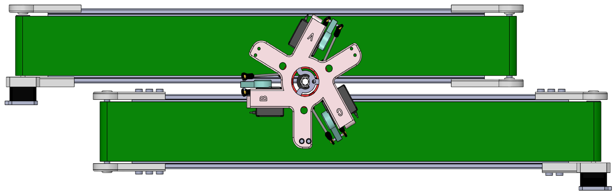
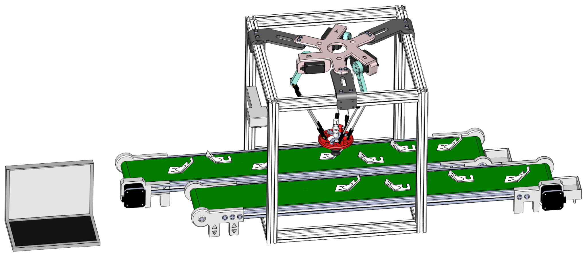
The proposed vision-based dynamic defect detection and robotic sorting system was developed for the online inspection of small irregular stamped parts. As shown in Figure 1, the system consists of a laptop, stepper motors, a conveyor, small irregular stamped parts [21], an industrial camera, a camera fixture, an aluminum-alloy frame, a Delta robot, a pneumatic suction device, and collection bins. According to the functional layout, the system can be divided into three main units: the conveyor transport unit, the machine vision recognition unit, and the Delta robot sorting unit [22].
During operation, the conveyor transports stamped parts through the image acquisition area at a constant speed. The industrial camera captures surface images of the moving workpieces and transmits them to the laptop for defect recognition. Once a defective workpiece is detected, its pixel coordinates are obtained and transformed into the base coordinate system of the Delta robot [23]. The control unit then drives the Delta robot to move to the target position, where the pneumatic suction device picks up the defective workpiece and places it into the collection bin. Therefore, the system forms a complete workflow from image acquisition and defect detection to coordinate mapping and robotic sorting.

2.2. Image Acquisition and Dataset Construction

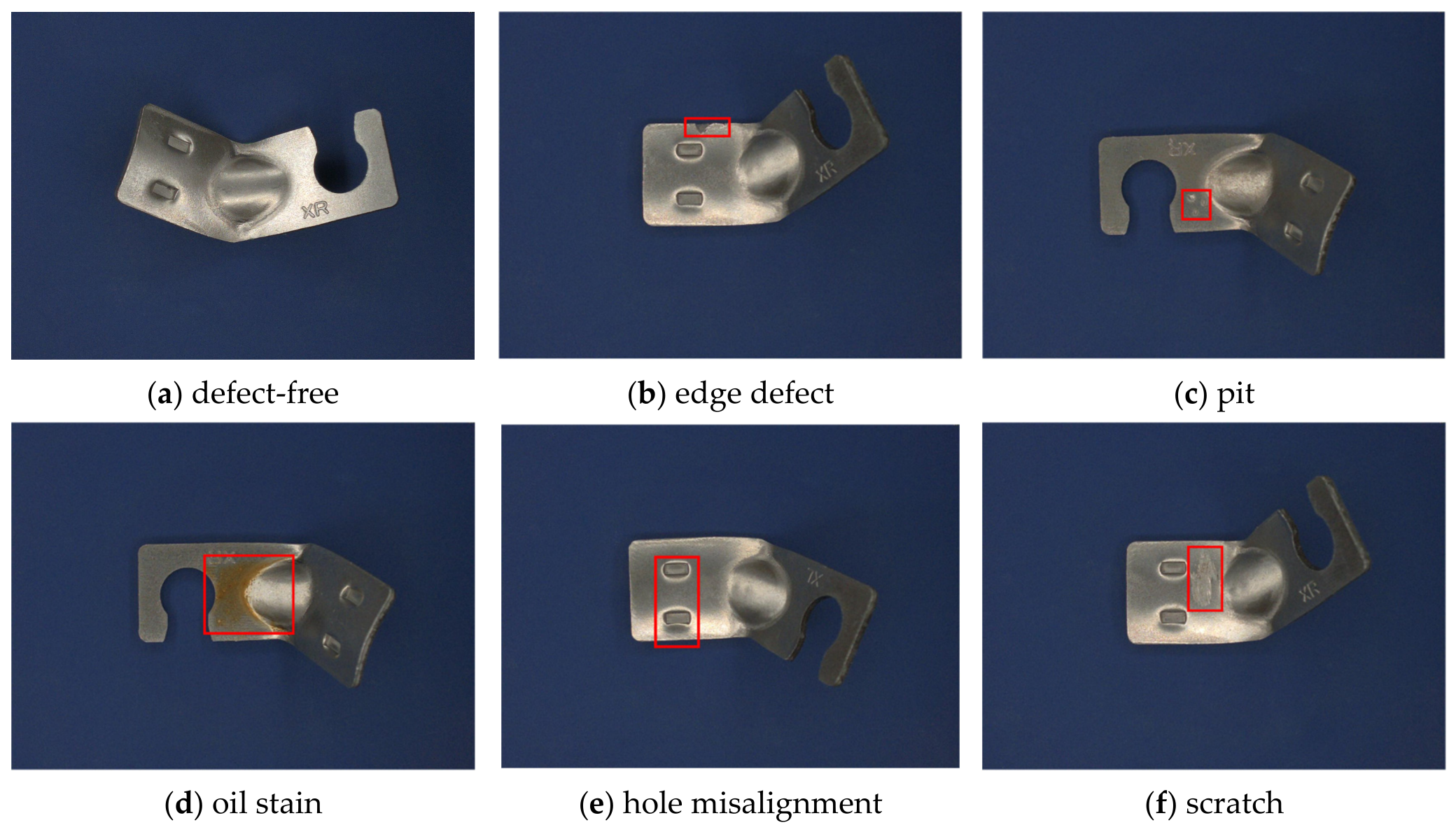
The detection algorithm in this study targets the surface defects of small irregular stamped parts manufactured by Chengdu Juxin Machinery Equipment Co., Ltd. (Chengdu, China). These parts are characterized by irregular shapes, various types of defects, and small defect sizes. Figure 2 shows the common types of defects, including edge defects, pits, oil stains, misaligned holes, and scratches.
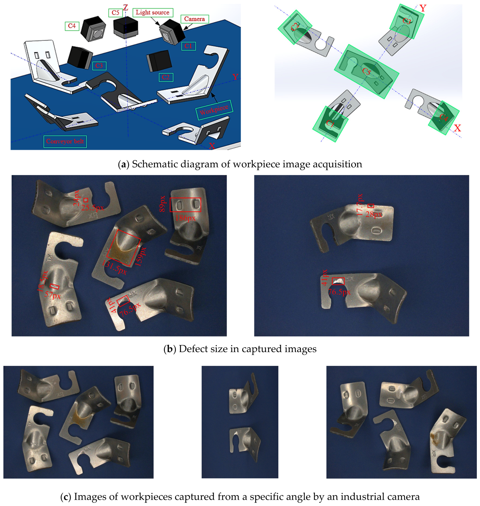
Prior to the image acquisition of small irregular stamped parts, the minimum imaging range of the industrial camera was determined based on the conveyor belt’s width of 11.5 cm, placing the industrial camera 33 cm above the conveyor belt. Due to the random and uncertain positioning and orientation of the small irregular stamped parts on the conveyor belt, as well as the relatively small surface defects (the varying defect sizes in the acquired images are shown in Figure 3b), it is challenging for a single-angle industrial camera to capture all defects on the surfaces of the parts. To improve the precision of surface fault identification in small irregular stamped parts, this study employed multiple industrial cameras to capture multi-angle images of the part surfaces, as shown in Figure 3a. As the parts move through the image acquisition region on the conveyor belt, five frames per second are captured by each camera. Given that each part spends 3 s passing through the acquisition area, up to 100 images and at least 75 images can be captured per part. Each image has a resolution of 1280 × 960 pixels and is 129 KB in size. Consequently, when surface defects occur, the industrial cameras capture defect images from multiple angles, as demonstrated in Figure 3c. This multi-angle image acquisition method significantly enhances the detection capability for surface defects on small irregular stamped parts, improving both the comprehensiveness and accuracy of the detection process.
Although a large number of raw images were obtained during continuous acquisition, not all frames were directly used for model training. Since each workpiece was recorded in multiple consecutive frames while passing through the imaging area, many images contained highly similar workpiece positions, defect appearances, illumination conditions, and viewing angles. Directly using all raw images would introduce excessive redundancy and increase the training cost, but would not necessarily improve the generalization ability of the detection model. Therefore, a representative image subset was constructed after redundancy reduction and quality screening.

2.3. YOLO-Based Defect Detection Module

2.3.1. Overall Structure of YOLO-CGMS

In the proposed detection and sorting system, the defect detection model serves as the core visual perception module. Its function is to identify surface defects in the images acquired by the industrial camera and to output the defect category and pixel coordinates of defective workpieces for subsequent coordinate transformation and robotic sorting. Considering the requirements of real-time detection, model lightweighting, and small-defect recognition, YOLOv8n was selected as the baseline network, and an improved YOLO-based model, named YOLO-CGMS, was constructed for the surface defect detection task of small irregular stamped parts.
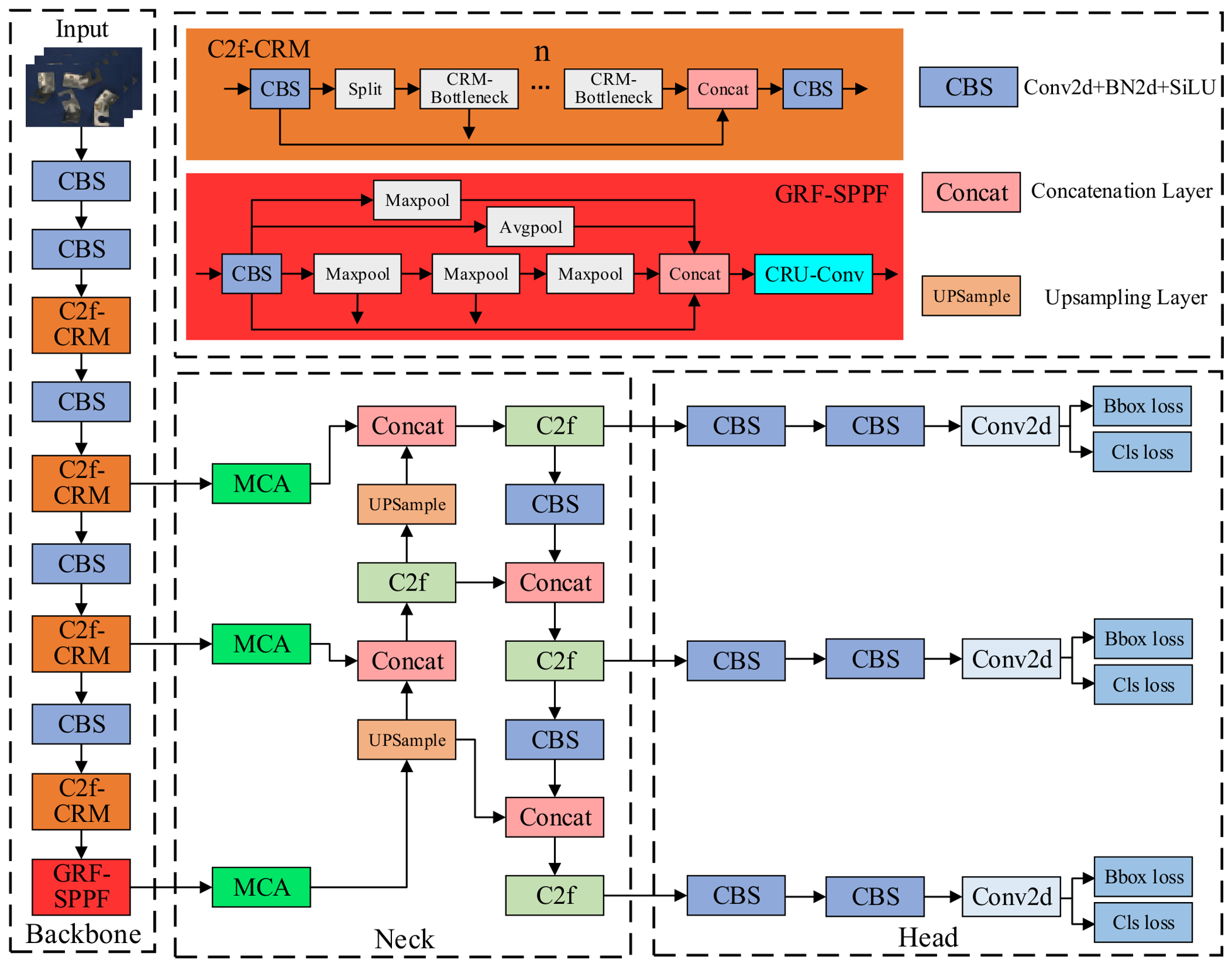
The surface defect images of small irregular stamped parts are characterized by small target regions, diverse defect morphologies, dense defect distribution, and interference from complex backgrounds. To improve the detection ability of the model under these conditions, YOLO-CGMS introduces improvements in feature extraction, multi-scale feature fusion, attention representation, and bounding-box regression. The overall structure of the proposed model is shown in Figure 4.
This model incorporates several enhancements in the Backbone section, including the C2f-CRM module and the global receptive field spatial pooling pyramid module. The introduction of a multi-dimensional collaborative attention module in multi-scale feature fusion, and the CIoU loss function is optimized. First, the CRM-Bottleneck replaces the original Bottleneck in the Backbone, integrating channel reconstruction convolution with a multi-dimensional collaborative attention mechanism. This effectively reduces channel redundancy among features and enhances the extraction of multi-scale information enriched with contextual details, thereby alleviating problems associated with the omission and misidentification in tiny objects. Second, the SPPF module is improved to extend the Backbone’s receptive field, improving the network’s capacity to record global feature data. This provides richer feature information, thereby improving the detection accuracy of various defects such as edge defects, pits, oil stains, hole misalignments, and scratches. Next, to strengthen network capacity to perceive tiny objects as well as emphasize their critical features, a multi-dimensional collaborative attention module is integrated during multi-scale feature fusion. Finally, YOLO-CGMS presents the Inner-GIoU loss function and uses supplementary bounding boxes to compute the loss. This modification further accelerates the loss function’s convergence, substantially enhancing the accuracy of small target identification in congested environments.
It should be noted that the improvements in YOLO-CGMS are designed according to the characteristics of small irregular stamped-part surface defects, including small defect size, weak texture information, metallic reflection, and complex background interference. The contribution of this study is not to claim that each basic component is completely newly invented, but to adapt and integrate these modules for lightweight real-time defect detection and robotic sorting. Specifically, MCA is introduced to enhance attention to weak and small defect regions, C2f-CRM is constructed to reduce redundant feature information and improve feature extraction efficiency, GRF-SPPF is used to strengthen local-global contextual representation, and Inner-GIoU is introduced to improve bounding-box regression for small and dense defect targets. Through this task-oriented combination, YOLO-CGMS achieves a better balance among detection accuracy, inference speed, model size, and computational cost for the proposed inspection and sorting system.

2.3.2. Module on Multidimensional Collaborative Attention

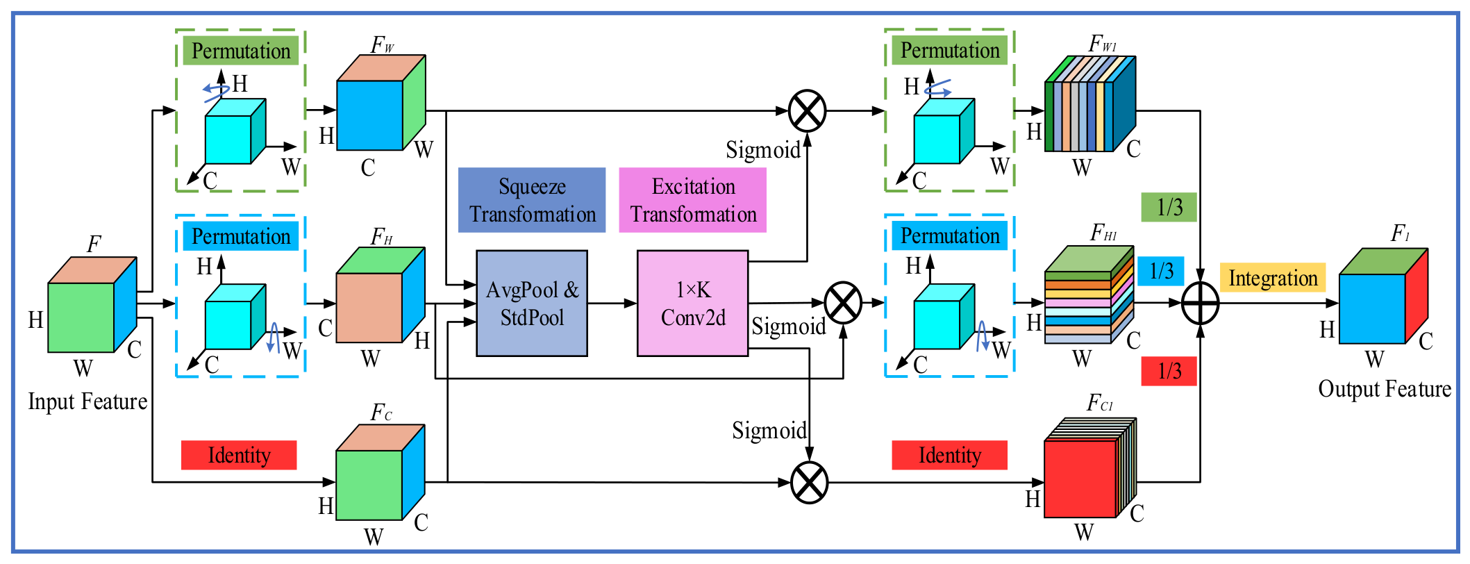
In order to enhance the ability in capture surface defect features in small irregular stamped parts, a Multidimensional Collaborative Attention (MCA) module [24] is incorporated into YOLOv8. This module uses residual transformations and rotation operations to create inter-dimensional relationships, enabling efficient information interaction and fusion across three dimensions. By enhancing the emphasis on critical surface defect features, the MCA module significantly improves the model’s detection performance, particularly for small irregular parts. As depicted in Figure 5, The three parallel branches of the MCA module enable efficient integration of spatial and feature-channel information, while also reducing the computational burden associated with spatial dimensions. The feature map FRC×H×W is processed through these three branches, allowing for more precise extraction of critical features.
First Branch: The input feature map F is first subjected to a 90° counterclockwise rotation along the height (H) axis, resulting in a transformed feature map, denoted as FWRW×H×C then Squeeze, Excitation, and Sigmoid activation are the transformations that are applied to produce the feature weights along the width direction. The Squeeze operation integrates features extracted through both mean and standard deviation pooling, effectively aggregating input feature information to enhance interaction and improve the comprehensiveness of the output features. The Excitation operation dynamically adjusts the interaction range, enabling the capture of localized feature information across channels. Finally, the width feature weights are multiplied with the original feature map F, then rotated in a clockwise direction to create a feature map FW1RC×H×W with enriched information. The definition of this operation is given by Equation (1):
F W 1 = P M H 1 σ T e x T s q P M H F P M H F
Second Branch: The input feature map F is rotated counterclockwise to obtain the feature map FHRH×C×W. FH is then sequentially passed through the Squeeze, Excitation, and Sigmoid activation functions. After the feature map is enhanced, it is rotated clockwise to obtain a feature map FH1RC×H×W, which matches the initial input shape. This operation is defined as shown in Equation (2):
F H 1 = P M W 1 σ T e x T s q P M W F P M W F
Third Branch: The input feature map F is passed through an identity mapping to generate a feature map FCRC×H×W, such that FC = F. FC is then sequentially processed through the Squeeze, Excitation, and Sigmoid activation functions to obtain specific channel attention weights. The output feature map FC1RC×H×W with enriched information is obtained by performing a multiplication operation between the feature map FC and the channel attention weights, followed by a secondary identity mapping. This operation is defined as shown in Equation (3):
F C 1 = I M σ T e x T s q I M F I M F
Equations (1)–(3) define the following operations: PMH(●) represents a counterclockwise rotation by 90° along the height (H) axis, while P M H 1 corresponds to a clockwise rotation by 90° along the height (H) axis. Similarly, PMW(●) denotes a counterclockwise rotation by 0° along the width (W) axis, and P M W 1 refers to a clockwise rotation by 90° along the width (W) axis. The function σ(●) represents the Sigmoid activation function, while Tsq(●) and Tex(●) correspond to the Squeeze and Excitation operations, respectively. IM(●) denotes the identity mapping function. The rotation operations can be implemented using the Permutation operation in Python.
Lastly, deeper feature information can be recovered across channels by averaging and combining the output attention weights produced by the three branches across several dimensions, resulting in more precise target localisation and recognition. The final feature map F1, enriched with semantic information, is derived from the augmented feature maps FW1, FH1, and FC1, as shown in Equation (4):
F 1 = 1 3 F W 1 F H 1 F C 1
In this study, MCA is used as an attention-enhancement component rather than as an independent detection framework. Based on cross-dimensional information exchange, MCA strengthens the interaction between spatial and channel information, enabling the network to focus more effectively on weak and small defect regions without increasing the number of model parameters. This is suitable for small irregular stamped-part defect detection because small-object prediction boxes often contain a relatively large proportion of background information. By enhancing attention to defect-related regions, the network can better distinguish true surface defects from metallic reflection and background interference.

2.3.3. C2f-CRM Module

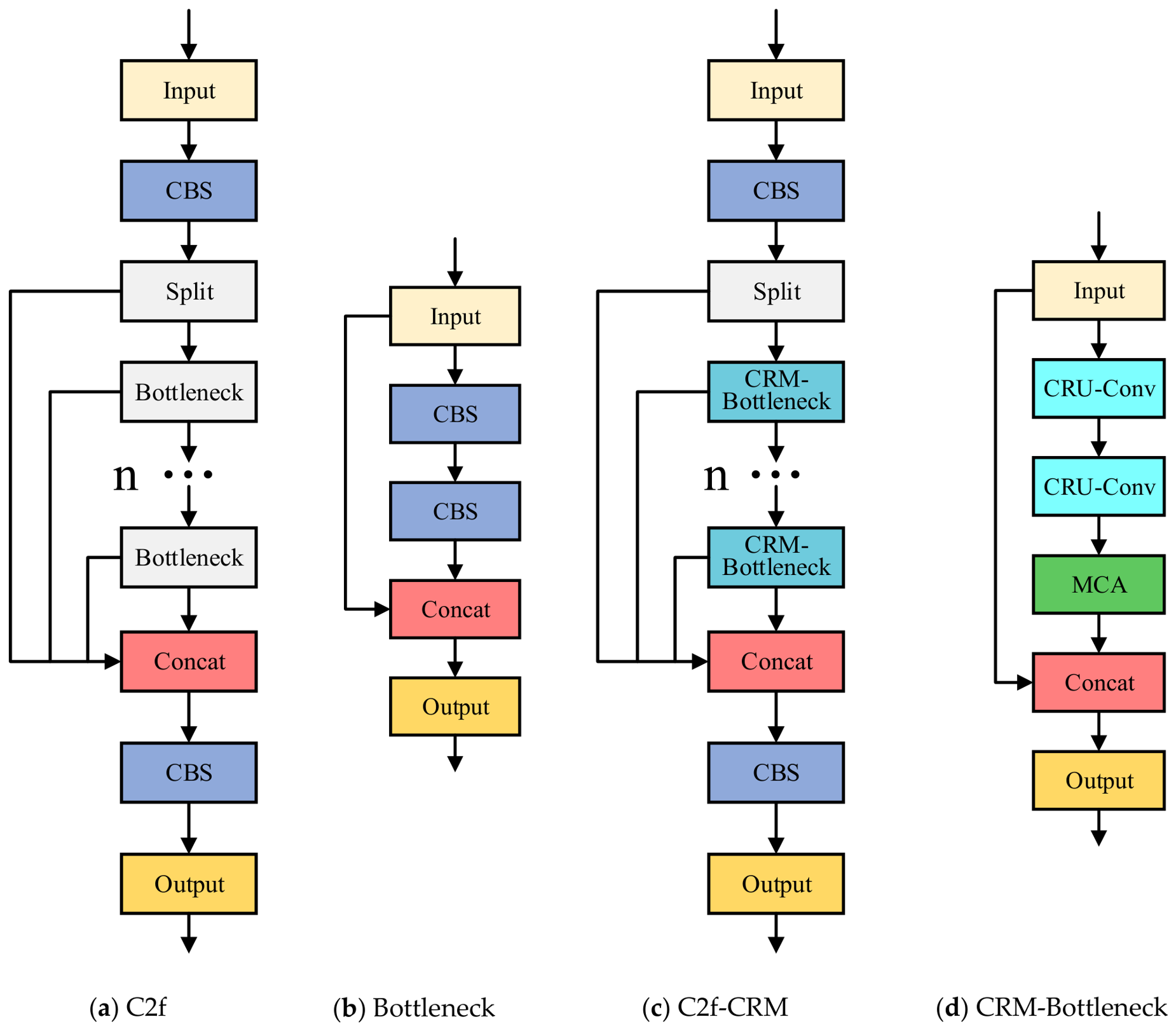
The C2f module of YOLOv8 primarily utilizes conventional convolutions for feature extraction from the input feature map, as illustrated in Figure 6a. However, the extensive stacking of convolutional layers often leads to a significant redundant data, increasing the computational burden of the model. This redundancy may also result in missed or false detection of small surface defects in small irregular stamped parts. To address these issues, this study incorporates Channel Reconstruction Unit Convolution (CRU-Conv) [25] and the MCA module to design the C2f-CRM module, as presented in Figure 6c. The improved C2f module effectively reduces computational resource consumption and increases the ability of the network to extract features, enabling the model to better capture rich contextual information. This module is capable of extracting detailed regions of interest in complex backgrounds, thereby improving the algorithm’s classification and recognition performance. By introducing the CRM-Bottleneck within the C2f module, as demonstrated in Figure 6d, network’s capability to process fine-grained features is enhanced, while also become more sensitive to recognition and detection of small targets.
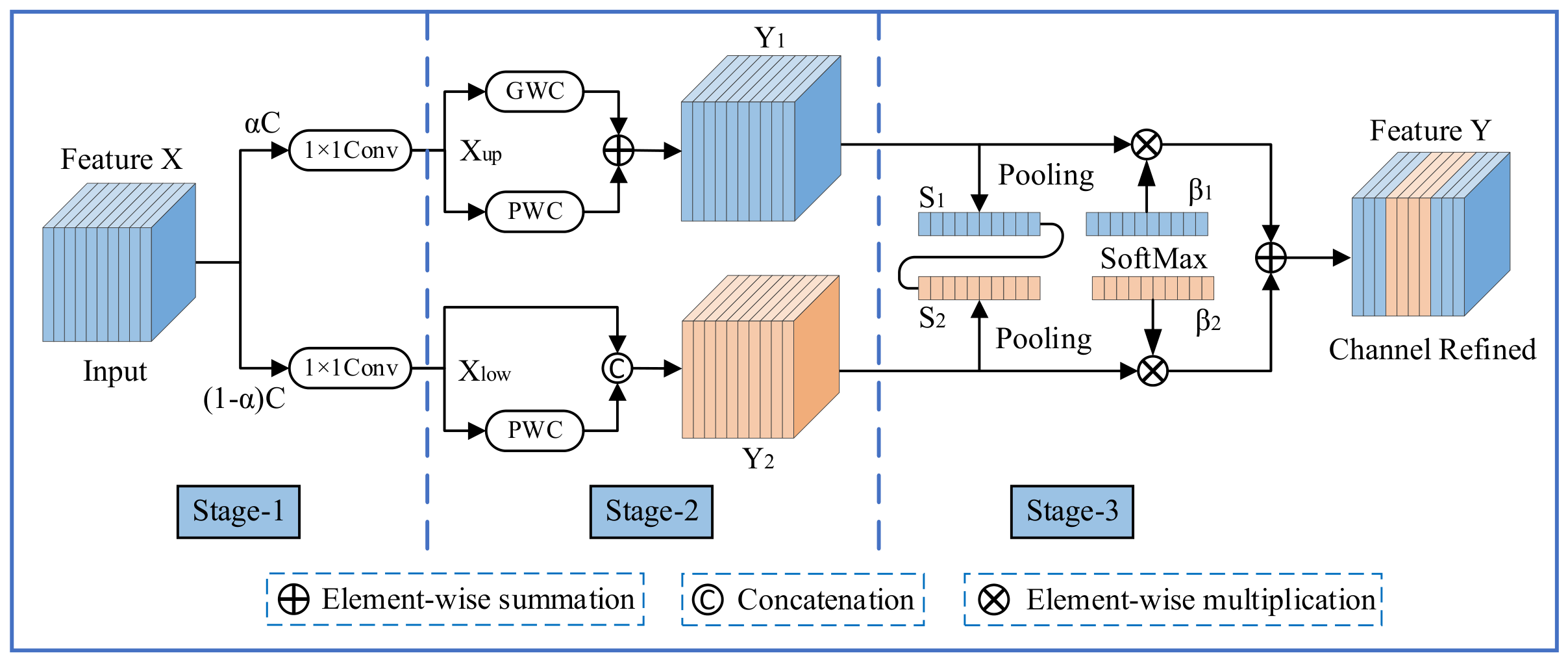
By incorporating the CRU-Conv module, the channel redundancy between features is reduced, allowing the model to more effectively handle variations in object scale, rotation, and other factors. As shown in Figure 7, CRU-Conv consists of three steps: segmentation, transformation, and fusion. Here, MKRC×K×K represents the K × K convolution kernel, X and YRC×H×W denote the input and output features, respectively. The convolution operation is defined as Y = MkX. To fully extract defect features from the surface of small irregular stamped parts, CRU-Conv is employed to replace the standard convolution in the Bottleneck layer of the C2f module. The convolution module significantly decrease information loss during downsampling process.
Stage-1: The input feature map X is divided into two parts: αC channels and (1 − α)C channels, as shown in Stage-1 of Figure 7, where 0 ≤ α ≤ 1 represents the partition ratio. By applying a 1 × 1 convolution to compress the feature channels, the number of model parameters is effectively reduced. After the partitioning and compression operations, the feature map X is split into Xup and Xlow.
Stage-2: The feature map Xup is fed into the upper transformation stage. By employing efficient convolutional operation combinations to replace traditional convolutions, deep semantic information is effectively extracted, resulting in a rich feature map Y1 with lower computational cost. Meanwhile, Xlow is input into the lower transformation stage to generate a feature map with shallow semantic information. Through pointwise convolution (PWC) operations and feature reuse strategies, the lower branch produces a feature map Y2 containing detailed supplementary information. Y1 and Y2 are defined in Equations (5) and (6), where M G R α C g r × K × K × C , M P 1 R α C r × 1 × 1 × C , and M P 2 R 1 α C r × 1 × 1 × 1 1 α r are as follows.
Y 1 = M G X u p + M p 1 X u p
Y 2 = M p 2 X l o w X l o w
Stage-3: After the transformation in the previous step, the simplified SKNet method [26] is employed to adaptively merge the output feature maps, as shown in Stage-3 of Figure 7. Global feature information SmRC×1×1 is gathered using global average pooling. The global features from the upper and lower branches, S1 and S2, are then stacked together, and a SoftMax operation to produce the feature vectors β1 and β2. Finally, the two feature maps, Y1 and Y2, each containing different informational features, are merged along the channel dimension, enhancing the information flow and resulting in a channel-refined feature map Y, as defined in Equation (7).
Y = β 1 Y 1 + β 2 Y 2
The improved C2f-CRM module reduces feature redundancy and facilitates cross-channel information flow through a three-step strategy of splitting, transforming, and merging via the CRU-Conv module. Additionally, the MCA module improves the model’s detection accuracy and efficiency by facilitating parallel learning in both the spatial and channel dimensions. The C2f-CRM module is capable of simultaneously capturing the positional information emphasized by shallow features and the semantic information highlighted by deep features, enhancing the model’s capacity to extract features and gather more thorough contextual data. Therefore, the role of C2f-CRM in YOLO-CGMS is to provide an efficient feature extraction structure for small-defect representation, rather than simply increasing the depth or complexity of the network.

2.3.4. Global Receptive Field-Space Pooling Pyramid Fast Module

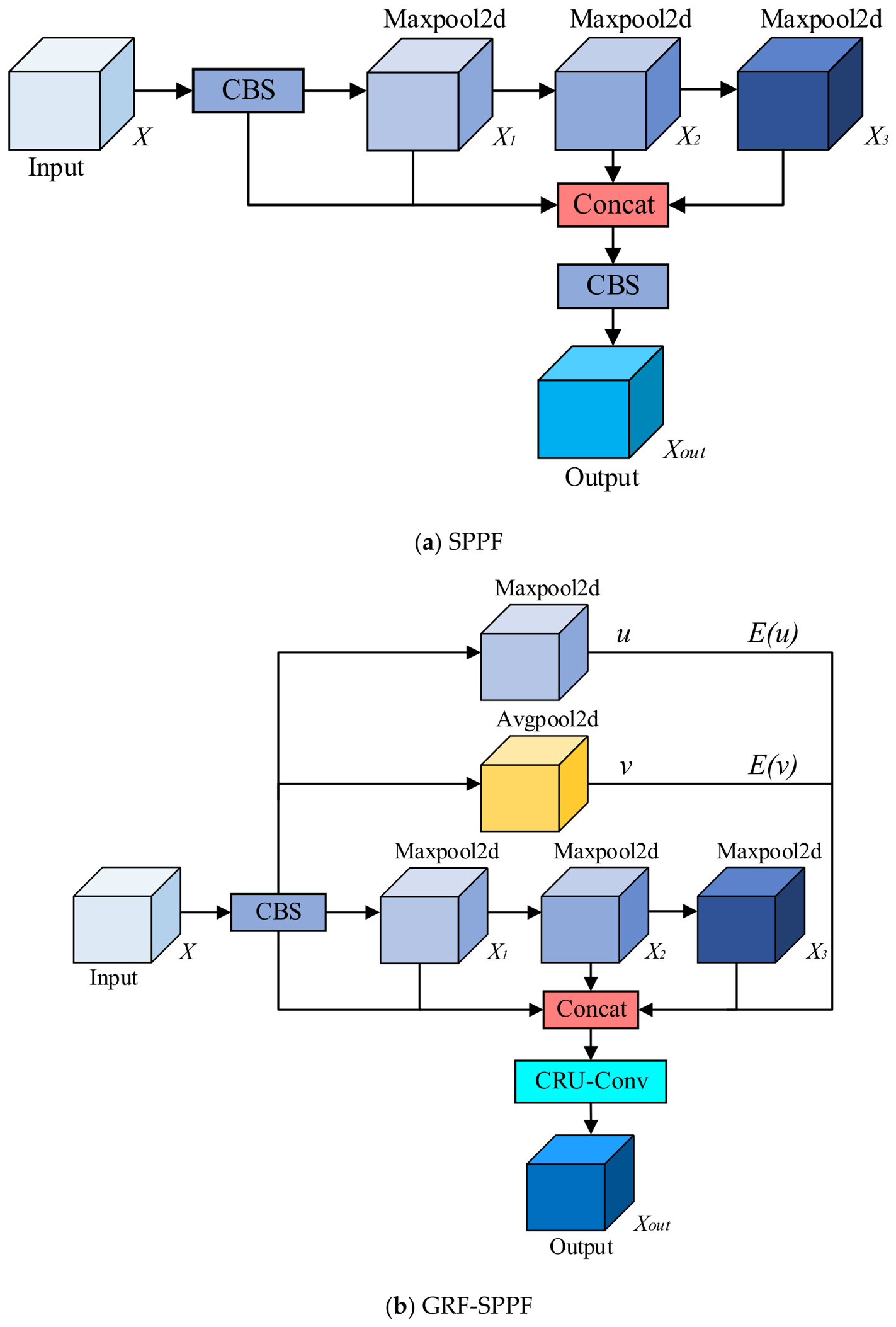
Due to the small size of surface defects on irregular stamped parts, the number of defect pixels in the image is limited, which makes it difficult for the network to extract and localize discriminative defect features. The SPPF module in YOLOv8 mainly extracts multi-scale information through three max-pooling layers. However, relying only on max pooling may lead to insufficient use of global contextual information, especially when defect regions are disturbed by metallic reflection, edge texture, or background interference. To address this problem, a Global Receptive Field-Space Pooling Pyramid Fast (GRF-SPPF) module is designed based on the original SPPF structure. As shown in Figure 8, GRF-SPPF adds two pooling branches to the original max-pooling path and uses CRU-Conv for feature fusion. This design strengthens the integration of local receptive-field information and global contextual information while maintaining a lightweight structure.
The GRF-SPPF module changes the capability to process intricate and nuanced features by integrating global average pooling and global max pooling layers, which are used to extract global background and edge information. The input feature layer of the GRF-SPPF module is divided into three distinct paths. The primary path employs three max-pooling layers to generate feature maps X1, X2, and X3, capturing key local information. The other two paths use global average pooling and global max pooling to produce feature maps u and v, representing global background and prominent global features, respectively. These feature maps are concatenated through the Concat operation. Finally, the CRU-Conv convolution is applied to integrate the channels and extract features, resulting in the output feature map Xout, as expressed in Equation (8).
X o u t = f C X 1 , X 2 , X 3 , E u , E v , X
In Equation (8), E(v) and E(u) represent the feature layers expanded to match the dimensions of the input features through an exponential transformation, the function C denotes the dimensional concatenation of these feature layers along both the width and height directions. By leveraging feature information from different receptive fields, the network’s capacity to extract fine-grained features and express nonlinear characteristics is enhanced, effectively capturing feature information across various scales and levels. This module efficiently integrates both local and global receptive fields while maintaining computational efficiency, thereby reducing the adverse effects of scale variations. Thus, GRF-SPPF is mainly responsible for improving contextual feature representation in YOLO-CGMS, helping the model distinguish small defect regions from non-defective metallic textures and background noise.

2.3.5. Inner-GIoU Loss Function

In the surface defect detection of small irregularly shaped stamping parts, the compact size of the stamping parts often leads to the occurrence of multiple small defect targets in close proximity. When the bounding boxes of these small targets in aggregated regions are spaced too closely, it becomes challenging for the model to regress these bounding boxes accurately, hindering convergence. YOLOv8 utilizes CIoU Loss to compute the bounding box regression loss. While CIoU Loss effectively captures the regression state of bounding boxes, it lacks the capability to adaptively adjust for different detection targets, and does not exhibit strong judgment and generalization abilities, which presents certain limitations. The formula is given in Equation (9), where IoU represents the Intersection over Union, ρ(●) denotes the Euclidean distance between the centers of the predicted and ground truth boxes, c denotes the length of the diagonal of the smallest outer rectangle that encloses the true frame and the prediction, v is the parameter that measures the aspect ratio consistency, and α is the balance factor.
L C I o U = 1 I o U + ρ 2 b , b g t c 2 + α v
The equations for v and α are given in (10) and (11), where ω(gt), h(gt), ω, and h represent the width and height of the ground truth and predicted bounding boxes, respectively.
v 2 = 4 π 2 arctan ω g t h g t arctan ω h 2
α = v 1 I o U + v
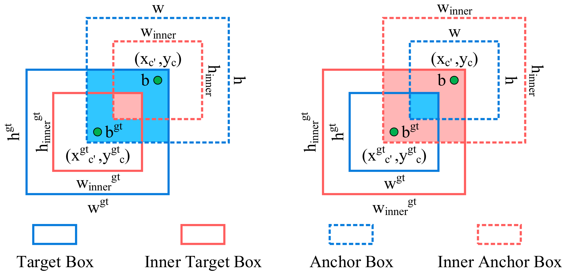
To improve the precision of tiny target detection in dense scenes, this research introduces the Inner-IoU [27] method, which incorporates auxiliary bounding boxes as illustrated in Figure 9. By integrating Inner-IoU with GIoU [28], the concept of Inner-GIoU is proposed. Unlike CIoU, this method concentrates more on the bounding box’s central areas. allowing for a more precise assessment of overlapping areas. Furthermore, Inner-GIoU utilizes bounding boxes at various scales for loss calculation, enhancing the efficiency of bounding box regression and accelerating model convergence. This method proves particularly effective for detecting small objects in dense scenes.
The calculation formula for the Inner-GIoU loss function is given in Equation (12).
L i n n e r - G I o U = 1 I o U i n n e r + c B B g t c 2
Here, B and B(gt) denote the predicted and ground truth bounding boxes, respectively, while c denotes the smallest outer rectangle enclosing the prediction box and the true box. IoUinner refers to the Inner-IoU, and its specific calculation is as follows:
b 1 = x c w r 2 b 2 = x c + w r 2 b 3 = y c h r 2 b 4 = y c + h r 2
The variables xc and yc denote the coordinates of the center of the predicted bounding box, where the subscript c indicates the center. The height and width of the predicted bounding box are represented by h and w, respectively. The scale factor r ∈ [0.5, 1.5] controls the size of the auxiliary bounding boxes. Specifically, b1 and b2 refer to the x-coordinates of the left and right boundaries of the predicted bounding box, while b3 and b4 represent the y-coordinates of the top and bottom boundaries. Here, the subscripts 1 and 2 correspond to the left and right boundaries, and 3 and 4 correspond to the top and bottom boundaries.
i = m i n ( b 2 g t , b 2 ) m a x ( b 1 g t , b 1 m i n ( b 4 b t , b 4 ) m a x ( b 3 g t , b 3 )
In Equation (14), b 1 g t   b 2 g t , b 3 g t and b 4 g t represent the x-coordinates of the left and right boundaries and the y-coordinates of the top and bottom boundaries of the ground-truth bounding box, respectively. The variable i denotes the intersection area between the auxiliary predicted bounding box and the auxiliary ground-truth bounding box.
u = w g t h g t r 2 + w h r 2 i
In Equation (15), gt represents the ground-truth bounding box, with h(gt) and w(gt) representing its height and width, respectively. The variable u refers to the union area of the auxiliary predicted bounding box and the auxiliary ground-truth bounding box.
I o U i n n e r = i u
In YOLO-CGMS, Inner-GIoU is therefore used as a regression-optimization strategy for small and densely distributed defect targets, complementing the feature-enhancement modules described above.

2.4. Camera-to-Robot Coordinate Mapping and Dynamic Sorting Strategy

To enable the detected defect position to guide robotic sorting, a coordinate mapping relationship was established among the industrial camera, conveyor, and Delta robot. After the YOLO-CGMS module detects a defective workpiece, the output pixel coordinate is first converted into the physical coordinate on the conveyor plane. In this process, the pixel coordinate of the detected target, the pixel coordinate of the conveyor world-coordinate origin, and the pixel-to-physical scaling factors in the X and Y directions are used to obtain the target position in the conveyor world coordinate system. The calibration relationship among the image coordinate system, conveyor world coordinate system, and Delta robot coordinate system is shown in Figure 10.
During system installation, the X-axis direction of the Delta robot coordinate system was kept parallel to the X-axis direction of the conveyor world coordinate system. Based on the relative distance between the origin of the conveyor world coordinate system and the origin of the Delta robot coordinate system, the target position in the conveyor coordinate system was further transformed into the Delta robot base coordinate system. Therefore, the visual detection result could be converted into the target position required for robotic sorting.
Because the stamped part continues to move on the conveyor after image acquisition, the sorting position must be determined according to the mapped target coordinate and the conveyor motion state. When the converted target coordinate falls within the effective working range of the Delta robot, the system generates the corresponding sorting command. The Delta robot then moves to the target position and uses the pneumatic suction end-effector to pick up the defective workpiece.
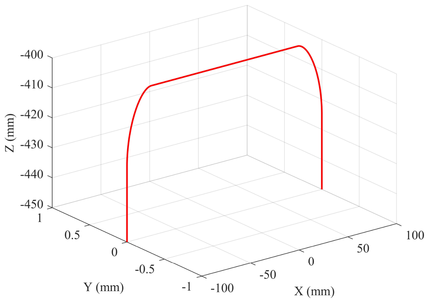
For the pick-and-place task, an improved gate-shaped trajectory was adopted. This trajectory allows the end-effector to move from the standby position to the picking position, lift the workpiece, transfer it to the collection area, and then return to the standby position. To reduce the impact caused by rapid acceleration and deceleration during dynamic sorting, a modified trapezoidal acceleration–deceleration strategy was used for motion planning. The improved gate-shaped trajectory used for suction-based pick-and-place sorting is shown in Figure 11. This strategy improves motion smoothness and helps ensure stable suction-based sorting of small irregular stamped parts.

2.5. Prototype Platform and Control Procedure

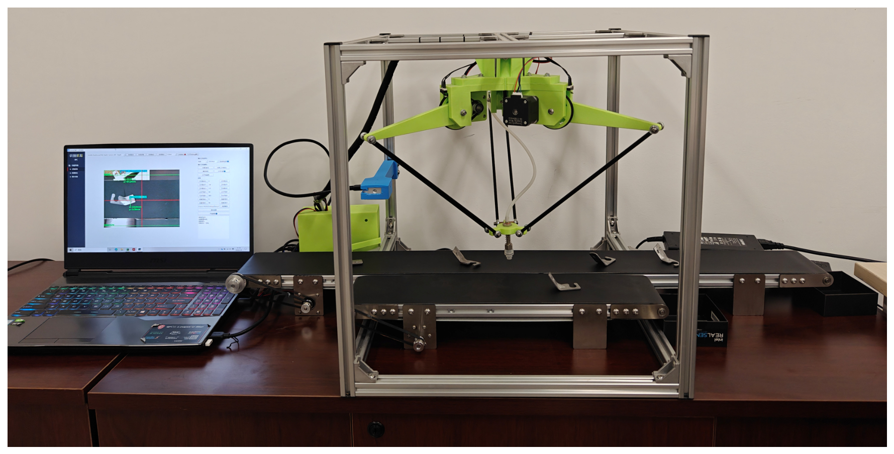
According to the testing requirements, a prototype surface defect detection system for small irregular stamped parts based on a Delta robot was successfully developed, as shown in Figure 12. The prototype mainly consists of a conveyor transport unit, a machine vision recognition unit, a Delta robot sorting unit, a control cabinet, a suction device, and collection bins. To enable efficient quality inspection and suction-based pick-and-place operations for small irregular stamped parts on the conveyor, an eye-to-hand configuration was adopted for the industrial camera. Specifically, the camera was fixed above the conveyor outside the operating area of the robot and connected to a laptop via a USB interface, enabling real-time acquisition, transmission, and processing of workpiece images.
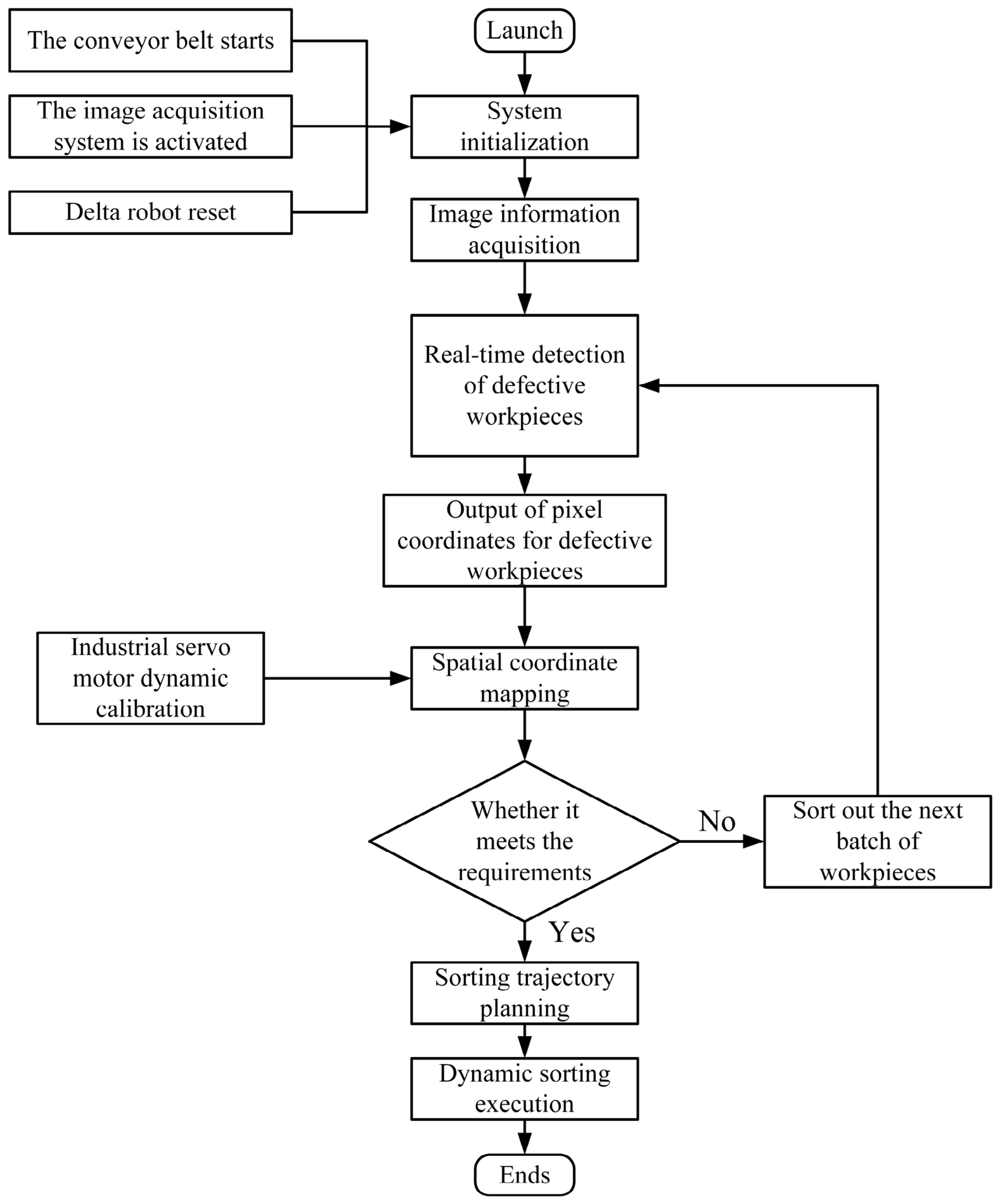
After the platform for detecting defective small irregular stamped parts was established, an overall control scheme was designed according to its actual operational logic, as shown in Figure 13. The specific execution procedure is described as follows:
(1)
System initialization: During system power-on and initialization, the conveyor belt is started first. The industrial camera then begins operation, capturing images of the stamped parts on the conveyor in real time and transmitting them to the laptop. Simultaneously, the microcontroller sends a command to the Delta robot to perform a homing operation, ensuring that the robot is in a standby state.
(2)
Image acquisition: After initialization, the vision acquisition system operates continuously to capture images of the small irregular stamped parts on the conveyor and transmit them to the laptop in real time.
(3)
Real-time dynamic surface defect detection: The developed YOLO-CGMS dynamic detection model is employed to identify surface defects in small irregular stamped parts moving along the conveyor in real time.
(4)
Output of pixel coordinates of defective workpieces: Once a defective workpiece is identified during dynamic detection, the system immediately calculates and outputs its pixel coordinate information in the image.
(5)
Spatial coordinate mapping: Based on the previously established dynamic calibration method for the industrial camera, the pixel coordinates of the defective workpiece are accurately transformed into position coordinates in the coordinate system of the Delta robot.
(6)
Sorting decision: The transformed position information is evaluated on the laptop using the developed dynamic sorting model. When the coordinate data satisfy the requirements for sorting, the corresponding motion parameters are calculated and transmitted to the microcontroller via serial communication. Otherwise, the workpiece is disregarded, and the system automatically proceeds to the next detection cycle.
(7)
Sorting trajectory planning: Based on the received target position information, the sorting actuator plans an appropriate pick-and-place trajectory for the Delta robot according to the predefined gate-shaped motion path.
(8)
Dynamic sorting execution: The microcontroller drives the Delta robot along the planned trajectory to accurately sort defective small irregular stamped parts while the conveyor belt remains in continuous operation.

3. Results

3.1. Experimental Environment

The experimental environment is conFig.d with an NVIDIA L20 GPU featuring 48 GB of VRAM and an Intel Xeon Platinum 8457C CPU operating at 3.0 GHz for computation. Code development, training, and testing were carried out a Windows operating system. Python (version 3.10.14) was used for programming, the PyTorch is version 1.13.0, which employed for model construction. Model training acceleration was achieved through the use of CUDA 11.7 and cuDNN 8.5.0, maintaining uniformity in the hardware and software environments.
For the training parameter settings, the input image resolution is 960 × 720, with 400 epochs, a batch size of 16, an initial learning rate of 0.01, momentum set to 0.937, and weight decay of 0.0005. The model optimization is performed using the SGD optimizer. In the image augmentation process for each batch, the following transformations are applied with corresponding probabilities: translation perturbation (0.1), mosaic augmentation (1.0), random brightness adjustment (0.4), and random saturation adjustment (0.7). To ensure a fair comparison, all models involved in the ablation and comparative experiments were trained and evaluated using the same dataset division, hardware platform, software environment, input image size, optimizer, and training parameter settings. These augmentations are aimed at expanding the training dataset and enhancing the model’s generalization capacity.

3.2. Experimental Datasets

The datasets employed in this study was sourced from Chengdu Juxin Machinery Equipment Co., Ltd., based on their designed data collection scheme. Images of small irregular stamped parts were selected for the dataset. A total of five industrial cameras (IV3-G500CA) were used for image acquisition on the detection line for small irregular stamped parts. Each image has a size of 129 KB and a resolution of 1280 × 960 pixels. The detection line processes approximately 8000 small irregular stamped parts daily, with around 90 images captured per part. Therefore, approximately 720,000 images of small irregular stamped parts are collected daily.
From the images collected on the detection line, 2200 images containing edge defects, pits, oil stains, hole misalignment, and scratches, as well as 1000 defect-free images, were selected to construct the dataset for surface defects of small irregular stamped parts. The selection of these 3200 images was based on both image quality and sample representativeness. Images with severe motion blur, overexposure, incomplete workpieces, unclear defect boundaries, strong reflection fully covering the defect region, and repeated near-identical consecutive frames were removed. The retained images were selected to cover different defect categories, workpiece orientations, imaging angles, and metallic reflection conditions as much as possible. After image selection, the defect categories and bounding boxes were manually checked to ensure that the annotations correctly described the visible defect regions. The dataset was split into training, validation, and testing sets in a ratio of 8:1:1, as detailed in Table 1.

3.3. Experimental Indicators

To effectively and intuitively present the improvements of this study on YOLOv8, performance metrics including Precision, Recall, and mean Average Precision (mAP50) were employed. Model evaluation metrics such as the number of model parameters (Params), model computational complexity (GFLOPS), and detection speed (FPS) were also used. The corresponding formulas are as follows:
P = T P T P + F P
R = T P T P + F N
A P = 0 1 P ( R ) dR
m A P = 1 n i = 0 n A P ( i )
In this context, TP denotes the number of instances where a predicted target is actually a correct target, FP indicates the number of instances where a predicted target is not a correct target, FN represents the number of instances where a non-target is predicted as a target but is actually a target. AP refers to the accuracy for each detection type, while mAP represents the mean average precision across all categories, where n denotes the total number of categories. In addition to the model-level metrics, positioning error, sorting success rate, and average processing time per workpiece were used to evaluate the prototype detection and sorting system.

3.4. YOLOv8 Model Selection

The YOLOv8 model includes five versions: YOLOv8n, YOLOv8s, YOLOv8m, YOLOv8l, and YOLOv8x. Although the network architecture used in these versions is the same, they differ significantly in terms of network depth, feature map width, number of parameters, and computational complexity. For example, YOLOv8x has 68.1 M parameters, whereas YOLOv8n has only 3.0 M parameters. Despite the identical architecture, the input image size has a significant impact on inference speed (FPS) and computational load (GFLOPS). In this study, the original image size in the dataset was 1280 × 960 pixels, which was resized to 960 × 720 pixels and 720 × 540 pixels as required. The model’s performance was evaluated at different input sizes, with results detailed in Table 2.
As shown in Table 2, under the same network architecture, reducing the input image size from 1280 × 960 pixels to 960 × 720 pixels resulted in improvements in both mAP50 and FPS, while GFLOPS significantly decreased. This suggests that reducing input size can enhance inference speed and reduce computational load to some extent. However, when the image size was further reduced to 720 × 540 pixels, both mAP50 and GFLOPS declined, indicating that the loss of image details negatively impacted detection performance. Specifically, when the input image size was 960 × 720 pixels, the YOLOv8n is the best, with an mAP50 of 83.6%, an FPS of 224.05 frames/s, 3.0 M parameters, and 8.1G GFLOPS. These experimental results indicate that while increasing network depth and feature map width improves the model’s representational capacity, it does not significantly enhance detection accuracy. Therefore, considering the real-time defect detection requirements for small irregular stamped parts—where detection speed is crucial—this study ultimately chose 960 × 720 pixels as the input image size and selected YOLOv8n as the base network model.

3.5. Comparison of Attention Modules

To more clearly demonstrate how the MCA mechanism improves model performance, this experiment selected the same dataset of surface defects on small irregular stamped parts. The CBAM [29], SA [30], SRM [31], ECA [32], SimAM [33], and MCA attention mechanisms were individually integrated into the YOLOv8n network model for comparative testing. The results, summarized in Table 3, demonstrate the distinct impact of each attention mechanism on model performance. Among them, the MCA attention mechanism demonstrated the most significant improvement in model performance, with an increase of 2.2% in mAP50. This underscores the advantages of the MCA attention mechanism in emphasizing surface defect features of small irregular stamped parts across both channel and spatial dimensions, further confirming its efficiency in enhancing the recognition of critical features.

3.6. Loss Function Experiment

To show the Inner-GIoU loss function in detecting tiny objects, we integrated this loss function into the YOLO-CGMS model and conducted a series of 11 comparative experiments by adjusting different Ratio values within a range of [0.5, 1.5]. The experimental results are presented in Table 4.
By analyzing the model’s performance under varying Ratio values, it is clear that the Params and GFLOPS remain constant, while detection accuracy for small objects is significantly influenced by the Ratio. Specifically, the optimal performance is achieved with a Ratio of 0.9, resulting in a precision of 80.6%, recall of 99.7%, mAP50 of 88.7%, and a frame rate of 236.23 frames per second. These results demonstrate that combining the Inner-IoU and GIoU loss functions, based on auxiliary bounding boxes, successfully tackles the difficulties of small object detection tasks. This approach is particularly advantageous in dense scenarios, where it significantly enhances the model’s accuracy and overall performance in detecting small objects.

3.7. Ablation Experiments

To evaluate the optimization effects of various modules in the YOLOv8n model, an ablation study was conducted on the dataset of surface defects from small irregular stamped parts. Table 5 presents the experimental results, where “√” indicates the inclusion of a specific improvement and “×” denotes its absence. As shown in Table 5, introducing the MCA mechanism alone resulted in a 2.2% increase in mAP50 without affecting the number of parameters. Replacing the C2f module in the YOLOv8n model with C2f-CRM led to a 2.7% increase in mAP50, a reduction of 0.4 M parameters, and a 0.9G decrease in computational load. Incorporating the GRF-SPPF module further improved the mAP50 by 1.8%, with a minor increase of 0.1M in parameters. The integration of the Inner-GIoU loss function achieved a 1.6% improvement in mAP50 while keeping the parameter count and computational load unchanged. Adding the CM-Bottleneck module to the C2f-CRM facilitated more efficient information exchange, improving the model’s feature extraction capability. Meanwhile, the Inner-GIoU loss function improved small object detection across multiple scales. These enhancements reduced redundant computations and model complexity.
By integrating the MCA, C2f-CRM, and GRF-SPPF modules, the YOLOv8n model achieved a 3.9% increase in mAP50, accompanied by a reduction of 0.2 M parameters and a 0.8G decrease in computational load. This suggests that the model achieves a bigger receptive field and enhanced small item identification capacity after extracting deeper information. Under the premise of reducing parameter count and computational complexity, both detection accuracy and speed were significantly enhanced. In summary, compared to the YOLOv8n model, the proposed YOLO-CGMS model demonstrated substantial improvements in detecting surface defects on small irregular stamped parts while reducing parameters and computational load. These findings support the viability and efficacy of the study’s suggested enhancements.
The ablation results further explain the contribution of each component in YOLO-CGMS. MCA mainly improves the model’s ability to focus on weak and small defect regions, which contributes to the improvement of detection accuracy. C2f-CRM reduces redundant channel information and improves feature extraction efficiency, which helps maintain a lightweight model structure. GRF-SPPF enhances the receptive-field representation and improves the use of contextual information, making the model more robust to metallic reflection and background interference. Inner-GIoU improves the localization accuracy of small and dense defect targets by optimizing the bounding-box regression process. These modules play different roles in the network, and their combination enables YOLO-CGMS to achieve a more suitable balance between accuracy and real-time performance for the stamped-part inspection task.

3.8. Comparison with the YOLOv8n Model

To verify the improvements in detection performance achieved by the YOLO-CGMS model, YOLO-CGMS and the YOLOv8n model were compared in an experiment. Table 6 compares various metrics, including accuracy, recall, mAP50, FPS, model parameters, and computational load, based on training with the dataset used in this study. As shown in the table, the YOLO-CGMS model achieved a 4.5% increase in accuracy, a 5.1% improvement in mAP50, and a 12.18 frames/s boost in FPS. Moreover, the YOLO-CGMS model decreased the computational load and number of parameters by 0.8G and 0.2M, respectively. The results shows YOLO-CGMS improves the accuracy of detecting surface defects on small irregular stamped parts and significantly strengthen detection ability, making it more suited for the detection requirements of real-world production environments.
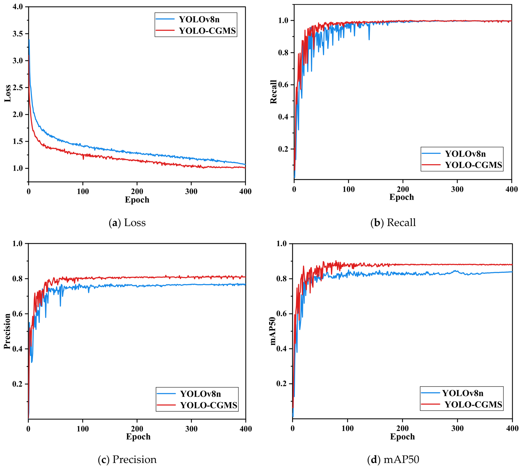
Figure 14 illustrates a comparison of the loss, recall, precision, and mAP50 trends during training for the YOLOv8n and YOLO-CGMS models. From the loss function curve, it can be observed that the YOLO-CGMS model achieved a lower loss value after training, indicating that the improvements to the loss function effectively enhanced the model’s convergence speed and stability. When comparing precision, recall, and mAP50 curves, the YOLO-CGMS model consistently outperformed the YOLOv8n model across all metrics. These findings imply that, in comparison to YOLOv8n, the YOLO-CGMS model not only converges more quickly but also exhibits better accuracy and overall performance.
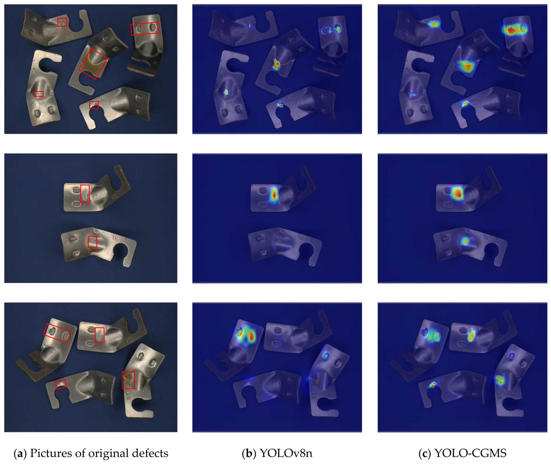
In this study, a visual comparison of the feature extraction capabilities of the YOLOv8n and YOLO-CGMS models was conducted using Gradient-weighted Class Activation Mapping (Grad-CAM) [34]. Grad-CAM provides a clear and intuitive visualization of the regions that the model focuses on when processing an image. Figure 15 shows that for various surface defect types on workpieces, When compared to the YOLOv8n model, the YOLO-CGMS model shows noticeably greater attention to both big and small target areas. In summary, the YOLO-CGMS model more effectively focuses on the surface defects of workpieces. Consequently, the model’s ability to extract features is improved and bounding box predictions are more accurate.

3.9. Comparison with Other Mainstream Algorithms

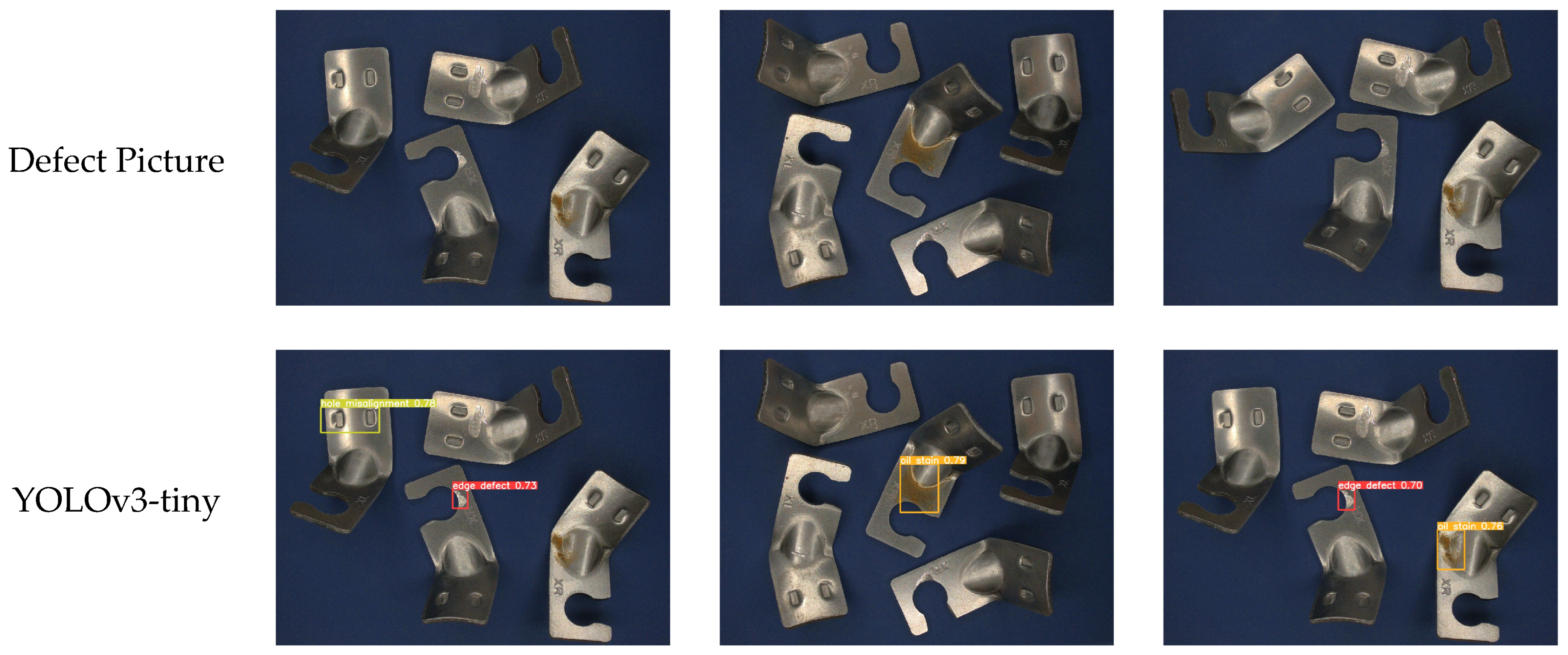
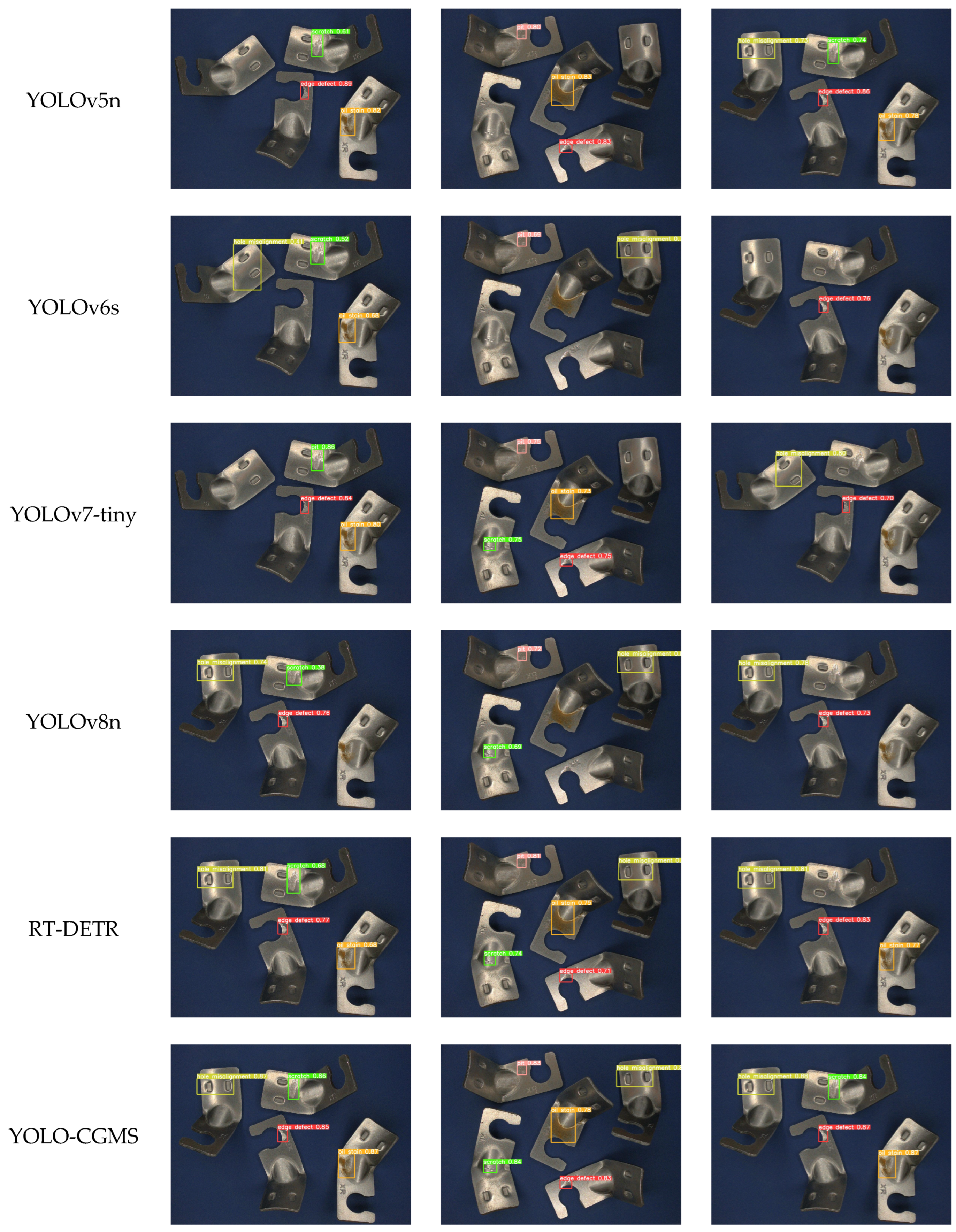
To thoroughly assess the enhancements introduced to the YOLOv8n model in this investigation, a comparison is conducted between the modified YOLOv8n model and several other models. The comparison takes into account both the most recent models created by well-known businesses and research groups as well as traditional models created prior to YOLOv8, such as YOLOv3-tiny [35], YOLOv5n [36], YOLOv6s [37], YOLOv7-tiny [38], YOLOv8n, and RT-DETR [39]. In total, seven sets of comparative experiments were performed using the same hardware, environment, and dataset. Table 7 presents the results of these comparisons.
As observed in Table 7, the YOLO-CGMS model outperforms the YOLOv3-tiny, YOLOv5n, YOLOv6s, YOLOv7-tiny, and YOLOv8n models in terms of detection accuracy, speed, model parameters, and computational load. Specifically, compared to YOLOv3-tiny, the YOLO-CGMS model achieved a 13.3% improvement in mAP50 and a 39.74 frames/s increase in FPS. When compared to YOLOv5n, mAP50 increased by 6.4%, and FPS improved by 19.55 frames/s. Compared to YOLOv6s, mAP50 rose by 6.8%, and FPS increased by 51.47 frames/s. With respect to YOLOv7-tiny, mAP50 improved by 6.5%, and FPS increased by 17.71 frames/s. Compared to baseline, the proposed model showed about 5.1% increase in mAP50 and 12.18 frames/s improvement in FPS. Therefore, although YOLO-CGMS did not obtain the highest mAP50 among all compared models, it provided more suitable overall performance for the proposed vision-based dynamic defect detection and robotic sorting system. The high inference speed and lightweight structure make it more appropriate for continuous image acquisition, real-time defect recognition, and subsequent coordinate mapping and robotic sorting.
Figure 16 presents the visual comparison of different models in the defect detection task. The results show that YOLO-CGMS can correctly locate the main defect regions and maintain high confidence under complex defect appearances. Although RT-DETR achieved a slightly higher mAP50 in Table 7, it required substantially more parameters and computational cost and showed a much lower inference speed. In contrast, YOLO-CGMS achieved a more balanced performance, with an mAP50 of 88.7%, an FPS of 236.23 frames/s, 2.8 M parameters, and 7.3 GFLOPs. This balance is important for the proposed system because the detection model must provide real-time outputs for subsequent coordinate mapping and robotic sorting. Therefore, YOLO-CGMS is more suitable for the real-time inspection and sorting task studied in this work.

3.10. Prototype Validation and Dynamic Sorting Performance

3.10.1. Dynamic Surface Defect Detection Experiment

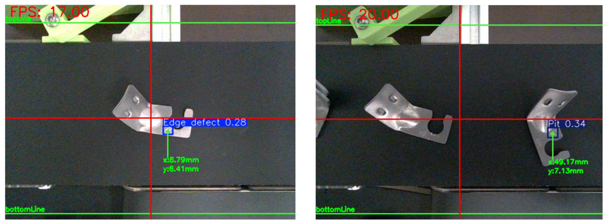
To achieve real-time surface defect detection for moving parts, this study evaluates the proposed YOLO-CGMS model under realistic dynamic conditions using the simulated conveyor platform. During testing, samples with various defect characteristics were randomly placed on the conveyor belt and transported through the camera’s imaging zone at a constant speed. The system tracked the entire process from when a workpiece entered the field of view until it left the inspection area (Figure 17). The experiment used six sample categories: qualified parts (no defects) and five types of defective parts (edge material deficiency, dents, oil contamination, punching deviation, and scratches), with 50 samples per category. By comparing the algorithm outputs against the ground truth (Table 8), we noted that while detection accuracy dropped slightly in the continuous-frame dynamic environment compared to static single-frame testing, the model still maintained robust overall recognition. Consequently, the proposed approach fully meets the accuracy requirements for practical automated sorting systems.

3.10.2. Dynamic Detection and Sorting Experiments

To evaluate the prototype system’s performance under realistic production conditions, dynamic detection and sorting trials were conducted in a laboratory environment. Designed to mimic a manual visual inspection workflow, individual defective samples were randomly introduced onto a steady-moving conveyor belt with clear spacing. As each part passed through the machine vision unit, the industrial camera captured its image for real-time defect recognition. Upon reaching a predefined inspection line, the algorithm output the precise coordinates of the flagged workpiece, prompting the control unit to calculate a motion trajectory and command the Delta robot to execute the sorting action.
To isolate the dynamic handling capability of the prototype system, this evaluation focused on defective items, excluding qualified parts from the sorting loop. Across 200 individual trials performed under this single-item configuration, the results summarized in Table 9 show that the integrated system achieved an average sorting success rate of 80.5% with a mean execution time of 2.6 s per workpiece. These results indicate that the proposed system can connect visual defect detection, coordinate mapping, trajectory planning, and robotic execution into a complete dynamic sorting workflow under laboratory prototype conditions. However, the sorting success rate of 80.5% also suggests that the current system still has practical limitations, and further improvements are required before long-term industrial deployment.
It should be noted that the sorting success rate of 80.5% represents the feasibility of the prototype system under laboratory conditions, but it also indicates that the current system still has practical limitations. Based on the experimental observations, the sorting failures were mainly related to three factors. First, metallic surface reflection may weaken or obscure fine defect features, especially scratches, edge defects, and punching deviation, leading to missed or incorrect recognition. Second, errors may accumulate during the complete dynamic sorting chain, including image-based target localization, camera-to-robot coordinate mapping, conveyor motion prediction, communication delay, and robot execution. Third, because the stamped parts are small and irregular in shape, the suction end-effector is sensitive to target-position deviation. When the actual suction point deviates from the stable adsorption region, the workpiece may fail to be picked up or may fall during transfer.

4. Conclusions

This study developed a vision-based dynamic defect detection and robotic sorting system for small irregular stamped parts. The system combines surface image acquisition, YOLO-CGMS-based defect recognition, camera-to-robot coordinate mapping, Delta robot trajectory planning, and pneumatic suction sorting, thereby extending defect detection from static image recognition to an executable inspection-and-sorting process.
For the visual perception module, YOLO-CGMS was constructed on the basis of YOLOv8n by introducing C2f-CRM, GRF-SPPF, MCA, and Inner-GIoU. These improvements enhanced small-defect feature extraction and bounding-box regression while maintaining a lightweight model structure. On the factory-collected dataset, YOLO-CGMS achieved an mAP50 of 88.7%, an FPS of 236.23 frames/s, 2.8 M parameters, and 7.3 GFLOPs. Compared with YOLOv8n, the mAP50 increased by 5.1 percentage points, the FPS increased by 12.18 frames/s, while the parameters and GFLOPs were reduced by 0.2 M and 0.8 G, respectively. These results indicate that the model provides a practical balance between accuracy, speed, and deployability for real-time inspection.
The prototype experiments further verified the system-level feasibility. The average positioning error of the camera-to-robot coordinate mapping was 2.66 mm, satisfying the design requirement of no more than 3 mm. In 200 dynamic detection and sorting tests, 161 defective workpieces were successfully sorted, corresponding to a sorting success rate of 80.5%. The average processing time for a single workpiece was 2.6 s, which also met the required sorting cycle of no more than 3 s. These results confirm that the proposed system can convert visual detection results into robot-executable sorting actions under conveyor-based operating conditions.
Although the prototype experiments verified the feasibility of the proposed inspection and sorting workflow, the current system is still at the laboratory validation stage. The sorting success rate of 80.5% indicates that the system can convert visual detection results into robot-executable sorting actions, but further improvement is required before long-term industrial deployment. The main limitations include the influence of metallic reflection on fine-defect recognition, the accumulation of positioning errors during coordinate mapping and conveyor motion prediction, communication delay between the vision unit and the controller, structural and repeatability errors of the Delta robot, and suction-position deviation caused by the small and irregular workpiece shape. Future work will focus on optimizing the illumination system, expanding the dataset under different illumination and production conditions, introducing conveyor speed feedback, establishing delay compensation, improving online calibration, optimizing the suction end-effector, and using visual servo correction to improve sorting stability and positioning accuracy.

Author Contributions

Conceptualization, H.T. and H.W.; methodology, H.T. and H.W.; software, H.T., Y.W. and Y.B.; validation, Y.B. and X.L.; formal analysis, H.T. and Y.B.; investigation, H.T., Y.W. and X.L.; data curation, Y.B. and X.L.; visualization, Y.W. and X.L.; supervision, H.W. and F.S.; writing—original draft preparation, H.T. and Y.B.; writing—review and editing, Y.B., H.W. and F.S. All authors have read and agreed to the published version of the manuscript.

Funding

This research was funded by the Natural Science Foundation of Sichuan Province (Grant No. 2026NSFSC1511).

Data Availability Statement

The data presented in this study are available on request from the corresponding author. Due to legal restrictions, data cannot be shared publicly.

Conflicts of Interest

The authors declare no conflicts of interest.

References

  1. Wu, H.; Li, X.; Sun, F.; Huang, L.; Yang, T.; Bian, Y.; Lv, Q. An Improved Product Defect Detection Method Combining Centroid Distance and Textural Information. Electronics 2024, 13, 3798. [Google Scholar] [CrossRef] [Scilit]
  2. Wu, H.; Luo, Z.; Sun, F.; Li, X.; Zhao, Y. An Improvement Method for Improving the Surface Defect Detection of Industrial Products Based on Contour Matching Algorithms. Sensors 2024, 24, 3932. [Google Scholar] [CrossRef] [Scilit] [PubMed]
  3. Yu, Q.; Wu, Q.; Liu, H. Research on X-ray Contraband Detection and Overlapping Target Detection Based on Convolutional Network. In Proceedings of the 2022 4th International Conference on Frontiers Technology of Information and Computer (ICFTIC), Qingdao, China, 2–4 December 2022; pp. 736–741. [Google Scholar]
  4. Redmon, J.; Farhadi, A. YOLO9000: Better Faster Stronger. In Proceedings of the 2017 IEEE Conference on Computer Vision and Pattern Recognition (CVPR), Honolulu, HI, USA, 21–26 July 2017; pp. 7263–7271. [Google Scholar]
  5. Liu, W.; Anguelov, D.; Erhan, D.; Szegedy, C.; Reed, S.; Fu, C.; Berg, A.C. SSD: Single Shot Multibox Detect. In Computer Vision—ECCV 2016, Proceedings of the 14th European Conference, Amsterdam, The Netherlands, 11–14 October 2016; Springer: Cham, Switzerland, 2016; pp. 21–37. [Google Scholar]
  6. Girshick, R.; Donahue, J.; Darrell, T.; Malik, J. Rich Feature Hierarchies for Accurate Object Detection and Semantic Segmentation. In Proceedings of the 2014 IEEE Conference on Computer Vision and Pattern Recognition (CVPR), Columbus, OH, USA, 23–28 June 2014; pp. 580–587. [Google Scholar]
  7. Girshick, R. Fast R-CNN. In Proceedings of the 2015 IEEE International Conference on Computer Vision (ICCV), Santiago, Chile, 7–13 December 2015; pp. 1440–1448. [Google Scholar]
  8. Ren, S. Faster R-CNN: Towards Real-Time Object Detection with Region Proposal Networks. arXiv 2015, arXiv:1506.01497. [Google Scholar]
  9. Carion, N.; Massa, F.; Synnaeve, G.; Usunier, N.; Kirillov, A.; Zagoruyko, S. End-to-end Object Detection with Transformers. In Computer Vision—ECCV 2020, Proceedings of the 16th European Conference, Glasgow, UK, 23–28 August 2020; Springer: Cham, Switzerland, 2020; pp. 213–229. [Google Scholar]
  10. Chen, F.; Deng, M.; Gao, H.; Yang, X.; Zhang, D. Aca-net: An adaptive convolution and anchor network for metallic surface defect detection. Appl. Sci. 2022, 12, 8070. [Google Scholar] [CrossRef] [Scilit]
  11. Wang, J.; Song, K.; Zhang, D.; Niu, M.; Yan, Y. Collaborative learning attention network based on RGB image and depth image for surface defect inspection of no-service rail. IEEE/ASME Trans. Mechatron. 2022, 27, 4874–4884. [Google Scholar] [CrossRef] [Scilit]
  12. Liu, J.; Liu, C.; Wu, Y.; Sun, Z.; Xu, H. Insulators’ identification and missing defect detection in aerial images based on cascaded YOLO models. Comput. Intell. Neurosci. 2022, 2022, 7113765. [Google Scholar] [CrossRef] [Scilit] [PubMed]
  13. Li, S.; Guo, S.; Han, Z.; Kou, C.; Huang, B.; Luan, M. Aluminum surface defect detection method based on a lightweight YOLOv4 network. Sci. Rep. 2023, 13, 11077. [Google Scholar] [CrossRef] [Scilit] [PubMed]
  14. Liu, J.; Cui, G.; Xiao, C. A real-time and efficient surface defect detection method based on YOLOv4. J. Real.-Time Image Process. 2023, 20, 77. [Google Scholar] [CrossRef] [Scilit]
  15. Howard, A.G.; Zhu, M.; Chen, B.; Kalenichenko, D.; Wang, W.; Weyand, T.; Andreetto, M.; Adam, H. Mobilenets: Efficient convolutional neural networks for mobile vision applications. arXiv 2017, arXiv:1704.04861. [Google Scholar]
  16. Sandler, M.; Howard, A.; Zhu, M.; Zhmoginov, A.; Chen, L. Mobilenetv2 Invert. Residuals Linear Bottlenecks. In Proceedings of the 2018 IEEE Conference on Computer Vision and Pattern Recognition (CVPR), Salt Lake City, UT, USA, 18–23 June 2018; pp. 4510–4520. [Google Scholar]
  17. Howard, A.; Sandler, M.; Chu, G.; Chen, L.; Chen, B.; Tan, M.; Wang, W.; Zhu, Y.; Pang, R.; Vasudevan, V. Searching for MobileNetV3. In Proceedings of the 2019 IEEE/CVF International Conference on Computer Vision (ICCV), Seoul, Republic of Korea, 27 October–2 November 2019; pp. 1314–1324. [Google Scholar]
  18. Ji, L.; Huang, C.H. Improved YOLOv5 Network for Aviation Plug Defect Detection. Aerospace 2024, 11, 488. [Google Scholar] [CrossRef] [Scilit]
  19. Zhao, C.; Shu, X.; Yan, X.; Zuo, X.; Zhu, F. RDD-YOLO: A modified YOLO for detection of steel surface defects. Measurement 2023, 214, 112776. [Google Scholar] [CrossRef] [Scilit]
  20. Wu, S.; Gan, X.Y.; Xiao, J.; Ma, C.; Deng, T.Y.; Du, Z.B.; Qiu, W. Online insulator defects detection and application based on YOLOv7-tiny algorithm. Front. Energy Res. 2024, 12, 1372618. [Google Scholar] [CrossRef] [Scilit]
  21. Dong, X.; Zhang, C.; Wang, J.; Chen, Y.; Wang, D. Real-time detection of surface cracking defects for large-sized stamped parts. Comput. Ind. 2024, 159, 104105. [Google Scholar] [CrossRef] [Scilit]
  22. Singh, S.A.; Choudhari, S.J.; Desai, K.A. Augmenting human-guided progressive learning with machine vision systems for robust surface defect detection. Adv. Eng. Inform. 2024, 62, 102906. [Google Scholar] [CrossRef] [Scilit]
  23. Gouveia, E.L.; Lyons, J.G.; Devine, D.M. Implementing a Vision-Based ROS Package for Reliable Part Localization and Displacement from Conveyor Belts. J. Manuf. Mater. Process. 2024, 8, 218. [Google Scholar] [CrossRef] [Scilit]
  24. Varghese, R.; Sambath, M. YOLOv8: A Novel Object Detection Algorithm with Enhanced Performance and Robustness. In Proceedings of the 2024 International Conference on Advances in Data Engineering and Intelligent Computing Systems (ADICS), Chennai, India, 18–19 April 2024; pp. 1–6. [Google Scholar]
  25. Li, J.; Wen, Y.; He, L. SCConv: Spatial and Channel Reconstruction Convolution for Feature Redundancy. In Proceedings of the 2023 IEEE/CVF Conference on Computer Vision and Pattern Recognition (CVPR), Vancouver, BC, Canada, 17–24 June 2023; pp. 6153–6162. [Google Scholar]
  26. Li, X.; Wang, W.; Hu, X.; Yang, J. Selective Kernel Networks. In Proceedings of the 2019 IEEE/CVF Conference on Computer Vision and Pattern Recognition, Long Beach, CA, USA, 15–20 June 2019; pp. 510–519. [Google Scholar]
  27. Zhang, H.; Xu, C.; Zhang, S. Inner-IoU: More effective intersection over union loss with auxiliary bounding box. arXiv 2023, arXiv:2311.02877. [Google Scholar]
  28. Rezatofighi, H.; Tsoi, N.; Gwak, J.; Sadeghian, A.; Reid, I.; Savarese, S. Generalized intersection over union: A metric and a loss for bounding box regression. In Proceedings of the 2019 IEEE/CVF Conference on Computer Vision and Pattern Recognition (CVPR), Long Beach, CA, USA, 15–20 June 2019; pp. 658–666. [Google Scholar]
  29. Woo, S.; Park, J.; Lee, J.; Kweon, I.S. CBAM: Convolutional Block Attention Module. In Computer Vision—ECCV 2018, Proceedings of the 5th European Conference, Munich, Germany, 8–14 Sepetember 2018; Springer: Cham, Switzerland, 2018; pp. 3–19. [Google Scholar]
  30. Zhang, Q.; Yang, Y. SA-Net: Shuffle Attention for Deep Convolutional Neural Networks. In Proceedings of the ICASSP 2021—2021 IEEE International Conference on Acoustics, Speech and Signal Processing (ICASSP), Toronto, ON, Canada, 6–11 June 2021; pp. 2235–2239. [Google Scholar]
  31. Lee, H.; Kim, H.; Nam, H. SRM: A Style-Based Recalibration Module for Convolutional Neural Networks. In Proceedings of the 2019 IEEE/CVF International Conference on Computer Vision (ICCV), Seoul, Republic of Korea, 27 October–2 November 2019; pp. 1854–1862. [Google Scholar]
  32. Wang, Q.; Wu, B.; Zhu, P.; Li, P.; Zuo, W.; Hu, Q. ECA-Net: Efficient Channel Attention for Deep Convolutional Neural Networks. In Proceedings of the 2020 IEEE/CVF Conference on Computer Vision and Pattern Recognition (CVPR), Seattle, WA, USA, 13–19 June 2020; pp. 11534–11542. [Google Scholar]
  33. Yang, L.; Zhang, R.; Li, L.; Xie, X. SimAM: A Simple, Parameter-Free Attention Module for Convolutional Neural Networks. In Proceedings of the 38th International Conference on Machine Learning, Virtual, 18–24 July 2021; pp. 11863–11874. [Google Scholar]
  34. Selvaraju, R.R.; Cogswell, M.; Das, A.; Vedantam, R.; Parikh, D.; Batra, D. Grad-CAM: Visual Explanations From Deep Networks via Gradient-Based Localization. In Proceedings of the 2017 IEEE International Conference on Computer Vision (ICCV), Venice, Italy, 22–29 October 2017; pp. 618–626. [Google Scholar]
  35. Redmon, J. Yolov3: An incremental improvement. arXiv 2018, arXiv:1804.02767. [Google Scholar]
  36. Jocher, G.; Chaurasia, A.; Stoken, A.; Borovec, J.; Kwon, Y.; Michael, K.; Fang, J.; Yifu, Z.; Wong, C.; Montes, D. Ultralytics/yolov5: V7.0: YOLOv5 SOTA Realtime Instance Segmentation. Zenodo. 2022. Available online: https://zenodo.org/records/7347926 (accessed on 9 June 2026).
  37. Li, C.; Li, L.; Jiang, H.; Weng, K.; Geng, Y.; Li, L.; Ke, Z.; Li, Q.; Cheng, M.; Nie, W. YOLOv6: A single-stage object detection framework for industrial applications. arXiv 2022, arXiv:2209.02976. [Google Scholar]
  38. Wang, C.; Bochkovskiy, A.; Liao, H.M. YOLOv7: Trainable bag-of-freebies sets new state-of-the-art for real-time object detectors. In Proceedings of the 2023 IEEE/CVF Conference on Computer Vision and Pattern Recognition (CVPR), Vancouver, BC, Canada, 17–24 June 2023; pp. 7464–7475. [Google Scholar]
  39. Zhao, Y.; Lv, W.; Xu, S.; Wei, J.; Wang, G.; Dang, Q.; Liu, Y.; Chen, J. DETRs Beat YOLOs on Real-time Object Detection. In Proceedings of the 2024 IEEE/CVF Conference on Computer Vision and Pattern Recognition (CVPR), Seattle, WA, USA, 16–22 June 2024; pp. 16965–16974. [Google Scholar]
Figure 1. Structure of the surface defect detection and sorting system for small irregular stamped parts.
Machines 14 00784 g001
Figure 2. Defect types in small irregular stamped parts.
Machines 14 00784 g002
Figure 3. Shooting plan for small irregular stamping parts.
Machines 14 00784 g003
Figure 4. YOLO-CGMS network structure.
Machines 14 00784 g004
Figure 5. Multidimensional collaborative attention.
Machines 14 00784 g005
Figure 6. C2f-CRM module.
Machines 14 00784 g006
Figure 7. Schematic diagram of CRU-Conv.
Machines 14 00784 g007
Figure 8. GRF-SPPF module.
Machines 14 00784 g008
Figure 9. Schematic diagram of Inner-IoU.
Machines 14 00784 g009
Figure 10. Calibration relationship between the industrial camera and the Delta robot.
Machines 14 00784 g010
Figure 11. Improved gate-shaped sorting trajectory of the Delta robot.
Machines 14 00784 g011
Figure 12. Prototype surface defect detection system for small irregular stamped parts.
Machines 14 00784 g012
Figure 13. Overall control scheme of the detection system.
Machines 14 00784 g013
Figure 14. Comparison of YOLOv8n model and YOLO-CGMS model training curves for each assessment indicator.
Machines 14 00784 g014
Figure 15. Comparison of feature extraction ability between YOLOv8n model and YOLO-CGMS model.
Machines 14 00784 g015
Figure 16. Comparison of detection results of different models.
Machines 14 00784 g016aMachines 14 00784 g016b
Figure 17. Dynamic detection of surface defects in small irregular stamped parts.
Machines 14 00784 g017
Table 1. Data set division statistics.
Dataset Train Validation TestTotal
DefectEdge defect3514444439
Pit3804847475
Oil stain3584545448
Hole misalignment3324242416
Scratch3534545422
Defect-free 8001001001000
Table 2. Effect of different input sizes on YOLOv8 model performance.
ModelScale (Pixels)P (%)R (%)mAP50 (%)FPS (Frame/s)Params (M)GFLOPS (G)
YOLOv8n1280 × 96075.997.681.1187.053.010.4
960 × 72076.199.883.6224.058.1
720 × 54075.398.182.7314.396.8
YOLOv8s1280 × 96077.298.382.2149.2611.152.4
960 × 72078.999.183.1240.0638.9
720 × 54076.299.682.5279.1328.7
YOLOv8m1280 × 96073.898.181.7123.9125.8141.6
960 × 72079.399.983.9186.39113.9
720 × 54077.1182.4231.4388.7
YOLOv8l1280 × 96076.897.682.578.443.6219.4
960 × 72078.399.883.6107.02164.8
720 × 54077.999.783159.6135.9
YOLOv8x1280 × 96077.499.683.743.8168.1358.1
960 × 72078.599.884.287.28284.5
720 × 54077.2182.6125237.4
Table 3. Performance comparison of different attention modules.
ModelP (%)R (%)mAP50 (%)FPS (Frame/s)Params (M)GFLOPS (G)
Baseline76.199.883.6224.053.08.1
CBAM77.699.784.4354.183.08.2
SA77.998.483.1234.443.08.1
SRM78.598.384.5229.613.08.1
ECA76.899.783.8227.963.08.1
SimAM76.999.685.4214.683.08.1
MCA79.699.785.8236.373.08.1
Table 4. Effect of different Ratio values on model detection accuracy.
RatioP (%)R (%)mAP50 (%)FPS (Frame/s)Params (M)GFLOPS (G)
0.579.997.987.3228.382.87.3
0.679.298.387.2220.53
0.77998.887.6222.29
0.879.198.987.9225.92
0.980.699.788.7236.23
1.07997.887.3221.54
1.17998.888.6226.8
1.280.297.788.4224.32
1.37998.686.7226.06
1.47996.486.9222.83
1.579.197.686.3226.66
Table 5. Results of ablation experiments.
ModuleMCAC2f-CRMGRF-SPPFInner-GIoUP (%)R (%)mAP50 (%)FPS (Frame/s)Params (M)GFLOPS (G)
YOLOv8n××××76.199.883.6224.053.08.1
×××79.699.785.8236.373.08.1
×××81.399.786.3234.852.67.2
×××79.499.485.4223.683.18.2
×××79.999.585.2225.693.08.1
××80.89986.2233.32.67.2
×81.299.587.5235.12.87.3
80.699.788.7236.232.87.3
Note: × indicates that the module is not adopted, and √ indicates that the module is adopted.
Table 6. Comparison between YOLO-CGMS model and YOLOv8n model.
ModelP (%)R (%)mAP50 (%)FPS (Frame/s)Params (M)GFLOPS(G)
Yolov8n76.199.883.6224.053.08.1
YOLO-CGMS80.6 (+4.5)99.7 (−0.1)88.7 (+5.1)236.23 (+12.18)2.8 (−0.2)7.3 (−0.8)
Table 7. Comparison experiments of different models.
ModelP (%)R (%)mAP50 (%)FPS (Frame/s)Params(M)GFLOPS(G)
YOLOv3-tiny69.186.975.4196.498.6813
YOLOv5n77.597.282.3216.681.774.2
YOLOv6s72.793.481.9184.7617.244.0
YOLOv7-tiny74.897.382.2218.526.0113.10
YOLOv8n76.199.883.6224.053.08.1
RT-DETR83.398.989.1112.1732.82110
YOLO-CGMS80.699.788.7236.232.87.3
Table 8. Results of the dynamic detection experiment.
CategoryNumber of SamplesAlgorithm Recognition Result
Number of CorrectNumber of Errors
Qualified workpieces50482
Workpieces with edge material deficiency50446
Workpieces with dents50473
Workpieces with oil contamination50491
Workpieces with punching deviation50464
Workpieces with scratches50428
Table 9. Dynamic Detection and Sorting Results.
No.Sample SizeSuccessful SortsFailed SortsSorting Time per PartSorting Success Rate
15038122.676
2504372.786
3504192.682
45039112.578
Total200161392.680.5
Disclaimer/Publisher’s Note: The statements, opinions and data contained in all publications are solely those of the individual author(s) and contributor(s) and not of MDPI and/or the editor(s). MDPI and/or the editor(s) disclaim responsibility for any injury to people or property resulting from any ideas, methods, instructions or products referred to in the content.