1. Background
Nuclear power is an important baseload energy source because of its low-carbon characteristics and stable operating capability. In a nuclear steam-turbine system, the reheat valve assembly is a safety-critical component that directly affects steam-flow regulation, turbine overspeed protection, and safe shutdown. Early nuclear turbine units in China relied heavily on imported reheat valve assemblies, and although domestic products have been introduced in recent projects, full localization remains limited. With the increasing deployment of 1000 MW-class nuclear units, the high cost, maintenance difficulty, long spare-part lead time, and export restrictions associated with imported components have become increasingly prominent. These challenges make it necessary to clarify the failure mechanisms of domestically substituted reheat-valve actuators and to develop engineering-oriented optimization methods.
Recent studies have examined different aspects of reheat systems. Pratama et al. [
1] developed a mathematical model and Simulink-based dynamic simulation platform for the DEH control system of a small-capacity fossil-fuel turbine, analyzing actuator dynamic response and PID parameters. Bing and Ye [
2] established a multibody dynamic model for a supercritical reheat stop valve mechanism to study impact, vibration, and jamming caused by clearance and wear. Dong et al. [
3] used probabilistic methods to evaluate how manufacturing tolerances and misalignment influence closing reliability. Dong and Ye [
4] incorporated geometric tolerances, shaft misalignment, and thermal shock into a unified model to assess closing time, impact load, and failure risk. Zhao et al. [
5] analyzed the cracking and leakage mechanism of the gland-steam drain pipeline of the reheat stop valve of Qinshan Unit III and proposed retrofit solutions. In addition, extensive research has been conducted on hydraulic system optimization. Xu et al. established the systematic mathematical and simulation model of complex hydraulic systems, providing an important analytical framework for the nuclear reheat valve system [
6,
7,
8]. Although significant progress has been achieved in the analysis of reheat stop valves, research specifically targeting the hydraulic oil-motor actuator and its closing failure mechanisms remains limited. In large thermal and nuclear power plants, field investigations show that closing timeout, incomplete closing, and sticking phenomena are often associated with degradation of the hydraulic actuator subsystem, including servo valve spool stiction, cartridge-valve flow restriction, disc spring fatigue, and gear–rack transmission backlash. Recent studies have further demonstrated that the fast-closing performance of turbine valves is highly sensitive to throttling orifice design, hydraulic damping characteristics, and spring–load nonlinearity, which directly influence the dynamic stiffness and response lag of the actuator under transient conditions [
9,
10,
11]. In nuclear-grade actuation systems, the safety-related requirements are even more stringent, as the valve must guarantee reliable fast closing under a single failure and withstand long-term cyclic loading without performance decay. Vacca et al. [
12] analyzed the dynamic behaviour of high-pressure cartridge valves used in safety-critical actuation systems and revealed that insufficient flow capacity or delayed poppet response may lead to pronounced closing delays. Similarly, tribological studies on steam-turbine valve stems indicate that wear, friction instability, and eccentric loading significantly contribute to jamming risks during fast-closing [
13,
14]. Recent studies on hydraulic actuators, valve dynamics, fluid–structure interaction, and CFD-assisted valve analysis have provided useful insights into transient valve behaviour. In particular, visualization experiments combined with CFD simulations have been used to reveal valve motion, diaphragm displacement, pressure variation, and internal flow evolution. These studies demonstrate the value of integrating experimental observation with numerical modelling [
15]. However, most CFD-assisted studies focus mainly on local flow characteristics, whereas the closing timeout problem investigated here involves the coupled effects of spring driving force, hydraulic pressure relief, mechanical transmission resistance, and load torque. Moreover, some intelligent methods including deep-learning networks have been used by inputting the signals to simulate the dynamic process, which provided the solution to monitor the fast-closing status in real time [
16,
17,
18]. However, this type of method lacks mechanics analysis, which is unfavourable for fault tracing and root-cause analysis.
These findings highlight that the reheat-valve actuator should be treated as a coupled nonlinear system involving mechanical, hydraulic, and control system interactions. At a broader mechanics level, related studies under externally imposed constraint have also shown that loading environment can substantially alter deformation response and structural evolution.
A systematic investigation that integrates coned-disc spring mechanics, hydraulic transient behaviour, actuator kinematics, and transmission resistance is therefore required to reveal the closing timeout mechanism. In particular, limited attention has been paid to the time-sequence characteristics of reheat control-valve closing, the transition between rapid- and slow-closing stages, and the parameter thresholds that cause closing timeout or small-opening stagnation.
To address this gap, this study establishes a coupled dynamic model of a nuclear reheat-valve oil-motor actuator and validates it using an actual actuator test platform. The main contributions are summarized: (i) a coupled hydraulic–mechanical model is developed by integrating the coned-disc spring assembly, throttling orifices, cartridge valve, hydraulic cylinder, gear–rack transmission, and load resistance; (ii) the sensitivity and critical thresholds of spring degradation and hydraulic throttling parameters are identified; and (iii) an engineering optimization strategy combining spring force compensation and hydraulic parameter matching is proposed and experimentally verified. These results provide both mechanistic insight and practical guidance for domestic substitution, field commissioning, and fault correction of nuclear reheat-valve actuator systems.
The remainder of this paper is organized as follows.
Section 2 introduces the system configuration and closing process of the reheat-valve actuator.
Section 3 presents the mathematical modelling, coupled simulation model, and experimental validation platform.
Section 4 analyzes the key factors affecting fast-closing performance and proposes the engineering optimization strategy.
Section 5 summarizes the main conclusions.
2. System Configuration
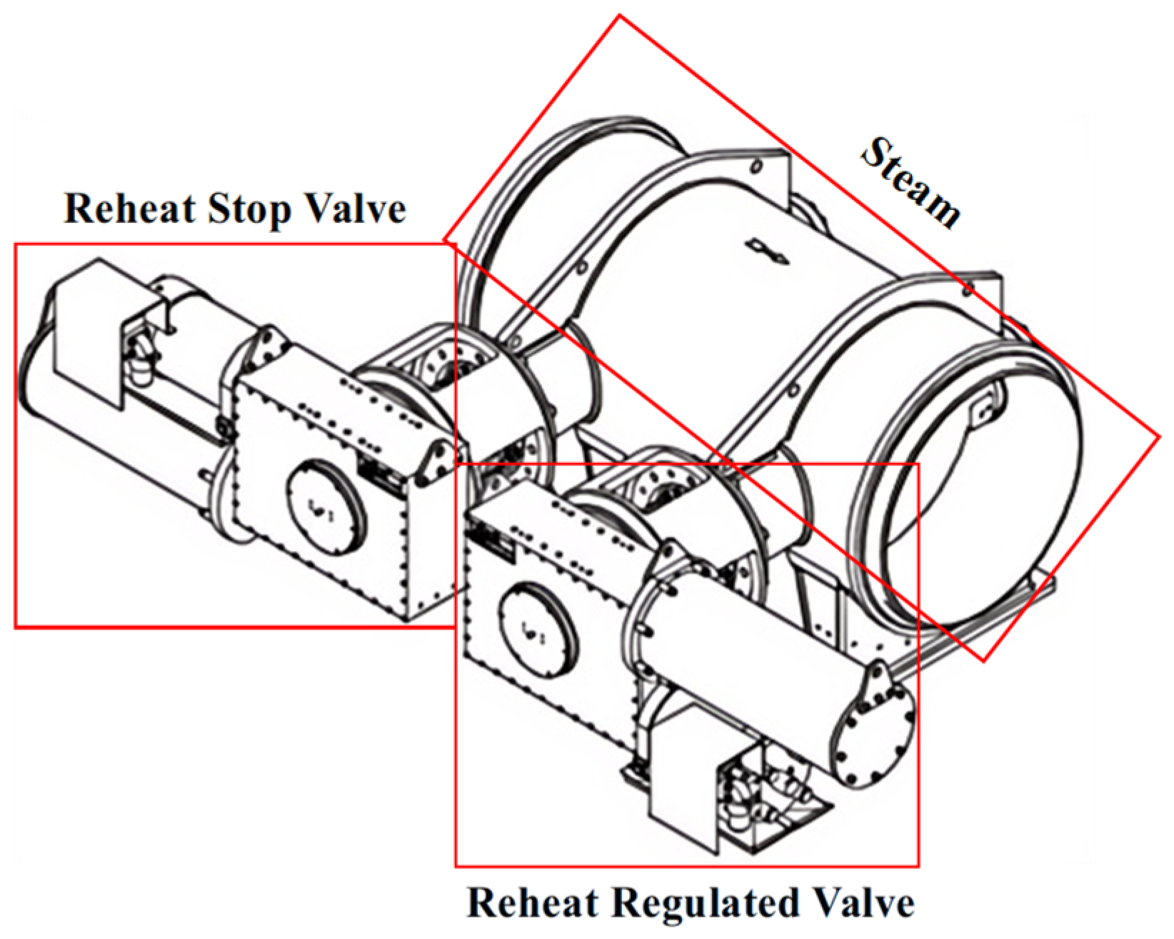
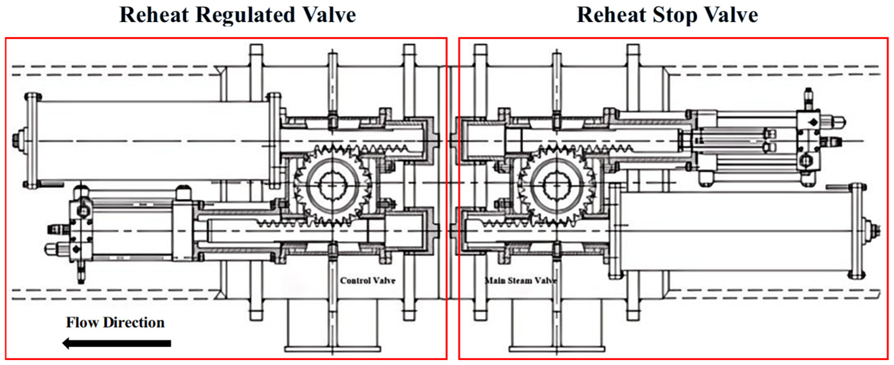
The nuclear steam-turbine reheat valve assembly consists of a reheat stop valve and a reheat control valve arranged in series, as shown in
Figure 1. It is installed on the low-pressure steam pipeline between the outlet of the steam–water separator reheater and the inlet of the low-pressure turbine. The reheat stop valve functions as a fully open/fully closed protection valve and rapidly shuts during emergency conditions to prevent turbine overspeed. The reheat control valve provides steam-flow modulation for load regulation and also participates in fast closure during load rejection. Therefore, the reliability of the reheat valve assembly directly affects turbine safety. For the nuclear unit investigated in this study, the required fast-closing time should be less than 0.8 s. The 0.8 s limit is the engineering acceptance requirement for the investigated nuclear reheat-valve actuator. This limit is determined by the overall design coordination of turbine overspeed protection, steam-flow shutoff demand, actuator stroke, valve opening angle range, hydraulic pressure-relief capacity, spring driving force, gear–rack transmission ratio, load torque, and terminal cushioning requirement. Therefore, it represents a system-level design constraint rather than a parameter obtained from a single component.
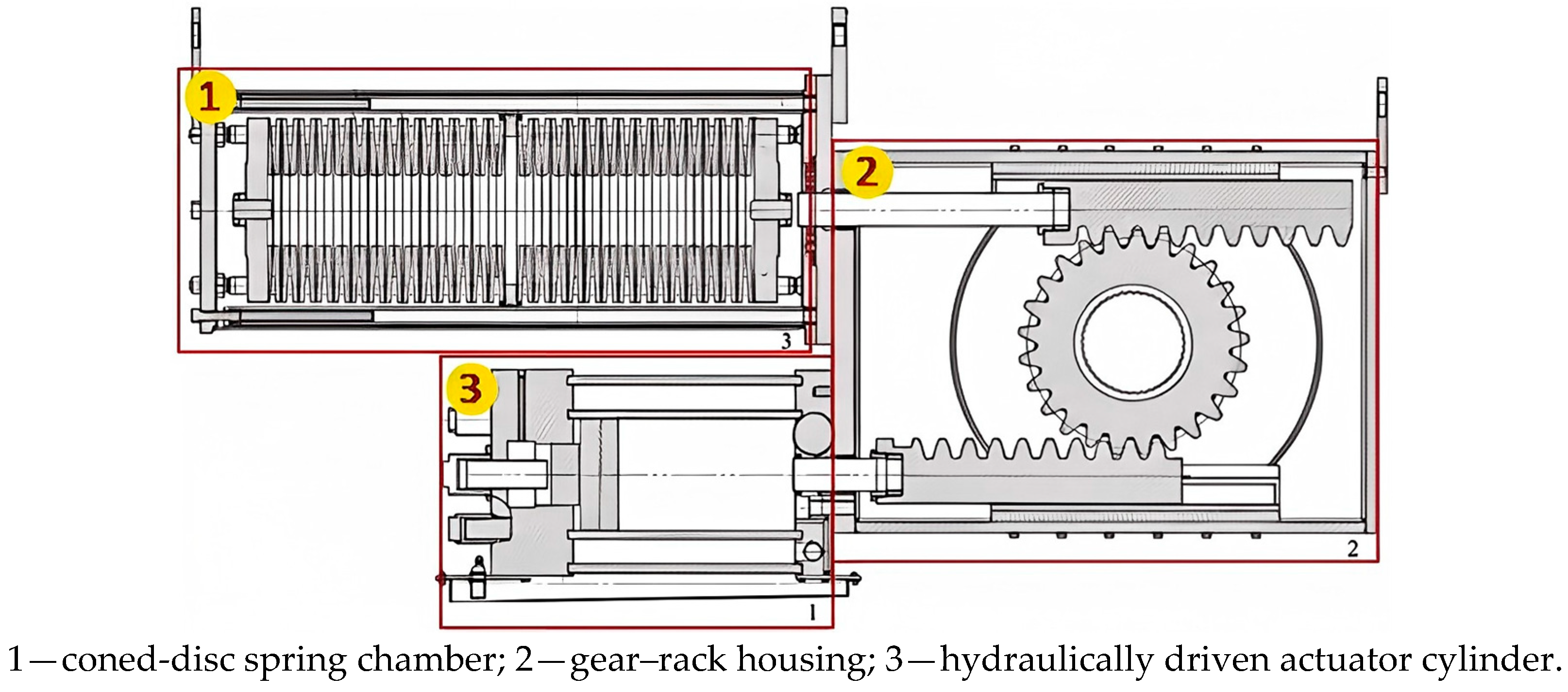
The oil-motor actuator is the core power element of the reheat-valve actuation system. It converts hydraulic energy into linear motion and transmits this motion to the butterfly-valve shaft through the gear–rack mechanism shown in
Figure 2. During valve opening, hydraulic cylinder force overcomes the resisting force of the coned-disc spring assembly and rotates the valve disc to the open position. During fast closing, the hydraulic pressure in the working chamber is released, and the stored energy of the coned-disc spring assembly provides the driving torque required to return the butterfly valve to the fully closed position. Thus, the closing response is jointly determined by the hydraulic pressure-relief capacity, spring output force, and mechanical transmission resistance.
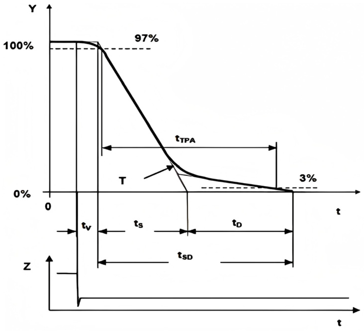
As shown in
Figure 3, the closing characteristics of the reheat valve can be described by the relationship between valve opening and closing time. The overall process consists of a system response stage (
Tv) and a fast-closing stage (
tSD). The fast-closing stage can be further divided into a rapid-closing phase and a slow-closing phase (
td). This staged response is caused by the distribution of multiple oil discharge orifices along the oil-motor cylinder stroke and is observed in both the reheat stop valve and the reheat control valve.
During closure, the actuator piston moves from left to right and the high-pressure oil in the working chamber is first discharged through the main return-flow path, corresponding to the rapid-closing phase ts. After the piston passes the main orifice, the remaining oil can only be discharged through the smaller throttling orifice. The increased flow resistance reduces the piston velocity and forms the slow-closing phase td, which provides hydraulic cushioning and reduces mechanical impact near the seated position.
3. Modelling and Simulation
3.1. Modelling of Coned-Disc Springs
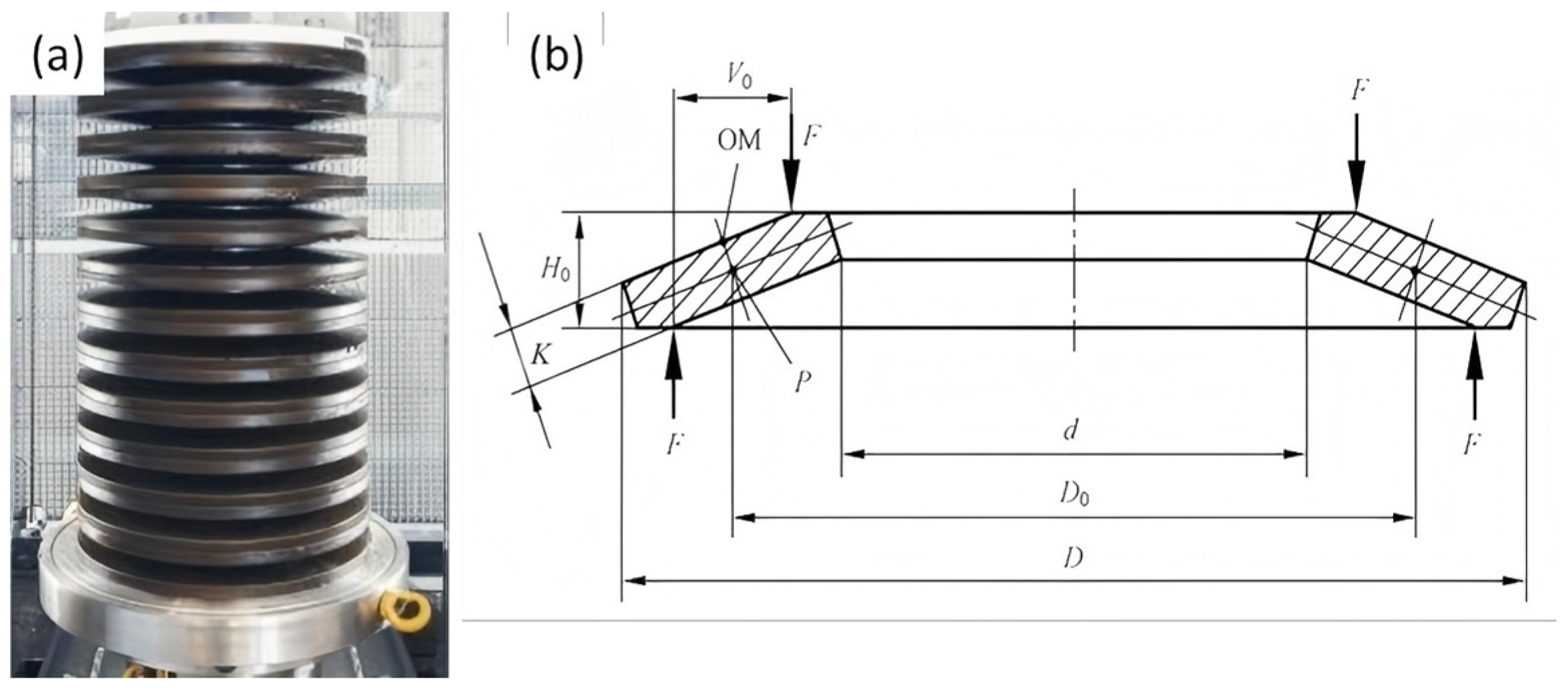
A coned-disc spring is a truncated-conical annular elastic element characterized by its outer diameter
D, inner diameter
d, thickness
t, and free height
H0. Under an axial load
F, the conical section is elastically compressed and gradually flattened, thereby providing load support, preload, buffering, and vibration attenuation.
Figure 4a shows a stacked coned-disc spring assembly whose stiffness and load capacity can be adjusted through different stacking configurations.
Figure 4b illustrates the cross-sectional geometry, loading positions, and main dimensional parameters of a single coned-disc spring.
The spring force
F of a single spring can be calculated by Equation (1) [
19,
20]:
where
D,
D0 and
d are outer, neutral diameter and inner diameter, respectively.
is the elastic modulus of the coned-disc spring material.
is the calculated deformation when the coned-disc spring is fully flattened.
is the Poisson’s ratio of the material.
t is the spring thickness.
f is the compression displacement.
and
are calculation coefficients, which are related to diameter ratio
C = D/
d and can be calculated by Equations (2)–(4):
where
tf is reduced thickness after machining.
H0 is free height of a single spring.
3.2. Modelling of the Gear–Rack Transmission System
The driving mechanism adopts a gear–rack transmission configuration, as illustrated in
Figure 5. The oil-motor actuator is installed in the lower section, whereas the coned-disc spring chamber is arranged above it; both components are located on the left side of the transmission system. In the fully closed position, the rack connected to the hydraulic cylinder meshes with the gear near the second tooth, whereas the rack connected to the coned-disc spring chamber engages between the eighth and ninth teeth. This arrangement converts the linear displacement of the oil-motor actuator into the rotational motion of the valve disc, enabling controlled opening and closing of the butterfly valve.
The key gear dimensions are as follows: the tip diameter is 484 mm, the root diameter is 370 mm, the pitch-circle diameter is 400 mm, and the number of teeth is 25. The relationship among the actuator displacement
x, the rotation angle of the reheat-valve disc, and the valve shaft diameter
D is expressed by Equation (6):
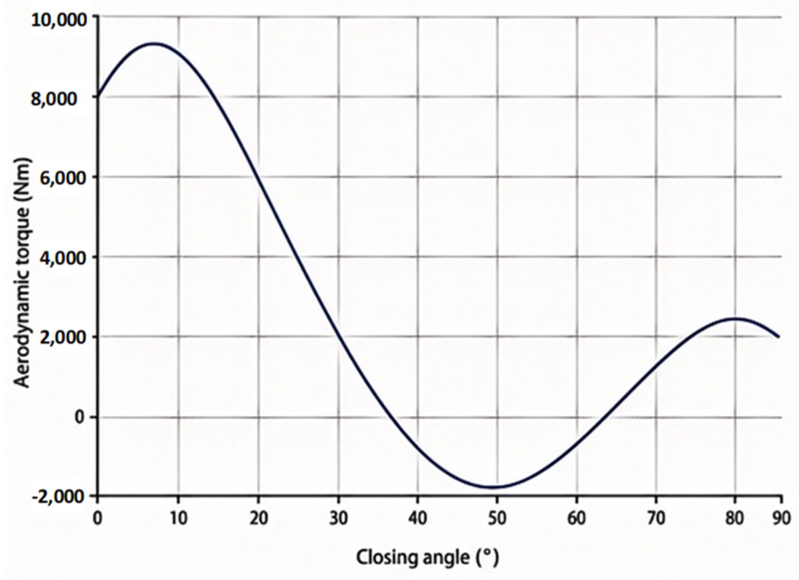
The dynamic closing torque obtained from the fast-closing experiment provided by the manufacturer was fitted using Equation (7), and the corresponding torque–angle curve is shown in
Figure 6.
The fitted curve (R2 = 0.9996) provides the load-resistance input for the subsequent coupled simulation.
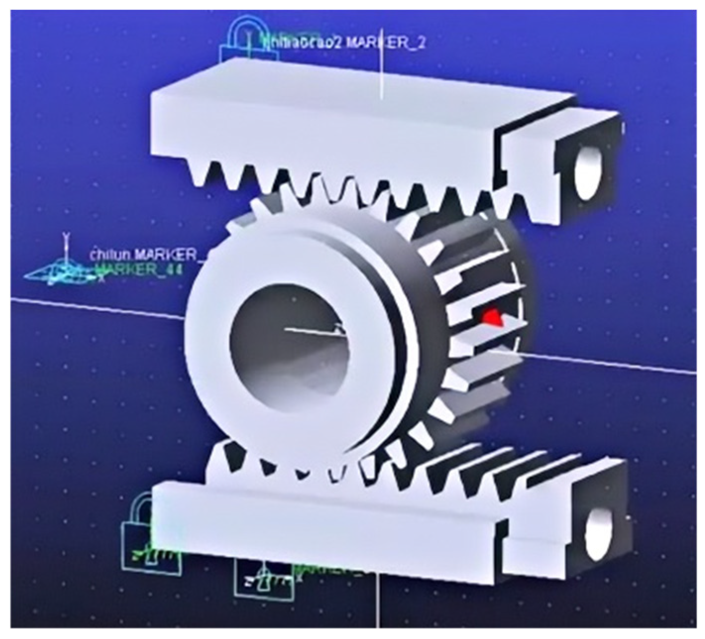
To improve the accuracy of the coupled model, the dynamic friction force in the gear–rack transmission was further evaluated using the dynamic simulation shown in
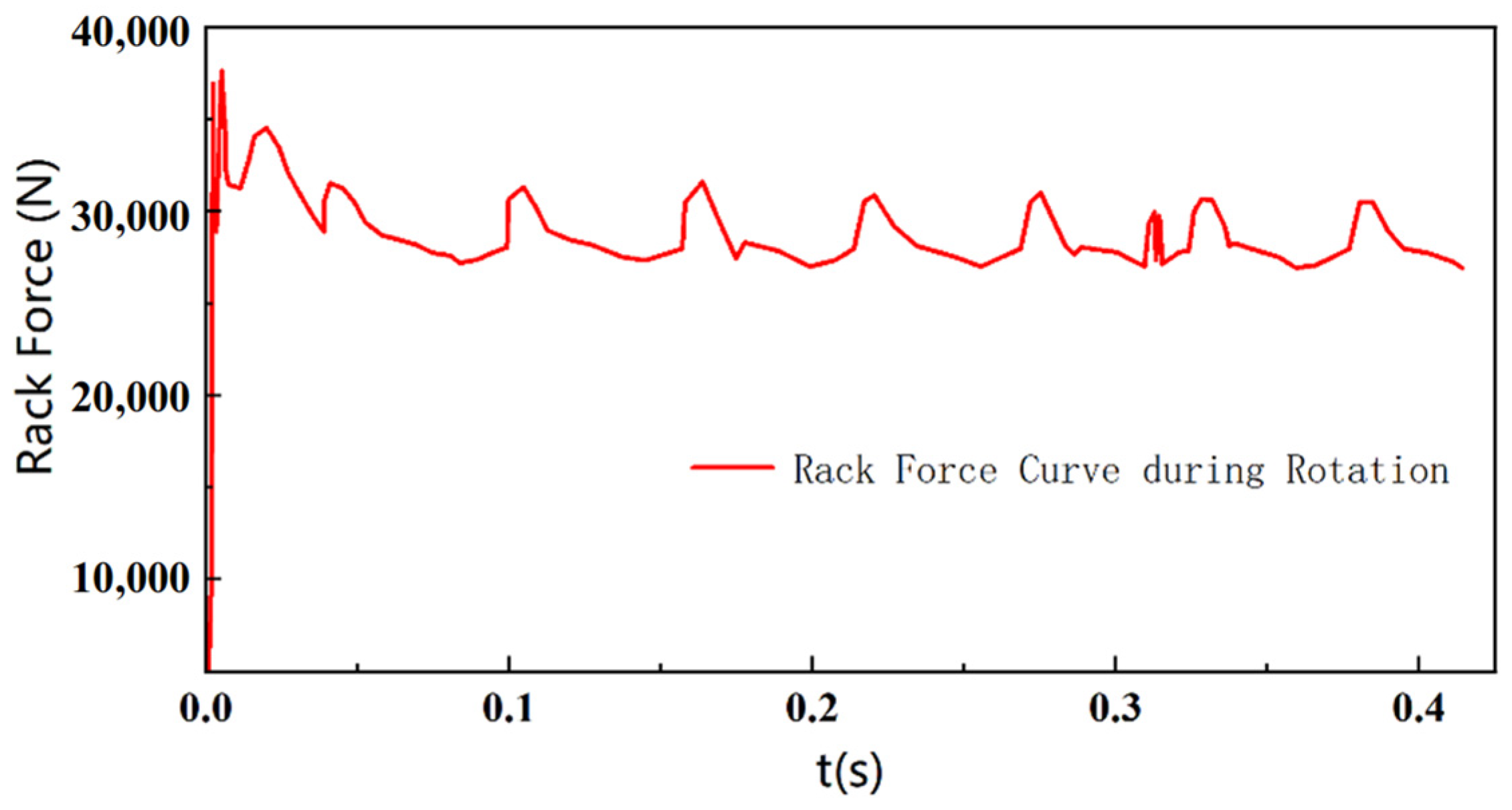
Figure 7. In this model, the driving forces generated by the hydraulic cylinder and the coned-disc spring assembly were represented by numerically defined force curves, avoiding unnecessary complexity from detailed hydraulic modelling at this stage. A revolute joint was assigned to the gear, and a translational joint was assigned to the rack to reproduce the gear–rack motion while constraining gear run-out. The resulting dynamic friction force is shown in
Figure 8. The gear–rack friction force is much smaller than the main load resistance and spring driving force, indicating that it is not the dominant factor controlling the fast-closing time. It was included mainly as an auxiliary resistance input to improve the accuracy of the coupled hydraulic–mechanical model. The gear–rack pair was assumed to work under nominal meshing and lubricated conditions, and wear evolution was not explicitly considered.
3.3. Simulation Model of the Hydraulic System
The hydraulic actuation system of the reheat valve was modelled to evaluate the dynamic response of the oil-motor actuator under normal regulation and fast-closing conditions [
15]. As shown in
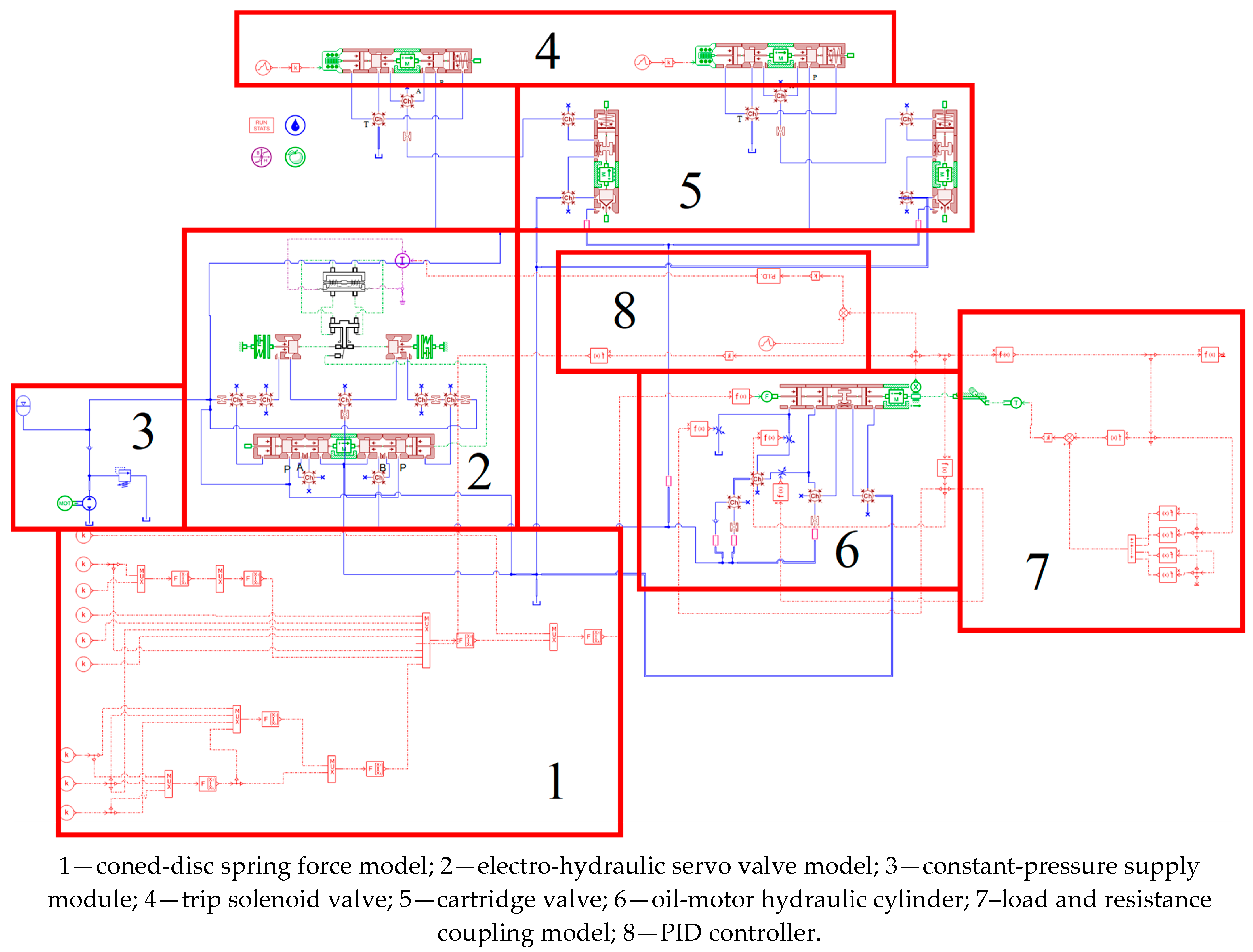
Figure 9, the model consists of eight functional modules: the coned-disc spring force model, electro-hydraulic servo valve model, constant-pressure supply module, trip solenoid valve, cartridge valve, oil-motor hydraulic cylinder, load-resistance coupling model, and PID controller. These modules describe the pressure oil supply, servo regulation, emergency oil discharge, actuator motion, and external load feedback within a unified hydraulic–mechanical framework.
During normal operation, the electro-hydraulic servo valve regulates the flow direction and flow rate of pressure oil entering the hydraulic cylinder according to the command signal from the PID controller. The resulting pressure difference drives the oil-motor actuator, and the hydraulic cylinder force is transmitted to the butterfly-valve disc through the gear–rack mechanism. Under fast-closing conditions, the trip solenoid valve and cartridge valve govern the transient pressure-relief process. Once a turbine trip signal is triggered or the safety-oil pressure is released, the trip solenoid valve switches the hydraulic circuit, and the cartridge valve rapidly connects the cylinder working chamber to the return line. The discharge capacity of this path directly affects the pressure decay rate and fast-closing time. The hydraulic cylinder is further coupled with the load-resistance model, including aerodynamic torque, frictional resistance, and the restoring force of the coned-disc spring assembly. The main parameters of the hydraulic model are listed in
Table 1.
3.4. Experimental Validation
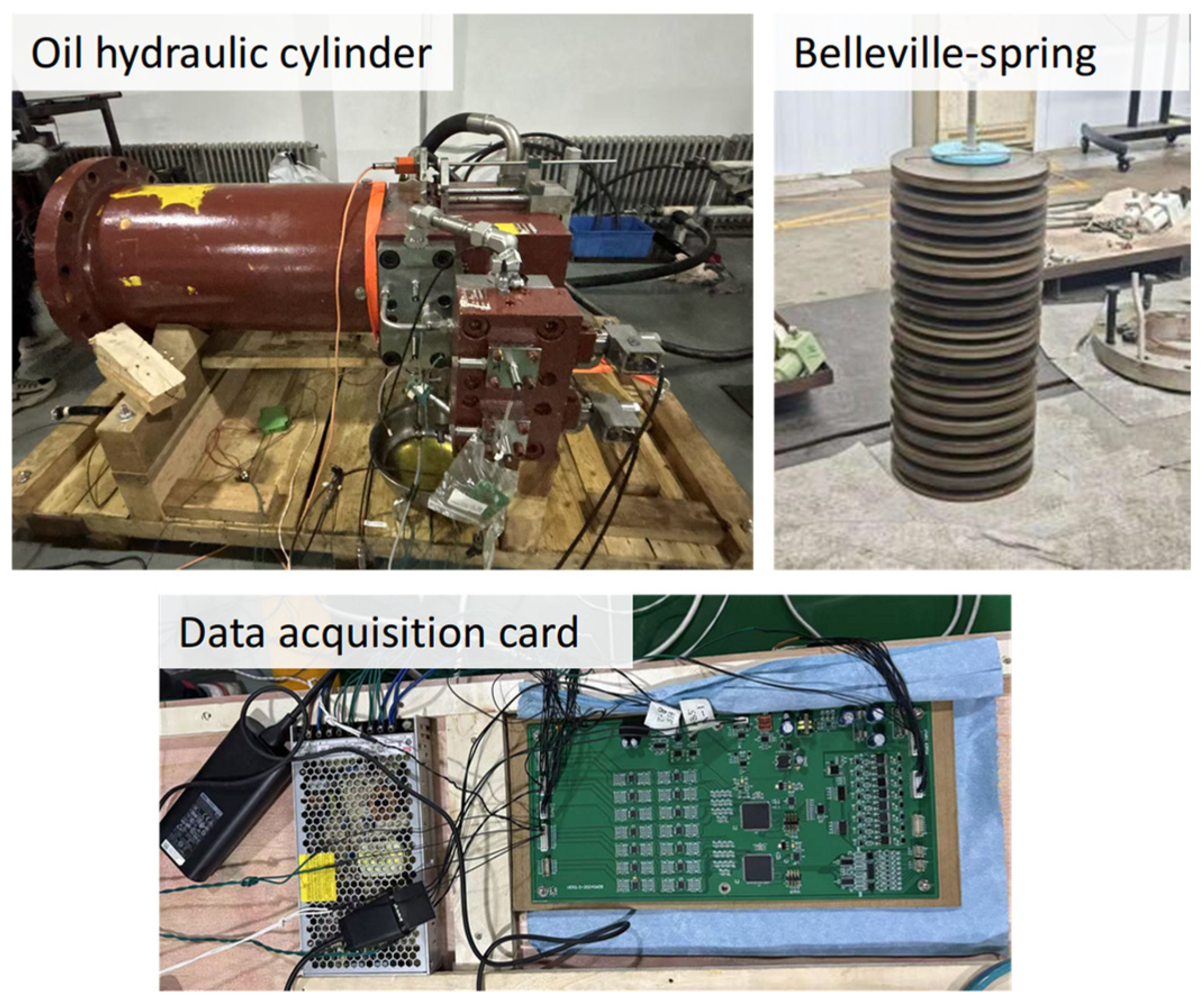
To verify the coupled hydraulic–mechanical simulation model, an experimental platform was constructed using the actual reheat-valve oil-motor actuator, as shown in
Figure 10. The platform mainly consisted of an oil hydraulic cylinder, coned-disc spring chamber, hydraulic control valve group, pressure and displacement sensors, and data acquisition card. The hydraulic cylinder reproduced the linear actuator motion, while the coned-disc spring assembly provided the restoring force during emergency closure. The data acquisition system recorded the actuator displacement, hydraulic pressure, control signal, and closing time throughout the transient fast-closing process.
Before each test, the actuator was driven to the fully open position and held until both the hydraulic pressure and displacement reached steady values. A trip command was then applied to initiate fast closure. After the trip signal, the pressure oil in the working chamber was discharged through the return-flow path, and the coned-disc spring force drove the actuator toward the closed position. The measured actuator displacement was converted into valve-opening percentage. The time required for the valve opening to decrease from 97% to 3% was defined as the effective fast-closing time and used as the key performance indicator. Based on the failure mechanism predicted by the simulation model, three representative validation cases were considered: coned-disc spring degradation, hydraulic parameter correction, and mechanical transmission resistance. Repeated tests were conducted under each condition, and the measured displacement–time curves were compared with the corresponding simulation results.
The validation focused on three aspects: the overall closing-curve trend, the 97%~3% effective fast-closing time, and the terminal-stage response near the closed position. Agreement between the experimental and simulated results demonstrates that the proposed coupled model can capture the dominant dynamic behaviour of the reheat-valve oil-motor actuator and can be used to analyze timeout-related faults and evaluate engineering correction strategies.
4. Results and Discussion
The coned-disc spring model was first validated, after which the effects of spring performance degradation, stacking configuration, and throttling orifice variation on the fast-closing process were investigated. The critical parameter thresholds associated with closing timeout were then identified and the subsequent engineering optimization strategy was presented and validated in the experiment.
To clarify the relative importance of the possible failure modes, the sensitivity analysis in this study was organized according to their direct influence on the effective fast-closing time, defined as the time required for the valve opening to decrease from 97% to 3%. The failure mechanisms mentioned in the Introduction can be classified into three categories: insufficient closing driving force, limited hydraulic pressure-relief capacity, and mechanical/control-related disturbances. Among them, coned-disc spring degradation directly reduces the stored mechanical energy and output force that drive the actuator after the trip command. Therefore, it affects the entire fast-closing stroke and is particularly critical in the small-opening range, where the remaining spring force must still overcome residual hydraulic pressure, valve resistance, friction, and gear–rack transmission resistance. The C0 throttling orifice was also quantitatively analyzed because it determines the main pressure-relief capacity of the working chamber and directly controls how effectively the spring force can be converted into actuator motion. In contrast, servo valve spool stiction, cartridge-valve degradation, and transmission backlash are important reliability-related mechanisms, but in the present fast-closing problem they mainly appear as secondary resistance, response delay, or local discontinuity factors. Their effects are partly represented in the hydraulic valve module and the load-resistance/transmission model; however, independent quantitative identification of these factors requires intrusive measurements or controlled degradation tests that are difficult to perform on an actual nuclear reheat-valve actuator. Therefore, this work focuses on the two first-order contributors to closing timeout, namely spring force degradation and hydraulic pressure-relief capacity, while the other mechanisms are discussed as possible secondary contributors to be further investigated in future work.
4.1. Validation of the Coned-Disc Spring Model
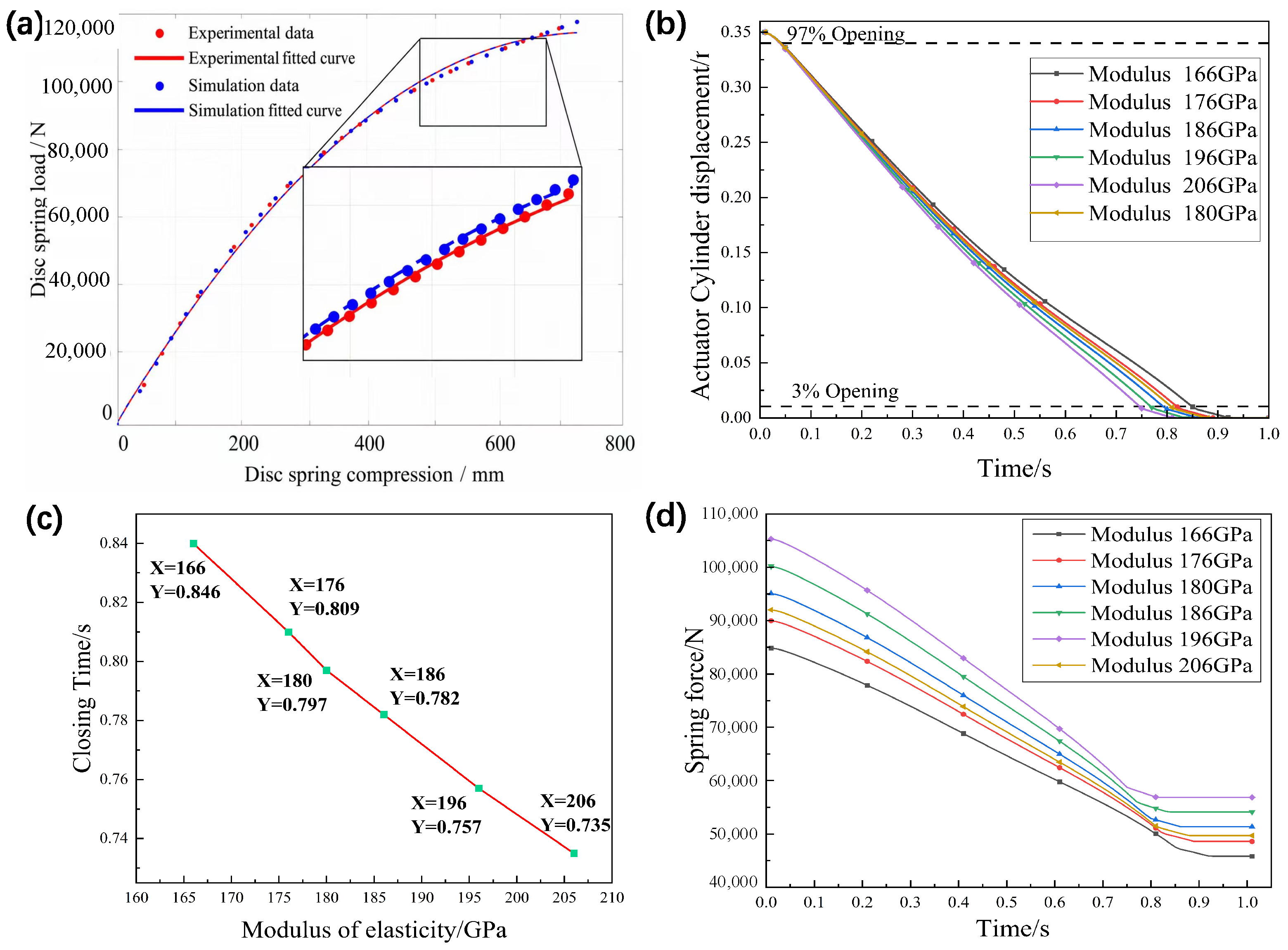
The accuracy of the coned-disc spring model directly affects the reliability of the coupled actuator model. Therefore, the simulated and experimental load-deflection characteristics of a single coned-disc spring were compared, as shown in
Figure 11a.
The reported spring model error was calculated as the average relative deviation between the simulated and measured spring force at the same deflection points. Therefore, the error below 0.5% reflects the fitting accuracy of the single coned-disc spring load-deflection model, rather than the overall uncertainty of the complete actuator system. In the oil-motor actuator, the coned-disc spring assembly continuously provides the driving force for valve closure. Its degradation is mainly manifested as reduced stiffness and insufficient output force. Cyclic loading caused by frequent opening/closing operations, creep in the high-temperature environment near the valve body, and stress relaxation under long-term pre-compression may reduce the free height, preload force, and elastic properties of the spring assembly. As a result, the driving force in the final closing stage decreases, the closing speed is reduced, and the fast-closing time may be prolonged. Therefore, the influence of the decreased equivalent elastic modulus of the coned-disc spring on the opening and fast-closing processes was further analyzed, as shown in
Figure 11b. As the equivalent elastic modulus decreases, the spring output force gradually decreases, and the actuator driving force during fast closing is correspondingly reduced, resulting in a longer closing time. Under the as-manufactured condition, the equivalent elastic modulus is approximately 206 GPa, and the time required for the valve opening to decrease from 97% to 3% is approximately 0.744 s, satisfying the fast-closing requirement. Since hydraulic oil can be regarded as nearly incompressible under the considered operating conditions, the flow rate in the hydraulic circuit is strongly correlated with the actuator displacement. Therefore, the actuator displacement curve and closing time can provide effective validation of the dynamic response of the coupled hydraulic–mechanical system [
6]. When the equivalent elastic modulus decreases to approximately 195 GPa, the fast-closing time approaches 0.8 s, which is close to the allowable limit. When the modulus further decreases to 190 GPa and 185 GPa, the closing time exceeds the specified requirement, and the timeout becomes more severe as the modulus decreases. These results indicate that degradation of the coned-disc spring assembly significantly weakens the closing driving force and is one of the main causes of reheat-valve closing timeout.
4.2. Effect of Coned-Disc Spring Stacking Configuration on the Fast-Closing Process
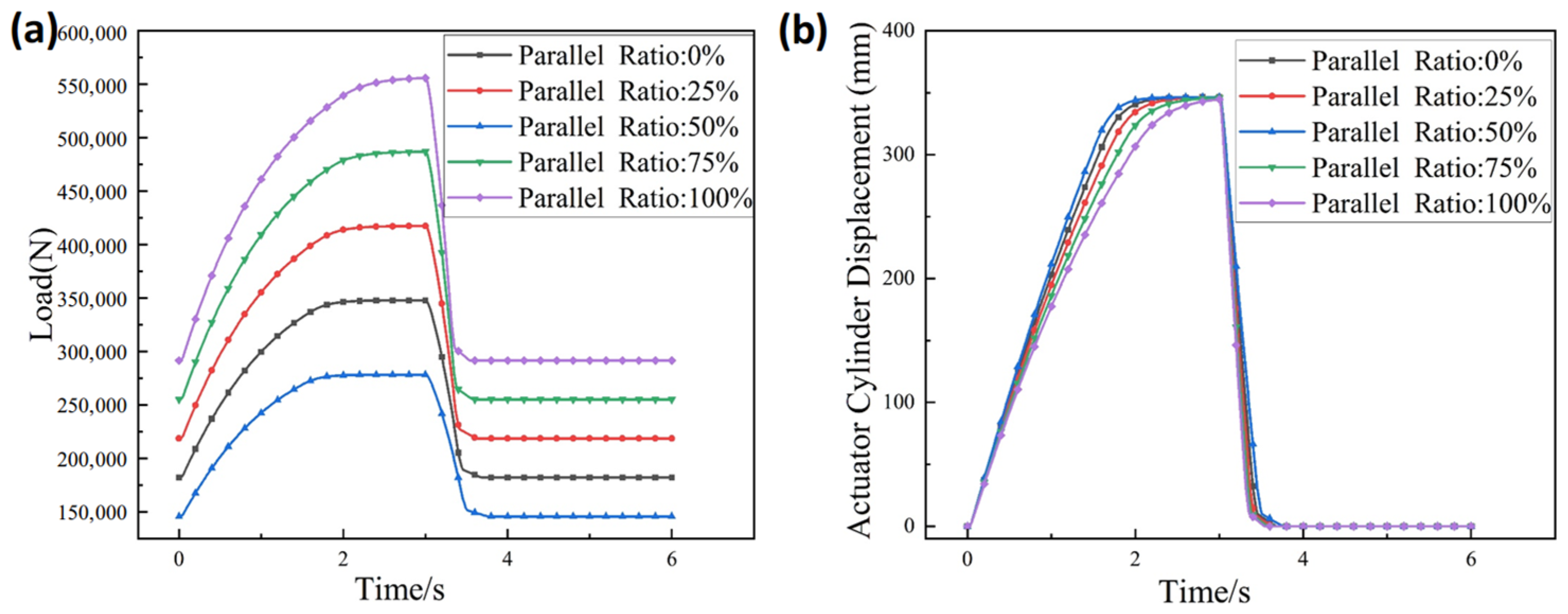
To investigate the influence of the coned-disc spring stacking configuration on overall stiffness and fast-closing response, five proportions of parallel stacking were considered in the simulation: 0%, 25%, 50%, 75%, and 100%. Here, 0% denotes a fully series-opposed configuration, whereas 100% denotes a fully parallel-stacked configuration. The other cases represent mixed stacking configurations with different degrees of parallel arrangement. The load-deflection characteristics and corresponding cylinder displacement responses are shown in
Figure 12.
As shown in
Figure 12a, increasing the proportion of parallel stacking increases the equivalent stiffness of the coned-disc spring assembly. Under the same compression displacement, the spring group generates a larger output force, thereby enhancing the driving force available during fast closure. Compared with the fully series-opposed configuration, the parallel-stacked configuration allows multiple springs to bear the load simultaneously, resulting in higher equivalent stiffness. Consequently, as shown in
Figure 12b, the actuator velocity in the initial and main closing stages increases as the parallel-stacking proportion rises from 0% to 100%, and the valve closing time is shortened. This improvement is particularly evident in the early fast-closing stage because the working-chamber pressure has not yet been fully released and hydraulic damping remains significant. A larger spring force helps overcome hydraulic resistance and mechanical friction more rapidly. In the small-opening range, where gear–rack load and valve-stem friction torque increase, enhanced spring force also helps reduce closing hysteresis and improve motion continuity.
However, the improvement obtained by increasing the proportion of parallel-stacked coned-disc springs should be balanced against long-term durability. A higher equivalent stiffness can increase the spring output force and shorten the fast-closing time, but it may also increase the peak contact stress, cyclic loading intensity, and terminal impact transmitted to the hydraulic cylinder and butterfly-valve disc. These effects may accelerate spring fatigue, stress relaxation, and wear of transmission components, thereby increasing maintenance requirements during long-term service. Therefore, the stacking configuration should not be selected solely to minimize the closing time. Instead, it should be optimized within the allowable fast-closing window while considering closing performance, terminal cushioning, fatigue life, and maintainability. In practical implementation, the increased spring stiffness should be accompanied by verification of spring force, terminal impact, and periodic inspection of the spring assembly.
4.3. Effect of the C0 Throttling Orifice on the Fast-Closing Process
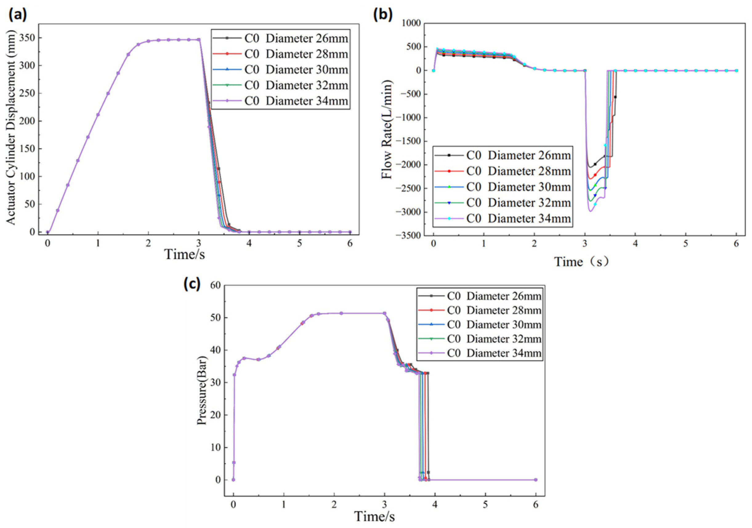
To analyze the effect of the C0 throttling orifice diameter on early-stage return-flow capacity and valve closing time, the C0 diameter was set to 26 mm, 28 mm, 30 mm, 32 mm, and 34 mm. Piston displacement, orifice flow rate, and pressure variation under different C0 diameters were then simulated, as shown in
Figure 13a–c.
The actuator exhibits markedly different closing responses under different C0 throttling orifice diameters. As the C0 diameter increases, the overall closing speed increases and the valve closing time decreases. This effect is most pronounced during the initial fast-closing and main-stroke stages, whereas the difference in the final closing stage is relatively small. These results indicate that the C0 orifice mainly governs the pressure-relief capacity of the working chamber during the early closing stage. Increasing the orifice diameter reduces return-flow resistance, accelerates pressure decay in the working chamber, and increases piston velocity.
Mechanistically, after fast closure begins, the hydraulic oil in the working chamber mainly enters the return line through the C0 throttling orifice. Thus, the C0 orifice is the key flow-control element in the main oil discharge path. When the C0 diameter is small, the return-flow capacity is restricted and a relatively high residual pressure remains in the working chamber. Under this condition, part of the coned-disc spring driving force is consumed in overcoming hydraulic resistance rather than producing closing motion, which reduces the actuator velocity. Increasing the C0 diameter improves the flow capacity of the return path, accelerates pressure relief, and allows the spring force to be converted more effectively into valve closing motion.
However, the C0 diameter should not be enlarged without constraint. Excessive enlargement increases the pressure-relief rate and instantaneous closing velocity, which may aggravate valve reseating impact and hydraulic pressure fluctuation. This would reduce motion stability and shorten the service life of hydraulic components. Therefore, the C0 throttling orifice diameter should be selected by balancing fast-closing speed, terminal buffering, and system stability while satisfying the closing time requirement.
4.4. Engineering Optimization Strategy
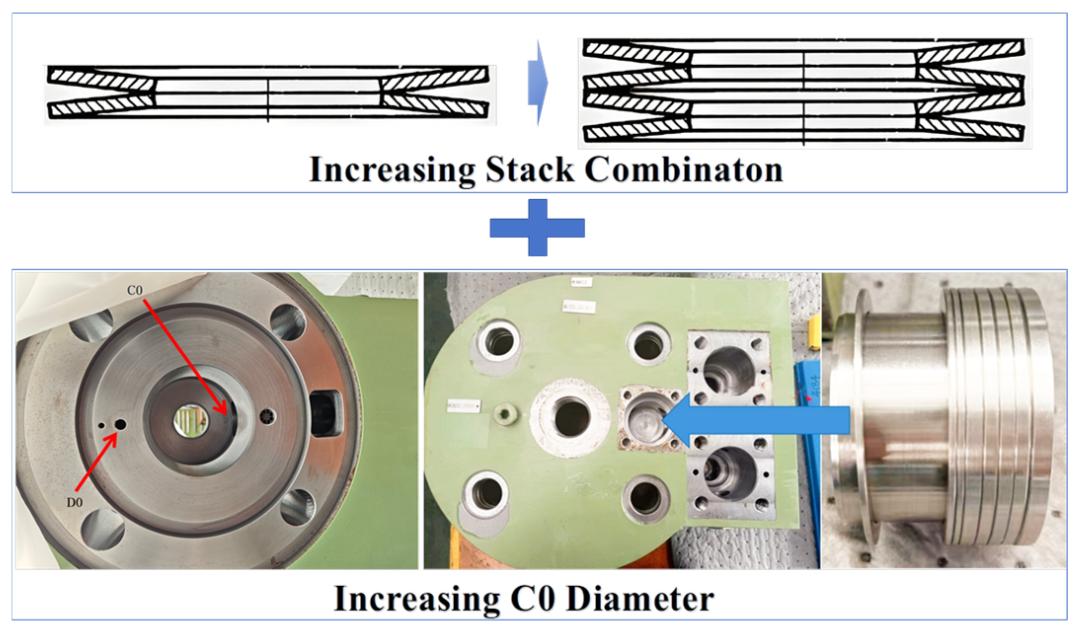
The above analysis indicates that closing timeout is mainly caused by insufficient spring driving force and excessive hydraulic resistance during pressure relief. To address these coupled causes, a coordinated optimization strategy combining coned-disc spring force compensation and hydraulic throttling parameter matching was proposed, as shown in
Figure 14. The effects of coned-disc spring force compensation and C0 throttling orifice adjustment were analyzed separately in
Section 4.2 and
Section 4.3. The combined optimization was then used to verify the practical correction effect under the coupled influence of spring driving force and hydraulic pressure-relief capacity, rather than to replace the individual sensitivity analysis.
In the engineering correction, one additional pair of coned-disc springs was installed, and the C0 throttling orifice diameter was increased by 4 mm. The C0 diameter was adjusted by changing the insertion depth of the throttling plug in the return-oil pipeline, as illustrated in
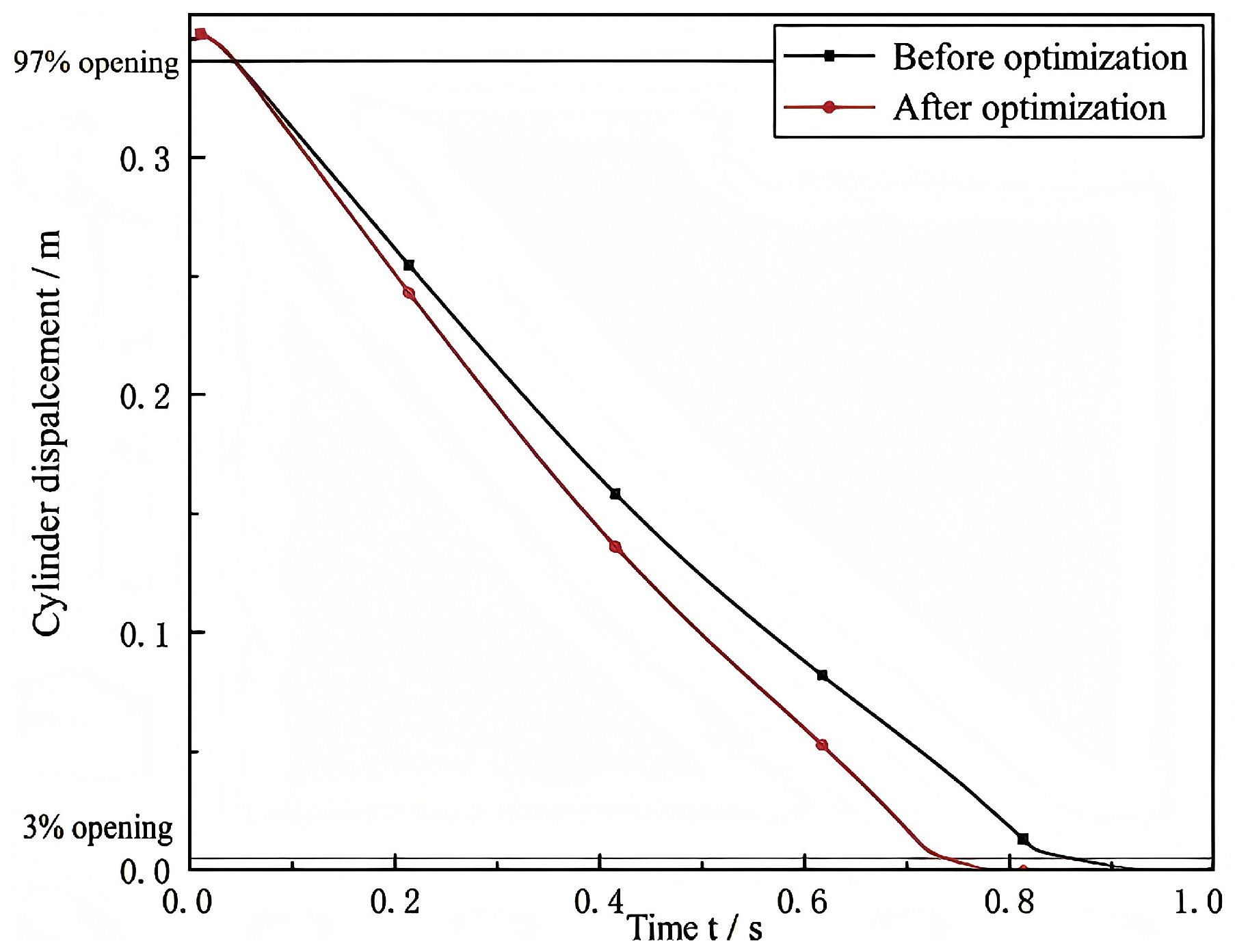
Figure 14. Changing the insertion depth modifies the effective flow area of the throttling passage and thereby regulates the return-flow capacity of the hydraulic circuit. As shown in
Figure 15, the coordinated correction significantly increased the actuator closing speed and reduced the fast-closing time to 0.78 s. The small-opening hysteresis was also alleviated, and the fast-closing performance satisfied the engineering requirement. Compared with the case in which only the C0 orifice was enlarged, the coordinated correction resulted in smoother terminal displacement variation and more stable end-force response, indicating that the C0 orifice effectively contributed to valve reseating cushioning.
It should be noted that the fast-closing time should not be reduced without limitation in engineering applications. For the investigated reheat-valve actuator, an excessively short closing time, especially below approximately 0.72 s, may lead to severe impact between the hydraulic cylinder piston and the cylinder end and may also increase the impact load on the butterfly-valve disc during reseating. Such an overly aggressive closing response is unfavourable for the long-term service life of the hydraulic actuator and valve components. Therefore, the practical optimization target is not to minimize the closing time, but to keep it within a strict engineering window that satisfies the upper limit of 0.8 s while avoiding excessive terminal impact.
The optimized fast-closing time of approximately 0.78 s falls within this acceptable range. Although the numerical margin relative to the 0.8 s requirement appears limited, the result represents a balanced engineering correction considering closing speed, hydraulic cushioning, terminal impact, and component durability. Further increasing the spring force or enlarging the C0 throttling orifice could shorten the closing time, but may also increase pressure fluctuation and valve reseating impact. In addition, the reheat-valve actuator is a complex sealed electro-hydraulic–mechanical system operating under long-term service conditions, and the internal states of many components are difficult to directly evaluate. A comprehensive reliability assessment considering manufacturing tolerances, component ageing, oil temperature variation, friction fluctuation, and operational uncertainties requires long-term degradation data and uncertainty modelling. This will be an important direction of our future work.
5. Conclusions
This study investigated the closing timeout problem of a nuclear reheat-valve oil-motor actuator system through coupled hydraulic–mechanical modelling, simulation analysis, and experimental validation. A dynamic model integrating the coned-disc spring assembly, hydraulic circuit, cartridge valve, gear–rack transmission, and load resistance was established to identify the dominant factors affecting fast-closing response.
The results show that coned-disc spring degradation is a major cause of closing timeout. The validated spring model agreed well with the experimental data, with an error below 0.5%. When the equivalent elastic modulus decreased from approximately 206 GPa to 195 GPa, the fast-closing time approached the critical limit of 0.8 s, and further degradation led to evident timeout. Increasing the parallel-stacking proportion improved the equivalent stiffness and closing driving force, thereby enhancing actuator response.
Hydraulic parameters also strongly influenced the closing process. The C0 throttling orifice governed the pressure-relief capacity of the working chamber and had the most direct effect on effective fast-closing time. Increasing its diameter accelerated pressure relief and shortened the closing time, but excessive enlargement may increase valve reseating impact and pressure fluctuation. Therefore, throttling parameters should be optimized by balancing closing speed, terminal cushioning, and system stability.
Based on this mechanism, an engineering correction strategy combining coned-disc spring force compensation and hydraulic parameter adjustment was proposed and verified. After adding one pair of coned-disc springs and increasing the C0 orifice diameter by 4 mm, the fast-closing time was reduced to approximately 0.78 s, meeting the engineering requirement, while small-opening hysteresis was effectively alleviated. This work provides practical guidance for timeout fault diagnosis, field commissioning, and optimization of nuclear reheat-valve oil-motor actuator systems.
Although this study was developed for a specific nuclear reheat-valve actuator, the proposed coupled hydraulic–mechanical modelling framework can be extended to other turbine valve systems with similar actuation principles. For different valve geometries or hydraulic layouts, the corresponding spring characteristics, hydraulic parameters, transmission relationship, and load-resistance model should be redefined. However, the specific optimization strategy cannot be directly transferred without recalibration, because the allowable closing time window, terminal impact constraint, and dominant sensitive parameters may vary among systems. Therefore, the proposed method provides a general analysis framework, while system-specific parameter identification and validation remain necessary for practical application.