Principle and Method of Base Station Calibration Based on a Physical Standard for Multi-Station Laser Tracking Measurement

 , , and
Abstract
1. Introduction
2. Materials and Methods
2.1. Principle of Spatial Coordinate Calculation Using Multilateration
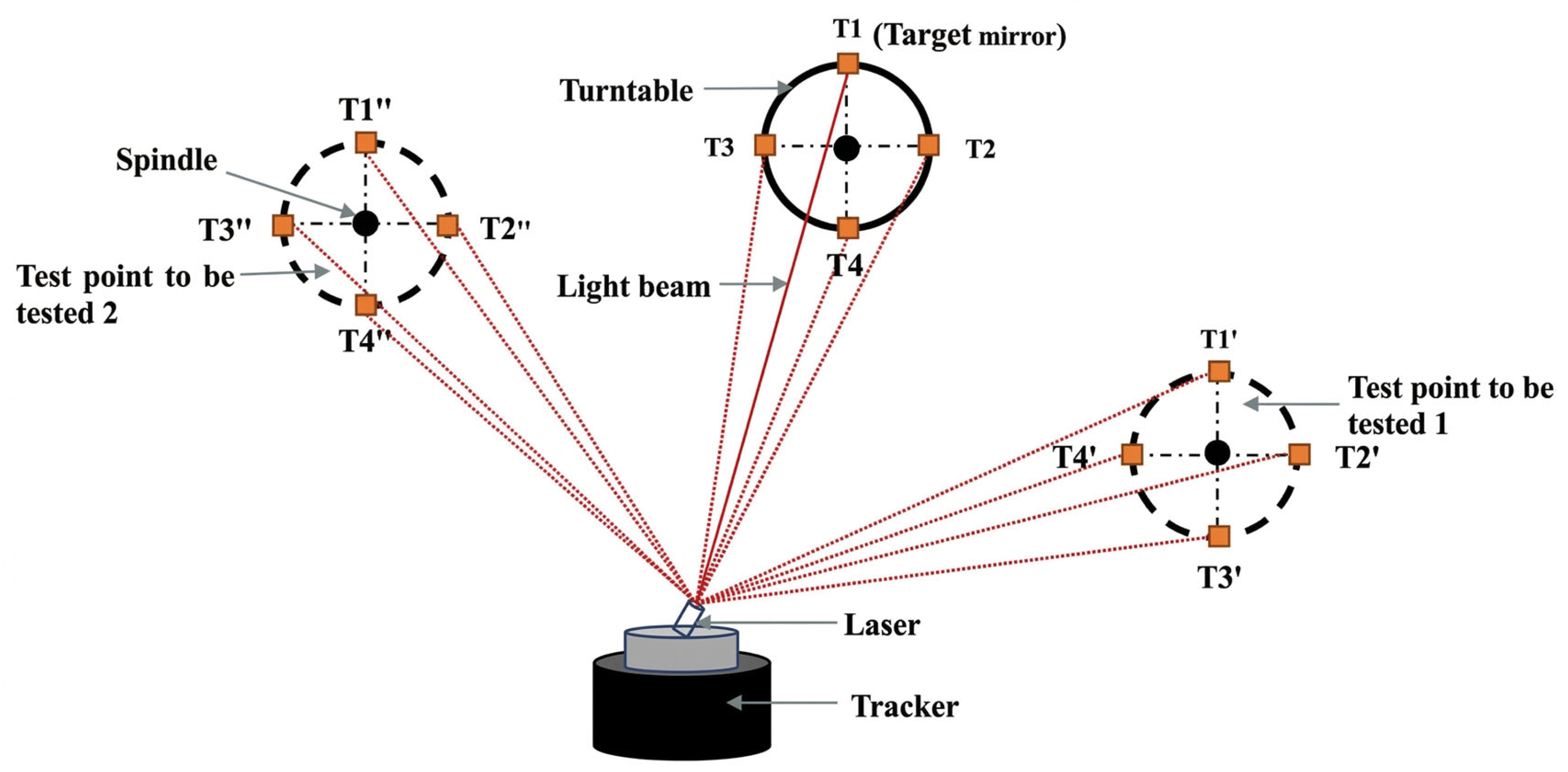
2.2. Principles of Base Station Calibration and Machine Tool Error Separation
3. Working Principle and Structural Design of the Base Station Calibrator
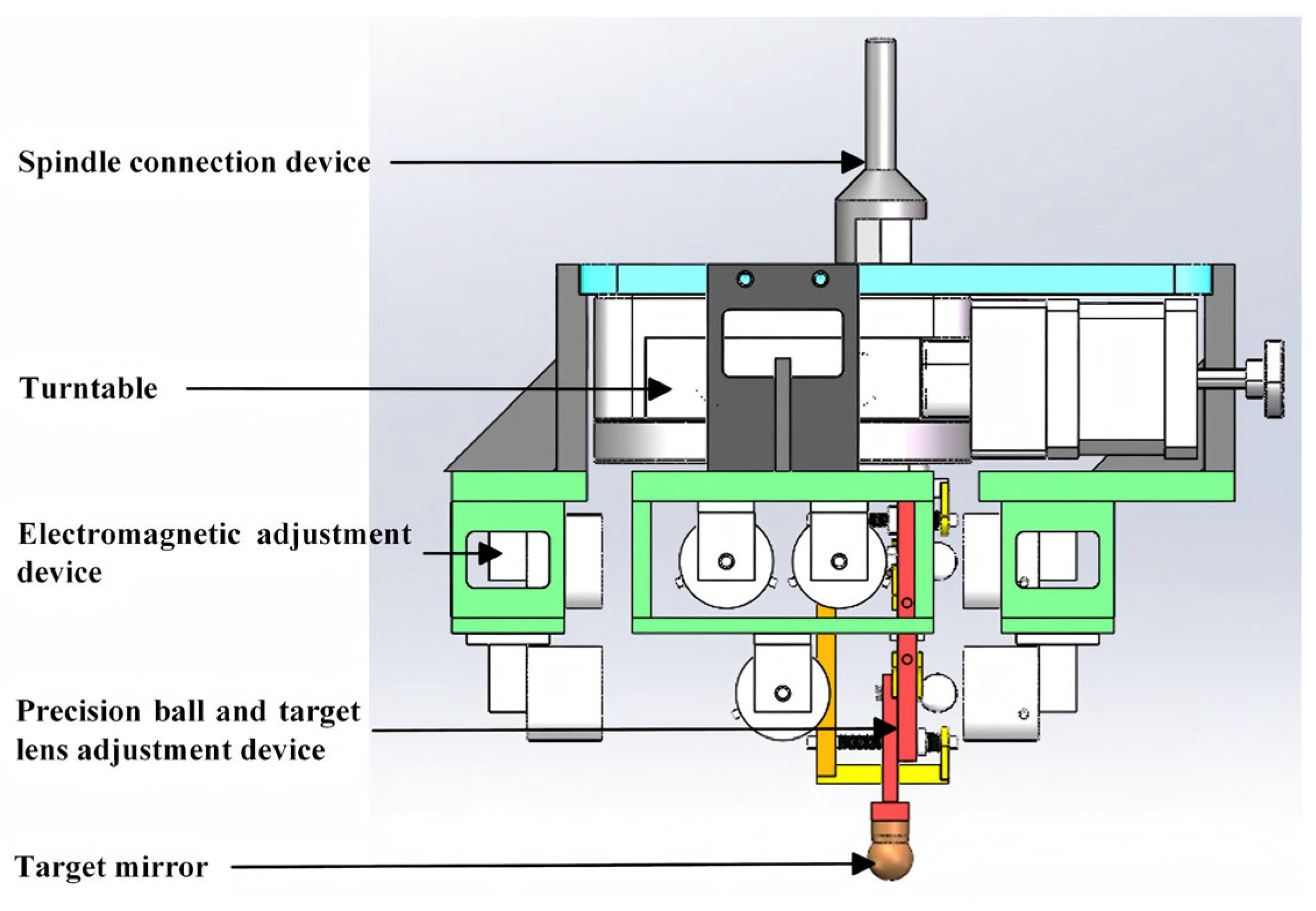
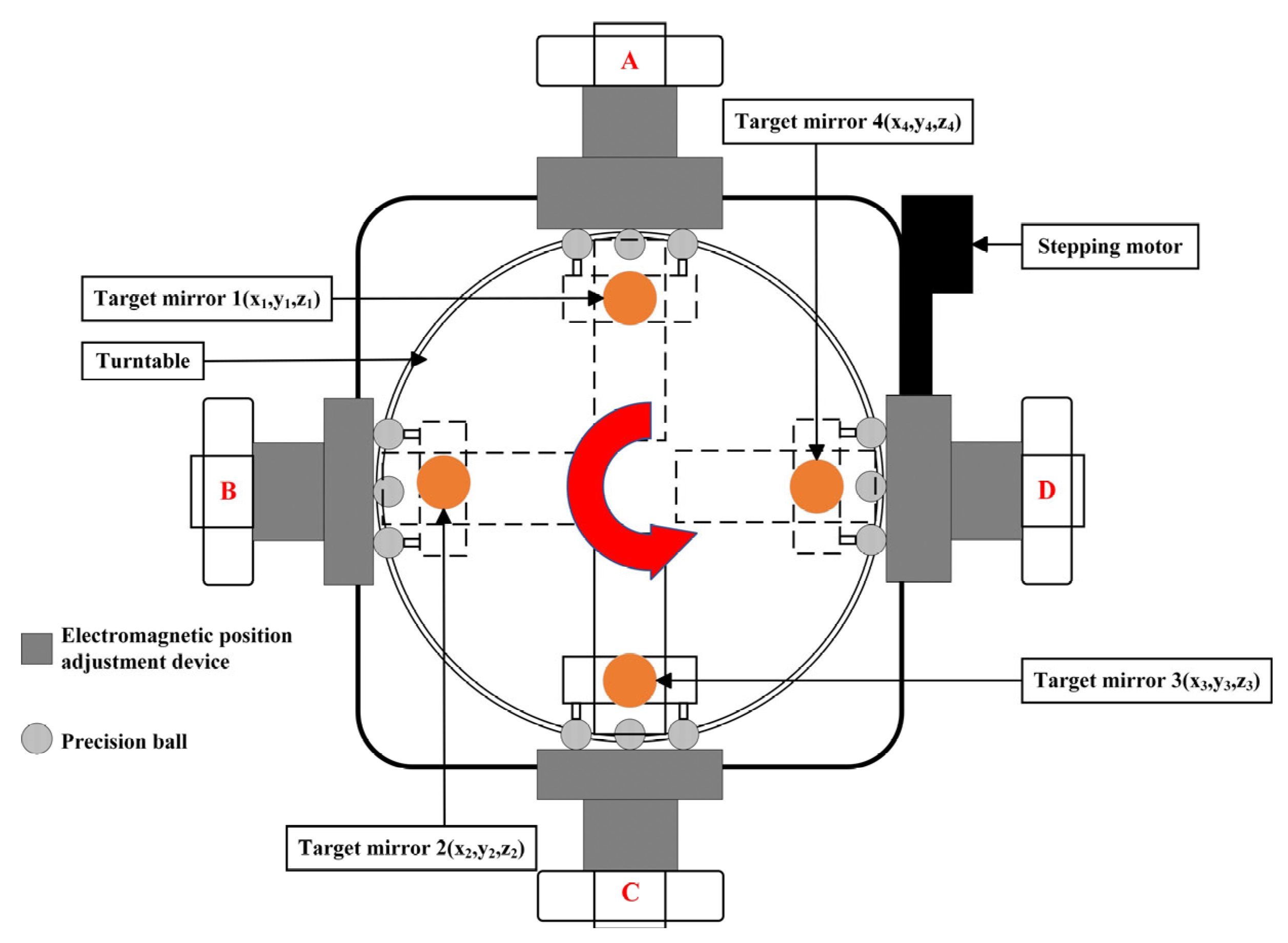
3.1. Overall Structural Design of the Base Station Calibrator
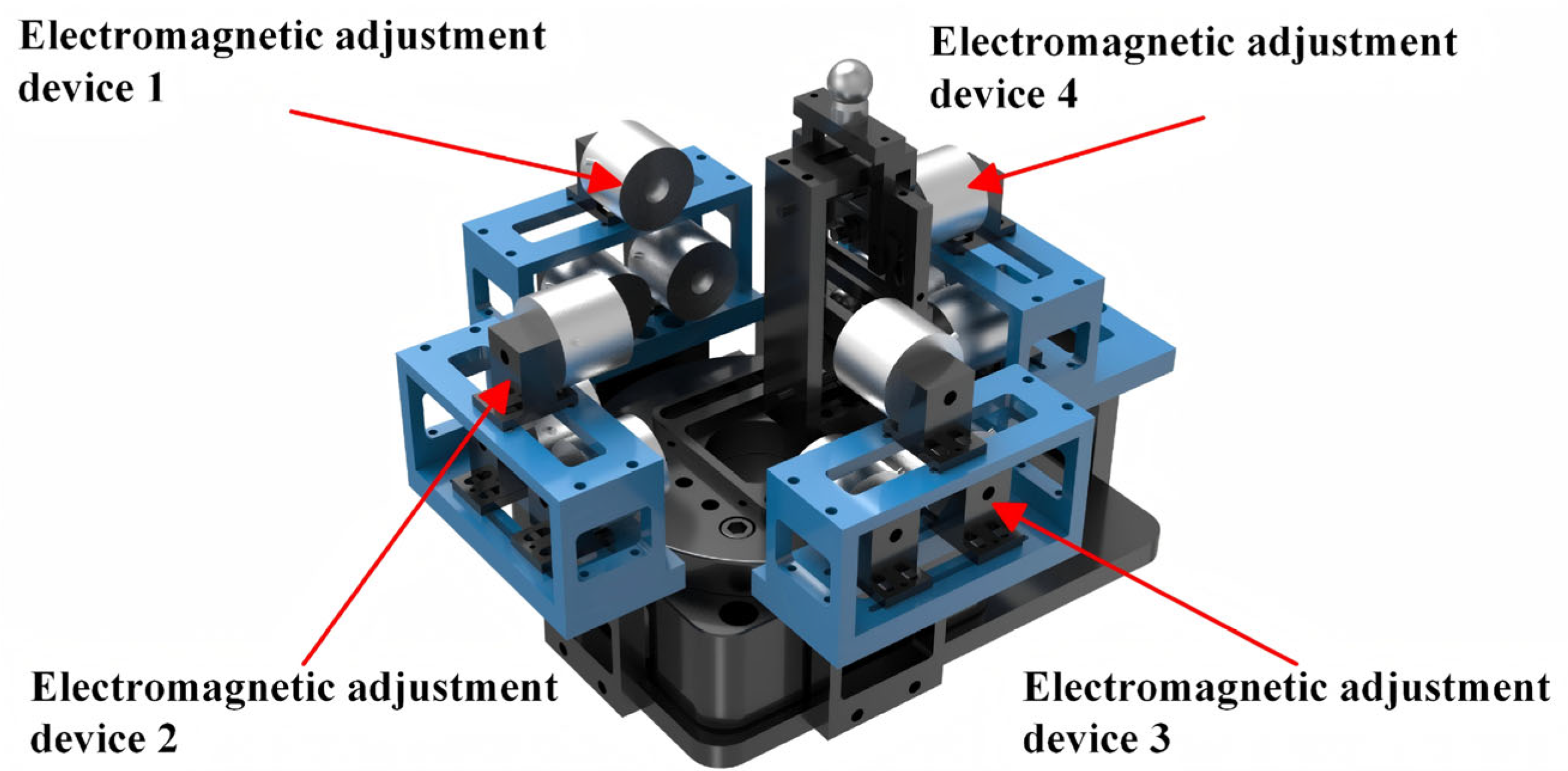
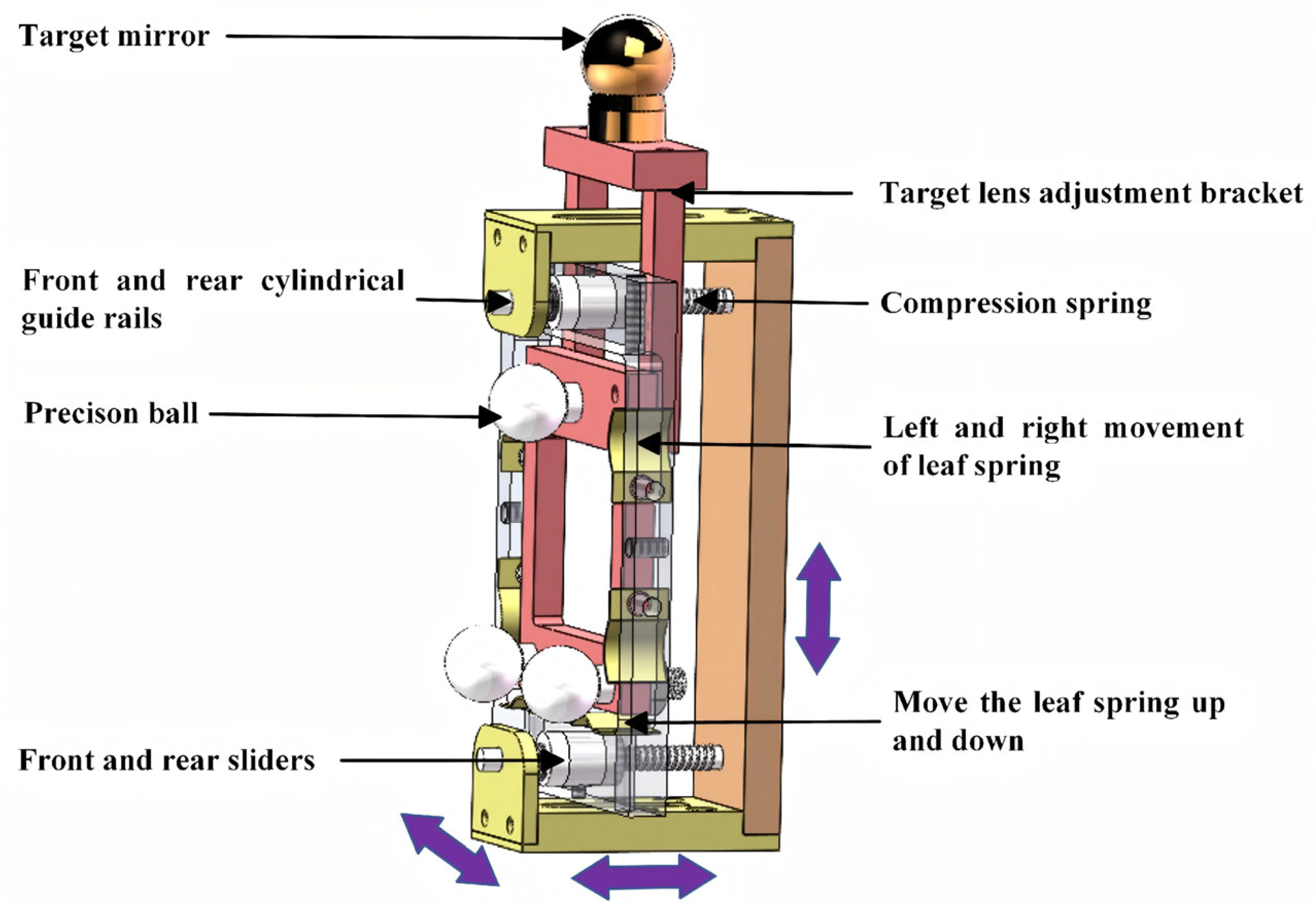
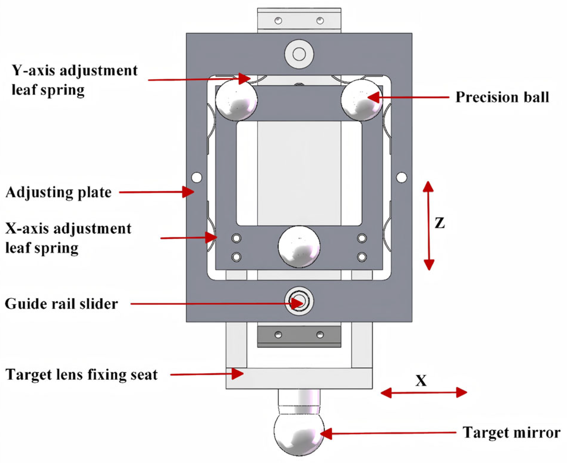
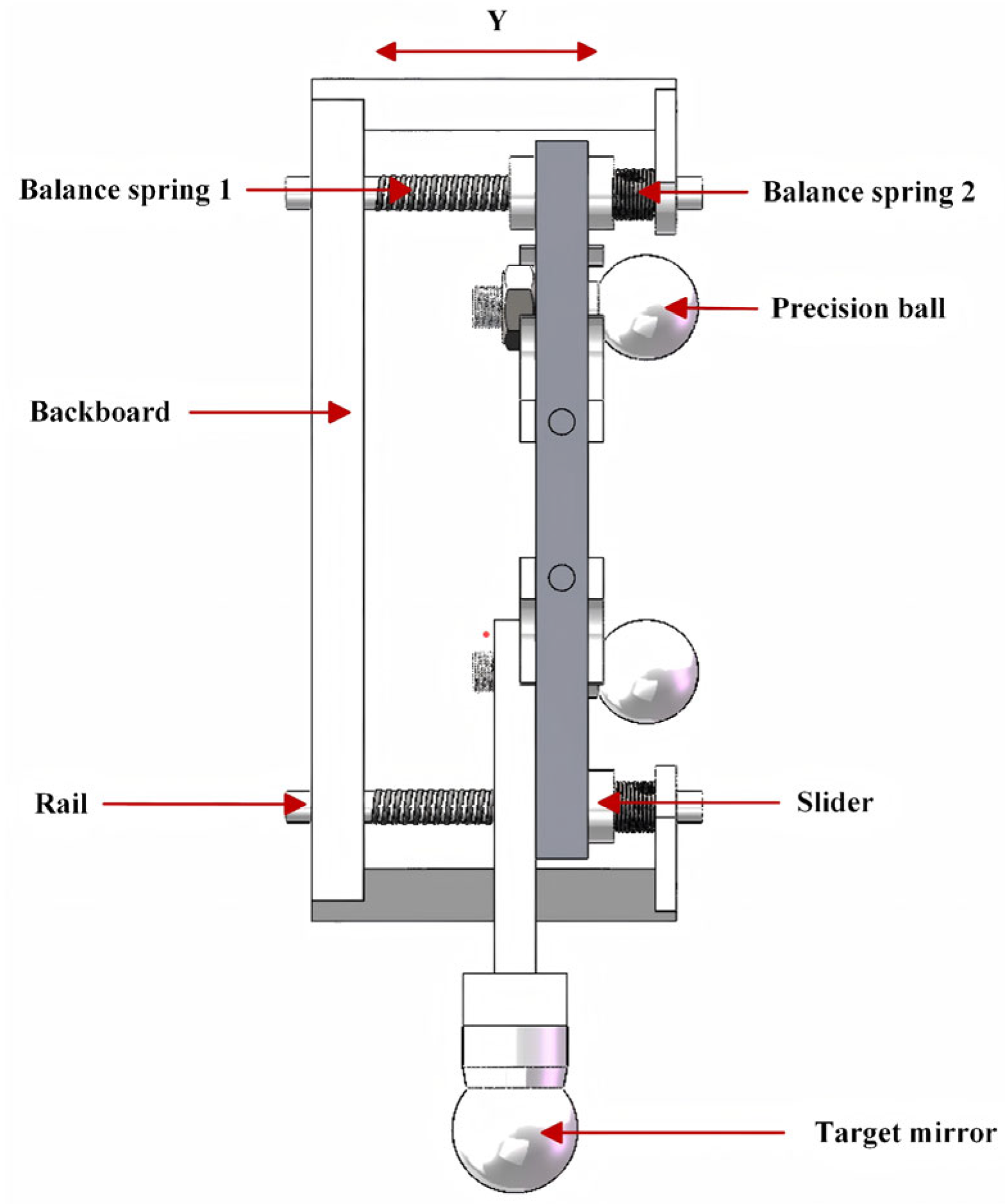
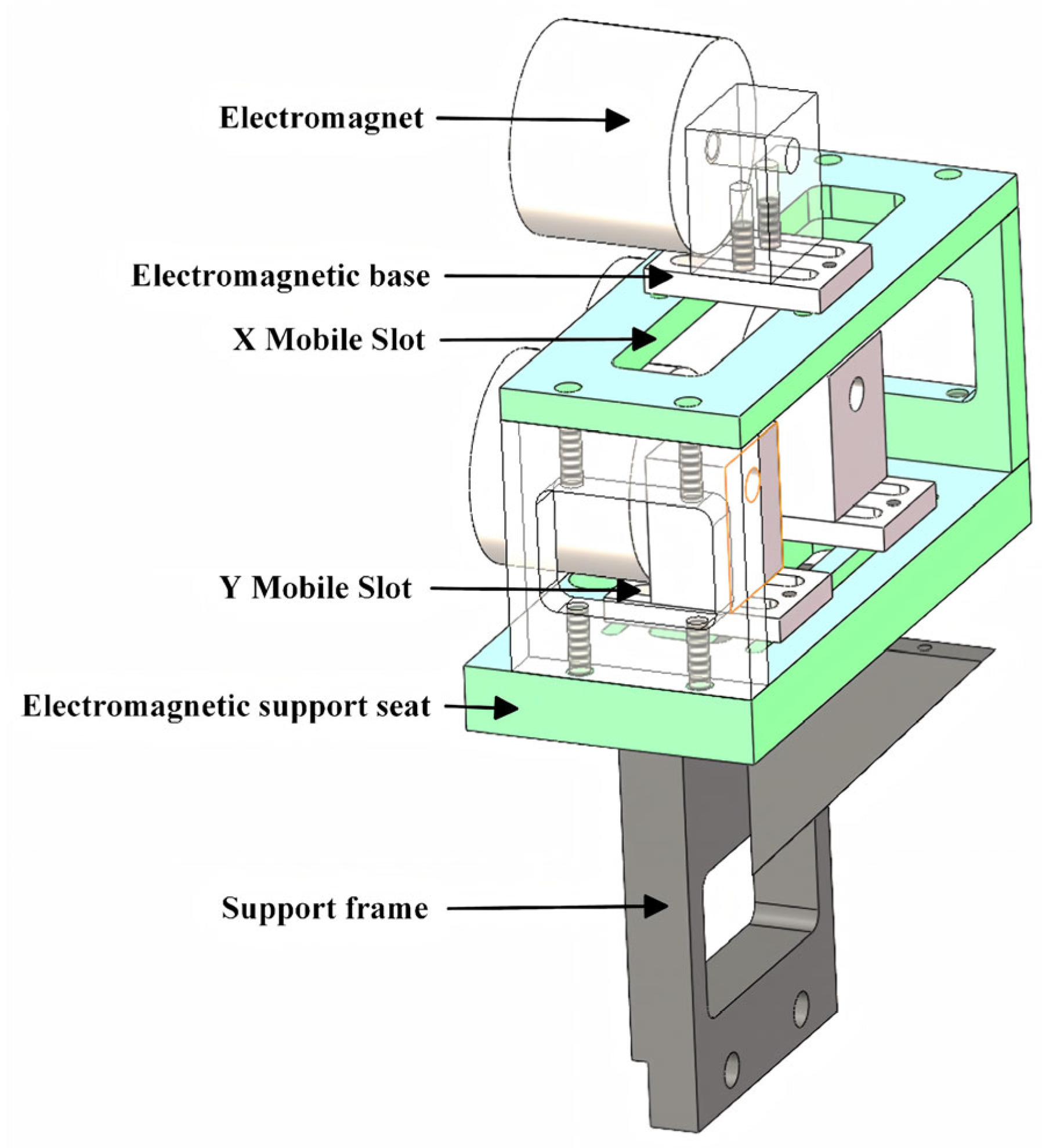
3.2. Target Mirror Adjustment Device and Electromagnet Adjustment Bracket
4. Target Mirror Position Calibration Experiment of the Base Station Calibrator
5. Experimental Measurement of Machine Tool Errors Based on the Base Station Calibrator
6. Conclusions
Author Contributions
Funding
Data Availability Statement
Conflicts of Interest
Abbreviations
| CNC | Computer Numerical Control |
| CMM | Coordinate Measuring Machine |
| 6-DOF | Six Degrees of Freedom |
| 3-DOF | Three Degrees of Freedom |
| 2-DOF | Two Degrees of Freedom |
References
- Schwenke, H.; Knapp, W.; Galetto, M.; Kunzmann, H.; Robertot, J.P.; Vischer, C.; Weikert, S. Geometric error measurement and compensation of machines—An update. CIRP Ann. 2008, 57, 660–675. [Google Scholar] [CrossRef]
- Lasemi, A.; Xue, D.; Gu, P. Recent development in CNC machining of freeform surfaces: A state-of-the-art review. Comput.-Aided Des. 2010, 42, 641–654. [Google Scholar] [CrossRef]
- Geng, Z.; Tong, Z.; Jiang, X. Review of geometric error measurement and compensation techniques of ultra-precision machine tools. Light Adv. Manuf. 2021, 2, 211–227. [Google Scholar] [CrossRef]
- Švéda, J.; Chládek, Š.; Hornych, T.; Kozlok, T.; Smolik, J. Increasing machining accuracy based on CNC machine tool correction data by using ad hoc modification. Machines 2022, 10, 288. [Google Scholar] [CrossRef]
- Zhao, Z.; Mao, J.; Wei, X. Geometric error-based multi-source error identification and compensation strategy for five-axis side milling. Machines 2024, 12, 340. [Google Scholar] [CrossRef]
- Xiang, S.; Altintas, Y. Modeling and compensation of volumetric errors for five-axis machine tools. Int. J. Mach. Tools Manuf. 2015, 101, 65–78. [Google Scholar] [CrossRef]
- Tian, A.; Liu, S.; Chen, K.; Mo, W.; Jin, S. Spatial expression of assembly geometric errors for multi-axis machine tool based on kinematic Jacobian-Torsor model. Chin. J. Mech. Eng. 2023, 36, 44. [Google Scholar] [CrossRef]
- Cui, G.; Lu, Y.; Li, J.; Gao, D.; Yao, Y. Geometric error compensation software system for CNC machine tools based on NC program reconstructing. Int. J. Adv. Manuf. Technol. 2012, 63, 169–180. [Google Scholar] [CrossRef]
- Givi, M.; Mayer, J.R.R. Validation of volumetric error compensation for a five-axis machine using surface mismatch producing tests and on-machine touch probing. Int. J. Mach. Tools Manuf. 2014, 87, 89–95. [Google Scholar] [CrossRef]
- Maeng, S.; Min, S. Simultaneous geometric error identification of rotary axis and tool setting in an ultra-precision 5-axis machine tool using on-machine measurement. Precis. Eng. 2020, 63, 94–104. [Google Scholar] [CrossRef]
- Ramesh, R.; Mannan, M.A.; Poo, A.N. Error compensation in machine tools—A review: Part I: Kinematic, geometric, and thermal errors. Int. J. Mach. Tools Manuf. 2000, 40, 1235–1256. [Google Scholar] [CrossRef]
- Holub, M.; Zatočilová, J.; Marek, T.; Blecha, P.; Heinrich, P. Numerical aspects of multilateration for volumetric error calculation. Machines 2022, 10, 833. [Google Scholar] [CrossRef]
- Hsu, C.-H.; Chen, J.-R.; Hsu, F.-H.; Chen, Y.-T. A novel measurement method for determining geometric errors of rotary tables by using LaserTRACER and reflectors. Appl. Sci. 2023, 13, 2419. [Google Scholar] [CrossRef]
- Schwenke, H.; Franke, M.; Hannaford, J.; Kunzmann, H. Error mapping of CMMs and machine tools by a single tracking interferometer. CIRP Ann. 2005, 54, 475–478. [Google Scholar] [CrossRef]
- Ibaraki, S.; Knapp, W. Indirect measurement of volumetric accuracy for three-axis and five-axis machine tools: A review. Int. J. Autom. Technol. 2012, 6, 110–124. [Google Scholar] [CrossRef]
- Egaña, F.; Mutilba, U.; Yagüe-Fabra, J.A.; Chekh, B.A.; Lopez, S. Generalising the machine tool integrated inverse multilateration method for the ambient thermal error analysis of large machine tools in industrial environments. Appl. Sci. 2025, 15, 2600. [Google Scholar] [CrossRef]
- Wang, J.; Chen, P.; Deng, Y.; Guo, J. New algorithms for motion error detection of numerical control machine tool by laser tracking measurement on the basis of GPS principle. Rev. Sci. Instrum. 2018, 89, 015104. [Google Scholar] [CrossRef]
- Sheng, Y.; Wang, Y.; Liu, S.; Wang, C.; Xi, J. Large-scale measurement layout optimization method based on laser multilateration. Machines 2022, 10, 988. [Google Scholar] [CrossRef]
- Haitao, L.; Xiaoning, J.; Yawen, W.; Lijun, Y.; Han, L.; Chenggong, Y.; Yuheng, Y.; Xinlei, G. A low-cost 3D dynamic measurement system for CNC machine tool geometric errors based on laser interferometry and dual-ballbar. Meas. Sci. Technol. 2025, 36, 095011. [Google Scholar] [CrossRef]
- Aguado, S.; Santolaria, J.; Samper, D.; Aguilar, J.J. Study of self-calibration and multilateration in machine tool volumetric verification for laser tracker error reduction. Proc. Inst. Mech. Eng. Part B J. Eng. Manuf. 2014, 228, 659–672. [Google Scholar] [CrossRef]
- Zha, J.; Zhang, H. Geometric error identification of gantry-type CNC machine tool based on multi-station synchronization laser tracers. Chin. J. Mech. Eng. 2024, 37, 46. [Google Scholar] [CrossRef]
- Zhu, S.; Ding, G.; Qin, S.; Lei, J.; Zhuang, L.; Yan, K. Integrated geometric error modeling, identification and compensation of CNC machine tools. Int. J. Mach. Tools Manuf. 2012, 52, 24–29. [Google Scholar] [CrossRef]
- Liu, X.; Xia, Y.; Rui, X. Uncertainty evaluation of multilateration-based geometric error measurement considering the repeatibility of positioning of the machine tool. Metrol. Meas. Syst. 2023, 30, 49–63. [Google Scholar] [CrossRef]
- Mutilba, U.; Gomez-Acedo, E.; Kortaberria, G.; Olarra, A.; Yagüe-Fabra, J.A. Traceability of on-machine tool measurement: A review. Sensors 2017, 17, 1605. [Google Scholar] [CrossRef] [PubMed]
- ISO 230-1:2012; Test Code for Machine Tools—Part 1: Geometric Accuracy of Machines Operating Under No-Load or Quasi-Static Conditions. International Organization for Standardization: Geneva, Switzerland, 2012.
- Ren, G.; Zhang, Y.; Li, H. Development and simulation of 3D laser telescoping ballbar. Mach. Tool Hydraul. 2021, 49, 105–109. (In Chinese) [Google Scholar]
- Liu, H.; Rasheed, M.; Su, M.; Liu, C.; Li, X. A new direct 9-line geometric error measurement method for CNC machine tools. IOP Conf. Ser. Mater. Sci. Eng. 2020, 790, 012174. [Google Scholar] [CrossRef]


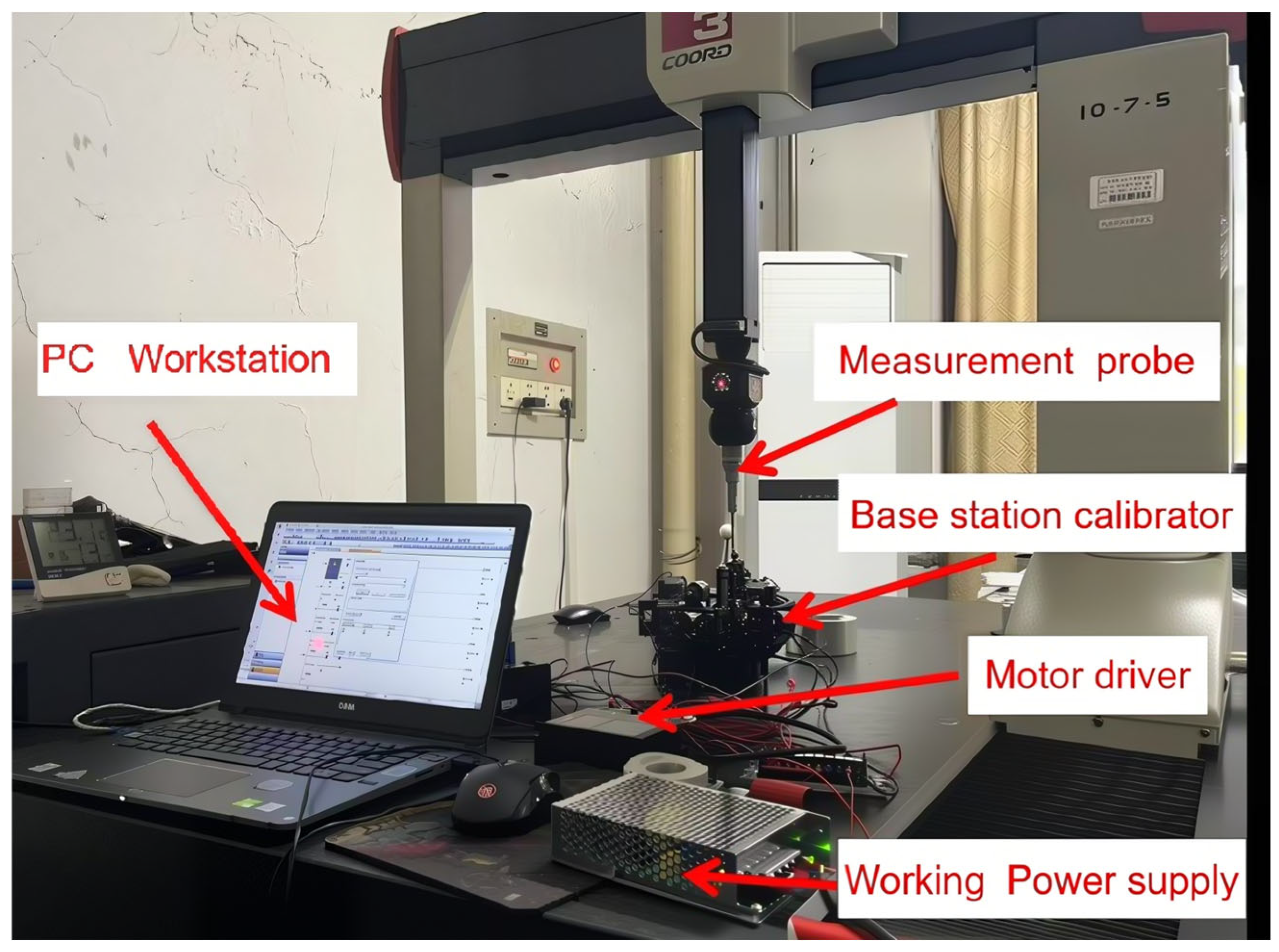





| Position A | Mean Value (mm) | Max (mm) | Min (mm) | Difference () | Standard Deviation (mm) |
|---|---|---|---|---|---|
| X | 383.3369 | 383.3375 | 383.3363 | 1.2 | 0.00189 |
| Y | 335.6237 | 335.6242 | 335.6231 | 1.1 | 0.00148 |
| Z | 112.3574 | 112.3581 | 112.3568 | 1.3 | 0.00153 |
| Position B | Mean Value (mm) | Max (mm) | Min (mm) | Difference () | Standard Deviation (mm) |
|---|---|---|---|---|---|
| X | 356.8247 | 356.8253 | 356.8242 | 1.1 | 0.00169 |
| Y | 361.7155 | 361.7163 | 361.7149 | 1.4 | 0.00170 |
| Z | 112.3388 | 112.3394 | 112.3381 | 1.3 | 0.00134 |
| Position C | Mean Value (mm) | Max (mm) | Min (mm) | Difference () | Standard Deviation (mm) |
|---|---|---|---|---|---|
| X | 331.7053 | 331.7061 | 331.7047 | 1.4 | 0.00156 |
| Y | 334.5298 | 334.5304 | 334.5291 | 1.3 | 0.00161 |
| Z | 112.3804 | 112.3811 | 112.3798 | 1.3 | 0.00142 |
| Position D | Mean Value (mm) | Max (mm) | Min (mm) | Difference () | Standard Deviation (mm) |
|---|---|---|---|---|---|
| X | 357.5912 | 357.5916 | 357.5903 | 1.3 | 0.00117 |
| Y | 308.3845 | 308.3851 | 308.3839 | 1.2 | 0.00152 |
| Z | 112.3383 | 112.3389 | 112.3378 | 1.1 | 0.00134 |
| Position (mm) | 0 | 50 | 100 | 150 | 200 | 250 | 300 | |
|---|---|---|---|---|---|---|---|---|
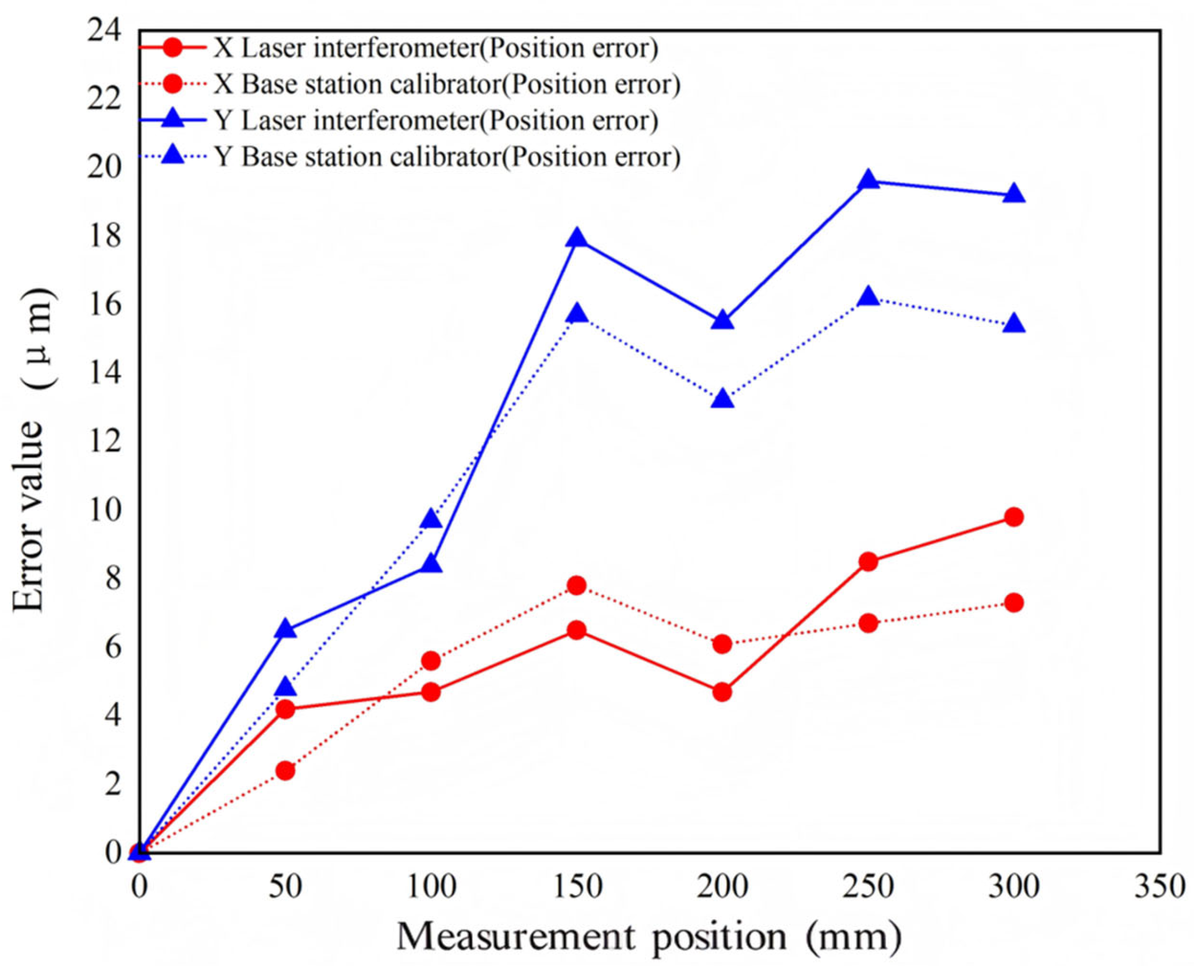
| Laser interferometer () | X axis | 0 | 4.2 | 4.7 | 6.5 | 4.7 | 8.5 | 9.8 |
| Y axis | 0 | 6.5 | 8.4 | 17.9 | 15.5 | 19.6 | 19.2 |
| Position (mm) | 0 | 50 | 100 | 150 | 200 | 250 | 300 | |
|---|---|---|---|---|---|---|---|---|
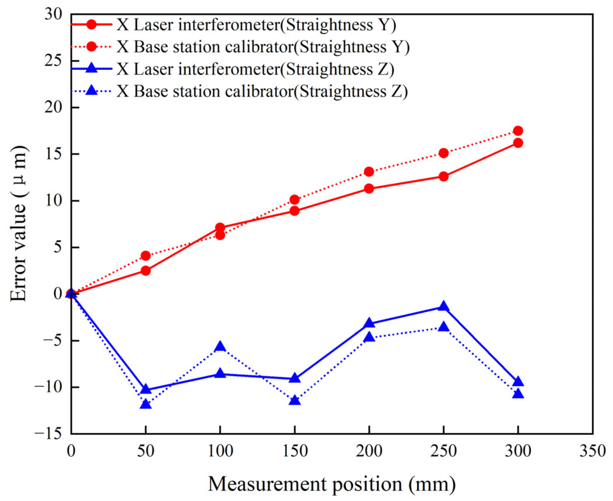
| Laser interferometer () | Y-directions | 0 | 2.5 | 7.1 | 8.9 | 11.3 | 12.6 | 16.2 |
| Z-directions | 0 | −10.3 | −8.6 | −9.1 | −3.2 | −1.4 | −9.5 |
| Position (mm) | 0 | 50 | 100 | 150 | 200 | 250 | 300 | |
|---|---|---|---|---|---|---|---|---|
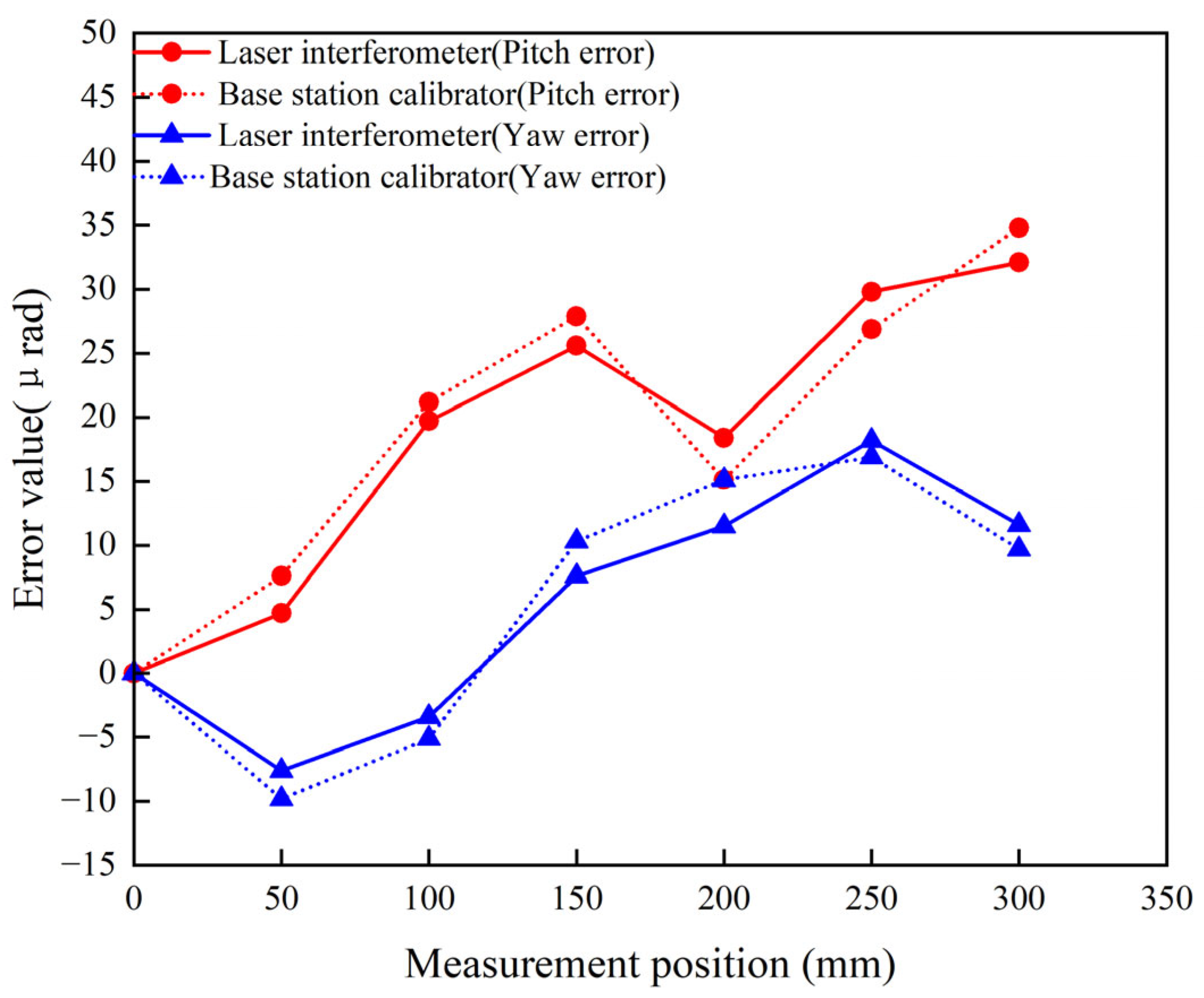
| Laser interferometer | pitch | 0 | 4.7 | 19.7 | 25.6 | 18.4 | 29.8 | 32.1 |
| yaw | 0 | −7.6 | −3.4 | 7.6 | 11.5 | 18.2 | 11.6 |
| Position (mm) | 0 | 50 | 100 | 150 | 200 | 250 | 300 | |
|---|---|---|---|---|---|---|---|---|
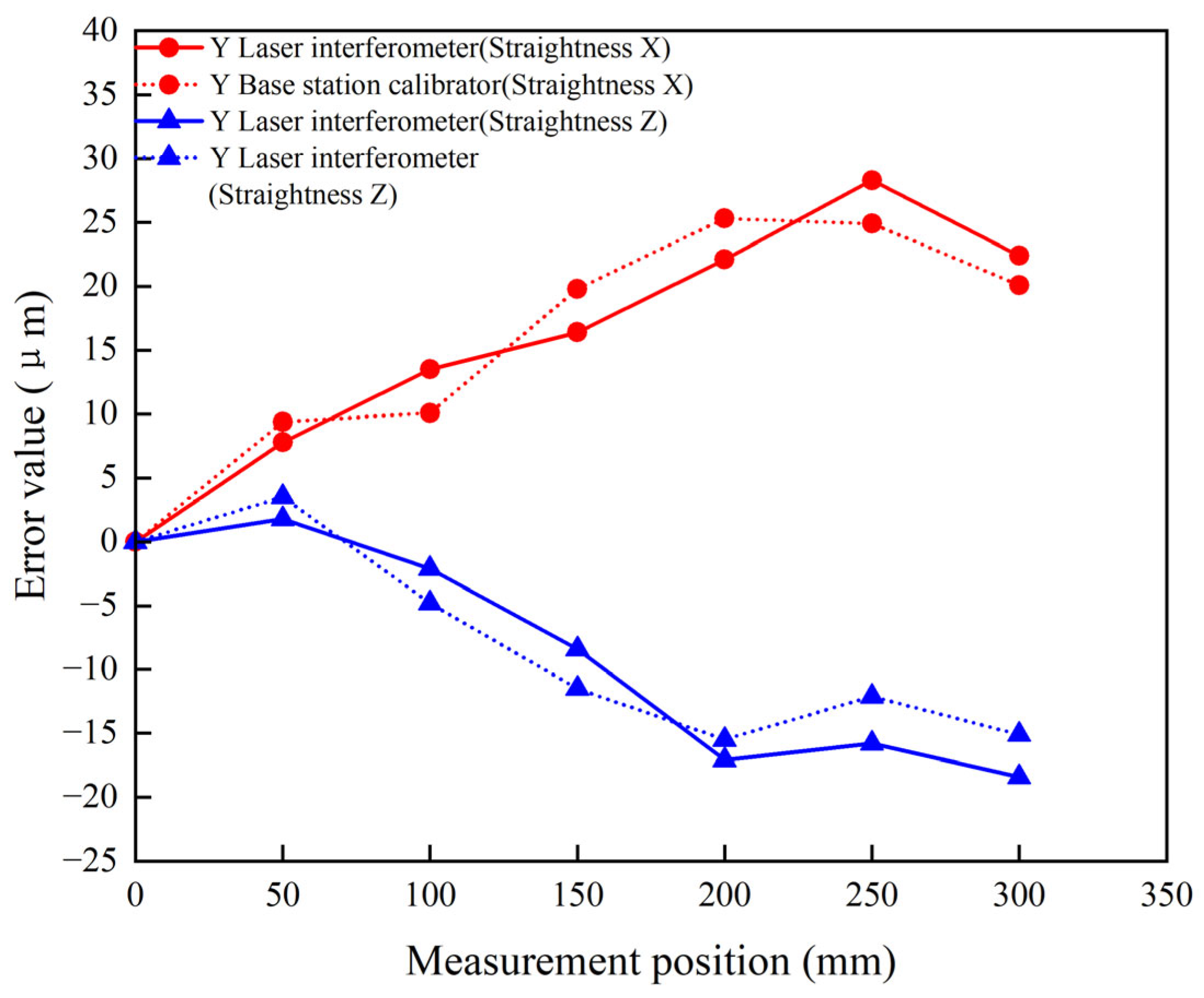
| Laser interferometer () | X-directions | 0 | 7.8 | 13.5 | 16.4 | 22.1 | 28.3 | 22.4 |
| Z-directions | 0 | 1.8 | −2.1 | −8.4 | −17.1 | −15.8 | −18.4 |
| Position (mm) | 0 | 50 | 100 | 150 | 200 | 250 | 300 | |
|---|---|---|---|---|---|---|---|---|
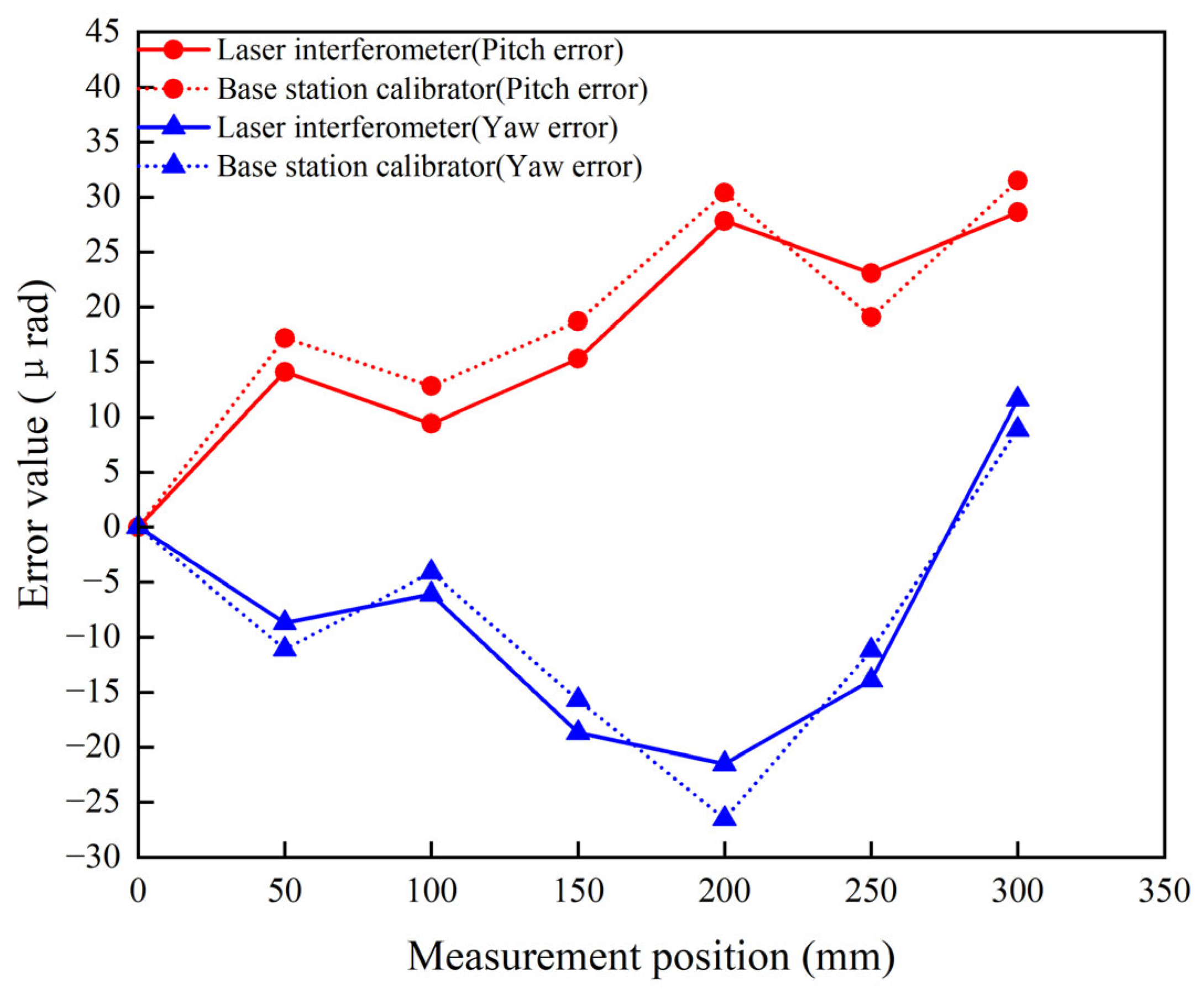
| Laser interferometer () | pitch | 0 | 14.1 | 9.4 | 15.3 | 27.8 | 23.1 | 28.6 |
| yaw | 0 | −8.7 | −6.1 | −18.7 | −21.5 | −13.9 | 11.6 |
| Measurement Location (mm) | 0 | 50 | 100 | 150 | 200 | 250 | 300 |
|---|---|---|---|---|---|---|---|
| Positioning error | 0 | 3.6 | 5.1 | 7.2 | 5.8 | 7.9 | 9.1 |
| Standard deviation | 0 | 0.93 | 1.03 | 1.51 | 1.11 | 1.06 | 0.98 |
| Straightness error Y | 0 | 4.1 | 6.3 | 10.1 | 13.2 | 15.1 | 17.5 |
| Standard deviation | 0 | 0.94 | 1.38 | 1.67 | 0.80 | 1.31 | 2.32 |
| Straightness error Z | 0 | −11.9 | −5.7 | −11.5 | −4.7 | −3.6 | −10.8 |
| Standard deviation | 0 | 1.39 | 1.66 | 1.55 | 0.74 | 0.99 | 0.87 |
| Pitch error | 0 | 7.6 | 21.2 | 27.9 | 15.1 | 26.9 | 34.8 |
| Standard deviation | 0 | 0.88 | 1.28 | 1.38 | 1.14 | 1.36 | 1.45 |
| Yaw error | 0 | −9.8 | −5.1 | 10.3 | 15.1 | 16.9 | 9.7 |
| Standard deviation | 0 | 1.13 | 0.78 | 1.57 | 1.09 | 0.93 | 1.16 |
| Measurement Location (mm) | 0 | 50 | 100 | 150 | 200 | 250 | 300 |
|---|---|---|---|---|---|---|---|
| Positioning error | 0 | 5.6 | 8.6 | 16.5 | 14.6 | 18.3 | 17.7 |
| Standard deviation | 0 | 1.5 | 1.11 | 1.34 | 1.16 | 1.36 | 1.25 |
| Straightness error Y | 0 | 9.4 | 10.1 | 19.8 | 25.3 | 24.9 | 20.1 |
| Standard deviation | 0 | 1.22 | 1.88 | 1.15 | 1.43 | 1.36 | 1.25 |
| Straightness error Z | 0 | 3.5 | −4.8 | −11.5 | −15.5 | −12.1 | −15.1 |
| Standard deviation | 0 | 1.13 | 1.41 | 1.66 | 1.3 | 2.11 | 1.03 |
| Pitch error | 0 | 17.2 | 12.8 | 18.7 | 30.4 | 19.1 | 31.5 |
| Standard deviation | 0 | 1.28 | 1.26 | 2.22 | 1.60 | 2.15 | 2.61 |
| Yaw error | 0 | −11.1 | −4.1 | −15.7 | −26.5 | −11.2 | 8.9 |
| Standard deviation | 0 | 1.54 | 1.43 | 1.32 | 1.70 | 1.48 | 1.53 |
| Time () | Ambient Temperature () | Near-Spindle Temperature () |
|---|---|---|
| 0 | 19.0 | 19.3 |
| 0.5 | 19.2 | 19.6 |
| 1.0 | 19.5 | 19.9 |
| 1.5 | 19.7 | 20.3 |
| 2.0 | 20.0 | 20.5 |
| 2.5 | 20.4 | 21.0 |
| Frequency () | Acceleration Amplitude () | Illustrate |
|---|---|---|
| 50 | 0.6 | Power supply low frequency interference |
| 120 | 1.2 | Spindle motor harmonics |
| 260 | 2.0 | Tool cycle vibration peak value |
| 400–700 | 0.3–0.5 | Stray mechanical noise |
| Measurement Position (mm) | Standard Deviation () | Combined Standard Uncertainty () | Expanded Uncertainty (k = 2) () |
|---|---|---|---|
| 0 | 0.00 | 0.56 | 1.28 |
| 50 | 1.00 | 1.22 | 2.44 |
| 100 | 1.05 | 1.26 | 2.52 |
| 150 | 1.59 | 1.73 | 3.46 |
| 200 | 1.22 | 1.40 | 2.80 |
| 250 | 1.21 | 1.39 | 2.78 |
| 300 | 1.03 | 1.24 | 2.48 |
| Measurement Position (mm) | Standard Deviation () | Combined Standard Uncertainty () | Expanded Uncertainty (k = 2) () |
|---|---|---|---|
| 0 | 0.00 | 0.57 | 1.32 |
| 50 | 0.93 | 1.15 | 2.30 |
| 100 | 1.54 | 1.70 | 3.40 |
| 150 | 1.76 | 1.88 | 3.76 |
| 200 | 1.16 | 1.36 | 2.72 |
| 250 | 1.34 | 1.50 | 3.00 |
| 300 | 1.55 | 1.71 | 3.42 |
| Measurement Position (mm) | Standard Deviation () | Combined Standard Uncertainty () | Expanded Uncertainty (k = 2) () |
|---|---|---|---|
| 0 | 0.00 | 0.64 | 1.45 |
| 50 | 1.18 | 1.36 | 2.72 |
| 100 | 1.71 | 1.85 | 3.70 |
| 150 | 1.68 | 1.83 | 3.66 |
| 200 | 0.88 | 1.12 | 2.24 |
| 250 | 1.06 | 1.26 | 2.52 |
| 300 | 1.05 | 1.25 | 2.50 |
| Measurement Position (mm) | Standard Deviation () | Combined Standard Uncertainty () | Expanded Uncertainty (k = 2) () |
|---|---|---|---|
| 0 | 0.00 | 0.47 | 1.21 |
| 50 | 1.62 | 1.69 | 3.38 |
| 100 | 1.32 | 1.39 | 2.78 |
| 150 | 1.87 | 1.94 | 3.88 |
| 200 | 1.43 | 1.50 | 3.00 |
| 250 | 1.49 | 1.57 | 3.14 |
| 300 | 1.18 | 1.26 | 2.52 |
| Measurement Position (mm) | Standard Deviation () | Combined Standard Uncertainty () | Expanded Uncertainty (k = 2) () |
|---|---|---|---|
| 0 | 0.00 | 0.63 | 1.12 |
| 50 | 1.24 | 1.33 | 2.66 |
| 100 | 1.27 | 1.35 | 2.70 |
| 150 | 1.55 | 1.63 | 3.26 |
| 200 | 1.13 | 1.22 | 2.44 |
| 250 | 1.16 | 1.25 | 2.50 |
| 300 | 1.22 | 1.31 | 2.62 |
| Error Term | Positioning Error | Straightness Error (X) | Straightness Error (Z) | Pitch Error |
|---|---|---|---|---|
| Measuring range | 0–300 mm | 0–300 mm | 0–300 mm | 0–300 mm |
| Standard deviation | 1.11–1.5 | 1.15–1.88 | 1.03–2.11 | 1.26–2.60 |
| Combined standard uncertainty | 1.57–1.94 | 1.44–2.20 | 1.40–2.37 | 1.39–2.67 |
| Expanded uncertainty (k = 2) | 3.14–3.88 | 2.88–4.40 | 2.8–4.74 | 2.78–5.34 |
Disclaimer/Publisher’s Note: The statements, opinions and data contained in all publications are solely those of the individual author(s) and contributor(s) and not of MDPI and/or the editor(s). MDPI and/or the editor(s) disclaim responsibility for any injury to people or property resulting from any ideas, methods, instructions or products referred to in the content. |
© 2026 by the authors. Licensee MDPI, Basel, Switzerland. This article is an open access article distributed under the terms and conditions of the Creative Commons Attribution (CC BY) license.
Share and Cite
Li, H.; Wang, Y.; Wang, Y.; Yu, Y.; Wang, Z.; Su, W.; Zhu, Y.; Yang, L.; Ma, C.; Li, J.; et al. Principle and Method of Base Station Calibration Based on a Physical Standard for Multi-Station Laser Tracking Measurement. Machines 2026, 14, 614. https://doi.org/10.3390/machines14060614
Li H, Wang Y, Wang Y, Yu Y, Wang Z, Su W, Zhu Y, Yang L, Ma C, Li J, et al. Principle and Method of Base Station Calibration Based on a Physical Standard for Multi-Station Laser Tracking Measurement. Machines. 2026; 14(6):614. https://doi.org/10.3390/machines14060614
Chicago/Turabian StyleLi, Haitao, Yuanbiao Wang, Yawen Wang, Yunlong Yu, Zehao Wang, Weihao Su, Yehao Zhu, Lijun Yang, Chi Ma, Jie Li, and et al. 2026. "Principle and Method of Base Station Calibration Based on a Physical Standard for Multi-Station Laser Tracking Measurement" Machines 14, no. 6: 614. https://doi.org/10.3390/machines14060614
APA StyleLi, H., Wang, Y., Wang, Y., Yu, Y., Wang, Z., Su, W., Zhu, Y., Yang, L., Ma, C., Li, J., & Zhang, M. (2026). Principle and Method of Base Station Calibration Based on a Physical Standard for Multi-Station Laser Tracking Measurement. Machines, 14(6), 614. https://doi.org/10.3390/machines14060614