Article

Design Analysis and Comparison of a Novel IPM Synchronous Machine with Minimum Rare-Earth PM Usage for EV Industrial Applications

by
Wasiq Ullah
1,*,
Mehroz Fatima
2,
Mohammad A. Abido
3,
Udochukwu B. Akuru
4,
Husam S. Samkari
5,6,
Mohammed F. Allehyani
5 and
Abdul Khalique Junejo
3
1
Department of Electrical Engineering, Kabul Polytechnic University, Kabul 1001, Afghanistan
2
Department of Electrical Power Engineering & Mechatronics, Tallinn University of Technology, 19086 Tallinn, Estonia
3
Interdisciplinary Research Center for Sustainable Energy Systems, King Fahd University of Petroleum & Minerals, Dhahran 31261, Saudi Arabia
4
Department of Electrical Engineering, Tshwane University of Technology, Pretoria 0183, South Africa
5
Department of Electrical Engineering, University of Tabuk, Tabuk 47713, Saudi Arabia
6
Artificial Intelligence and Sensing Technologies Research Center, University of Tabuk, Tabuk 47713, Saudi Arabia
*
Author to whom correspondence should be addressed.
Machines 2026, 14(5), 530; https://doi.org/10.3390/machines14050530
Submission received: 30 March 2026 / Revised: 1 May 2026 / Accepted: 8 May 2026 / Published: 9 May 2026
(This article belongs to the Section Electrical Machines and Drives)

Abstract

Due to the widespread adoption of high-performance electric vehicles (EVs), Interior Permanent Magnet (IPM) machines have achieved significant advancement in the field of electric motors due to their high torque density and efficiency. However, research has been ongoing for many decades to suppress the rare-earth permanent magnet (PM) usage without sacrificing electromagnetic performance while still achieving the required torque, power, and efficiency. In this regard, various EV manufacturers, such as Honda, Toyota, Chevrolet, BMW, and Nissan, have developed different types of IPM topologies; however, the rare-earth PM usage is extensively high, and the torque density is lower. Thus, to reduce the PM consumption and improve the electromagnetic performance, especially torque density, this paper proposes a novel segmented delta-shaped IPM (SΔ-IPM) with a three-notched rotor pole shape having two different specifications and featuring embedded circular flux barriers and an intermediate flux bridge. Secondly, torque performance is analytically discussed, and electromagnetic performance has been evaluated using 2D finite element analysis (FEA). Due to its unique design featuring improved magnetic field shifting, an average torque of 393.7 Nm with torque ripples of 5.1% and a cogging torque of 0.57 Nm has been achieved. Finally, an extensive comparative analysis of the aforementioned ten state-of-the-art industry models has been conducted, which confirms the effectiveness of the proposed design for high torque density with minimum PM usage.

1. Introduction

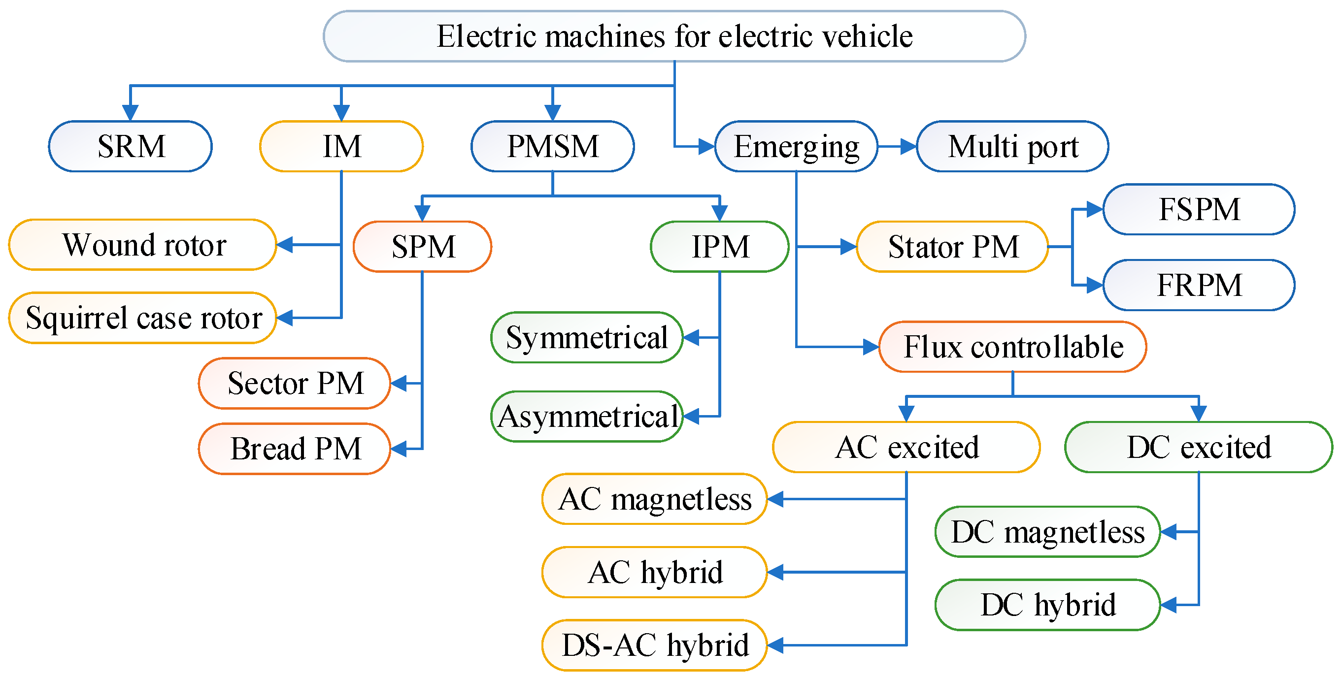
Electric vehicle (EV) and hybrid EV (HEV) technologies and applications have become more accessible due to the rapid growth of electric machines and drive systems over the last few years [1]. The power densities for electric machine drive systems are now on par with or even higher than those of current internal combustion engines (ICEs). A general tree diagram of EV electric machine topologies is shown in Figure 1. Compared with other machine types, permanent-magnet (PM) machines now have the highest power density and efficiency. Based on where the PM is located within the machine, these machines are divided into rotor- and stator-PM machines. Additionally, there are four different types of rotor PM machines: surface-mounted, interior radial, surface-inset, and interior circumferential. Numerous studies have been conducted on the functionality, design, and control strategies of these machines [2,3,4,5].
IPM machines with high efficiency, high power density, and a broad, constant-power-speed range have been used in Toyota Prius and other HEV systems [6]. The structure and control of IPM machines have been examined in [7]. Due to their high torque density, easy heat dissipation, high robustness, and good resistance to centrifugal forces, stator-PM machines have rekindled interest. Stator PM machines, on the other hand, offer the benefits of high robustness, efficient heat dissipation, high torque density, and strong durability against centrifugal forces [8]. Flux-reversal PM (FRPM), doubly salient PM, and flux-switching PM (FSPM) machines are the three main categories of stator-PM machines [8,9,10]. However, the aforementioned cutting-edge electric machines are used only for research, whereas surface-mounted PM (SPM), interior PM (IPM), and permanent magnet synchronous machines (PMSMs) are extensively used in a variety of commercial automotive applications across various industries.
EVs and HEVs have been extensively studied due to increased concerns about energy issues and environmental degradation [11]. The design of their motors, particularly permanent-magnet motors, is a key innovation for EVs and HEVs. Due to their high torque density, high power density, and high efficiency, PM brushless motors have received the most attention among the numerous types of electric motors [12,13]. Due to their high torque density, high efficiency, and extended speed range, which are enabled by both PM and reluctance torque, interior permanent magnet (IPM) motors have attracted significant attention in the global push for sustainable transportation solutions [14,15] and the rapid development of electric vehicles [16].
Numerous rotor configurations of IPM machines are described in the literature, including bar-shaped [15], V-shaped [15,17,18], delta-shaped [18], double-V-shaped [19], and spoke-type [20] structures. The V-type IPM motor, which has been used in Prius models from 2004 to 2010 [21,22], has a higher saliency ratio and smaller PM losses than the flat-type motor, making it more suitable for high-speed applications. There have been numerous proposals to replace the V-type IPM motor. Due to its split-rotor structure, the spoke-type PM motor has a high PM material utilisation ratio but poor mechanical robustness [23,24].
The ferrite PM-assisted synchronous reluctance motor has been considered a potential replacement for the V-type IPM motor due to the high cost and erratic supply of rare-earth PMs [25,26]. Additionally, multi-layer rotor topologies have received extensive attention in research [27,28] and are frequently referred to as PM-aided synchronous reluctance machines. Additionally, substantial research has been conducted on delta-type IPM motors, in addition to V-type, double V-type, and spoke-type IPM motors [29]. The overall performance of the delta-type IPM is remarkable in terms of power density and torque ripple. Compared to a machine with a surface-mounted permanent magnet, the IPM machine offers higher salient reluctance torque [28]. Additionally, the delta-type IPMSG’s multi-layered permanent-magnet structure produces more reluctance torque than a single-layered one [30,31].
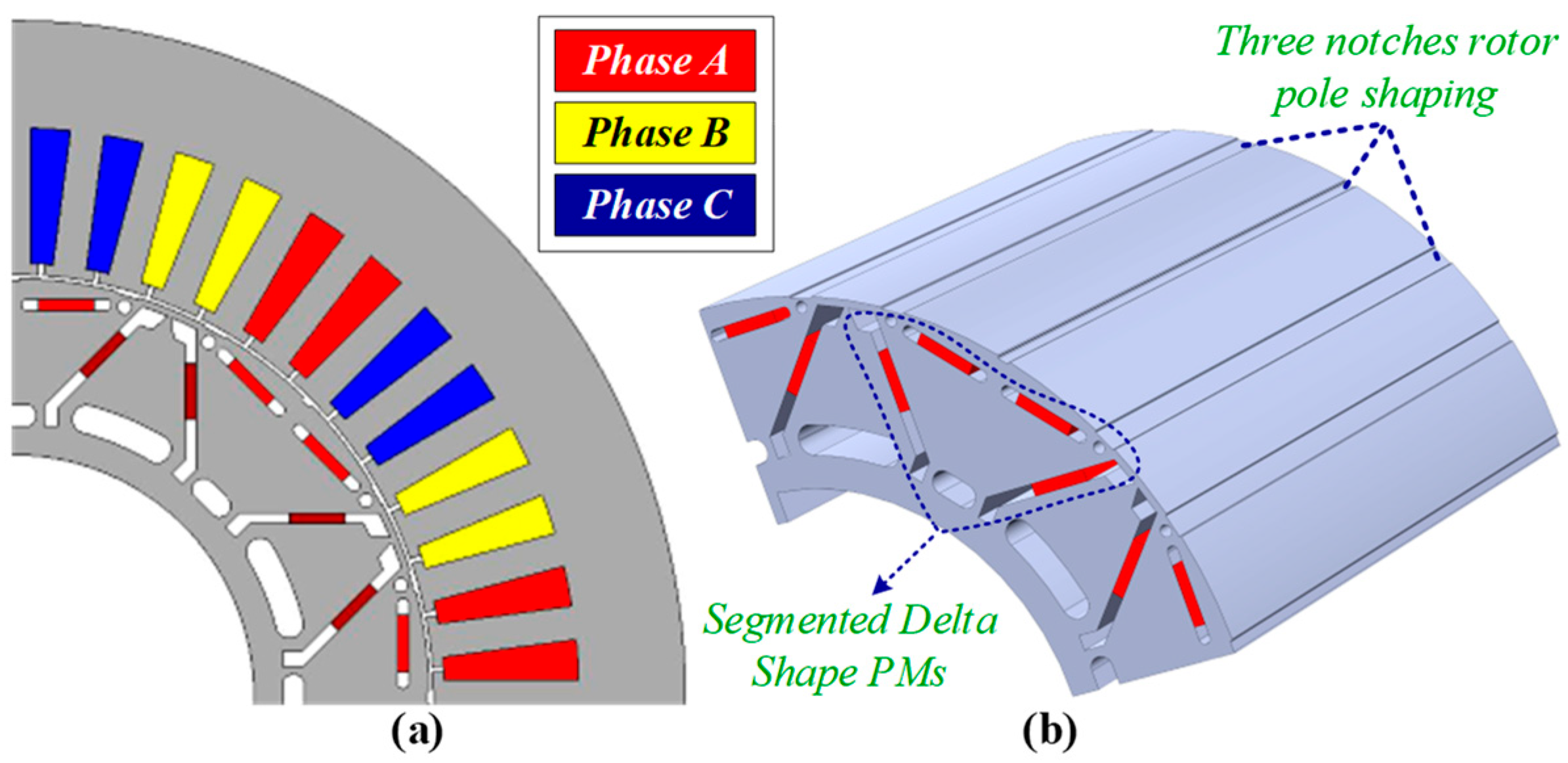
To improve the torque profile, torque density, torque-to-magnet-weight ratio, power density, and power-to-magnet-weight ratio, and to reduce the torque ripple of the benchmark IPMs, in this paper, a novel segmented delta-shaped IPM (SΔ-IPM) with a three-notched rotor pole shape and circular flux barriers has been proposed, as shown in Figure 2. Some of the main novelties from a design perspective are as follows:
  • Design of segmented delta-shaped PMs.
  • Integration of a three-notched rotor pole shape with two different notch specifications.
  • An intermediate flux bridge between the bar-type magnets.
  • Embedding of circular flux barriers within the rotor poles.
  • Improved magnetic field shifting due to segmented PMs.
  • Insertion of flux barriers between the PM segments.
The rest of the article is organised as follows: Section 2 discusses the design topology and torque capability; the evaluation of electromagnetic performance is analysed in Section 3; the performance comparison with state-of-the-art designs is presented in Section 4; and finally, some conclusions are drawn in Section 5.

2. Design Topology and Torque Capability

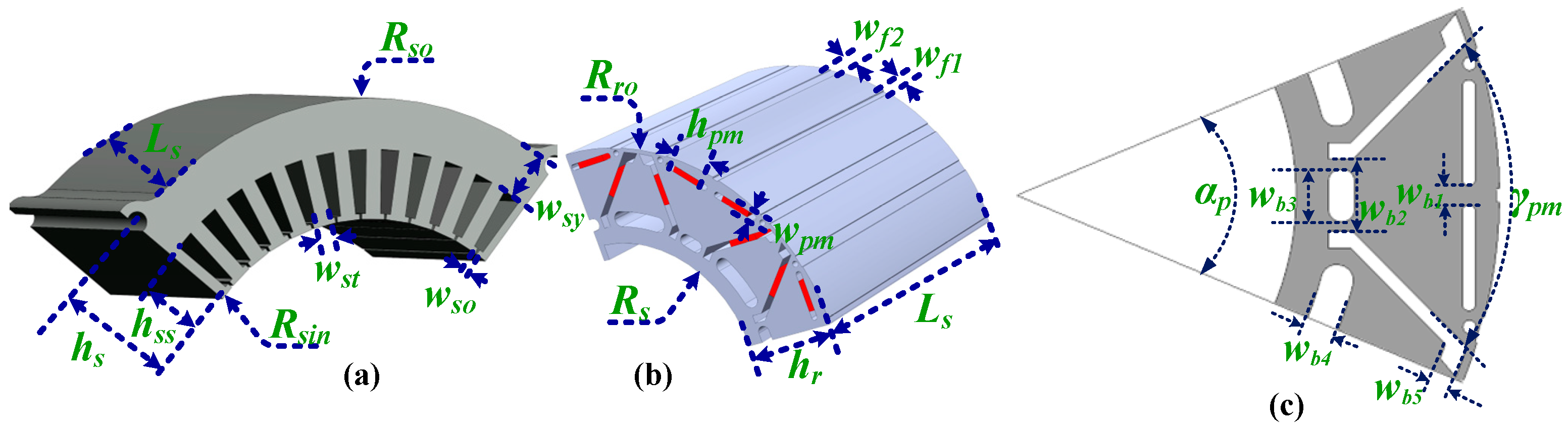
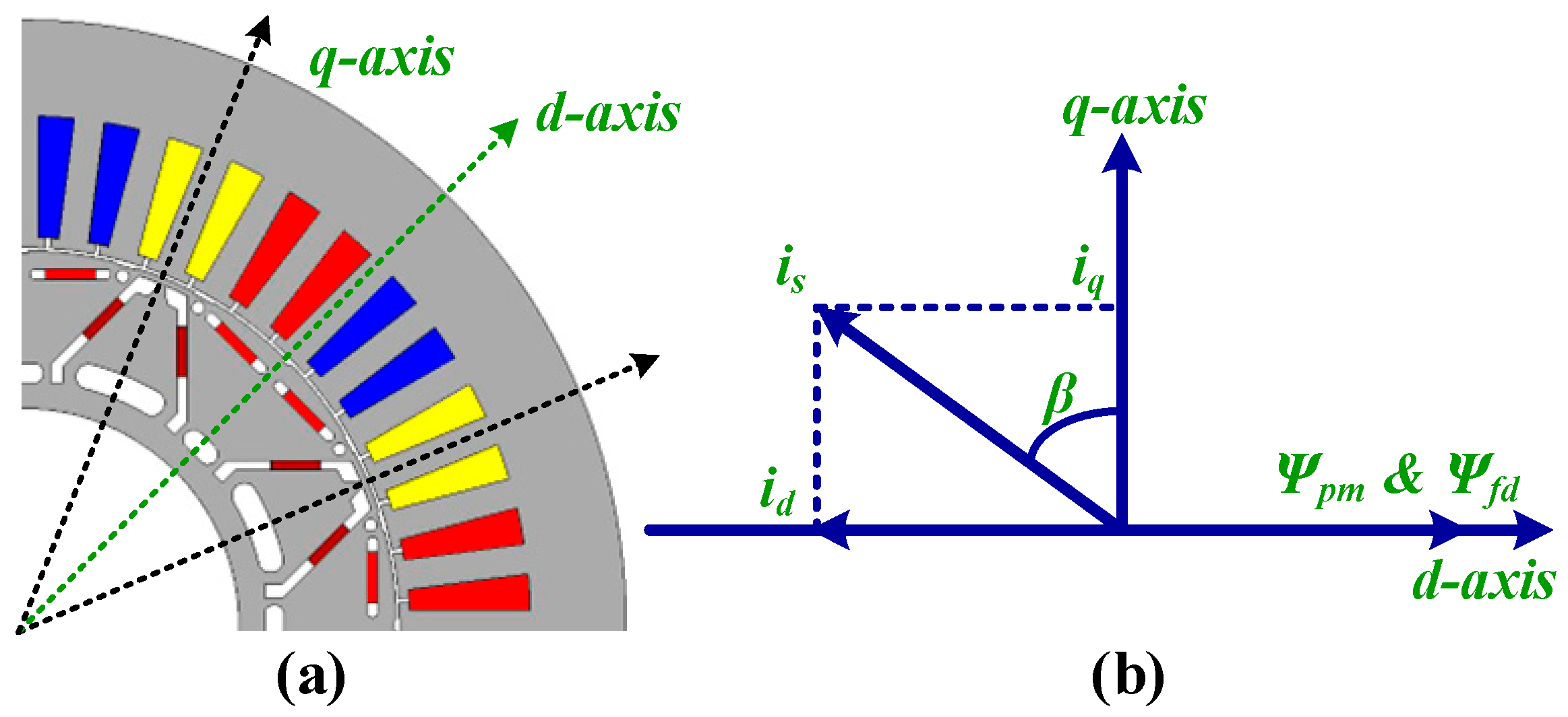
A cross-sectional view of the rotor and stator of the proposed SΔ-IPM is shown in Figure 2, with the design parameters illustrated in Figure 3 and listed in Table 1. The stator is composed of 48 slots with an integral-slot distributed winding, whereas the rotor has eight poles in the form of a segmented delta. It is clear that, in the PM arrangements, two types of PMs are used. The first is V-shaped PMs, whereas the second is bar-type PMs in the segmented form with a flux bridge between them. The reason for forming a segmented delta with the combination of two types of PMs is to improve both the reluctance torque and the PM torque performance. This torque performance is explained using the d- and q-axis coordinates and the vector diagram based on the PM flux and the stator current defined by rotor saliency, as shown in Figure 4.
The d- and q-axis flux linkages are written as [32]
Ψ d = Ψ f d + L d i d
Ψ q = Ψ f q + L q i q
where Ψ f d and Ψ f q are the synthetic PM fluxes at the d- and q-axis, respectively, and L d and L q are the parameters on the d-axis and the q-axis, respectively.
Accordingly, the PM flux linkages are modified as:
F o r   I P M   Ψ d = Ψ p m L d i s s i n β   Ψ q = L q i s c o s β  
F o r   A I P M   Ψ d = Ψ p m cos α L d i s s i n β   Ψ q = Ψ p m sin α + L q i s c o s β  
where i s is the stator current.
According to the principle of torque mechanism, the effective synthetic torque is composed of two main components: reluctance torque that is produced as a result of rotor saliency L d L q and PM torque which is generated as a result of PM flux linkage ( Ψ p m ) interaction with the armature current ( i q ). This general torque is written as:
T e = T p m + T r
where
T p m = 3 p 2 Ψ f d i d + Ψ f q i d
T r = 3 p 2 L d L q i d i q
where T p m and T r are the PM torque and reluctance torque, respectively. These torque components for IPM and AIPM machines are expressed as:
F o r   I P M   T p m = 3 p 2 Ψ p m i s cos β   T r = 3 p 4 L d L q i s 2 sin 2 β  
F o r   A I P M   T p m = 3 p 2 Ψ p m i s cos β α   T r = 3 p 4 L d L q i s 2 sin 2 β  
Thus,
F o r   I P M   T e = 3 p 2 Ψ p m i s cos β + 1 2 L d L q i s 2 sin 2 β   F o r   A I P M   T e = 3 p 2 Ψ p m i s cos β α + 1 2 L d L q i s 2 sin 2 β  
where β is the advanced current angle and α is the shift angle.
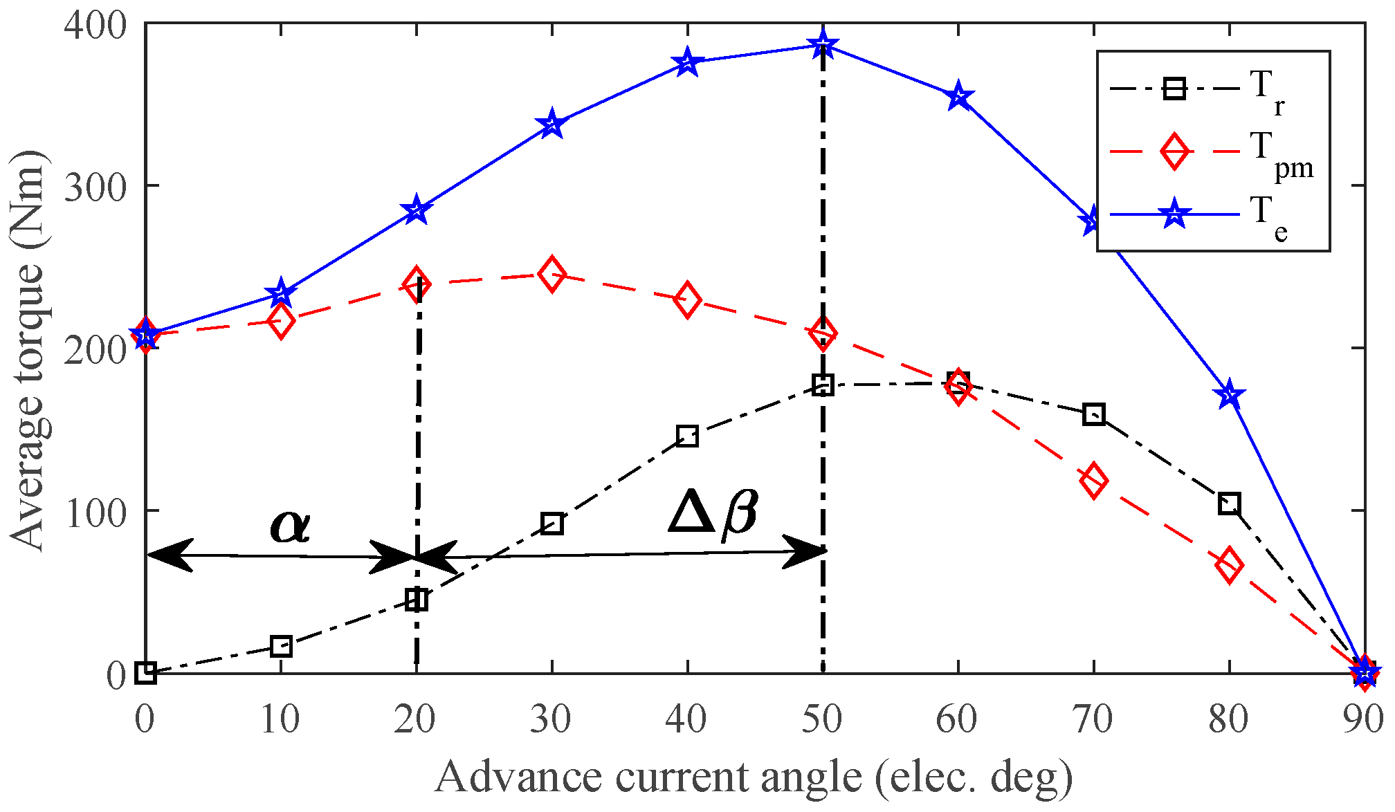
The torque profile and torque components with this advanced current are shown in Figure 5. It is evident that T p m reaches its maximum value at advance angle of 20 ° and T r reaches its maximum value at advance angles of 50 ° and 60 ° electrical degrees. However, for conventional IPMs, T p m reaches its maximum value at an advance angle of 0 ° and T r reaches its maximum value at an advance angle of 45 ° . Consequently, the angle difference for conventional IPMs becomes β = 45 ° , whereas for the proposed SΔ-IPM, this difference becomes β = 50 ° α . This shows that the maximum point of the PM and reluctance torque components is shifted close to each other with a shift angle of α = 20 ° . This analysis evidently shows that, despite the symmetrical design, due to the novel design approach of using the segmented delta with flux bridge and circular flux barriers, magnetic field shifting has been achieved in the PM torque component, thus improving the average synthetic torque.

3. Evaluation of Electromagnetic Performance

Finite element analysis (FEA)-based electromagnetic performance is investigated under no-load and on-load conditions.

3.1. No-Load Characteristics

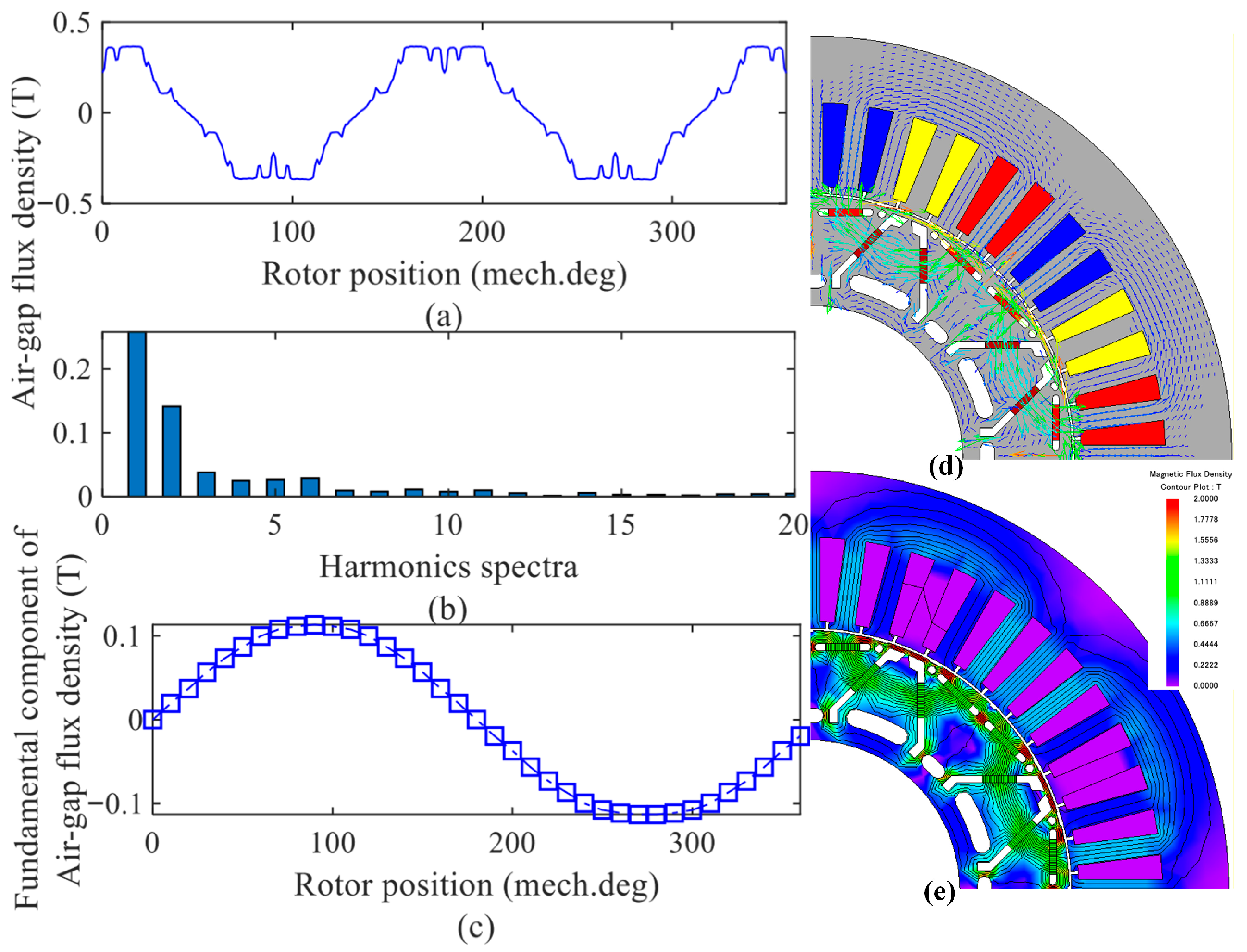
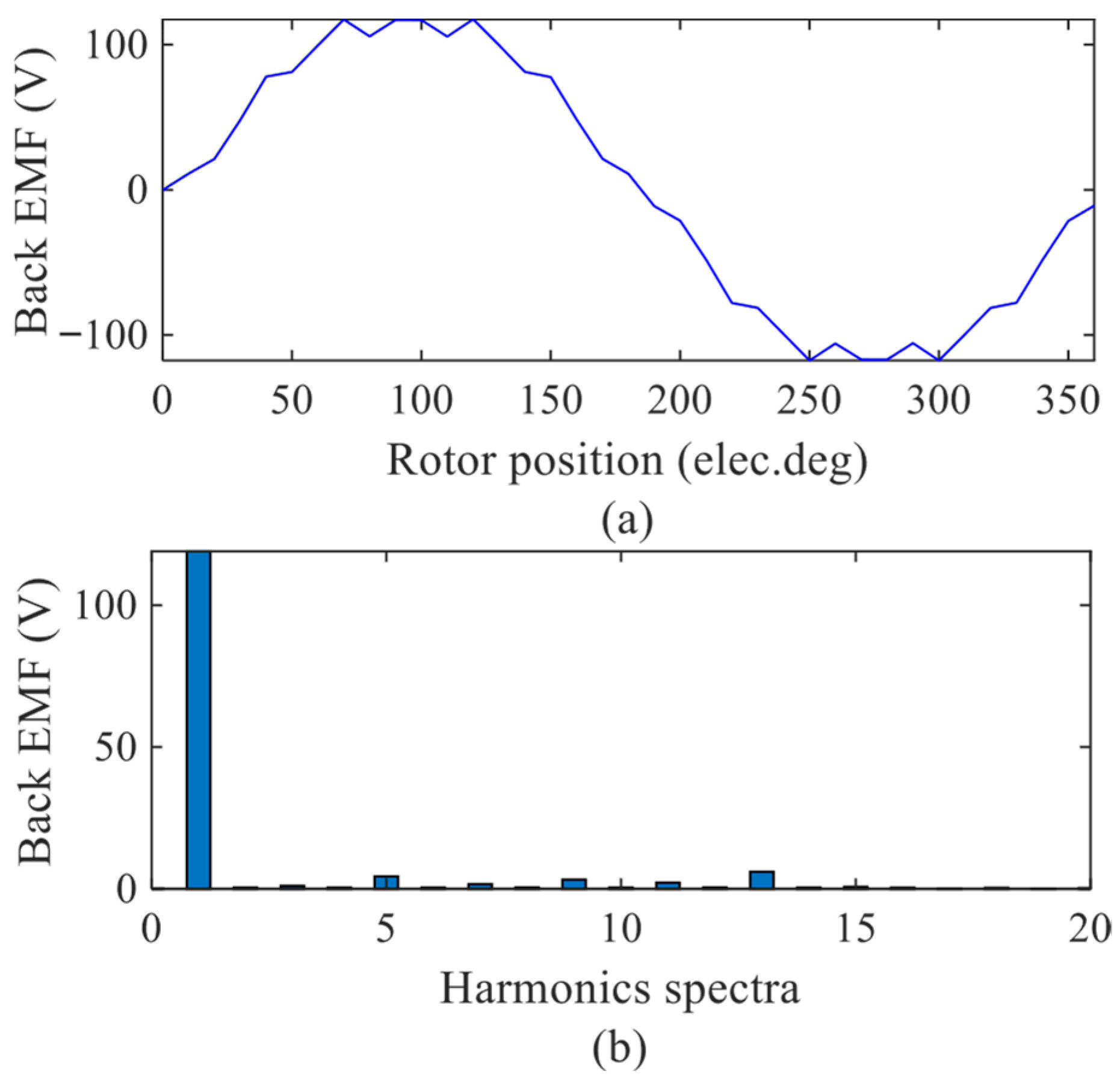
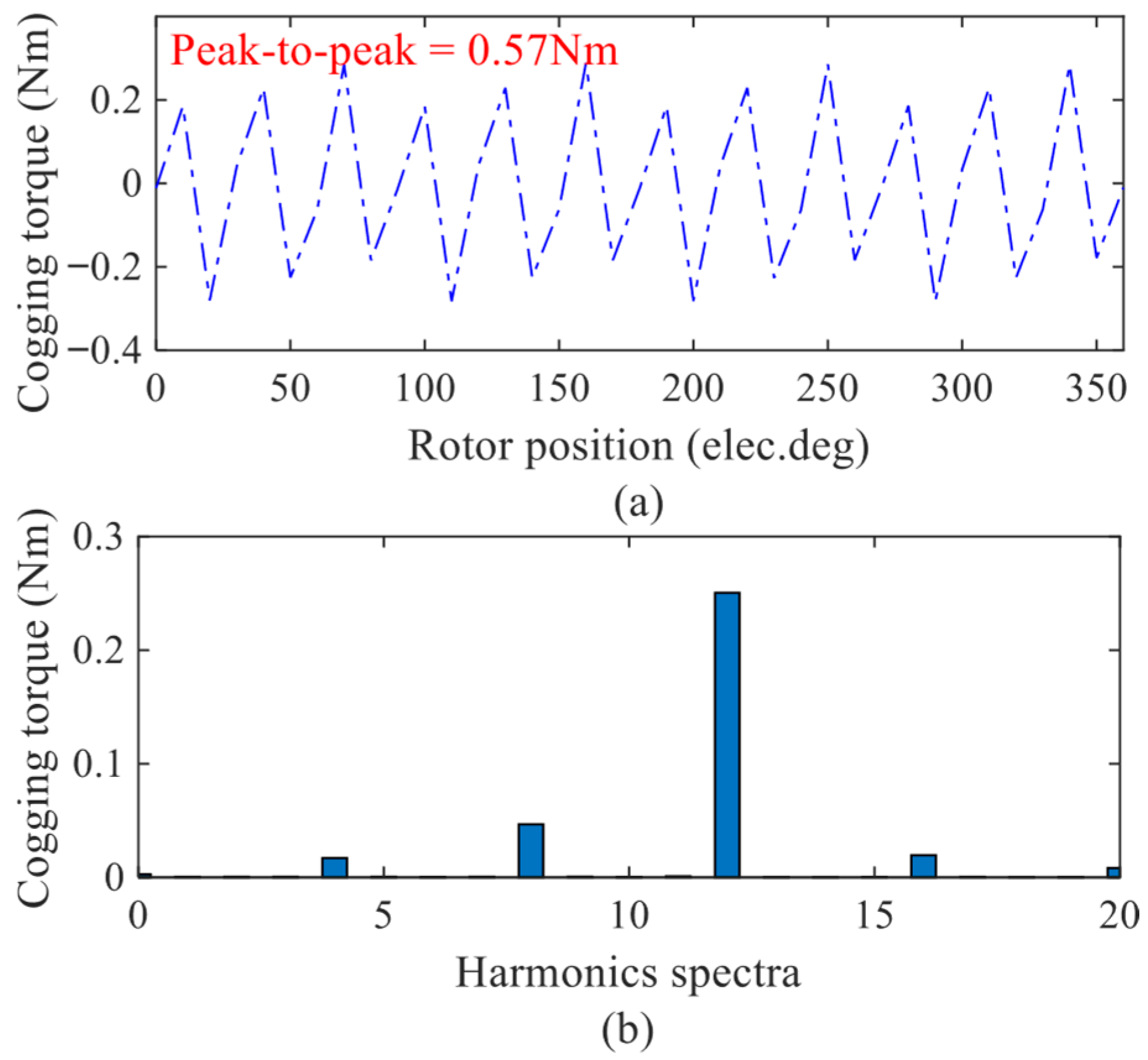
Under the no-load study, air-gap flux density, back-electromotive force (EMF) and cogging torque have been investigated as shown in Figure 6, Figure 7 and Figure 8.
Air-gap flux density describes how strong the magnetic field is in the air gap between the rotors and the stator. Due to operational and design considerations, air-gap flux density is not always a sine wave, resulting in harmonic components as clearly shown in Figure 6. The no-load air-gap flux density illustrated in Figure 6 shows a symmetrical waveform with notably minor distortion. The harmonic spectra confirm the existence of distortion in the form of higher-order harmonic components with small magnitudes. These extra frequencies are analysed via harmonic spectra, which highlight variations from the fundamental component waveform. Furthermore, the magnetic flux lines, linkages and flux distribution (as shown in Figure 6d,e) show that the design features of special flux barriers, flux bridges, and notches reshape and direct the flux linkages with minimum leakages and maximum linkages, which helps in improving torque components.
Under the no-load condition, when the rotor rotates, a voltage is induced that is opposed to the one being applied and is referred to as back-EMF. This self-induced voltage results from the magnetic interaction between the magnetic fields of the stationary stator and the revolving rotor. Back-EMF has a significant role in restricting current flow and regulating motor speed. This back-EMF waveform and the harmonic spectra for the proposed design are shown in Figure 7. The waveform consists of a basic frequency and harmonics, which are analysed in terms of harmonic spectra. The harmonics are integer multiples of the fundamental frequency, which is the same as the rotor’s rotational speed.
Under the no-load condition, the cogging torque waveform, peak-to-peak values, and the harmonic spectra have been investigated as shown in Figure 8. This cogging torque is generated when the rotor periodically encounters magnetic resistance because of the interaction between the permanent magnets and the magnetic field of the stator, resulting in fluctuations in instantaneous torque in the form of torque ripples. But the peak-to-peak values obtained are 0.57 Nm, which is acceptable. Moreover, the harmonic spectra show that the dominant cogging torque harmonic components are the 12th order harmonic, whereas the 4th, 8th and 16th components demonstrate minor contributions.

3.2. On-Load Characteristics

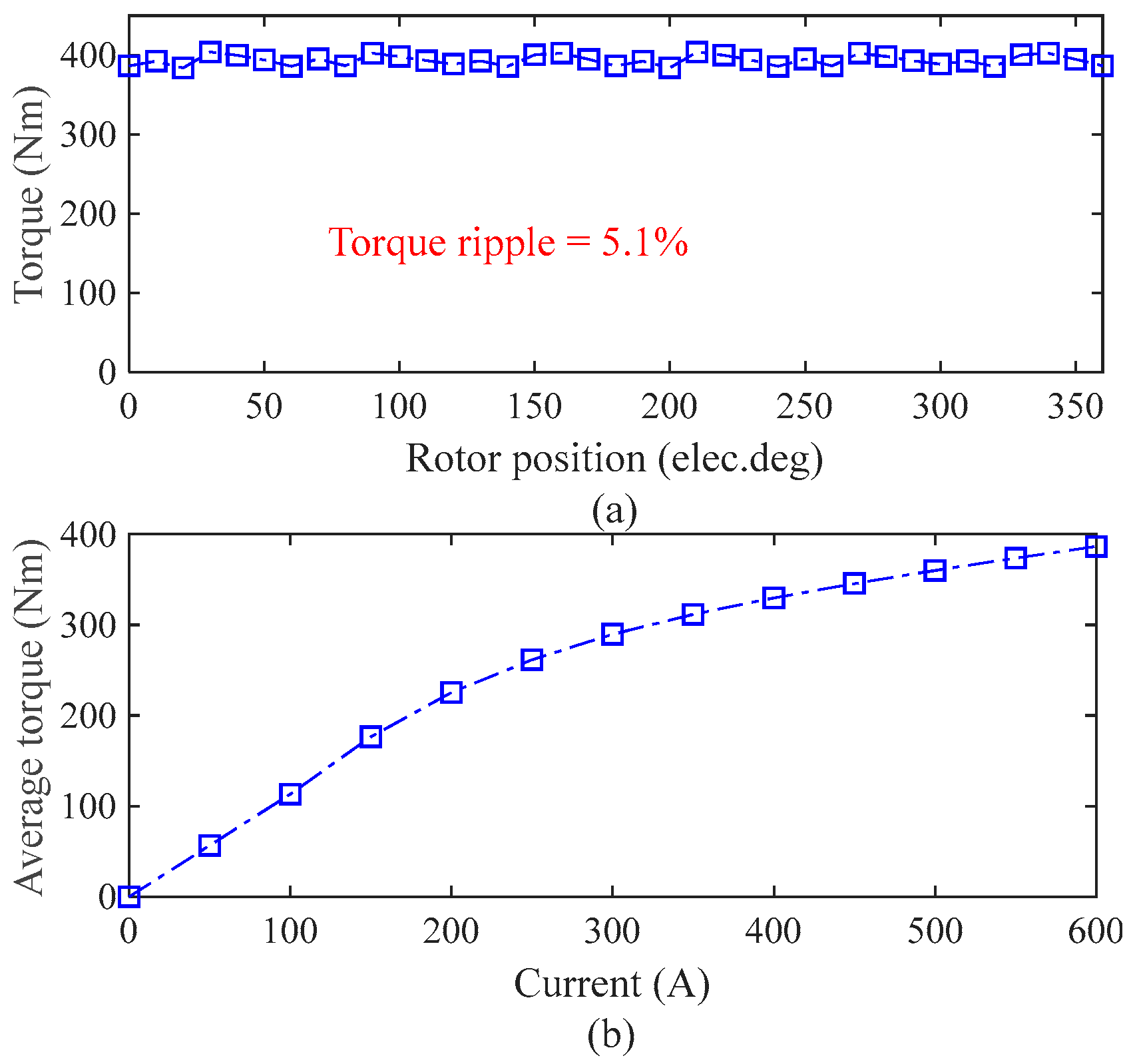
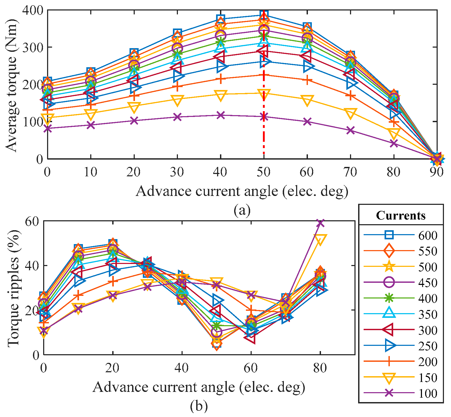
In on-load characteristics, the torque profile and torque ripples are investigated. In this regard, the instantaneous torque is shown in Figure 9a. It is evident that the average torque of 393.7 Nm is obtained with a torque ripple ratio of 5.1%. This low level of ripples confirms safe operation in terms of the pulsation in the torque profile. Additionally, the impact of armature reaction on the overload capability of the proposed design is investigated by examining average torque production as a function of applied current, as shown in Figure 9b. It is evident that the proposed SΔ-IPM design offers excellent overload capability even under higher applied current and torque production. Consequently, the average torque and torque ripple ratio under different applied currents and advance current angles have been evaluated as shown in Figure 10. It can be clearly seen that with increasing applied current, the average torque increases, whereas the torque ripple ratio first increases and then decreases at the optimum operating advance current angle. It is evident that at an advance angle of 50°, the torque ripple ratio reaches a minimum value of 5.1% and a maximum torque of 393.7 Nm at 600 A. Finally, some additional characteristics such as machine weight, output power, losses and efficiency are computed as listed in Table 2.

3.3. High-Speed Operation

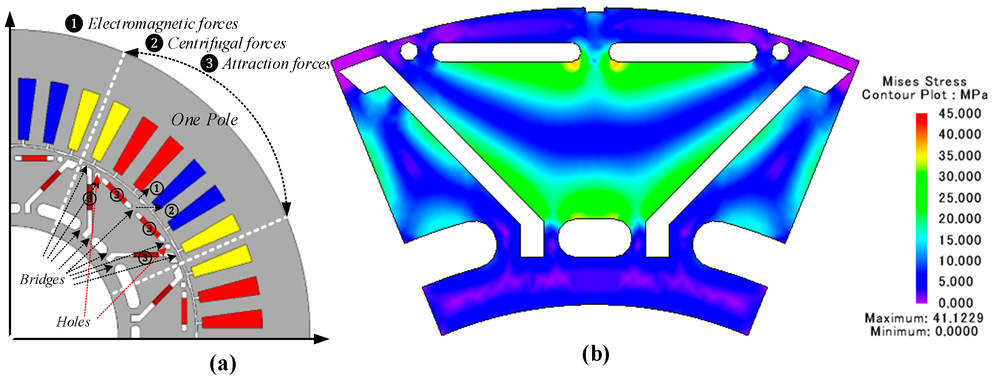
To elaborate on the mechanical robustness of the segmented delta design rotor under various operating conditions, such as high-speed operation, structural analysis is executed to examine mechanical stress on the various rotor sections of the proposed SΔ-IPM, especially the thin bridge, holes and segment areas, to investigate the von Mises stress due to electromagnetic force, centrifugal force and attractive force as shown in Figure 11a. It is important to note that the hole in the rotor inner section is already merged to reduce rotor mass and overcome centrifugal forces. The different forces act in different directions. Centrifugal forces act radially on the rotor; electromagnetic forces between the rotor and stator, predominantly in the radial direction; and attraction forces between the permanent magnet and the rotor. The attraction forces have opposite directions to the above two forces due to the permanent magnets, which are vertical to the boundary of the magnets.
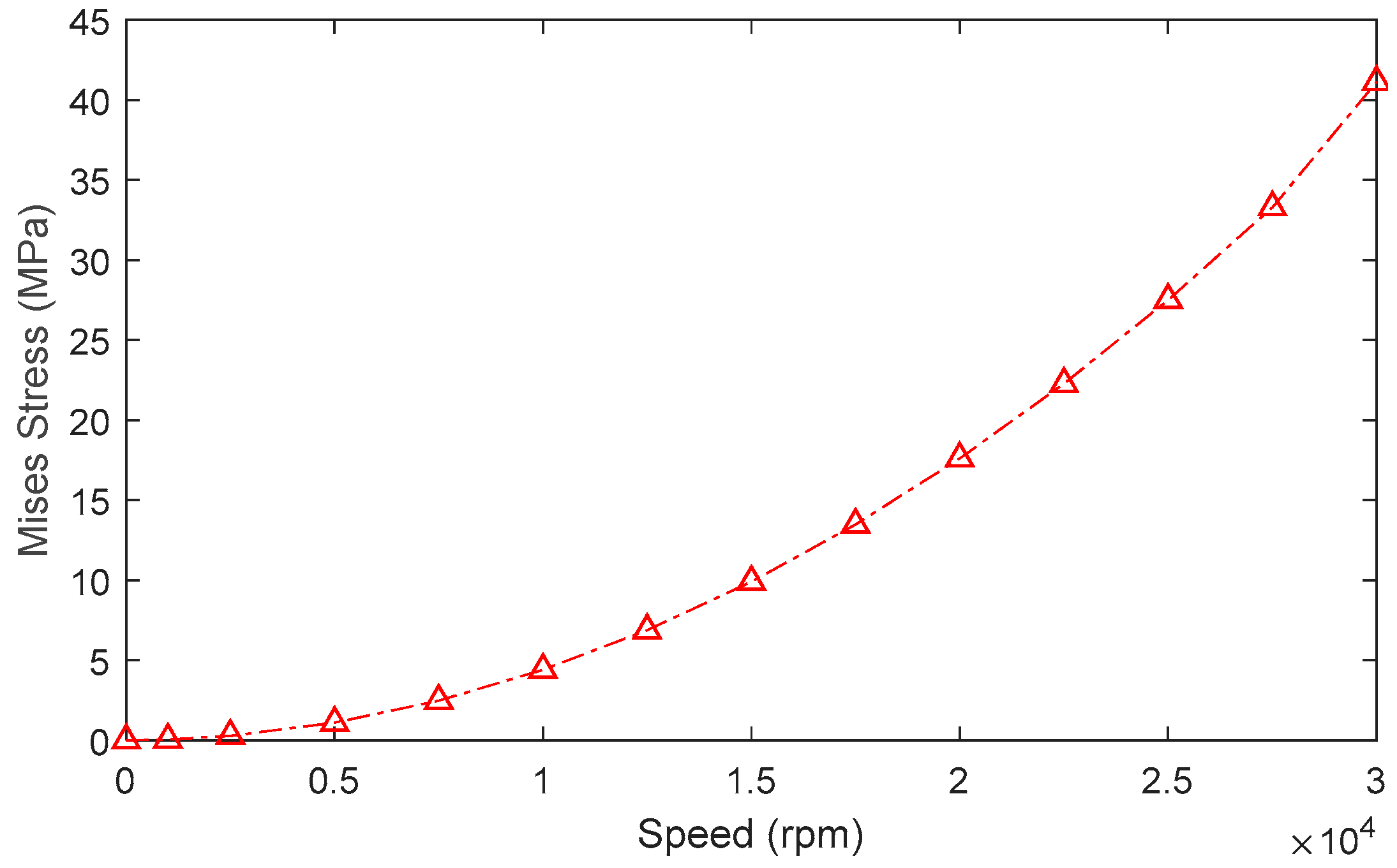
Mechanical stress analysis of the rotor is conducted by applying actual conditions and constraints in accordance with the material characteristics [33]. Since the rotor is subjected to centrifugal forces, the mechanical stress condition of the rotor structure is dominated by centrifugal force due to longitudinal rotor rotation. This centrifugal force is strongly influenced by the rotor’s angular velocity; therefore, analysis is carried out under various high-speed operating conditions to investigate the variation in principal stress across rotor sections. Since von Mises stress on the rotor varies with operating condition, i.e., rotating angular speed, the analysis is carried out from 0 to 30,000 rpm. Figure 11b shows a nephogram of the von Mises stress distribution on the rotor at 30,000 rpm, whereas its variation with operating speed is illustrated in Figure 12. Analysis reveals that with the change in rotating speed, the principal stress increases exponentially. Thus, it is concluded that rotor structures can withstand higher von Mises stress levels, ensuring their safe operation under high-speed operating conditions. Note that the smaller the principal stress, the better the machine safety is.

3.4. Thermal Analysis

IPM motors have been a research focus in the past decades due to growing interest in high efficiency and power/torque density. However, under high loading conditions, temperature rises due to heat generation by electromagnetic losses, i.e., core loss and eddy current losses, which affect machine performance. Therefore, thermal analysis is required at the design stage to ensure safe and reliable operation.
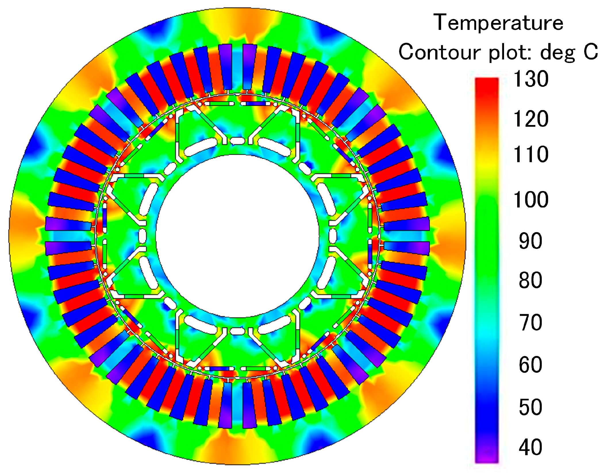
The proposed SΔ-IPM under rated condition has been investigated for temperature distribution using the coupled electromagnetic–thermal analysis [34,35,36]. Finite element analysis-based thermal analysis for temperature distribution under rated operating conditions is implemented as shown in Figure 13. The analysis shows that the maximum temperature of 120 °C is reached at the stator teeth, rotor flux bridge, and flux barriers. To ensure safe and reliable operation, class B and class F insulation is sufficient, and force cooling can further improve performance and maintain a lower temperature distribution.

4. Performance Comparison with State-of-the-Art Designs

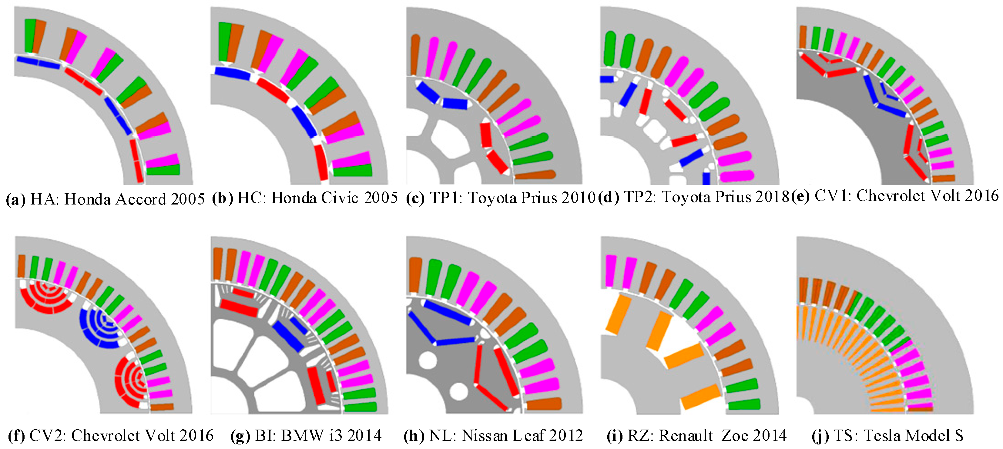
In order to show the effectiveness of the proposed SΔ-IPM design over existing state-of-the-art designs, a comparative analysis is conducted with Honda Accord 2005 (HA), Honda Civic 2005 (HC), Toyota Prius 2010 (TP1), Toyota Prius 2018 (TP2), Chevrolet Volt 2016 (CV1 and CV2), BMW i3 2014 (BI), Nissan Leaf 2012 (NL), Renault Zoe 2014 (RZ) and Tesla Model S (TS) as shown in Figure 14. The leading design parameters are listed in Table 3, and the performance summary is illustrated in Table 4. An extensive performance analysis is performed with key metrics such as PM weight, cogging torque, torque ripples, torque density, and power density. A detailed quantitative performance analysis of the proposed SΔ-IPM with the aforementioned state-of-the-art designs is discussed below.
  • Comparison of the proposed SΔ-IPM with HA shows a 27.84% reduction in PM weight and 2.33- and 2.71-fold increases in torque and power density, respectively. Furthermore, torque ripples are suppressed by 72.38%, and cogging torque is reduced by 94.80%.
  • Quantitative study of the proposed SΔ-IPM compared with HC shows a 27.84% reduction in PM weight and enhanced torque and power density by 1.81- and 1.88-fold, respectively. Additionally, cogging torque is reduced by 93.64% at the cost of a 45.29% increase in torque ripples.
  • Comparative study of the proposed SΔ-IPM with TP1 shows a 58.99% reduction in PM weight, whereas torque density is improved by 2.62% at the cost of a 20.64% reduction in power density. In addition, cogging torque is reduced by 43.45%, and torque ripples are suppressed by 47.9%.
  • Comparative analysis of the proposed SΔ-IPM with TP2 shows a 13.63% reduction in PM weight, 7.45% reduction in cogging torque and 83.65% suppression in torque ripples. Consequently, torque density improves by 2.62%, while power density reduces by 25.62%.
  • Analysis of the proposed SΔ-IPM with CV1 exhibits an 86.42% reduction in PM weight and an 82.93% reduction in cogging torque, along with a 92.45% increase in torque ripples. Moreover, torque density increases by 18.9%, while power density decreases by 3.3%.
  • Comparison with CV2 demonstrates a reduction of the PM weight by 36.6% and an enhancement of torque density by 84.19%, whereas power density reduces by 18%. In addition, cogging torque is reduced by 26.6%, and torque ripples are reduced by 82.27%.
  • Quantitative comparison of the proposed SΔ-IPM with BI shows a 71.5% reduction in PM weight and enhanced torque and power density by 83.91% and 23%, respectively. Furthermore, cogging torque is reduced by 78.07%, and torque ripples are reduced by 79.6%.
  • Comparative analysis of the proposed SΔ-IPM with NL shows a 66.47% reduction in PM weight and an 82.93% decrease in cogging torque, and torque ripples are reduced by 96.96% and 53.21%, respectively. Additionally, torque density improves by 28.54% at the expense of a 31.22% reduction in power density.
  • Finally, a comparison of the proposed SΔ-IPM with RZ and TS was conducted. Since RZ and TS adopt traditional wound-field design, comparisons of PM usage are excluded. It is important to note that RZ uses a DC rotor (wound-field, WF), while TS adopts an induction machine. Based on the available performance data, it is evident that the proposed SΔ-IPM offers 96.47% lower cogging torque and 81.13% lower torque ripple than RZ, and 43.27% lower torque ripple than the TS design. Moreover, torque and power density are 75.20% and 72.86% higher than the RZ model, respectively. Additionally, compared with the TS model, a 2.23 increase in torque density is achieved at the cost of a 22% reduction in power density.
Thus, based on the detailed summarised performance and comparative investigations, it is evident that the proposed SΔ-IPM offers better performance than most state-of-the-art alternatives, not only in terms of PM usage and torque density but also in terms of other electromagnetic performance metrics listed in Table 4. However, a potential trade-off is lower power density compared to some reported models.

5. Conclusions

In this paper, a novel SΔ-IPM with a three-notched rotor pole shape and circular flux barriers has been proposed. Torque performance is analytically discussed, and 2D FEA is used to evaluate the extensive electromagnetic performance. The analysis shows that due to the unique design featuring an intermediate flux bridge and circular flux barriers, an average torque of 393.7 Nm with torque ripples of 5.1% and a cogging torque of 0.57 Nm has been achieved. Additionally, an extensive comparative analysis with various state-of-the-art designs has been conducted, which confirms the effectiveness of the proposed design for high torque density. Thus, the analysis concludes that the proposed SΔ-IPM can be the best-suited design for high-performance EV applications.
The results demonstrate substantial minimisation of rare-earth PM usage, with reductions of up to 86.42% compared to existing designs, while still achieving significant improvements in torque density and acceptable overall performance across key metrics. These findings confirm that the proposed SΔ-IPM machine successfully realises the research goal by delivering a high-performance EV drive solution with markedly reduced reliance on rare-earth materials.

Author Contributions

Conceptualisation, W.U., M.A.A. and M.F.; methodology, W.U., M.F., U.B.A., H.S.S. and A.K.J.; software, W.U. and M.F.; validation, M.A.A., U.B.A., H.S.S., M.F.A. and A.K.J.; formal analysis, W.U. and M.F.; investigation, W.U., M.F. and M.A.A.; resources, W.U., M.A.A., U.B.A., H.S.S., M.F.A. and A.K.J.; data curation, W.U., M.F. and U.B.A.; writing—original draft preparation, W.U. and M.F.; writing—review and editing, W.U., M.F. and U.B.A.; visualisation, M.A.A. and U.B.A.; supervision, M.A.A. and U.B.A.; project administration, M.A.A., H.S.S., M.F.A. and A.K.J.; funding acquisition, H.S.S. and M.F.A. All authors have read and agreed to the published version of the manuscript.

Funding

This research received no external funding.

Data Availability Statement

Data will be available upon request from the corresponding author.

Acknowledgments

The authors acknowledge the technical support from the Artificial Intelligence and Sensing Technologies Research Center at the University of Tabuk.

Conflicts of Interest

The authors declare no conflicts of interest.

Abbreviations

The following abbreviations are used in this manuscript:
EVElectric Vehicles
IPMInterior Permanent Magnet
PMPermanent Magnet
FEAFinite Element Analysis
SΔ-IPMSegmented delta-shaped IPM
HEVsHybrid EVs
ICEInternal Combustion Engines
FSPMFlux Switching Permanent Magnet
FRPMFlux Reversal Permanent Magnet
SPMSurface-mounted Permanent Magnet
PMSMPermanent Magnet Synchronous Machines

References

  1. Liu, C.; Chau, K.T.; Kirtley, J.L.; Chan, C.C.; Rajashekara, K.; Cheng, M.; Jahns, T.M.; Zhang, Z.; Kwon, B.I.; Shek, J.; et al. Guest editorial emerging electric machines and drives for smart energy conversion. IEEE Trans. Energy Convers. 2018, 33, 1931–1933. [Google Scholar] [CrossRef]
  2. Laskaris, K.I.; Kladas, A.G. Internal permanent magnet motor design for electric vehicle drive. IEEE Trans. Ind. Electron. 2009, 57, 138–145. [Google Scholar] [CrossRef]
  3. Wang, A.; Jia, Y.; Soong, W.L. Comparison of five topologies for an interior permanent-magnet machine for a hybrid electric vehicle. IEEE Trans. Magn. 2011, 47, 3606–3609. [Google Scholar] [CrossRef]
  4. Dutta, R.; Rahman, M. Design and analysis of an interior permanent magnet (IPM) machine with very wide constant power operation range. IEEE Trans. Energy Convers. 2008, 23, 25–33. [Google Scholar] [CrossRef]
  5. Liang, J.; Feng, J.; Fang, Z.; Lu, Y.; Yin, G.; Mao, X.; Wu, J.; Wang, F. An Energy-Oriented Torque-Vector Control Framework for Distributed Drive Electric Vehicles. IEEE Trans. Transp. Electrif. 2023, 9, 4014–4031. [Google Scholar] [CrossRef]
  6. Kamiya, M. Development of traction drive motors for the Toyota hybrid system. IEEJ Trans. Ind. Appl. 2006, 126, 473–479. [Google Scholar] [CrossRef]
  7. Jahns, T.M.; Bianchi, N. Design Analysis and Control of Interior PM Synchronous Machines; IEEE Industry Application Society: Piscataway, NJ, USA, 2004; pp. 3.16–3.17. [Google Scholar]
  8. Cheng, M.; Hua, W.; Zhang, J.; Zhao, W. Overview of stator-permanent magnet brushless machines. IEEE Trans. Ind. Electron. 2011, 58, 5087–5101. [Google Scholar] [CrossRef]
  9. Yu, J.; Liu, C. Multi-objective optimization of a double-stator hybrid-excited flux-switching permanent-magnet machine. IEEE Trans. Energy Convers. 2019, 35, 312–323. [Google Scholar] [CrossRef]
  10. Gao, Y.; Li, D.; Qu, R.; Li, J. Design procedure of flux reversal permanent magnet machines. IEEE Trans. Ind. Appl. 2017, 53, 4232–4241. [Google Scholar] [CrossRef]
  11. Cao, R.; Mi, C.; Cheng, M. Quantitative comparison of flux-switching permanent-magnet motors with interior permanent magnet motor for EV, HEV, and PHEV applications. IEEE Trans. Magn. 2012, 48, 2374–2384. [Google Scholar] [CrossRef]
  12. Zhu, Z.Q.; Wu, D.; Ge, X. Investigation of voltage distortion in fractional slot interior permanent magnet machines having different slot and pole number combinations. IEEE Trans. Energy Convers. 2016, 31, 1192–1201. [Google Scholar] [CrossRef]
  13. Lei, G.; Liu, C.; Zhu, J.; Guo, Y. Techniques for multilevel design optimization of permanent magnet motors. IEEE Trans. Energy Convers. 2015, 30, 1574–1584. [Google Scholar] [CrossRef]
  14. Lu, X.; Iyer, K.L.V.; Mukherjee, K.; Ramkumar, K.; Kar, N.C. Investigation of permanent-magnet motor drives incorporating damper bars for electrified vehicles. IEEE Trans. Ind. Electron. 2014, 62, 3234–3244. [Google Scholar] [CrossRef]
  15. Liu, X.; Chen, H.; Zhao, J.; Belahcen, A. Research on the performances and parameters of interior PMSM used for electric vehicles. IEEE Trans. Ind. Electron. 2016, 63, 3533–3545. [Google Scholar] [CrossRef]
  16. Liang, J.; Wang, F.; Feng, J.; Zhao, M.; Fang, R.; Pi, D.; Yin, G. A Hierarchical Control of Independently Driven Electric Vehicles Considering Handling Stability and Energy Conservation. IEEE Trans. Intell. Veh. 2023, 9, 738–751. [Google Scholar] [CrossRef]
  17. Hu, Y.; Zhu, S.; Liu, C.; Wang, K. Electromagnetic performance analysis of interior PM machines for electric vehicle applications. IEEE Trans. Energy Convers. 2017, 33, 199–208. [Google Scholar] [CrossRef]
  18. Zhu, S.; Chen, W.; Xie, M.; Liu, C.; Wang, K. Electromagnetic performance comparison of multi-layered interior permanent magnet machines for EV traction applications. IEEE Trans. Magn. 2018, 54, 1–5. [Google Scholar] [CrossRef]
  19. Momen, F.; Rahman, K.; Son, Y. Electrical propulsion system design of Chevrolet Bolt battery electric vehicle. IEEE Trans. Ind. Appl. 2019, 55, 376–384. [Google Scholar] [CrossRef]
  20. Seo, J.M.; Ro, A.R.; Kim, R.E.; Seo, J. Hybrid analysis method considering the axial flux leakage in spoke-type permanent magnet machines. IEEE Trans. Magn. 2020, 56, 8200606. [Google Scholar] [CrossRef]
  21. Hsu, J.S.; Ayers, C.W.; Coomer, C.L. Report on Toyota/Prius Motor Design and Manufacturing Assessment; Oak Ridge National Laboratory U.S. Department of Energy’s: Oak Ridge, TN, USA, 2004.
  22. Burress, T.A.; Campbell, S.L.; Coomer, C.L. Evaluation of the 2010 Toyota Prius Hybrid Synergy Drive System; Oak Ridge National Laboratory U.S. Department of Energy’s: Oak Ridge, TN, USA, 2011.
  23. Dorrell, D.G.; Knight, A.M.; Evans, L.; Popescu, M. Analysis and design techniques applied to hybrid vehicle drive machines-assessment of alternative IPM and induction motor topologies. IEEE Trans. Ind. Electron. 2011, 59, 3690–3699. [Google Scholar] [CrossRef]
  24. Chen, Q.; Liu, G.; Zhao, W.; Sun, L.; Shao, M.; Liu, Z. Design and comparison of two fault-tolerant interior permanent-magnet motors. IEEE Trans. Ind. Electron. 2014, 61, 6615–6623. [Google Scholar] [CrossRef]
  25. Kimiabeigi, M.; Widmer, J.D.; Long, R.; Gao, Y.; Goss, J.; Martin, R.; Lisle, T.; Vizan, J.M.S.; Michaelides, A.; Mecrow, B. High-performance low-cost electric motor for electric vehicles using ferrite magnets. IEEE Trans. Ind. Electron. 2015, 63, 113–122. [Google Scholar] [CrossRef]
  26. Bianchi, N.; Mahmoud, H. An analytical approach to design the PM in PMAREL motors robust toward the demagnetization. IEEE Trans. Energy Convers. 2016, 31, 800–809. [Google Scholar] [CrossRef]
  27. Huynh, T.A.; Hsieh, M.-F. Comparative study of PM-assisted SynRM and IPMSM on constant power speed range for EV applications. IEEE Trans. Magn. 2017, 53, 1–6. [Google Scholar] [CrossRef]
  28. Cai, H.; Guan, B.; Xu, L. Low-cost ferrite PM-assisted synchronous reluctance machine for electric vehicles. IEEE Trans. Ind. Electron. 2014, 61, 5741–5748. [Google Scholar] [CrossRef]
  29. Lim, D.-K.; Ro, J.-S. Analysis and design of a delta-type interior permanent magnet synchronous generator by using an analytic method. IEEE Access 2019, 7, 85139–85145. [Google Scholar] [CrossRef]
  30. Chong, L.; Rahman, M. Saliency ratio derivation and optimisation for an interior permanent magnet machine with concentrated windings using finite-element analysis. IET Electr. Power Appl. 2010, 4, 249–258. [Google Scholar] [CrossRef]
  31. Lim, D.-K.; Yi, K.-P.; Woo, D.-K.; Yeo, H.-K.; Ro, J.-S.; Lee, C.-G.; Jung, H.-K. Analysis and design of a Multi-Layered and multi-segmented interior permanent magnet motor by using an analytic method. IEEE Trans. Magn. 2014, 50, 8201308. [Google Scholar] [CrossRef]
  32. Zhu, Z.-Q.; Xiao, Y. Novel Magnetic-Field-Shifting Techniques in Asymmetric Rotor Pole Interior PM Machines with Enhanced Torque Density. IEEE Trans. Magn. 2022, 58, 8100610. [Google Scholar] [CrossRef]
  33. Alani, M.; Oner, Y.; Tameemi, A. Electrical machines in automotive: Evaluation of current technologies and future requirements. Electr. Eng. 2023, 105, 477–491. [Google Scholar] [CrossRef]
  34. Ullah, W.; Khan, F.; Sulaiman, E.; Umair, M. Torque characteristics of high torque density partitioned PM consequent pole flux switching machines with flux barriers. CES Trans. Electr. Mach. Syst. 2020, 4, 130–141. [Google Scholar] [CrossRef]
  35. Ullah, W.; Khan, F.; Akuru, U.B.; Hussain, S.; Yousuf, M.; Akbar, S. A Novel Dual Electrical and Dual Mechanical Wound Field Flux Switching Generator for Co-Rotating and Counter-Rotating Wind Turbine Applications. IEEE Trans. Ind. Appl. 2023, 60, 184–195. [Google Scholar] [CrossRef]
  36. Ullah, W.; Khan, F.; Umair, M.; Sulaiman, E. Coupled electromagnetic-thermal analysis of segmented PM consequent pole flux switching machine. Chin. J. Electr. Eng. 2021, 7, 50–60. [Google Scholar] [CrossRef]
Figure 1. Electric machines classifications for EV/HEV applications.
Machines 14 00530 g001
Figure 2. Proposed SΔ-IPM: (a) cross-sectional view and (b) 3D view of rotor.
Machines 14 00530 g002
Figure 3. Parameters of SΔ-IPM: (a) stator, (b) rotor, and (c) segmented magnet.
Machines 14 00530 g003
Figure 4. Proposed SΔ-IPM: (a) d and q-axis coordinates, and (b) vector diagram.
Machines 14 00530 g004
Figure 5. Advance current angle–torque components characteristics.
Machines 14 00530 g005
Figure 6. Air-gap flux density: (a) waveform; (b) harmonic spectra; (c) fundamental component; (d) flux lines and flux linkage; and (e) magnetic flux distribution.
Machines 14 00530 g006
Figure 7. Back-EMF: (a) waveform and (b) harmonic spectra.
Machines 14 00530 g007
Figure 8. Cogging torque: (a) waveform and (b) harmonic spectra.
Machines 14 00530 g008
Figure 9. Torque: (a) Instantaneous waveform and (b) torque vs. current.
Machines 14 00530 g009
Figure 10. Effect of advance current angle on (a) average torque and (b) torque ripple ratio.
Machines 14 00530 g010
Figure 11. Distribution of (a) force on the rotor and (b) Mises stress @30,000 rpm.
Machines 14 00530 g011
Figure 12. Variation in the von Mises stress with operating speed.
Machines 14 00530 g012
Figure 13. Temperature distribution at the rated operating condition.
Machines 14 00530 g013
Figure 14. State-of-the-art industry models: (a) HA, (b) HC, (c) TP1, (d) TP2, (e) CV1, (f) CV2, (g) BI, (h) NL, (i) RZ, and (j) TS [33].
Machines 14 00530 g014
Table 1. Design parameters of the proposed SΔ-IPM.
SymbolValue (mm)SymbolValue (mm)
R s i n 75 w s y 19
R s o 120 h s 45
R o r 74.3 h r 31.3
R s 43 w f 1 2
L s 120 w f 2 4
h s s 24 w p m 2
w s o 0.81 h p m 10
w s t 6 α p 45°
γ p m 36.72° w b 1 3
w b 2 11 w b 3 8
w b 4 5 w b 5 3.68
Table 2. FEA-based predicted performance of the proposed SΔ-IPM.
Performance ValueUnit
2D FEA3D FEA
Average torque 393.7391.4Nm
Torque ripple ratio5.15.4%
Output power 103.073102.416kW
Machine weight 32.2332.23Kg
Copper losses1.07891.365kW
PM eddy current losses1.7951.859W
Core losses3.7193.787kW
Efficiency 93.9893.59%
Table 3. Design specifications of the proposed SΔ-IPM and state-of-the-art designs [33].
SpecificationHAHCTP1TP2CV1CV2BINLRZTSProposed
TopologySPMSPMIPMIPMIPMPMSMPMSMIPMFWIMIPM
Winding typeC-DLC-DLD-SLD-SLD-SLD-SLD-SLD-SLD-SLD-DLD-SL
Coil per phase888812121288129
Peak phase current225250235700325325400480480900600
Stator slots2424484872727248486048
Rotor pole pairs8888121264848
Stator outer diameter (mm)335265264214340340242198.12250254240
Axial length (mm)404050.86051.531.5132151.16155152120
PM weight (kg)0.790.791.390.664.20.921.7--0.57
Total motor weight (kg)22.8618.2219.0815.930.1519.64233.148.660.332.23
C-DL: Concentrated double layer, D-SL: Distributed single layer, PMSM: Permanent magnet synchronous machine, IM: Induction machine.
Table 4. Performance comparison of the proposed SΔ-IPM with state-of-the-art designs [33].
PerformanceHAHCTP1TP2CV1CV2BINLRZTSProposed
Cogging torque (pk-pk) (Nm)10.978.971.310.533.340.452.618.816.19-0.57
Torque ripples at peak current 18.473.519.7931.22.6528.782510.927.038.995.1
Average torque at peak current 119.5122.8227.9191309.8130.1300314.7339330393.709
Torque density (Nm/kg)5.226.7311.91210.276.636.649.56.975.4712.212
Torque per PM weight (Nm/kg)151.2155.4163.928973.76118.293.75185--683.64
Maximum output power (kW)27.2317768.4100.478.212115490.2250103.073
Power density (kW/kg)1.181.74.034.33.33.92.64.651.854.13.198
PM weight (kW/kg)34.439.255.39103.623.986.837.890.5--178.977
Disclaimer/Publisher’s Note: The statements, opinions and data contained in all publications are solely those of the individual author(s) and contributor(s) and not of MDPI and/or the editor(s). MDPI and/or the editor(s) disclaim responsibility for any injury to people or property resulting from any ideas, methods, instructions or products referred to in the content.