Article

Research on Fault-Tolerant Synchronous Control of Dual Motors for Wire-Controlled Steering Based on Average Deviation Coupled Fuzzy PID

1
School of Automotive and Transportation Engineering, Jiangsu University, Zhenjiang 212013, China
2
Nexteer Automotive Systems (Suzhou) Co., Ltd., No. 72 Fengli Street, Suzhou Industrial Park, Suzhou 215021, China
*
Author to whom correspondence should be addressed.
Machines 2026, 14(5), 495; https://doi.org/10.3390/machines14050495
Submission received: 15 March 2026 / Revised: 15 April 2026 / Accepted: 16 April 2026 / Published: 28 April 2026
(This article belongs to the Section Electrical Machines and Drives)

Abstract

To satisfy the stringent functional-safety requirements of steer-by-wire steering systems for advanced autonomous driving, this paper proposes a novel dual-motor collaborative fault-tolerant control strategy. The proposed approach aims to overcome the insufficient fault tolerance of conventional single-motor architectures, as well as the limited dynamic response and disturbance-rejection capability observed in existing multi-motor schemes. The key contribution is an integrated control framework consisting of two components: (i) dual-motor torque synchronization achieved via a fuzzy-PID–based mean-deviation coupling method, and (ii) a super-spiral sliding-mode control law optimized by an adaptive differential-evolution algorithm to enhance the dynamic performance and robustness of the current loop. Experimental results demonstrate that, relative to a non-synchronized baseline, the proposed strategy reduces the inter-motor current mismatch by 8.1–78.6% across multiple operating conditions. Moreover, following fault occurrence, the proposed Self-Adaptive Differential-Evolution-algorithm-based Super-Twisting Sliding-Mode Control method shortens the stabilization time by 50–70%, 9–20%, and 16.7% compared with conventional PID, Super-Twisting Sliding-Mode Control methods, and classical H robust control, respectively. Overall, the developed solution meets functional-safety requirements and provides a highly reliable steering-actuation mechanism for advanced autonomous driving applications.

1. Introduction

With the rapid advancement of autonomous driving and vehicle electrification, electronically controlled steering systems—such as Electric Power Steering (EPS) and Steer-by-Wire (SBW)—have attracted increasing attention and have begun to be deployed in practice. However, the growing complexity of steering systems inevitably increases the probability of functional malfunctions, particularly those originating from electronic components and control units [1]. Accordingly, functional safety has become a critical requirement for steering-by-wire applications. SBW is widely regarded as a promising steering solution for modern vehicles; nonetheless, functional-safety engineering remains fundamental to ensuring safe vehicle operation. By adopting key measures—including redundant architectures, fault detection and diagnostic procedures, and fault-tolerant control mechanisms-the risk of system—level failure can be substantially reduced, thereby enhancing protection for both drivers and passengers.
In the absence of an effective fault-tolerance mechanism, an SBW system may fail to maintain stable operation when the steering motor malfunctions, which makes it difficult to satisfy the reliability demands of future autonomous vehicles [2]. To address this issue, Xu et al. [3] proposed an event-triggered adaptive fuzzy switching fault-tolerant control strategy for dual-motor steer-by-wire systems, which considers load fluctuation and limited communication bandwidth. Shi et al. [4] investigated the angle tracking and fault-tolerant control of steer-by-wire systems with dual three-phase permanent magnet synchronous motors for autonomous vehicles, while He et al. [5] designed a dual-motor redundancy strategy for SBW. Poudel et al. [6] proposed a dual-control synchronous backup scheme; however, motor stability under fault conditions was not fully considered. More broadly, existing studies primarily emphasize redundant architecture design to guarantee continuity of operation, but they often fail to explicitly address stability during the transient phase immediately after motor faults. To meet functional-safety requirements, this paper proposes a fault-tolerant control strategy based on dual-motor torque synchronization, aiming to achieve high-precision synchronization under normal conditions and to ensure smooth and stable transition to single-motor operation in the event of a fault.
Meanwhile, accurate fault diagnosis serves as a critical prerequisite for efficient fault-tolerant control. For instance, Miguel et al. [7] proposed an active steering fault diagnosis scheme via integrated LSTM-based sensor detection and robust actuator fault estimation, which can accurately identify actuator faults and provide reliable information for subsequent fault-tolerance operations. Yang et al. [8] designed an adaptive unknown input observer for steer-by-wire systems to achieve simultaneous estimation of actuator and sensor faults, and further developed a corresponding sliding-mode fault-tolerant control scheme to improve steering accuracy under faulty conditions. For redundant steering systems driven by dual-winding motors, Zhu et al. [9] presented a hybrid data-driven and mechanism-based fault diagnosis strategy for current sensors, which realizes fast fault detection, localization and classification, and guarantees reliable fault-tolerant operation through signal compensation or mode switching. Nevertheless, due to space limitations, in-depth research on fault diagnosis algorithms is not further conducted in this paper.
When motor faults occur, current oscillations, torque ripples, and abnormal output behavior may arise. These phenomena place stringent requirements on current-loop control, particularly in terms of dynamic response, disturbance rejection, and robustness. Guo et al. [10] developed an improved PI controller for both current and speed loops. Teng et al. [11] designed a lumped-disturbance observer in the current loops of interior permanent magnet synchronous motors based on a recursive integral sliding-mode surface, which unifies various non-ideal factors as the lumped disturbances of stator voltage and avoids the problems of noise sensitivity and singularity existing in traditional terminal-sliding-mode observers. Shang et al. [12] introduced a multi-sliding-mode model-reference adaptive framework based on proportional–integral control. Chen et al. [13] presented a proportional–resonant current-loop active disturbance-rejection control method, and Gao [14] proposed a model-predictive current-control strategy incorporating variable-structure active disturbance rejection. Although these studies have advanced current-loop control theory, challenges remain in complex real-world conditions, especially under fault scenarios. Therefore, this work focuses on addressing these practical issues beyond idealized assumptions.
Existing approaches to improve motor disturbance rejection, robustness, and stability include PID control [15,16], Active Disturbance-Rejection Control (ADRC) [17,18], Sliding-Mode Control (SMC) [19], and related methods. Conventional PID often exhibits limited dynamic performance and robustness. Although ADRC provides favorable tracking and robustness, its performance can be sensitive to strong external disturbances and modeling uncertainties. By contrast, SMC is well known for its resilience to disturbances and parameter variations [20]. Nevertheless, conventional SMC may introduce pronounced chattering, which is undesirable for the control objectives of this study. To ensure stable motor control during fault isolation and post-fault transients, this paper adopts Super-Twisting Sliding-Mode Control (STSMC), which mitigates chattering through high-order sliding-mode characteristics [21], and further integrates Self-Adaptive Differential Evolution (SADE) to optimize and adjust control parameters.
Given the elevated functional-safety requirements of SBW systems, establishing a coordinated control strategy with strong robustness and reliable synchronization is essential. Dual-Motor Systems (DMS) typically exhibit strong coupling, nonlinearity, and time-varying characteristics [22]. Under external disturbances and parameter variations, tracking performance and robustness can degrade significantly [23,24]. In addition, the presence of two drive motors may lead to asynchronous responses, which can reduce steering effectiveness, shorten service life, increase energy loss, and in severe cases contribute to safety-critical events [25]. Consequently, investigating robust and synchronized cooperative control strategies for DMS is of substantial practical importance.
Recent studies have explored synchronization control for DMS. Zou et al. [26] proposed a dual-motor tracking and synchronization approach by combining STSMC with an average-deviation-angle strategy. Hwang et al. [27] presented an SMC-based synchronization framework using a perturbation observer within a master–slave architecture. Hua et al. [28] addressed out-of-synchronization phenomena using differential negative feedback to achieve synchronization. However, these studies generally do not consider the specific configuration in which two motors jointly drive the same rack to move bidirectionally through a reduction mechanism. Moreover, many existing approaches assume that the two motors can be controlled independently. In the dual-motor steer-by-wire system studied here, forced synchronization is partially imposed by the mechanical structure with extremely small angular differences; therefore, some control problems emphasized in the above studies have limited practical relevance for this particular engineering scenario.
Chen et al. [29] investigated a dual-motor rigid-shaft configuration and employed cross-coupling control in the current loop. However, the control structure is relatively simple and parameter tuning can be challenging. Motivated by these limitations, this study achieves torque synchronization via current regulation and employs a fuzzy-PID controller to compensate the inter-motor current difference, thereby improving synchronization performance.
This study proposes a dual-motor cooperative control scheme to achieve high-performance operation and functional safety through a multi-layer control architecture. In the core control layer, a current-loop STSMC strategy optimized by SADE is developed. By tuning control parameters online, SADE alleviates the typical drawbacks of conventional SMC-based designs, such as difficult parameter calibration and performance degradation caused by fixed parameters, thereby improving steady-state accuracy and dynamic resilience under fault conditions. In the cooperative control layer, a fuzz-PID-based mean-deviation coupling-compensation mechanism is established to enhance torque synchronization. Specifically, the mechanism monitors inter-motor current disparity in real time and adaptively adjusts the compensation term, ensuring consistent torque output from both motors.

2. System Dynamics Model

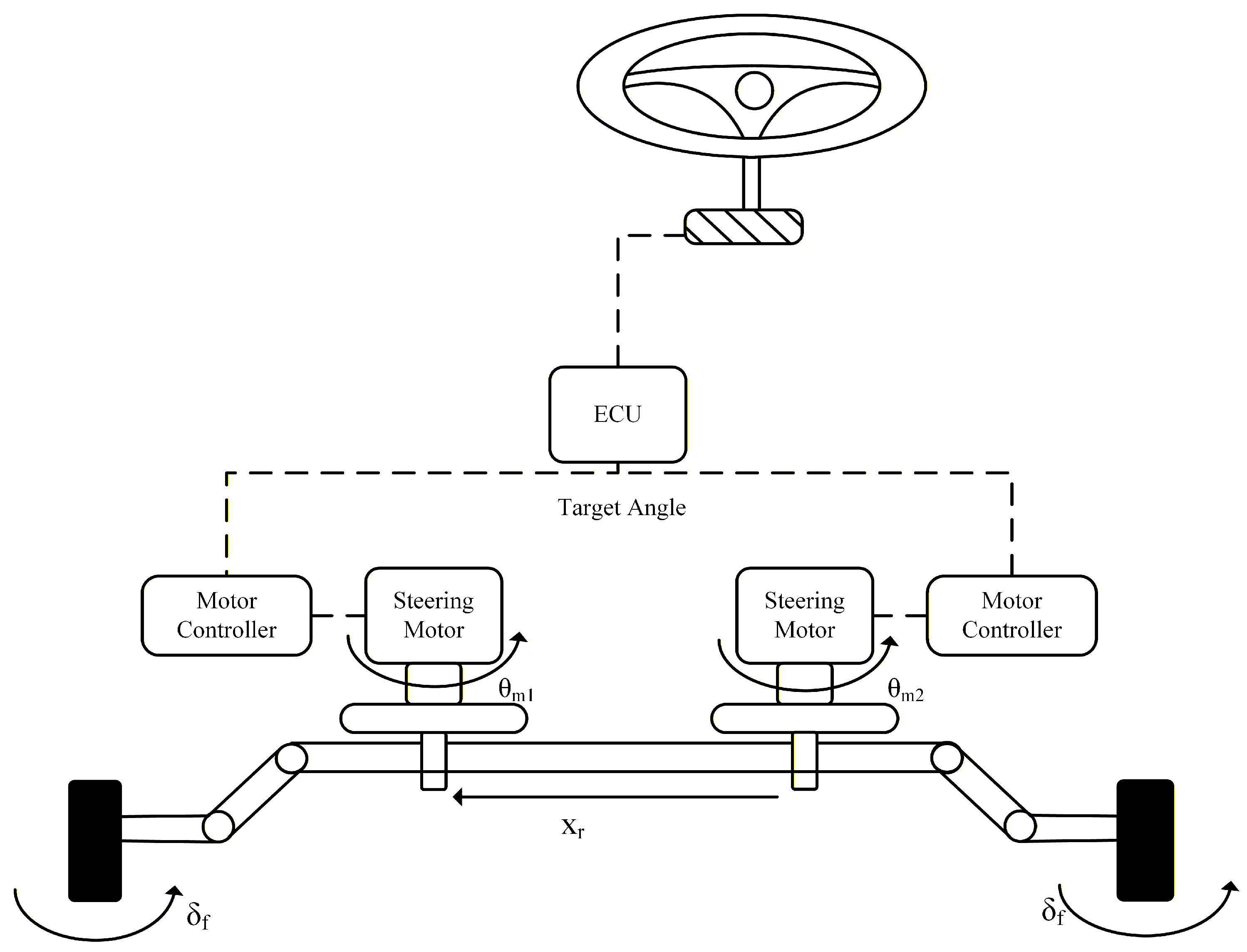
The SBW system adopts a Dual-Motor Driving System (DMDS), which mainly comprises two parallel steering drive motors, reduction gear assemblies, and a rack-and-pinion steering mechanism. In this configuration, both drive motors are Permanent-Magnet Synchronous Motors (PMSM) with identical rated parameters, as illustrated in Figure 1. The torque generated by each steering motor is amplified through the reduction transmission and then delivered to the output pinion. The pinion meshes with the rack gear, driving the rack to translate laterally. The rack displacement is subsequently transmitted through the steering linkage—namely, the left and right tie rods and the steering knuckle arms—so that the front wheels can overcome the steering resisting moment and achieve the desired steering-angle adjustment. This dual-motor configuration enhances redundancy and overall reliability, and it further enables flexible and accurate steering actuation by coordinating the torque outputs of the two motors. Moreover, employing PMSMs as the actuation source supports high efficiency and favorable dynamic response from the system.

2.1. Mathematical Model of Permanent Magnet Synchronous Motor

The PMSM is characterized by its simplicity, high efficiency, and excellent control properties. Two types of PMSM are selected for investigation in this study. To study and model simplicity and reliability, they are simplified. In the natural coordinate system, according to Kirchhoff’s voltage law and Faraday’s electromagnetic induction law, the motor voltage and flux equation can be obtained as follows:
u a u b u c = R a 0 0 0 R b 0 0 0 R c i a i b i c + p φ a φ b φ c
φ a φ b φ c = L a M a b M a c M b a L b M b c M c a M b c L c i a i b i c + p φ f a φ f b φ f c
where u a , u b and u c signify the motor’s three-phase voltage; the three-phase winding resistors of the motor are indicated by R a , R b and R c ; i a , i b and i c refer to the motor’s three-phase current; the three-phase winding magnetic linkage of the motor is given by φ a , φ b and φ c of the motor; p indicates the motor’s pole count; the three-phase winding self-inductance of the motor is designated as L a , L b and L c ; M a b , M a c , M b a , M b c , M c a and M b c signify the motor’s three-phase windings mutual inductance; and φ f a , φ f b and φ f c refer to the motor’s permanent magnet-generated three-phase winding flux.
This study chooses the mathematical model in the synchronous rotating coordinate system, and gives the motor’s stator voltage and the magnetic flux equation as follows:
u d = R i d + d d t φ d ω e φ q u q = R i q + d d t φ q + ω e φ d
φ d = L d i d + ψ f φ q = L q i q
where u d and u q signify the stator voltage d q axis components; the stator current d q axis components are indicated by i d and i q ; φ d and φ q refer to the stator flux d q axis components; the d q axis inductance components are designated as L d and L q ; ω e indicates the electromechanical angular velocity; and the motor’s permanent magnet flux linkage is given by ψ f .

2.2. Steering Execution Unit

The steering motor and speed reducer, the steering gear, and the tie rod comprise the steering execution unit. The steering gear used is the rack and pinion type. This paper adopts the dual-motor structure, so the dual-motor dynamics and reducer dynamics equations are established as follows:
T m 1 = K t 1 i m 1 T m 2 = K t 2 i m 2
T m 1 = J m 1 θ ¨ m 1 + B m 1 θ ˙ m 1 + T L 1 T m 2 = J m 2 θ ¨ m 2 + B m 2 θ ˙ m 2 + T L 2
T L i = K m i θ m i G X r / r p
where T m 1 and T m 2 are the electromagnetic torque of the two executive steering motors, respectively; K t 1 and K t 2 represent the electromagnetic torque coefficients of the two executive motors, respectively; i m 1 and i m 2 denote the current of the two motors, respectively; J m 1 and J m 2 are the moment of inertia of the rotor of the two motors, respectively; θ m 1 and θ m 2 represent the angles of the two motors, respectively; B m 1 and B m 2 are the damping coefficients of the rotor of the two motors; T L 1 and T L 2 denote the load torques of the two motors, respectively; K m i is the stiffness coefficient of the motor rotor; G represents the reduction ratio of the two motor retarders; X r denotes the rack displacement; and r p denotes the radius of the steering gear.
Here is the rack and pinion’s dynamic equation:
M r X ¨ r + B r X ˙ r + F r + 2 T k p r L = G r p ( T L 1 + T L 2 )
where M r denotes the mass of the rack; B represents the damping coefficient of the rack; F denotes the steering resistance of the rack; T k p denotes the torque exerted by the steering wheel on the kingpin; and r L denotes the mains pin offset.
The steered wheel’s mathematical model is as follows:
J f w δ ¨ f + B f w δ ˙ f = T k p T f w M z
where J f w denotes the moment of inertia of the steering front wheel around the kingpin; δ f denotes the angle of the front wheel; B f w denotes the viscous damping coefficient; T f w denotes the equivalent friction torque of the steering wheel kingpin; and M z denotes the steering resistance moment acting on the kingpin, and is mainly related to the wheel aligning torque.

2.3. Fault Injection

As functional safety becomes increasingly critical for SBW systems, fault-tolerant control has become an essential technique for ensuring system reliability. In this study, a representative inverter fault is selected as the injected-fault scenario to evaluate the proposed controller in terms of stability and fault-tolerance capability.
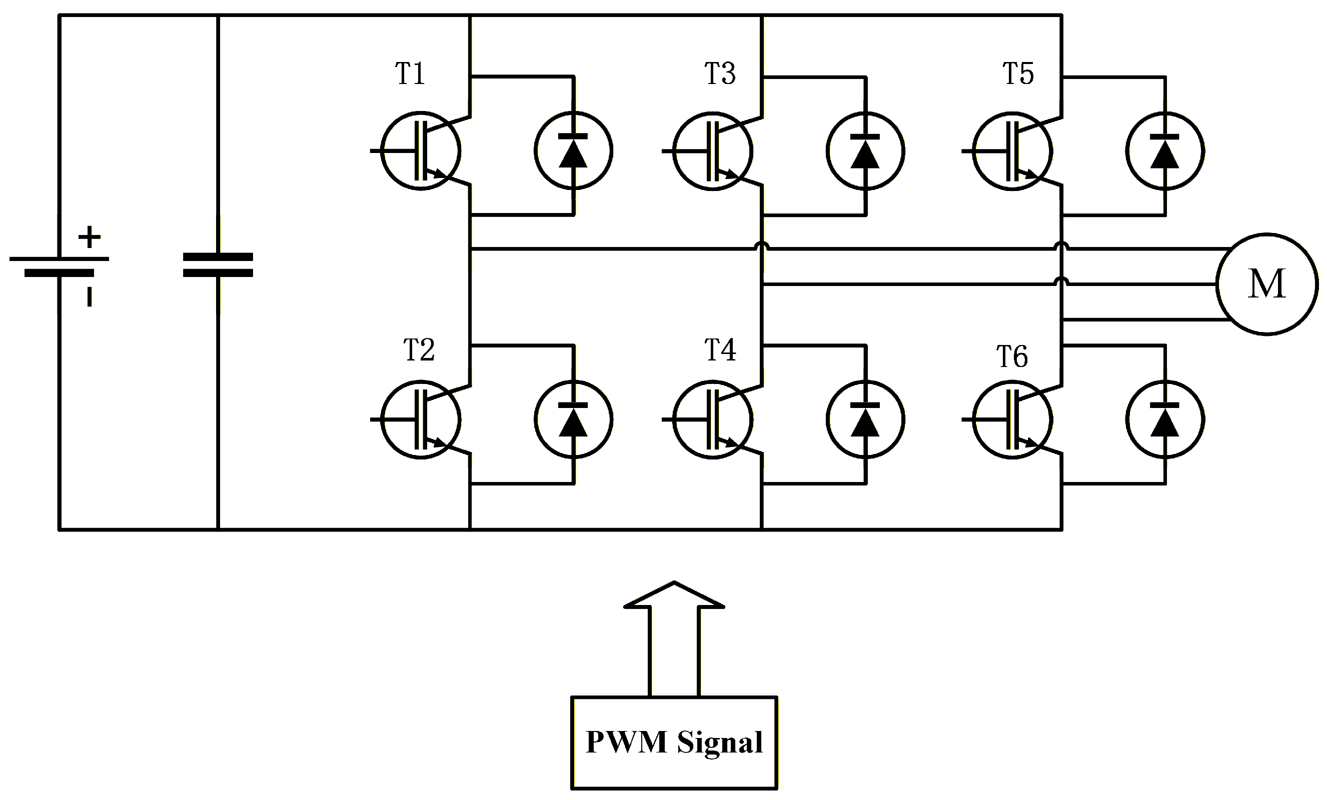
Within the space-vector pulse-width modulation (SVPWM) module of the PMSM drive, an inverter open-circuit fault is implemented by multiplying the gating-signal path with a step function. Specifically, after the multiplication operation, the gate-drive signal of the targeted MOSFET is forced to a low level at the preset time and remains low thereafter, such that the corresponding switch is effectively open-circuited. The inverter topology is shown in Figure 2.

2.4. Fault Isolation

After injecting a representative inverter fault, the coordinated control between the two motors should be disengaged immediately to prevent fault propagation. To ensure that the steering system continues to operate properly, the load torque of the faulty motor is gradually reduced to zero, while the healthy motor correspondingly increases its output torque to satisfy the steering demand. Moreover, to preserve dynamic stability during this reconfiguration, the fault-isolation process should meet three key requirements: smooth operation, gradual engagement, and overall stability without inducing additional transients. Accordingly, this study designs a logarithm-based load function to enable a smooth torque transition and to maintain steering-system stability during the switching process.
y = 10 10 ln ( n + 1 ) · ln ( x + 1 ) 10 + 10 ln ( n + 1 ) · ln ( x + 1 )
where x is the current number of steps (from 0 to 11) and n denotes the sum of all the steps; and y is the current value.

3. Dual-Motor Drive Control

3.1. Motor-Stability Control Based on Super-Twisting Sliding-Mode Control

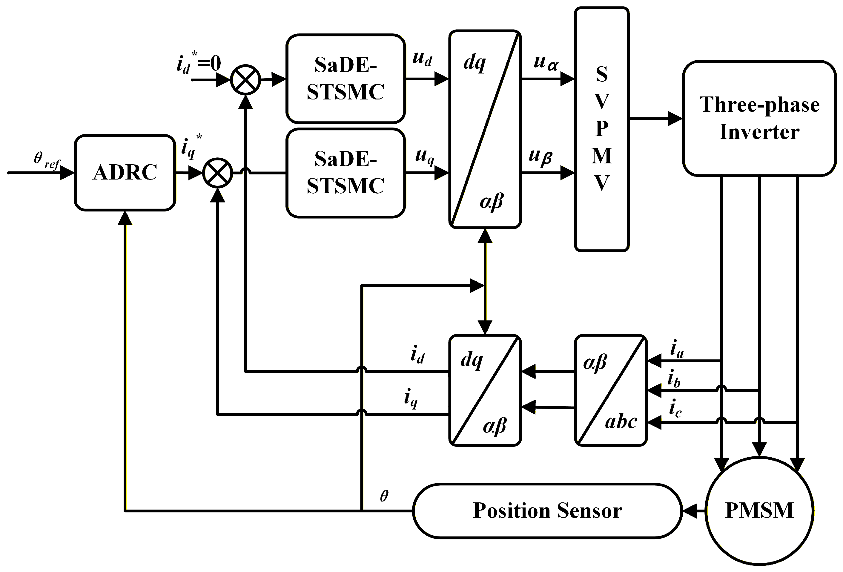
PMSMs have been used extensively with SBW because of their simplicity, efficiency, and excellent control properties. However, the PID control strategy adopted by the traditional current loop has limited their ability to inhibition external interference (such as load sudden change, current fluctuation, etc.), and shows poor robustness under the fault state, which may lead to current fluctuation aggravation, and even lead to steering failure, which seriously threatens driving safety. Consequently, this study incorporates STSMC into the current loop to guarantee that the SBW maintains its fundamental steering capability under failure circumstances. Possessing robust resilience and rapid dynamic response characteristics, the proposed control strategy alleviates fault influences upon SBW while strengthening overall stability and reliability. Figure 3 illustrates this circuit control architecture.
The stator voltage equations of the PMSM in the synchronous rotating d q reference frame can be derived from Equations (3) and (4) as follows:
u d = L d d i d d t + R i d ω e L q i q u q = L q d i q d t + R i q + ω e L d i d + ψ f
Under field-oriented control (FOC), the d-axis current is regulated to zero i d = 0 . Accordingly, the PMSM voltage model can be simplified as follows.
u d = ω e L q i q u q = L q d i q d t + R i q + ω e ψ f
Define the q-axis current tracking error as the system state variable:
e i = Δ i q = i q i q
where e i denotes the q-axis current tracking error and i q is the q-axis current reference.
The integral sliding-mode surface is selected as follows:
s = e i + α 0 t e i ( μ ) d μ
In the formula, α represents the value of the integral gain, and s denotes the variable of the sliding-mode surface.
The super-twisting reaching law of STSMC is formulated as follows:
s ˙ = γ | s | 1 2 · sign ( s ) + ν ν ˙ = β · sign ( s )
where γ > 0 and β > 0 are design parameters, ν is an auxiliary state introduced by the super-twisting algorithm, and sign ( · ) denotes the sign function.
u q = ( R α L q ) i q + ω e ψ f + L q i q + α L q i q L q γ | s | 1 / 2 sign ( s ) L q 0 t β sign ( s ) d τ
To mitigate chattering caused by the discontinuity of sign ( s ) , a saturation function is introduced within a boundary layer.
Specifically, sign ( s ) is replaced by sat ( s / ϕ ) , where ϕ > 0 denotes the boundary-layer thickness and
sat ( x ) = 1 , x > 1 , x , | x | 1 , 1 , x < 1
Stability Analysis:
The finite-time stability of the proposed super-twisting (hyper-spiral) dynamics is analyzed using Lyapunov theory.
Consider the extended Lyapunov candidate function:
V = 1 2 s 2 + 1 2 β ν 2
where β > 0 is a design parameter; thus, the time derivative of V satisfies.
V ˙ = s s ˙ + 1 β ν ν ˙
Substituting the super-twisting dynamics (with the boundary-layer approximation sat ( · ) into the above expression gives the following:
V ˙ = s s ˙ + 1 β ν ν ˙ = γ | s | 1 / 2 s · sat ( s ) + s ν ν · sat ( s )
where γ > 0 is a design parameter.
Noting that s a t ( s ) 0 and applying Young’s inequality s v 1 2 ( s 2 + v 2 ) , one obtains:
V ˙ γ | s | 1 / 2 | s · s a t ( s ) | + 1 2 s 2 + 1 2 v 2 v · s a t ( s )
By appropriate bounding and rearrangement, there exist positive constants η 1 > 0 and η 2 > 0 such that:
V ˙ η 1 | s | η 2 | v |
Consequently, one can further derive a finite-time convergence condition of the form:
V ˙ η V 1 / 2 , η > 0
which, by the finite-time stability theorem, implies that the system states reach the sliding manifold in finite time.
Stability Constraints:
Based on the above analysis, finite-time stability requires the controller parameters to satisfy the following:
γ > 0 , β > 0
Moreover, there exist strictly positive lower bounds γ min and β min , determined by the disturbance bound and the chosen boundary-layer (saturation) parameters, such that robust stability is guaranteed when:
γ γ min , β β min
Parameter Optimization Based on SADE:
Taking the stability conditions in (24)–(25) as constraints, the SADE algorithm is employed to search for the optimal parameter pair ( γ , β ) by solving the following constrained optimization problem:
min γ , β J ( γ , β )
where J ( γ , β ) is the objective function for comprehensive evaluation of the dynamic performance of the system.
Subject to
s . t . γ γ min , γ max , β β min , β max
where γ min and β min are determined by the stability analysis, while γ max and β max are selected according to practical implementation limits (e.g., actuator saturation and allowable control effort).

3.2. Synovial Parameters’ Self-Tuning

To improve dynamic performance while preserving closed-loop stability, the SADE algorithm is employed to optimize the key STSMC parameters γ and β . Compared with conventional manual tuning, SADE alleviates the difficulty of parameter calibration and enables online adaptation according to the operating conditions. Based on the Lyapunov stability analysis in Section 3.1, γ and β must satisfy the finite-time stability constraints γ γ m i n and β β m i n , where γ m i n and β m i n are theoretical lower bounds determined by the disturbance upper bound and the saturation (boundary-layer) setting. In addition, considering actuator saturation and practical implementation limits, the parameters are also bounded above by γ m a x and β m a x Therefore, the parameter-tuning task can be formulated as a constrained nonlinear optimization problem.
The optimization problem is defined as follows:
min γ , β J ( γ , β ) = 0 T ( a | e ( t ) | + b | u ( t ) | ) d t
γ m i n γ γ m a x
β m i n β β m a x
Among them, the objective function J is a comprehensive performance index, where | e ( t ) | is the absolute tracking error, | u ( t ) | is the absolute control effort, and a > 0 , b > 0 are the weight coefficients that balance the tracking accuracy and control energy consumption of the system. The integration is performed over a finite time horizon T in practical implementation. To ensure strict satisfaction of the stability conditions in optimization, a small safety margin is introduced in the constraint handling.
(1) The initial population is randomly generated within the stability-constrained search space ( [ γ m i n , γ m a x ] × [ β m i n , β m a x ] ) , where each individual vector corresponds to a candidate set of STSMC parameters.
X i = γ i , β i , i = 1 , 2 , 3 , N
where the population size is denoted by N.
(2) Fitness function: to assess the pros and cons of different types of synovium. Generally, the fitness function is used to find an optimum value for the variable coefficient of the sliding model, which can reduce the power loss and the tracking error. The target function is put forward by using the system tracing error e and
J = 0 T ( a | e ( t ) | + b | u ( t ) | ) d t
A smaller value of J indicates better performance (smaller tracking error and control effort). The weighting coefficients are set as a = 1.0 and b = 0.1 , based on preliminary tests.
This study designs the relationship between the fitness function and the objective function:
J = c f ( x ) + d
(3) Mutation and crossover: two mutation strategies, “rand//bin” and “current to b e s t / 2 / b i n , are introduced:
V i = X i 1 + F · X i 2 X i 3 V i = X i + F · X b e s t X i + F · X i 1 X i 2
In Equation (35), V i is the first individual variation vector; X i represents the first individual vector’s current position, which is the current state of the solution; X b e s t denotes the current position of the vector, the optimal individual vectors in a population that have the best fitness value in the current iteration of the individual vector; X i 1 , X i 2 and X i 3 are randomly selected from the current population of position vectors in different individual vectors, usually used to generate the difference vector; and F is the scaling factor (also known as the variation factor) that controls the scale of the difference vector.
(4) Selection: comparing the fitness of individual test vectors against current individual vectors, then choosing superior individual vectors for progression into the subsequent generation.
X i n = V i if J V i J X i X i otherwise
(5) Constraint processing: ensuring that all candidate solutions satisfy the stability constraints, a boundary-absorption strategy is employed. If any parameter of a newly generated individual vector violates its prescribed bounds, it is clipped to the nearest boundary value:
γ i = min max γ i , γ m i n , γ m a x , β i = min max β i , β m i n , β m a x
This strategy ensures that the optimization process is restricted to the admissible region of stable parameters.

4. Dual-Motor Synchronous Control

4.1. Fuzzy-PID Control

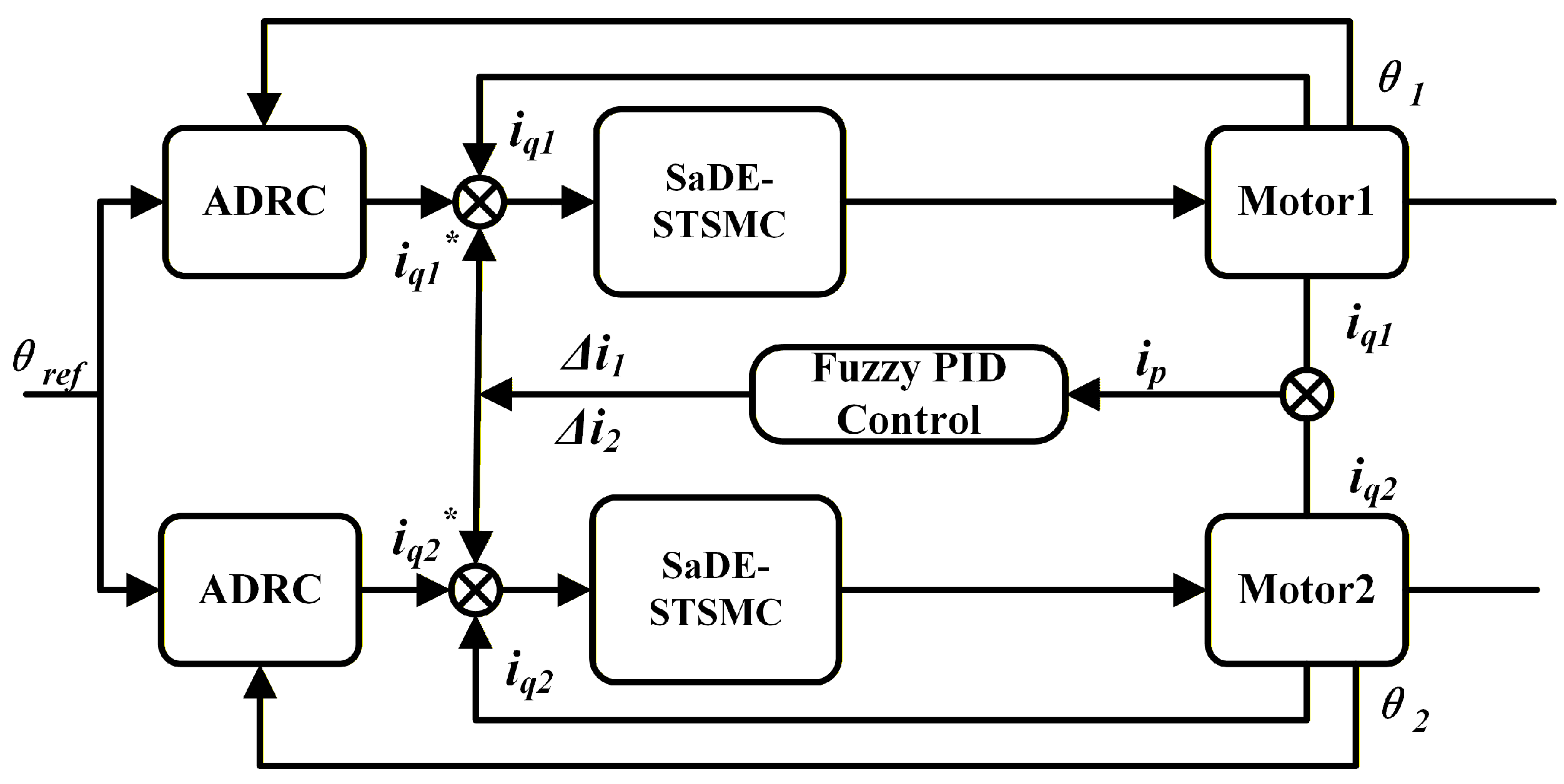
Since the single-motor driving system can be operated by wire, it cannot work properly when it breaks down. A dual-motor-synchronization approach is utilized, which elevates system reliability while simultaneously reducing individual motor load and prolonging motor operational lifespan. Within the SBW dual-motor steering system, dual motors featuring a parallel architecture propel the steering rack via independent gear pairs to constitute a mechanical–electrical composite coupling system, necessitating strict maintenance of dual-motor torque and speed synchronization. However, because the structure of the two driving motors cannot be completely consistent, coupled with the influence of load disturbance, current mutation, and other factors, the output moment of dual motors is always different. To guarantee the same output moment of dual motor, the average deviation coupling is introduced in the current loop. Through dynamic current compensation, the current difference between the two motors is effectively reduced to achieve the output torque balance. Figure 4 illustrates the control frame of the synchronization control system.
It can be seen that when two motor currents have a difference, compensation will be added by the coupling controller.
The average current of the two motors:
i p = i q 1 + i q 2 2
where i q 1 , i q 2 are the two motor currents and i p represents the average current. Motor current from both motors serves as the input, while mean current functions as the system output.
The definition of error e j ( t ) ( j = 1 , 2 ) is as follows:
e j ( t ) = i p i q = i q 1 + i q 2 2 i q
From the above Equation
e 1 ( t ) = i p i q 1 e 2 ( t ) = i p i q 2
PID control output u ( t ) is as follows:
u ( t ) = K p e j ( t ) + K i e j ( t ) d t + K d d e j ( t ) d t
where K p denotes proportional gain; K i denotes integral gain; and K d denotes differential gain.
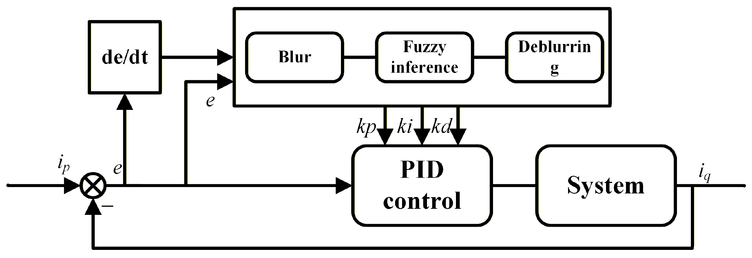
As depicted in Figure 5, the fuzzy controller predominantly comprises three essential elements: fuzzification, fuzzy inference, and defuzzification. The system first performs fuzzification on two input variables ( e 1 and e 2 ). Their respective fields are [−3, 3]. The theory domain of K p , K i , K d is [0.1, 5.0], [0.05, 2.0], and [0.001, 0.1], respectively. The fuzzy subset is NB, NM, NS, Z, PS, PM, and PB.
The proposed system utilizes three membership function types: Z-type, triangular, and S-type. The trigonometric membership function formula is as follows:
f ( x , a , b , c ) = 0 x a x a b a a x b c x c b b x c 0 x c
Using Table 1, calculate the output of K p , K i , K d and membership (the membership degree of output integration), which allows us to calculate the output value in the theory field, and realizes the parameter self-tuning.

4.2. Stability Analysis

4.2.1. Dynamic Equation of Closed Loop System

Considering that the PMSM is operated under field-oriented control with the d-axis current regulated to zero ( i d = 0 ), the q-axis current dynamics of each motor can be written as
L q d i q j d t + R i q j = u j ω e ψ f , j = 1 , 2
where u j represents the control voltage of the motor j and i q j is the measured q-axis current of motor j. The synchronous tracking error for each motor is defined as
e j = i p i q j
where i p is the q-axis current reference. The fuzzy-PID control law adopted in this paper is given by
u j = K p e j , e ˙ j e j + K i e j , e ˙ j 0 t e j ( τ ) d τ + K d e j , e ˙ j e ˙ j
where K p ( · ) , K i ( · ) , and K d ( · ) are time-varying gains adjusted online by the fuzzy controller according to the error e j in tracking i p and its derivative e ˙ j .

4.2.2. Fuzzy-Gain Constraint

According to the fuzzy rules designed in Section 4.1, the controller gains are constrained as follows:
0 < K p , min K p ( e j , e ˙ j ) K p , max 0 < K i , min K i ( e j , e ˙ j ) K i , max 0 < K d , min K d ( e j , e ˙ j ) K d , max
where K p , m i n , K p , m a x , K i , m i n , K i , m a x , K d , m i n , and K d , m a x denote the lower and upper bounds of the fuzzy-tuned PID gains. In addition, the smooth design of the fuzzy membership functions and rule base ensures that the gain variation rates are bounded, i.e.,
K ˙ p ρ p , K ˙ i ρ i , K ˙ d ρ d
In the formula, ρ p , ρ i and ρ d represent the upper bound of K p , K i and K d .

4.2.3. Stability Theorem and Proof

Consider the dual-motor system in (43) under the fuzzy-PID control law in (45). Suppose that the fuzzy-tuned gains satisfy the magnitude and rate constraints in (46)–(47), and that the motor parameters satisfy R + K p , m i n > ρ d / 2 , where ρ d denotes the upper bound on | K ˙ d | . Then, there exist positive constants λ f > 0 and α f > 0 such that the synchronization-error indices of the closed-loop system converge to zero, i.e.,
lim t e j ( t ) = 0 , lim t 0 t e j ( τ ) d τ = 0 , j = 1 , 2
Proof. 
Consider the following Lyapunov candidate function:
V f = j = 1 2 1 2 L q e j 2 + λ f 2 0 t e j ( τ ) d τ 2 + 1 2 K d e j , e ˙ j e ˙ j 2
where λ f > 0 is a design parameter.
Taking the time derivative of V f yields the following:
V ˙ f = j = 1 2 L q e j e ˙ j + λ f e j 0 t e j d τ + K d e j , e ˙ j e ˙ j e ¨ j + 1 2 K ˙ d e j , e ˙ j e ˙ j 2
Substituting the control law (45) into the motor dynamics leads to the error dynamics
L q e ˙ j = L q i ˙ p + R i p R i q j K p e j , e ˙ j e j + K i e j , e ˙ j 0 t e j d τ + K d e j , e ˙ j e ˙ j
Differentiating (51) and substituting the resulting e ¨ j into (50), and further applying the fuzzy-gain constraints (46)–(47), V ˙ f can be upper-bounded as follows:
V ˙ f j = 1 2 R + K p , m i n ρ d 2 e j 2 + λ f K i , m i n 0 t e j ( τ ) d τ 2 + j = 1 2 L q 2 i ˙ p 2 + R 2 2 L q i p 2
Since the reference current i p ( t ) and its time derivative i ˙ p ( t ) are bounded in practical steering operation, there exists a constant M > 0 such that
L q 2 i ˙ p 2 + R 2 2 L q i p 2 M
Choose the design parameter λ f as
λ f = R + K p , m i n ρ d / 2 K i , m i n
which cancels the cross terms in V ˙ f and facilitates a compact bound on the Lyapunov derivative.
With (53) and the choice of λ f in (54), inequality (52) can be further simplified to
V ˙ f α f V f + 2 M
where α f > 0 is given by
α f = min 2 R + K p , m i n ρ d / 2 L q , 2 K i , m i n > 0
By the comparison lemma, the differential inequality (55) implies
V f ( t ) V f ( 0 ) e α f t + 2 M α f 1 e α f t
Hence, V f ( t ) is uniformly ultimately bounded. Moreover, whenever V f ( t ) > 2 M α f , (55) yields V ˙ f ( t ) < 0 , which implies that the system trajectories enter and remain in the compact set.
Within the invariant set Ω , introduce the auxiliary function
W = 1 2 e 1 2 + e 2 2
By differentiating W along the trajectories of the error dynamics and using the stability condition R + K p , m i n ρ d / 2 > 0 , one obtains the following bound:
W ˙ 2 R + K p , m i n ρ d / 2 L q W
Therefore, e 1 and e 2 converge exponentially to zero within Ω . Moreover, by (51), the corresponding integral error term is bounded and convergent, completing the stability analysis. □

4.2.4. Verification of Stability Conditions

For the PMSM considered in this study, the nominal parameters are R = 0.958 Ω and L q = 3.95 × 10 4 H . The minimum fuzzy proportional gain is selected as K p , m i n = 0.1 and K i , m i n = 0.05 , and the upper bound on the gain variation rate is set to ρ d = 0.1 . Substituting these values into the derived stability inequalities gives
R + K p , m i n ρ d 2 = 0.958 + 0.1 0.05 = 1.008 > 0
α f = min 2 × 1.008 0.000395 , 2 × 0.05 = min ( 5101.27 , 0.1 ) = 0.1 > 0
and the corresponding parameter λ f is obtained as
λ f = 1.008 0.05 = 20.16
Therefore, the above stability conditions are satisfied under the chosen parameter set, indicating that the proposed fuzzy-PID-based synchronous control scheme is stable.

5. Experimental Analysis

To validate the synchronization of fuzzy-PID control alongside the stability of SADE-STSMC, the experimental framework is partitioned into two phases: dual-motor-synchronization validation and fault-tolerance-performance validation.

5.1. Dual-Motor-Synchronization Verification

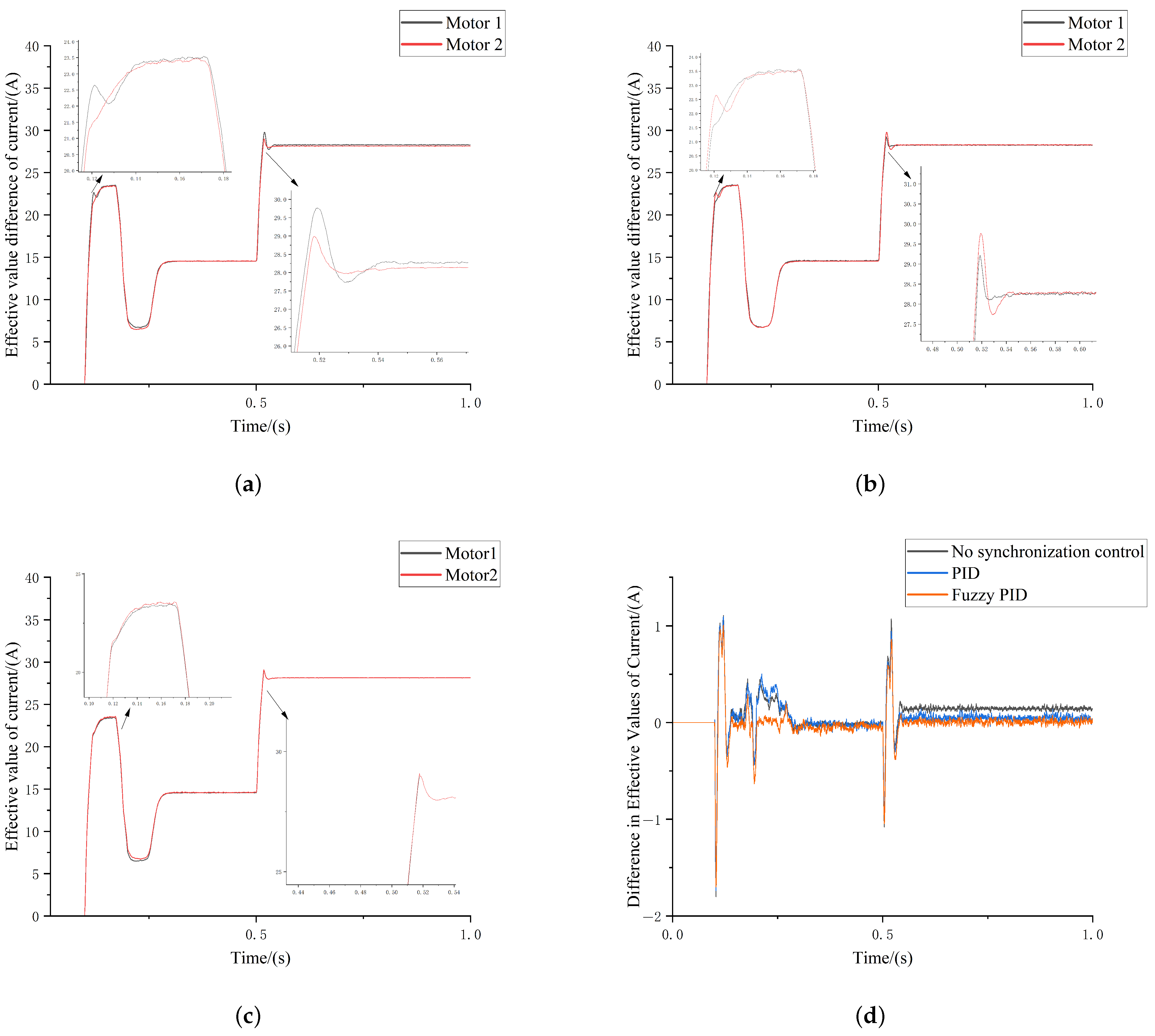
Dual-motor-synchronization performance undergoes testing through load abrupt change application under angular-step conditions and double-line-shift conditions. Load abrupt changes can effectively evaluate control system synchronization precision under dynamic operational circumstances, thereby enabling assessment of dual-motor cooperative effectiveness. The SBW system is employed to examine dual-motor performance in terms of external interference, synchronization, and dynamical characteristics. Within Carsim, the steering-wheel-angle step input is configured to 45°, the equivalent steering-execution-motor input to 720°, and vehicle speed to 60 km/h. Additionally, a load torque of 10 Nm is applied to the steering motor at 0.1 s and a load torque of 20 Nm to the steering motor at 0.5 s. Figure 6 presents the simulation outcomes.
Figure 6 and Table 2 show the current’s root mean square (RMS) difference under various conditions. As depicted in Figure 6 and Table 2, when the load suddenly changes at 0.1 s, the root mean square difference of current suddenly increases, reaching 1.85 A without synchronization. Throughout PID control, the current difference measured 1.80 A, whereas under fuzzy-PID control, the current difference substantially declined to 1.70 A. This demonstrates that fuzzy-PID control can markedly diminish current oscillations during sudden load variation scenarios; following a brief fluctuation period after the 0.1-s load alteration, the error reverts to a stable condition. Within the stable-state-absent synchronous control, the root mean square difference of current approximates 0.03 A, PID control achieves 0.02 A, and fuzzy-PID control attains 0.01 A. Upon renewed load variation at 0.5 s, the root mean square difference of current abruptly escalates, reaching −1.09 A without synchronization, −0.95 A under PID, and −0.83 A with fuzzy-PID control. Subsequent to the 0.5-s load modification, the system demonstrates momentary fluctuation before error stabilization occurs. Precisely speaking, under asynchronous control, the root mean square (RMS) difference of current concentrates near 0.15 A; this difference stands at 0.08 A for traditional PID control and 0.05 A for fuzzy-PID control (the 0.05 A difference remains negligible). Moreover, under angular-step input circumstances, regardless of steady-state-error evaluation or load-disturbance response assessment, fuzzy-PID control surpasses both traditional PID control and asynchronous control approaches in terms of dynamic response velocity and steady-state precision, effectively minimizing the disparity in motor current effective values.
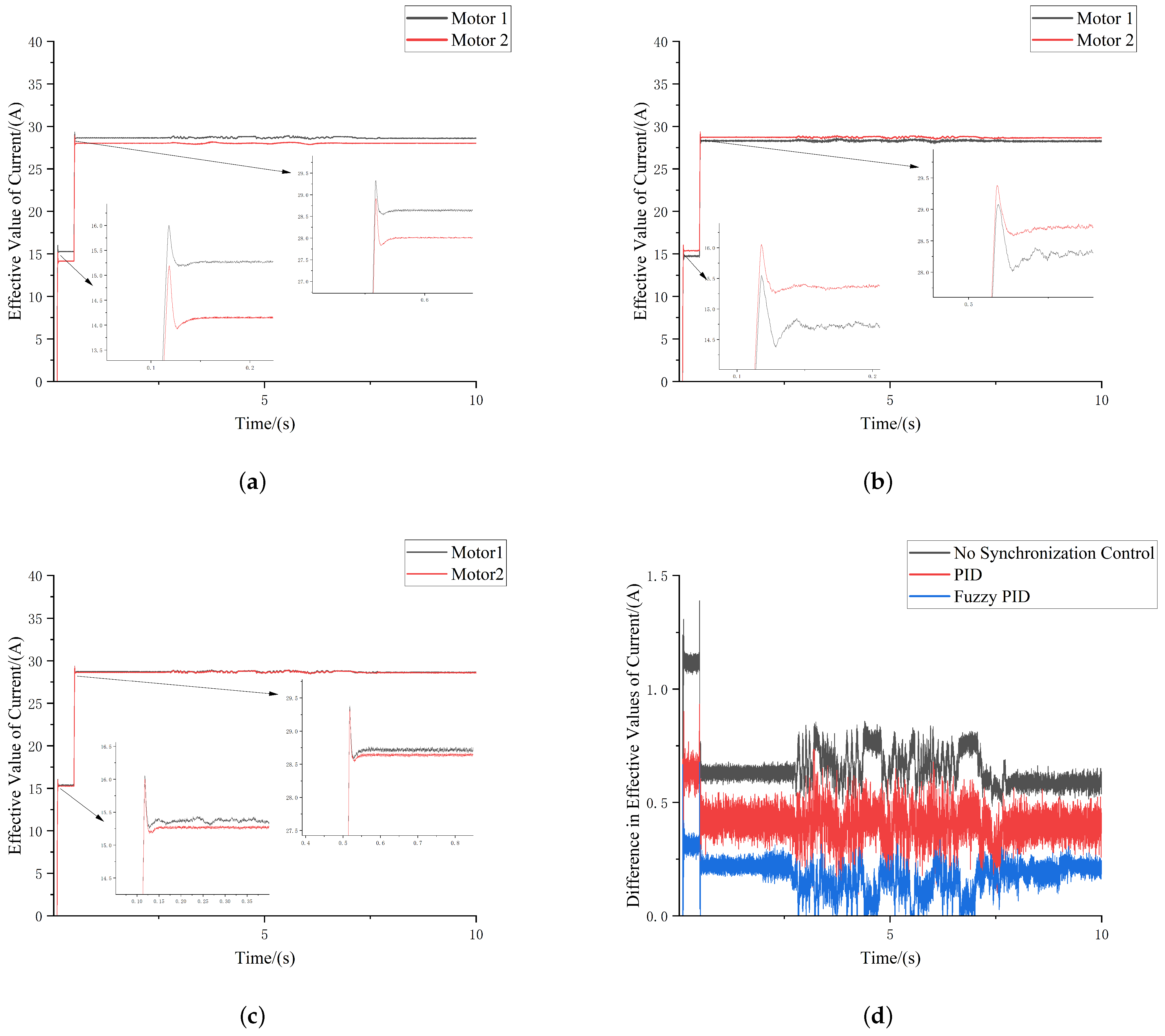
Throughout the simulation process, motor 1’s inertia force J, resistance R, and inductance L are configured to 0.75 times their nominal values, with a load torque of 10 Nm imposed upon both motors at 0.1 s. At 0.5 s, the load transitions to 20 Nm. Dual-motor synchronous response undergoes analysis. Figure 7 presents the simulation outcomes.
Based on the experimental evidence in Figure 7 and Table 3, the fuzzy-PID control strategy exhibited substantial performance advantages during two load-step transitions at 0.1 s and 0.5 s. Upon abrupt load variation, the root mean square difference of current escalates instantaneously: the current effective value difference under asynchronous control reaches 1.25 A, under PID control it measures 0.90 A, and under fuzzy-PID control attains 0.65 A. Precisely speaking, the fuzzy-PID control difference stands 48% lower than asynchronous control and 27.8% lower than PID control. Following 0.1 s of load mutation, the steady-state difference without synchronization reaches 1.15 A, PID control achieves 0.65 A, and fuzzy-PID control obtains 0.30 A, representing a 73.9% reduction compared to asynchronous control and 53.8% reduction compared to PID control. Upon load transition at 0.5 s, the effective value difference of current without synchronous control measures 1.40 A, PID control achieves 0.95 A, and fuzzy-PID control attains 0.68 A, demonstrating 51.4% less than asynchronous control and 28.4% less than PID control. Following 0.5 s load mutation, the steady-state difference without synchronization reaches 0.70 A, PID control achieves 0.46 A, and fuzzy-PID control records 0.15 A, representing a 78.6% decrease compared to asynchronous control and a 67.4% decrease compared to PID control. The experimental outcomes reveal that under double-line-shifting circumstances, simulation results indicate that relative to traditional PID or asynchronous control approaches, fuzzy-PID control can diminish the root mean square difference of transient current during load transients by 27.8% to 51.43%, and diminish steady-state error by 53.8% to 78.6%, thereby substantially minimizing the effective value fluctuation of motor current.

5.2. Fault-Tolerant Performance Verification

During the synchronous operation of dual motors, a fault is injected into one of the motors to simulate the inverter fault. Through the fault injection experiment, the stability of the SADE-STSMC under the fault state and its ability to suppress the influence of the faulty motor are mainly verified. The specific issue is that the faulty motor can maintain stable operation under the SADE-STSMC to avoid being out-of-step or out-of-control; the nonfaulty motor is less affected by the faulty motor and can continue to maintain high-precision synchronous-steering operation.
The inverter open-circuit fault studied in this paper refers to a single-bridge open-circuit fault, which relates to a partial loss of control effectiveness, and is significantly different from gradual faults such as bias and drift. In simulation and experiments, this fault is realized by directly cutting off the driving signal of the faulty phase, which is equivalent to a partial loss of effectiveness in the corresponding control input channel. The phase current of the motor decreases gradually, and its fault characteristics have been reflected in the system-state response and experimental design.
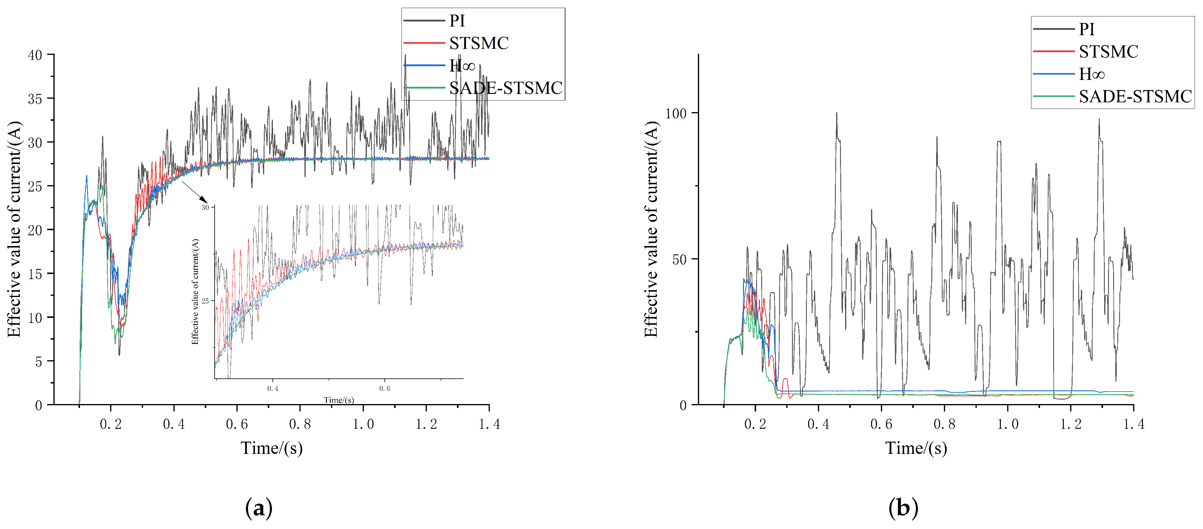
The SADE-STSMC of the present motor has been studied. To show the robustness of this approach, fault injection is carried out on PI control, STSMC, H robust control, and SADE-STSMC under angular-step conditions. Both motors received 10 Nm load for 0.1 s before fault injection. Perform fault injection and cut off coordinated control at 0.15 s. By 0.2 s, the faulty motor’s torque drops to zero as the healthy motor increases to 20 Nm for steering. Figure 8 presents both the working and broken motors’ RMS currents. Figure 8 illustrates the comparison of current RMS between the normal motor and fault motor when employing different control strategies under 0.15 s fault injection circumstances.
Based on the experimental data in Figure 8a and Table 4, the performance variations of the four control algorithms for the healthy motor under dynamic conditions are presented as follows. The traditional PI control exhibits the worst performance under double interference, with a maximum current peak of 39.75 A, a stabilization time of 1.4 s, and continuous divergence after the load mutation. The STSMC algorithm shows good robustness, reducing the maximum peak to 28.11 A and shortening the stabilization time to 0.6 s, but still suffers from high-frequency chattering. The H robust control achieves comprehensive performance superior to PI and STSMC, with a maximum current peak of 27.92 A, a stabilization time of 0.55 s, and significantly reduced chattering compared with the STSMC. The proposed SADE-STSMC algorithm delivers the best overall performance, not only further reducing the maximum peak to 24.86 A, but also requiring only 0.5 s for stabilization, with no overshoot or oscillation throughout the process.
The experimental evidence in Figure 8b and Table 4 demonstrates the performance disparities among the four control strategies under motor-fault conditions. The traditional PI control exhibits the poorest performance, characterized by sluggish system response (stabilization time: 1.4 s) and severe fluctuations (maximum fluctuation: 101.2 A), posing a risk of secondary failure. The STSMC significantly improves the system robustness, reducing the maximum peak to 37.83 A and shortening the stabilization time to 0.33 s. The H robust control outperforms STSMC in fault suppression capability, with a maximum peak of 32.15 A and a stabilization time of 0.30 s. In contrast, the SADE-STSMC control achieves the optimal performance, not only further reducing the maximum peak by 26.28% to 27.89 A, but also shortening the stabilization time to 0.27 s, completely eliminating the current impact and chattering caused by the fault.
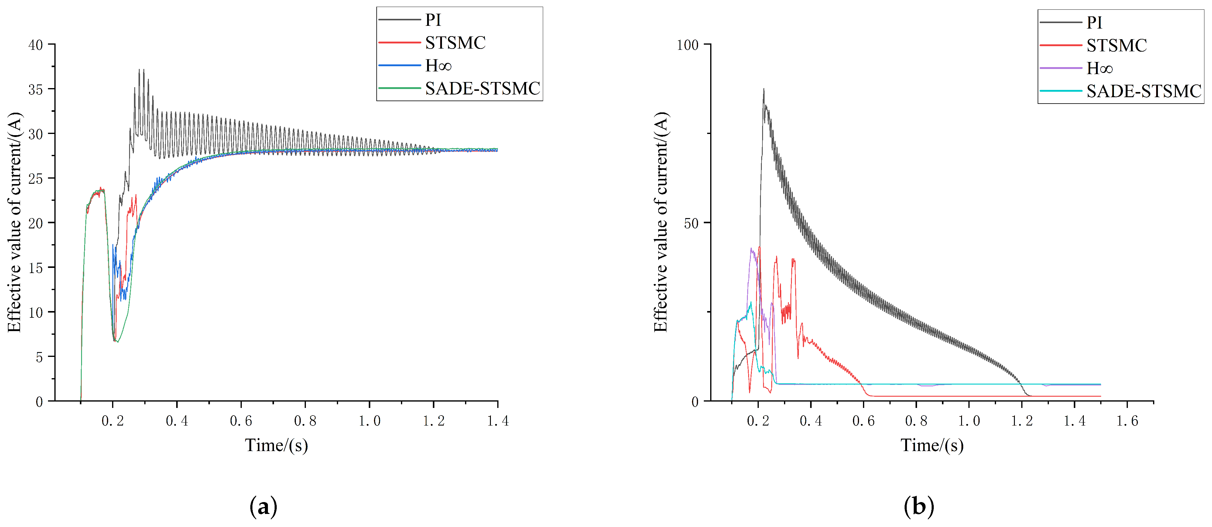
For the dual-motor system, the load torque reaches 10 Nm at 0.1 s. At 0.2 s, fault injection is performed, at which point the coordinated control strategy is deactivated. To minimize faulty motor impact to the maximum extent, the faulty motor’s load torque undergoes gradual reduction to 0 by 0.25 s, whereas the normal motor’s load torque increases to 20 Nm to satisfy steering system requirements. Figure 9 depicts the RMS current between a normal motor and a faulty motor.
In Figure 9, Table 5 illustrates the comparison of current RMS between the normal motor and the faulty motor, employing different control strategies under 0.2 s fault-injection circumstances.
Based on the experimental data presented in Figure 9a and Table 5, the four control strategies exhibit obvious gradient differences in terms of performance, with respect to the normal motor. Specifically, the traditional PI control shows poor dynamic characteristics, its maximum current peak reaches 36.7 A, and it takes a long time (1 s) to restore the stable state; the STSMC shows better robustness, reducing the maximum current peak to 28.6 A, and reducing the stability time to 0.55 s, but there is still obvious control chattering phenomenon; H robust control achieves comprehensive performance superior to PI and STSMC, with a maximum current peak of 27.6 A, a stability time of 0.6 s, and significantly reduced chattering compared with the STSMC. In contrast, the SADE-STSMC control strategy achieves the optimal comprehensive performance, which not only further reduces the maximum current peak to 27.5 A (25.1% lower than PI and 3.8% lower than STSMC), but also shortens the stability time to 0.5 s (50% higher than PI, 9.1% higher than STSMC, and 16.7% higher than H robust control).
Based on the experimental evidence in Figure 9b and Table 5, the performance among the four control strategies exhibits substantial variation under motor-fault circumstances: traditional PI control generates a maximum current peak of 83.25 A, with a stability time of 1 s, and presents a risk of secondary fault; the STSMC control reduced the maximum peak to 32.36 A and the stability time to 0.32 s, but there was still transitional oscillation; and H robust control outperforms the STSMC in fault suppression capability, with a maximum peak of 42.8 A and a stability time of 0.26 s. The SADE-STSMC control performance is the best: the maximum peak is further reduced to 24.53 A (70.5% lower than PI, 24.2% lower than STSMC, and 42.7% lower than H robust control), the stability time is only 0.26 s (74% higher than PI and 18.8% higher than STSMC), and the steady-state oscillation is completely eliminated.
Experimental outcomes reveal that, relative to the PI, standard STSMC and H robust control approaches, the SADE-STSMC control strategy demonstrates superior performance. Through its innovative adaptive mechanism, this method has significant improvements in terms of three key aspects: dynamic response characteristics, system stability maintenance, and anti-interference ability. These comprehensive advantages make SADE-STSMC a more reliable and effective solution for motor control systems, especially in fault-prone operating environments where the requirements for performance and operational reliability are consistent.
It is particularly noteworthy that the experimental data reveal the key impact of fault injection timing: Figure 8 (early-stage malfunction during steering process) shows that the anti-interference ability of the system under dynamic steering conditions faces greater challenges, while Figure 9 (malfunction near the end of steering) shows that the recovery ability of the system in the stable phase is also crucial. Compared with PI, traditional STSMC and H robust control, the SADE-STSMC maintains excellent performance under the fault conditions of these two different stages, which verifies the effectiveness of its adaptive mechanism—it cannot only quickly respond to the serious disturbance in the steering process, but can also accurately preserve the system’s stability at the end of the steering.
When one motor suffers complete failure due to an inverter open-circuit fault, the remaining healthy motor can only sustain the basic steering functionality to guarantee minimum operational safety of the vehicle, with noticeable degradation in closed-loop control performance. Specifically, constrained by the rated power and torque capacity of a single actuator, the healthy motor cannot provide the equivalent output capability of dual-motor coordinated operation, leading to deteriorated dynamic response and reduced tracking precision, particularly under demanding conditions including large-angle steering, high-load shocks, and high-speed driving.
The proposed control scheme is developed primarily for single-motor single-bridge open-circuit fault scenarios, and can only mitigate fault-induced current surges and synchronization errors within a restricted range. A key limitation of this work lies in the lack of in-depth investigation into the system-performance-degradation mechanism after the healthy motor undertakes the full steering torque, which means the proposed strategy cannot effectively compensate for the performance loss caused by single-motor actuation. Furthermore, its control performance still requires improvement under extreme conditions such as simultaneous failure of both motors, drastic load variations, and complex road disturbances. Future work will focus on developing performance recovery and advanced robust fault-tolerant control schemes dedicated to single-motor actuation, aiming to further enhance the overall reliability and fault-tolerance capability of the steer-by-wire system.

6. Conclusions

An effective solution has been furnished to tackle the two core challenges within the wire-controlled steering system: initially, elevated consistency of dual-motor output is secured through torque synchronization control, thereby improving fundamental system performance and reliability; subsequently, advanced fault-tolerant control strategies guarantee functional safety during fault scenarios, strengthening system robustness. These two dimensions operate synergistically to deliver crucial technical support for constructing a safer and more efficient next-generation steer-by-wire system.
Initially, an innovative torque synchronization control strategy grounded in current was introduced, with a fuzzy-PID controller designed for its implementation. Experimental validation was performed through corner-step and double-shift-line circumstances: under corner-step circumstances, this control strategy diminished the peak root mean square difference of current by 8.1% to 23.9% and the steady-state difference by 66% and under double-line-shifting circumstances, the peak transient difference declined by 27.8% to 51.43%, and the steady-state difference declined by 53.8% to 78.6%. Experimental outcomes show that the suggested fuzzy-PID control strategy can successfully dampen brief shocks and substantially enhance steady-state precision across various operational scenarios. This confirms that dual motors can sustain highly consistent torque output over extended periods, preventing efficiency loss and potential wear arising from internal deviations.
Secondly, the innovative SADE-STSMC control strategy for the current loop is proposed, demonstrating excellent comprehensive performance under fault conditions. The SADE-STSMC strategy maintains optimal performance over different fault injection times: compared with PI, the maximum peak current during steering was reduced by 37.5%, and the stabilization time was shortened by 71.4%; the peak value at the turning end decreased by 70.5%, and the stabilization time was shortened by 74%. Compared with STSMC, it further reduces the peak by 24.2% and basically eliminates the jitter phenomenon. Meanwhile, comparative experiments with the classical H robust control verify that the proposed method also has obvious advantages in current tracking, convergence speed and fault suppression capability. Specifically, under motor fault conditions, compared with H control, the maximum current peak of the faulty motor is reduced by 42.7%, the stabilization time of the healthy motor is shortened by 16.7%, and current chattering is completely eliminated. The experimental results show that the SADE-STSMC strategy has verified its superior dynamic performance, smooth control quality, and robustness, which together provide reliable guarantees for system safety.
The control strategy of this study has been mainly validated for its effectiveness through simulation experiments. Future work will focus on building high-precision physical test benches, applying the proposed fuzzy-PID and SADE-STSMC strategies to real motors and actuators to further test their performance, durability, and engineering applicability in complex physical environments, and promote their transformation from theoretical models to engineering applications.

Author Contributions

J.L.: Resources, supervision. Y.Z.: Conceptualization, methodology and writing—original manuscript preparation. X.X.: Revision of mathematical derivations. Z.Y.: Review of the results. T.Z.: Investigation. All authors have read and agreed to the published version of the manuscript.

Funding

This research received no external funding.

Data Availability Statement

The data that support the findings of this study are available from the corresponding author upon reasonable request.

Conflicts of Interest

Author Xinfu Xu and Yazhou Zhou were employed by the company Nexteer Automotive Systems (Suzhou) Co., Ltd. The remaining authors declare that the research was conducted in the absence of any commercial or financial relationships that could be construed as a potential conflict of interest.

References

  1. Huang, C.; Naghdy, F.; Du, H.; Huang, H. Fault tolerant steer-by-wire systems: An overview. Annu. Rev. Control 2019, 47, 98–111. [Google Scholar] [CrossRef]
  2. Luo, L.; Li, W.; Gao, D.; Meng, Y. A Review of Software and Hardware Fault Tolerance Research in Steer-by-Wire Systems. Automob. Parts 2019, 8, 83–89. [Google Scholar] [CrossRef]
  3. Xu, K.; Wang, C.; Zhao, W.; Luan, Z.; Liang, W.; Zhang, S.; Zhang, Z. Event-Triggered Adaptive Fuzzy Switching Fault-Tolerant Control of Dual-Motor Steer-by-Wire System Considering Load Fluctuation and Limited Communication Bandwidth. IEEE Trans. Fuzzy Syst. 2024, 32, 4086–4098. [Google Scholar] [CrossRef]
  4. Shi, G.B.; Guo, C.; Wang, S.; Liu, T.Y. Angle Tracking and Fault-Tolerant Control of Steer-by-Wire System With Dual Three-Phase Motor for Autonomous Vehicle. IEEE Trans. Intell. Transp. Syst. 2024, 25, 5842–5853. [Google Scholar] [CrossRef]
  5. He, L.; Chen, G.; Zheng, H. Fault tolerant control method of dual steering actuator motors for steer-by-wire system. Int. J. Automot. Technol. 2015, 16, 977–987. [Google Scholar] [CrossRef]
  6. Poudel, B.; Giri, N.; Munir, A. Design and comparative evaluation of GPGPU- and FPGA-based MPSoC ECU architectures for secure, dependable, and real-time automotive CPS. In Proceedings of the 2017 IEEE 28th International Conference on Application-Specific Systems, Architectures and Processors (ASAP), Seattle, WA, USA, 10–12 July 2017. [Google Scholar]
  7. Meléndez-Useros, M.; Viadero-Monasterio, F.; Jiménez-Salas, M.; López-Boada, M.J. Active steering fault diagnosis via integrated LSTM-based sensor detection and robust actuator fault estimation. Reliab. Eng. Syst. Saf. 2026, 265, 111573. [Google Scholar] [CrossRef]
  8. Yang, C.; Wang, Q.; Wang, W.; Gao, Y.; Zhang, Y.; Zhang, R. A fault estimation and fault-tolerant operation scheme design under simultaneous actuator and sensor faults for steer-by-wire system. Veh. Syst. Dyn. 2025, 1–28. [Google Scholar] [CrossRef]
  9. Zhu, B.; Lü, T.; Zhao, J.; Chen, Z.; Wu, J. Fault Diagnosis and Fault-tolerance Strategy of Current Sensor for Redundant Steering System. J. Mech. Eng. 2024, 60, 413–424. [Google Scholar] [CrossRef]
  10. Guo, Z.; Li, J.; Yan, M.; Wang, G. Composite speed control based on an improved gain-adaptive super-twisting sliding mode observer for a permanent magnet synchronous motor. Control Eng. Pract. 2025, 157, 106241. [Google Scholar] [CrossRef]
  11. Teng, Y.; Gao, Q.; Chen, X.; Xu, D. Design of Lumped Disturbance Observer in Current Loop of IPMSM Based on Recursive Integral Sliding Mode Surface. Energies 2024, 17, 836. [Google Scholar] [CrossRef]
  12. Zhang, S.; Shen, A.; Luo, X.; Tang, Q.; Li, Z. Multi-sliding mode current disturbance suppression scheme based model reference adaptive system for sensorless control of permanent magnet synchronous motor. ISA Trans. 2023, 137, 615–628. [Google Scholar] [CrossRef]
  13. Chen, Z.; Zhang, X.; Liu, C.; Ren, J.; Guo, H. Research on Current Decoupling and Harmonic Suppression Strategies for Permanent Magnet Synchronous Motors Based on Proportional Resonant Active Disturbance Rejection Control. Chin. J. Electr. Eng. 2022, 42, 9062–9071. [Google Scholar]
  14. Gao, H. Vehicle PMSM Model Predictive Control Based on Variable Structure Active Disturbance Rejection. Comput. Appl. Softw. 2018, 35, 83–87, 137. [Google Scholar]
  15. Zhong, G.; Wang, C.; Dou, W. Fuzzy Adaptive PID Fast Terminal Sliding Mode Controller for a Redundant Manipulator. Mech. Syst. Signal Process. 2021, 159, 107577. [Google Scholar] [CrossRef]
  16. Sun, X.; Cai, Y.; Wang, S.; Liu, Y.; Chen, L. A hybrid approach to modeling and control of vehicle height for electronically controlled air suspension. Chin. J. Mech. Eng. 2016, 29, 152–162. [Google Scholar] [CrossRef]
  17. Luo, J.; Wang, L.; Liu, B. Low-speed control of PMSM based on ADRC + FOPID. Syst. Sci. Control Eng. 2021, 9, 73–87. [Google Scholar] [CrossRef]
  18. Tang, L.; Wang, W.; Zhang, C.; Wang, Z.; Ge, Z.; Yuan, S. Linear Active Disturbance Rejection Control System for the Travel Speed of an Electric Reel Sprinkling Irrigation Machine. Agriculture 2024, 14, 1544. [Google Scholar] [CrossRef]
  19. Matraji, I.; Al-Durra, A.; Haryono, A.; Al-Wahedi, K.; Abou-Khousa, M. Trajectory tracking control of Skid-Steered Mobile Robot based on adaptive Second Order Sliding Mode Control. Control Eng. Pract. 2018, 72, 167–176. [Google Scholar] [CrossRef]
  20. Sun, J.; Wang, Z.; Ding, S.; Xia, J.; Xing, G. Adaptive disturbance observer-based fixed time nonsingular terminal sliding mode control for path-tracking of unmanned agricultural tractors. Biosyst. Eng. 2024, 246, 96–109. [Google Scholar] [CrossRef]
  21. Liu, J.; Gao, L.; Zhang, J.; Yan, F. Super-twisting algorithm second-order sliding mode control for collision avoidance system based on active front steering and direct yaw moment control. Proc. Inst. Mech. Eng. Part J. Automob. Eng. 2021, 235, 43–54. [Google Scholar] [CrossRef]
  22. Muduli, U.R.; Beig, A.R.; Al Jaafari, K.; Alsawalhi, J.Y.; Behera, R.K. Interrupt-Free Operation of Dual-Motor Four-Wheel Drive Electric Vehicle Under Inverter Failure. IEEE Trans. Transp. Electrif. 2021, 7, 329–338. [Google Scholar] [CrossRef]
  23. El-samahy, A.; Shamseldin, M. Brushless DC motor tracking control using self-tuning fuzzy PID control and model reference adaptive control. Ain Shams Eng. J. 2018, 9, 341–352. [Google Scholar] [CrossRef]
  24. Colombo, L.; Corradini, M.L.; Cristofaro, A.; Ippoliti, G.; Orlando, G. An Embedded Strategy for Online Identification of PMSM Parameters and Sensorless Control. IEEE Trans. Control Syst. Technol. 2019, 27, 2444–2452. [Google Scholar] [CrossRef]
  25. Huang, H.; Xu, K.; Wang, C.; Zhao, W.; Luan, Z.; Xu, J.; Sun, H. Vehicle Stability and Synchronization Control of Dual-Motor Steer-by-Wire System Considering Time-Varying CAN Network Time Delay. IEEE Trans. Autom. Sci. Eng. 2026, 23, 6789–6801. [Google Scholar] [CrossRef]
  26. Zou, S.; Zhao, W.; Wang, C.; Liang, W.; Chen, F. Tracking and Synchronization Control Strategy of Vehicle Dual-Motor Steer-by-Wire System via Active Disturbance Rejection Control. IEEE/Asme Trans. Mechatron. 2023, 28, 92–103. [Google Scholar] [CrossRef]
  27. Hwang, H.; Choi, H.; Nam, K. Practical Synchronous Steering Angle Control of a Dual-Motor Driving Steer-by-Wire System. IEEE Access 2019, 7, 133100–133110. [Google Scholar] [CrossRef]
  28. Hua, M.; Chen, G.; Zong, C.; He, L. Research on Synchronous Control Strategy of Steer-By-Wire System with Dual Steering Actuator Motors. Int. J. Veh. Auton. Syst. 2020, 15, 50–76. [Google Scholar] [CrossRef]
  29. Chen, G.; Li, L. A Dual Motor Embedded Synchronous System Based on Sliding Mode Control. Electron. Des. Eng. 2024, 32, 134–138. [Google Scholar]
Figure 1. Overall structure of the dual-motor SBW system.
Machines 14 00495 g001
Figure 2. Inverter structure.
Machines 14 00495 g002
Figure 3. Current loop control structure.
Machines 14 00495 g003
Figure 4. Synchronous control system.
Machines 14 00495 g004
Figure 5. Fuzzy-PID control.
Machines 14 00495 g005
Figure 6. Synchronous response under angular-step conditions: (a) nonsynchronous control; (b) PID control; (c) Fuzzy-PID control; and (d) synchro error.
Machines 14 00495 g006
Figure 7. Synchronous response under double-line-shift conditions: (a) nonsynchronous control; (b) PID control; (c) fuzzy-PID control; and (d) synchro error.
Machines 14 00495 g007
Figure 8. Effective current value under the fault in the early stage of steering: (a) normal motor; and (b) faulty motor.
Machines 14 00495 g008
Figure 9. Effective current value under faults in the later stage of steering: (a) normal motor; and (b) faulty motor.
Machines 14 00495 g009
Table 1. K p , K i , K d Fuzzy Rule Table.
NBNMNSZPSPMPB
NBPB/NB/PSPM/NB/PSPM/NM/ZPS/NM/ZPS/NS/ZZ/Z/NSZ/Z/NM
NMPM/NB/PSPM/NM/ZPS/NM/ZPS/NS/ZZ/Z/NSZ/Z/NMNS/Z/NM
NSPM/NM/ZPS/NS/ZPS/NS/ZZ/Z/NSZ/Z/NMNS/Z/NMNS/PS/NM
ZPS/NM/ZPS/NS/ZZ/Z/NSZ/Z/NMNS/Z/NMNS/PS/NMNM/PS/NM
PSPS/NS/ZZ/Z/NSZ/Z/NMNS/Z/NMNS/PS/NMNM/PS/NMNM/PM/NM
PMZ/Z/NSZ/Z/NMNS/Z/NMNS/PS/NMNM/PS/NMNM/PM/NMNB/PM/NS
PBZ/Z/NMNS/Z/NMNS/Z/NMNS/PS/NMNM/PM/NMNB/PM/NSNB/PB/NS
Table 2. RMS Difference of Current under Angular-Step Conditions.
Dual-Motor Current
Error/(A)
0.1 s Load MutationSteady-State
Difference
0.5 s Load MutationSteady-State
Difference
Nonsynchronous
control
1.850.03−1.090.15
PID control1.800.02−0.950.08
Fuzzy-PID control1.700.01−0.830.05
Table 3. RMS difference of Current under Double-Shift-Line Working Conditions.
Dual-Motor Current
Error/(A)
0.1 s Load MutationSteady-State
Difference
0.5 s Load MutationSteady-State
Difference
Nonsynchronous
control
1.251.151.400.70
PID control0.900.650.950.46
Fuzzy-PID control0.650.300.680.15
Table 4. Extracted Effective Current Data under Faults—Early Steering Stage.
Normal MotorFaulty Motor
PISTSMC H SADE-STSMCPISTSMC H SADE-STSMC
Settling Time/(s)1.40.60.550.51.40.330.280.27
Peak/(A)39.7528.1127.9224.86101.237.8332.1527.89
Table 5. Extracted Effective Current Data under Faults—Later Steering Stage.
Normal MotorFaulty Motor
PISTSMC H SADE-STSMCPISTSMC H SADE-STSMC
Settling Time/(s)10.550.60.510.320.260.26
Peak/(A)36.728.627.627.583.2532.3642.824.53
Disclaimer/Publisher’s Note: The statements, opinions and data contained in all publications are solely those of the individual author(s) and contributor(s) and not of MDPI and/or the editor(s). MDPI and/or the editor(s) disclaim responsibility for any injury to people or property resulting from any ideas, methods, instructions or products referred to in the content.