Article

Mechanical Insertion Force and Electrical Contact Resistance of By-Pass Switches with Axially Canted Coil Springs

by
Chao Zhang
1,2,
Ming Li
3,
Wanbin Ren
1,* and
Jian Liu
2
1
School of Electrical Engineering and Automation, Harbin Institute of Technology, Harbin 150001, China
2
School of Instrumentation Science and Engineering, Harbin Institute of Technology, Harbin 150001, China
3
Aviation Key Laboratory of Science and Technology on Aero Combined Environment, China Aero-Polytechnology Establishment, Beijing 100028, China
*
Author to whom correspondence should be addressed.
Machines 2025, 13(9), 878; https://doi.org/10.3390/machines13090878
Submission received: 26 August 2025 / Revised: 16 September 2025 / Accepted: 18 September 2025 / Published: 21 September 2025
(This article belongs to the Section Machine Design and Theory)

Abstract

By-pass switches play a crucial role in high-power electrical equipment, where reliable mechanical insertion and stable electrical contact are essential for safety and performance. However, few computational models have been developed to characterize the coupled mechanical–electrical behavior of by-pass switches with axially canted coil springs, which limits the understanding of their structural parameter effects. Motivated by this gap, this work investigates the mechanical insertion force and electrical contact resistance of by-pass switches with axially canted coil spring by combining analytical modeling and finite element simulation. The variations in mechanical insertion force, contact force and associated contact resistance as functions of the insertion displacement are presented. The total electrical contact resistance could comprise three components of resistance, that is, constriction resistance between multiple turns of coil spring wires and pin, constriction resistance between multiple turns of coil spring wires and V-shape groove, and the bulk resistance. The effects of structure feature parameters (including turns, spring wire diameter, inclination angle of axially canted coil spring wire, cylindrical pin chamfer radius and V-shape groove angle) are evaluated. Subsequently, the associated empirical formulas are established to guide the design of by-pass switches with axially canted coil springs.

1. Introduction

By-pass switches are widely used in high-power transmitting systems [1,2,3,4,5] and electrical vehicles (EVs) [6,7,8] for connecting individual series battery units and isolating the faulty one when needed. As shown in Figure 1, when the series batteries are in the normal state, the by-pass switch remains in the original position. The load current flows through the connected normally closed contacts, L1 and L2. When the faulty battery needs to be removed from the circuit, the by-pass switch is triggered to make the contacts L1 and L3 close first and then forms the short circuit loop. Next, the contacts L1 and L2 are separated, and the faulty batteries are isolated correspondingly. The operation process of the by-pass switch includes the normally opened contacts making and normally closed contacts breaking in turn, which ensures that the external power supplying circuit cannot be influenced by the switching behavior.
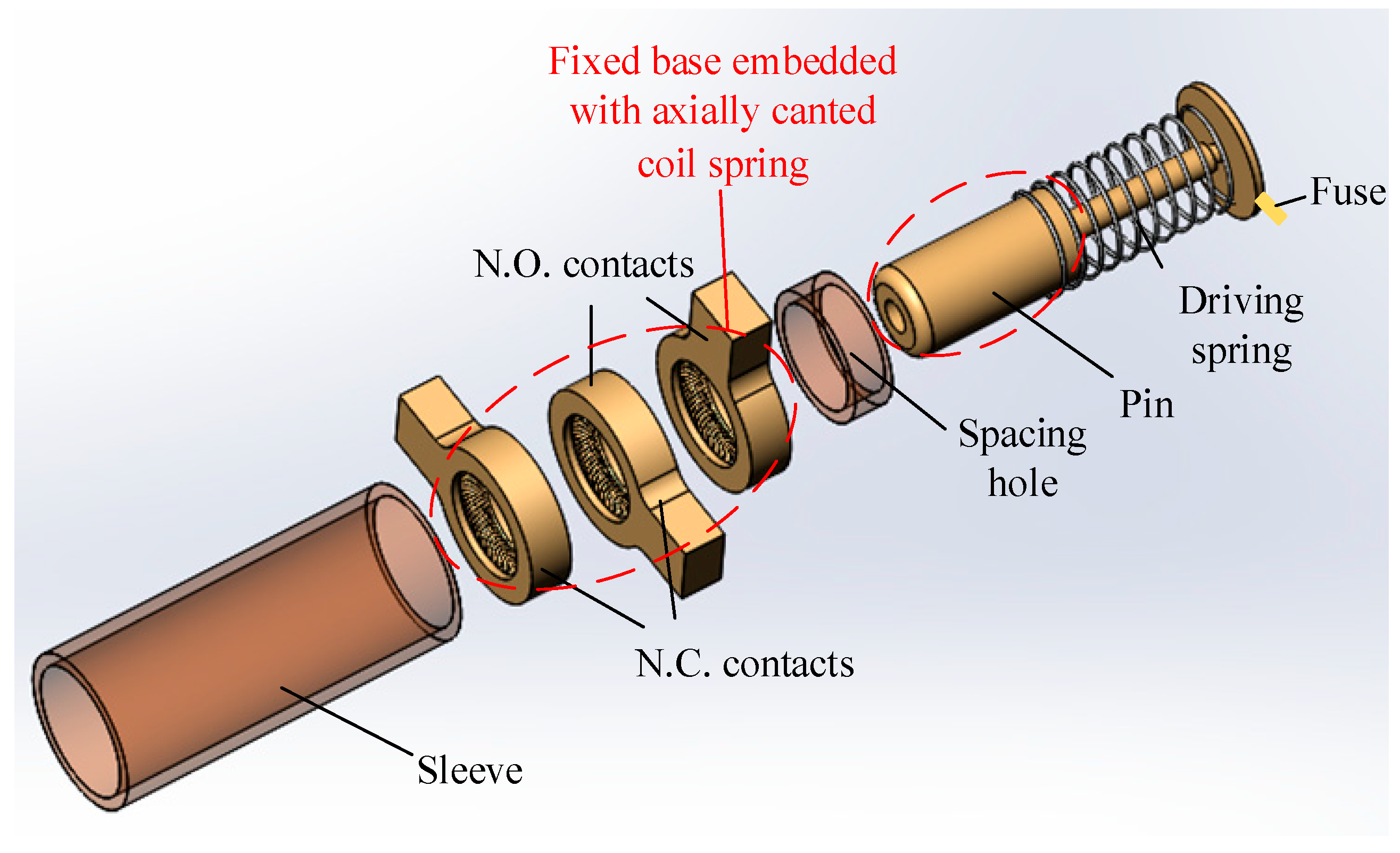
The designed axially canted coil spring structure, shown in Figure 2, is favored in high-power electrical interconnection engineering. The advantage of such a structure allows the small pin assemblies pass through high electrical power in a limited space. Meanwhile, the circuit resistance is required to be as small as possible in order to ensure a reduction in power consumption and a rise in temperature. However, the introduced axially canted coil spring within by-pass switches also brings up the current constriction problem in every mechanical detachable contact region. Although the classical Holm theory [9] stated that the increment of contact force could effectively reduce contact resistance, it would lead to higher insertion force and induce excessive mechanical sliding wear. So, the design of by-pass switches with axially canted coil springs to achieve the optimal mechanical and electrical performance has been of great interest among researchers and the industry.
Ever-present calculation models well describe the effects of interface profile [10,11,12,13], material properties [14,15,16], and contact force [17,18,19] on the contact resistance. But the relationship between contact area and contact force, and the relationship between insertion displacement and contact force, are two basic conditions for the electrical contact resistance calculation. To do this, Soler and Rangel [20] proposed a geometrical description of a canted coil spring as a particular type of space curve, and the influence of the canted angle on the geometrical curvature and torsion was investigated. Schriefer et al. [21] explicitly analyzed the effects of design parameters (wire diameter, canted angle, coil height, spring diameter, and number of turns) on the contact force and electrical resistance of axially canted coil springs in order to increase ampacity for high-current applications.
In recent years, a number of studies have advanced the understanding and application of canted coil springs. Some focused on experimental investigations of wear and leakage in spring-energized seals under high-cycle or extreme operating conditions, providing insights into the durability and tribological characteristics of canted coil spring energizers [22,23]. Others addressed material optimization and structural modeling, such as axisymmetric simulation approaches and material selection methods to improve sealing and electrical contact performance [24,25,26,27]. Numerical and finite element studies have also been conducted to investigate mechanical deformation, stress relaxation, and resilience of Ni-based alloy canted coil springs in dynamic seals [28], as well as to establish equivalent models for spring-energized rings to simplify computation [29]. In addition, several reviews on tribology and wear modeling highlighted the role of canted coil spring energizers in practical sealing and electrical contact applications, demonstrating their growing importance in multiphysics coupling analyses [30,31].
Nevertheless, due to the complexity and large number of optimization parameters of the axially canted coil springs, Guan et al. [32] simulated the mechanical contact deformation of the contact finger structure within GIS disconnector by introducing the equivalent elastic annular spring element. Nowadays, the commercial FE software codes provide the Contact Pair for structural contact and multiphysics contact modeling. However, when the simulation model contains too many Contact Pairs, a multi-fold increase in calculation convergence difficulty is observed. So, an analytical calculation model of mechanical force and electrical contact resistance is urgently demanded to substantially reduce the computational time for the optimization algorithm.
Therefore, this work aims to establish a comprehensive framework for analyzing the coupled mechanical–electrical behavior of by-pass switches with axially canted coil springs. The main tasks are as follows: (i) to develop an analytical model for insertion force and electrical contact resistance, (ii) to validate the model by finite element simulations, and (iii) to examine the influence of key structural parameters on the coupled performance. The purpose is to provide design-oriented formulas that reduce computational costs while retaining predictive accuracy. The structure of this paper is organized as follows: Section 2 describes the geometry of the by-pass switch with axially canted coil springs. Section 3 presents the mathematical model for insertion force and electrical contact resistance. Section 4 builds the simulation model using COMSOL Multiphysics for comparison. Section 5 investigates the effects of different spring configurations on insertion force and contact resistance and provides fitting formulas applicable to by-pass switches. Section 6 concludes the study.
Beyond the specific application in by-pass switches, the proposed modeling approach and the insights into the coupling between insertion force and electrical contact resistance are also applicable to other fields, such as electrical connectors, high-current relays, power electronic modules, and more generally, to the study of electrical contact phenomena in advanced energy systems.

2. Description of By-Pass Switches with Axially Canted Coil Spring

As shown in Figure 2, the mechanical structure of the by-pass switch mainly contains the cylindrical pin, axially canted coil springs, fixed bases, driving springs, and fuses. Figure 3a,b illustrate the fixed base embedded with an axially canted coil spring. The relevant parameters of the axially canted coil spring mainly include wire diameter ds, mean diameter of ring spring dm, the single coil size (long half-axis length al and short half-axis length as), and coil turn n. The single turn of the canted coil spring has one contact spot with the pin and two contact spots with the V-shape groove of the fixed base [shown in Figure 3c].
Initially, the driving spring is in a compressed state before fuse triggering [shown in Figure 4a]. The pin connects with the N.C., contacts L1 and L2, under the restriction of the spacing hole. When receiving a trigger command, the fuse burns out, and the pin pops up with the help of the driving spring. Then, the pin interconnects the three terminals of L1, L2, and L3 [shown in Figure 4b], and then disconnects with the terminal L2 [shown in Figure 4c].

3. Analytical Calculation of Insertion Force and Electrical Contact Resistance

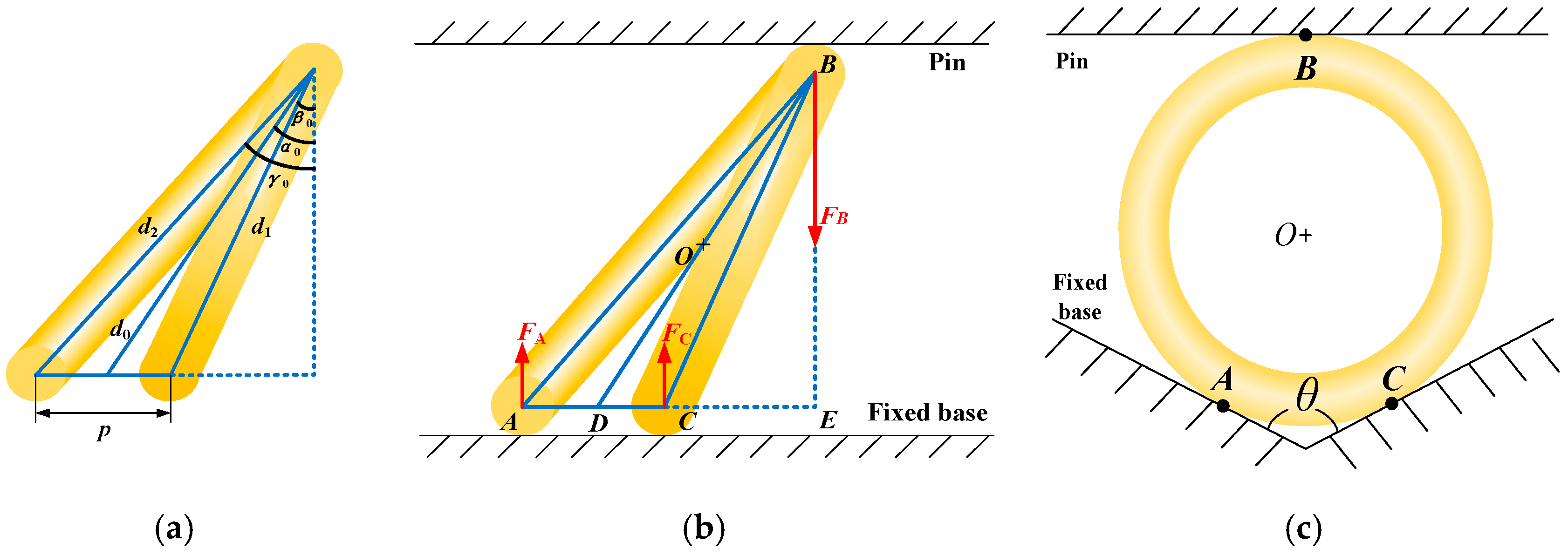
The axially canted coil spring wire model of interest and associated load conditions are given in relation to Figure 5. The centerline of a single coil spring wire could be mathematically described by a set of parametric equations:
x ( t ) = d 0 2 cos t y ( t ) = d 0 2 sin t cos α 0 z ( t ) = p t 2 π + d 0 2 sin t sin α 0
where t ϵ [0, π) for the first half turn of the coil spring, and t ϵ [π, 2π) corresponding to the second half turn of the coil spring; d0 and α0 are the diameter (center to center) and the axially canted angle of the reference circle; p is the pitch between two adjacent coil spring wires.
As shown in Figure 5b,c, Point O is taken as the reference circle center, and points A and C represent the mechanical contact boundaries between the single coil spring and the fixed base; point B is the mechanical contact position between the pin and the single coil spring. Then, the force balance equation in the vertical direction and the moment balance equation are as follows:
F B = F A + F C F A p + F B d 0 sin α 0 p 2 = 0
where FA and FC represent the loading forces provided by the fixed base, and FB is the loading force provided by the cylindrical pin.
Thus, the solutions of FA and FC are given as follows:
F A = 1 2 d 0 sin α 0 p F B F C = 1 2 + d 0 sin α 0 p F B
Furthermore, the initial forward tilt angle β0 of the first half-turn coil spring wire and the forward tilt angle γ0 of the second half-turn coil spring wire could be expressed as follows:
β 0 = arctan d 0 sin α 0 p 2 d 0 cos α 0 γ 0 = arctan d 0 sin α 0 + p 2 d 0 cos α 0
Then, the initial diameter of the reference circles for the first half-turn coil spring wire d1 is d 0 cos α 0 cos β 0 and the initial diameter of the reference circles for the second half-turn coil spring wire d2 is d 0 cos α 0 cos γ 0 . Figure 6a plots the initial contact between the pin and the single coil spring during the mechanical insertion process. So, the intersection angle φ0 between the line EF and the vertical axis line is expressed as follows:
φ 0 = arccos r pt ( r p r pc ) r pc
where rpt is the radial distance, and expressed as r pt = h ps d 0 cos α 0 sin α 0 r s ; rp is the cylindrical radius of the pin; rpc is the chamfer radius of the pin; hps is the center height of the pin; rs is the spring wire radius.
Given the insertion displacement x in the horizontal loading direction, the intersection angle is changed into the following:
φ = arcsin r pc sin φ 0 x r pc
and the radial distance rpt’ is written as follows:
r pt = r pt + Δ h
where Δh = rpccos φ’ − rpccos φ0 is the height variation in the single coil in the vertical direction.
Meanwhile, the change in the forward tilt angle β’ and γ’ could be expressed as follows:
β = arctan d 0 sin α p 2 d 0 cos α γ = arctan d 0 sin α + p 2 d 0 cos α
where the inclination angle α’ could be solved from (rpt’ + rs)sin α’ + d0cos α’ = hps. The diameter d1’ is revised as d 0 cos α cos β and d2’ is revised as d 0 cos α cos γ .
According to Mohr’s integral theorem [33], the deflection δ of the axially canted coil spring wire in the vertical direction under the load force is as follows:
δ = s F N ( x ) F N ( x ) ¯ E e A c d s + s T ( x ) T ( x ) ¯ G t I p d s + s M ( x ) M ( x ) ¯ E e I z d s
where F N x and F N x ¯ are the original load force and preload unit force, T x and T x ¯ are the original torque and preload unit torque, M x and M x ¯ are the original bending moment and preload unit bending moment, Ee is the elasticity modulus, Gt is the tangent modulus, Ac is the cross-sectional area of the single coil, Ip is the polar inertia moment, and Iz is the inertia moment, respectively.
Considering that the ratio of length and wire radius is larger than four for the single coil, the influences of shear and tensile force on the deformation of spring wire are ignored. The relationship between the deflection δ1 (δ2) of the first (second) half-turn coil spring wire and the vertical load force FB is listed in Appendix A. Then, the whole deflection δ of the single coil spring wire is as follows:
δ = δ 1 + δ 2 2
And then the stiffness ks of the single turn coil spring wire is as follows:
k s = F B δ
The equivalent stiffness kn of the whole axially canted coil spring wire with n turns in parallel is as follows:
k n = n k s = n F B δ
As shown in Figure 7, the friction force Ff between the pin and the axially canted coil spring is as follows:
F f = μ F con
in which μ is the friction coefficient.
The equations describing the force balanced relationship in vertical and horizontal direction are as follows:
F I = F I 1 + F I 2 = F con sin φ + F f cos φ F B = F con cos φ F f sin φ
So, the insertion force of the cylindrical pin is derived as follows:
F I = sin φ + μ cos φ cos φ μ sin φ F B
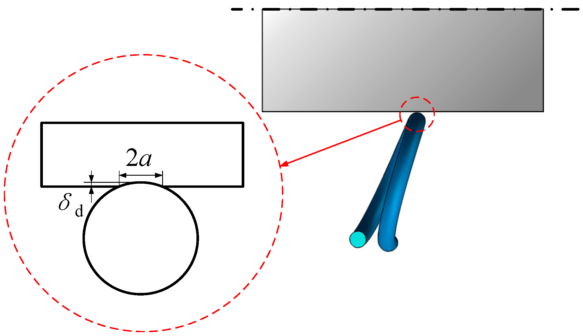
As illustrated in Figure 8, the mechanical contact between the single turn of axially canted coil spring wire and the cylindrical pin, and the mechanical contact between the spring wire and the fixed base, both could be equivalent to the classical Hertzian contact because of the substantial difference in radius of the two contacting members. In [34], the equation describing the relationship between the interference δd and the normal load force P is as follows:
P = 4 3 E * R e 1 2 δ d 3 2
where E* is the equivalent elastic modulus of two connected interface materials; Re is the equivalent curvature radius of the contact position.
The semi-major axis a and the semi-minor axis b of the produced elliptical contact area are as follows:
a = R e 1 δ d b = R e 2 δ d
where Re1 is the equivalent curvature radius, related to d0/2 and rp; Re2 is the equivalent curvature radius, related to rs and rp.
Then, the contact resistance Rc’ of the elliptical contact area is [9] as follows:
R c = ρ 2 π 0 d ξ a 2 + ξ 2 b 2 + ξ 2 1 / 2
where ρ is the electrical resistivity of the contact material.
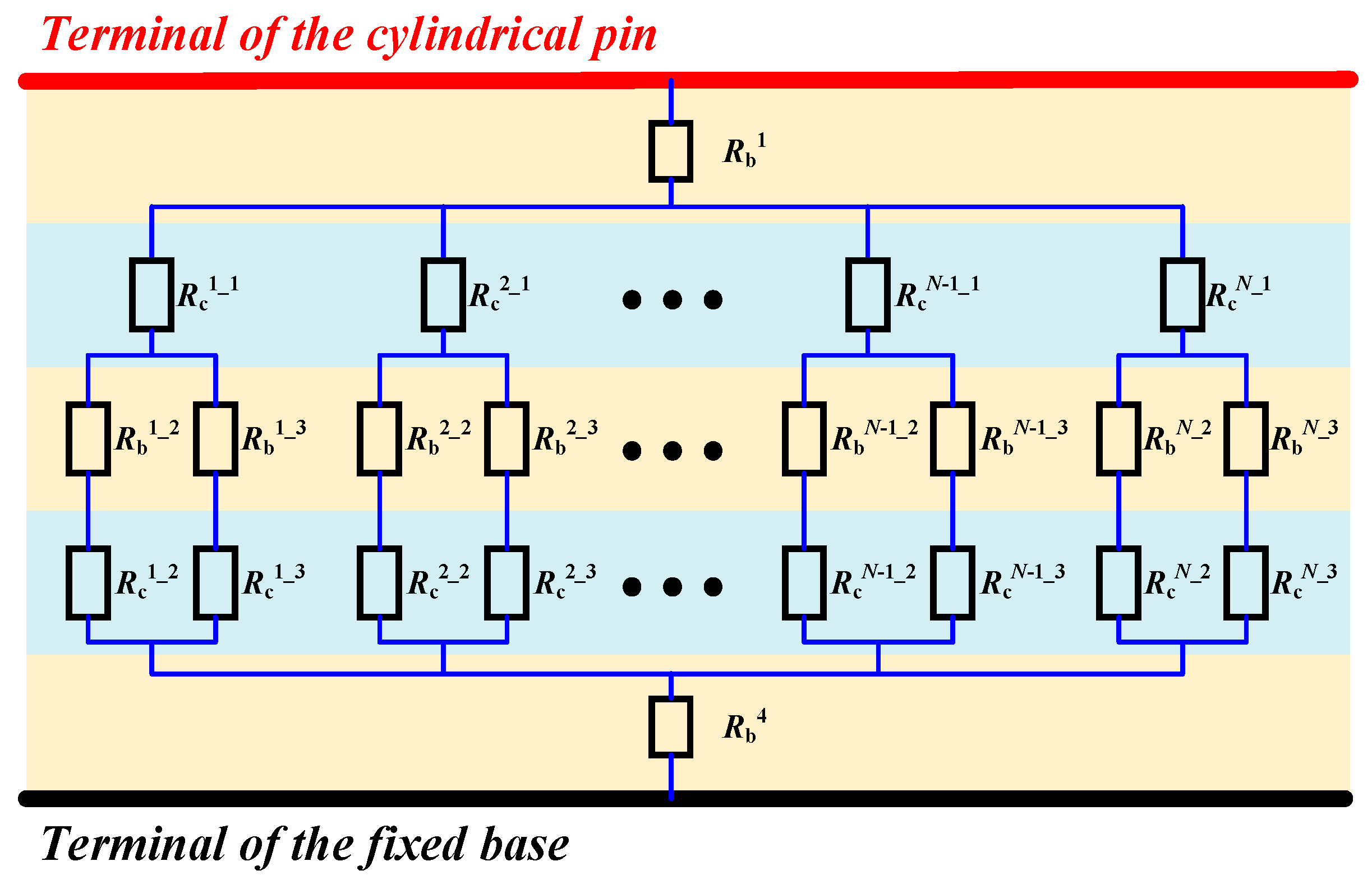
As shown in Figure 9, the contact resistance Rc″ produced by the cylindrical pin, the single-turn canted coil spring wire, and the fixed base is as follows:
R c = R c i _ 1 + R b i _ 2 + R c i _ 2 / / R b i _ 3 + R c i _ 3 = R c i _ 1 + R b i _ 2 + R c i _ 2 R b i _ 3 + R c i _ 3 R b i _ 2 + R c i _ 2 + R b i _ 3 + R c i _ 3
where i represents the ith single-turn canted coil spring and R c i _ 1 is the contact resistance between the cylindrical pin and the single-turn canted coil spring wire. R b i _ 2 and R b i _ 3 are the bulk resistance of the axially canted coil spring wire. Both R c i _ 2 and R c i _ 3 are the paralleled contact resistance between the single-turn canted coil spring wire and the fixed base.
The total resistance Rc of by-pass switch could be considered as the sum of the bulk resistance R b 1 of the cylindrical pin, the bulk resistance R b 4 of the fixed base and the parallel resistance of Rc″, and could be written into the following:
R c = R b 1 + R b 4 + R c / N

4. FEM Modeling for Mechanical and Electrical Field Analysis

To further determine the contact stress distribution and electrical current distribution of the by-pass switch with axially canted coil spring, the commercial FEM software COMSOL Multiphysics is used to numerically simulate the mechanical contact and electrical field. COMSOL Multiphysics® 6.3 (COMSOL AB, Stockholm, Sweden) provides a more flexible multiphysics coupling environment. It allows seamless integration of electrical, thermal, and mechanical fields, which is particularly advantageous for accurately simulating the electro–thermal–mechanical interactions in this work. As shown in Figure 10, a hollow cylinder with a radius of 5.45 mm and a chamfer radius of 1.5 mm is modeled as the pin, and a concentric cylinder with a radius of 9.5 mm and a V-shape groove is built as the fixed base. The main size parameters of the by-pass switch are listed in Table 1, and the material properties are listed in Table 2.
A Cartesian space curve is created by multiplying the helix curve of the linear coil by a rotation matrix and is located between the pin and the fixed base. Two groups of contact pairs are set for the whole mechanical structure during the insertion process individually. The first group is used to characterize the mechanical contact between the pin and the axially canted coil spring, and the second group is to describe the mechanical contact between the axially canted coil spring and the fixed base. For mechanical contact problem simulation, the axially canted coil spring outer surface is set as the target boundary, and the pin outer surface and the V-shape groove surface are appointed as the source boundary. Meanwhile, the outer surface of the fixed base is fixed, and the displacement load is vertically applied to the top surface of the cylindrical pin using a single step of 0.001 mm, together with the total 500 sub-steps. A constant electrical potential of 10mV is loaded on the terminal of the pin, and the fixed base terminal is grounded electrically. The whole geometry model is meshed with 3D traditional tetrahedral elements, and the meshes are graded outward from the initial contact point, with the densest mesh in the contact regions. The minimum size of the mesh is 50 μm and the contact surfaces are assumed to be smooth.
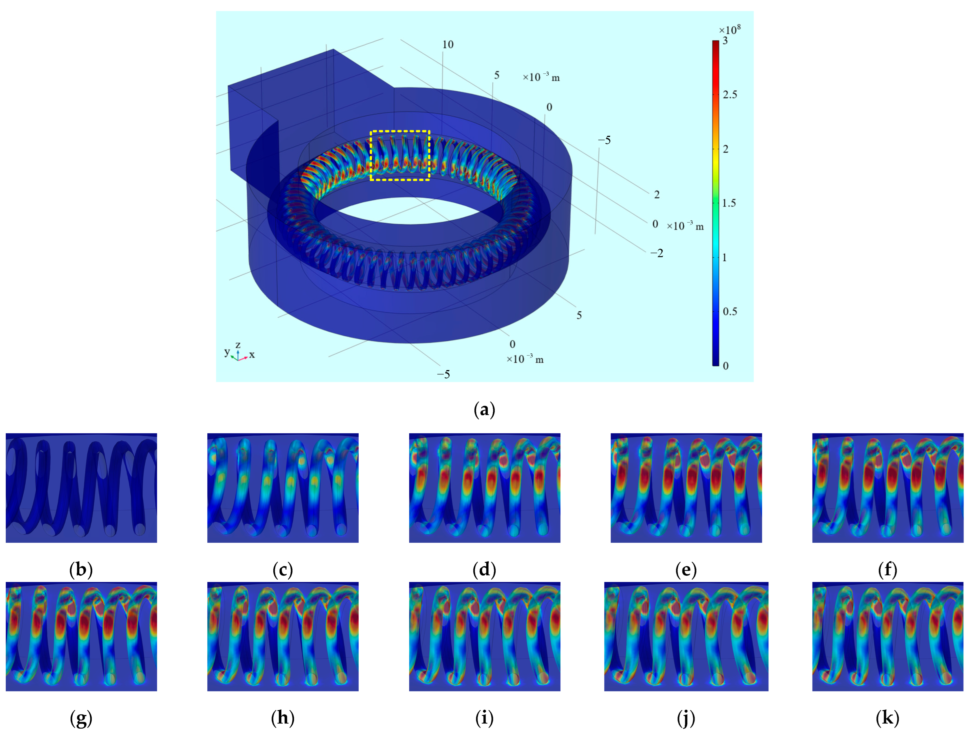
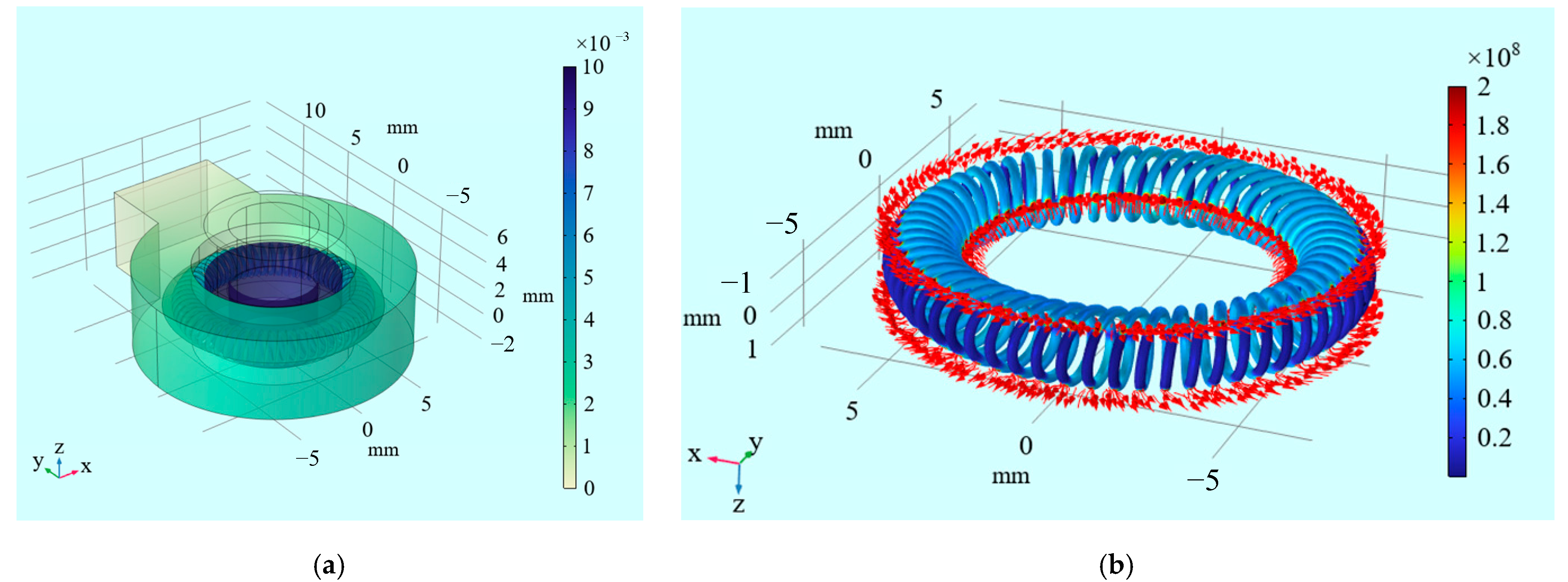
The stress distribution simulation results of the axially canted coil spring at 0.5 mm insertion displacement load are shown in Figure 11. As plotted, the stress becomes higher toward the contact region between the pin and the axially canted coil spring wires, between the axially canted coil spring wires and the V-shape groove. The observed maximum contact stress of the axially canted coil spring is 252.5 MPa, almost a quarter of the yield strength of 1000 MPa of the involved material CuBe2. The results indicate that the deformation of the axially canted coil spring is elastic. In addition, it is noted that the deflection deformation of the axially canted coil spring exists simultaneously in the radial and circumferential direction during the whole insertion process. Variations in the contact profile of individual spring wire indicate that when the insertion displacement increases from 0.05 mm (initial contact) to 0.1 mm, the deformation in the radial direction enlarges the same as in the circumferential direction. However, the contact zone mainly expands along the circumferential direction with further increment of insertion displacement. As seen, the reference circle of the axially canted coil spring shows substantial deflection with the increment of insertion displacement. This results in the non-negligible position shift in every turn of the coil spring, which agrees well with the assumption in the theoretical modeling process. Once the pin chamfer part is inserted completely, the mechanical stress results remain stable. Figure 12 plots the electrical current lines profile and isopotential maps at 10mV electrical potential load. The current flows from the pin terminal to the fixed base terminal, and the current lines constrict uniformly toward every contact region within the axially canted springs and the simulated stable contact resistance is 1.85 μΩ.

5. Results and Discussion

5.1. Validity of Analytical Model

Figure 13a shows the variations in the mechanical insertion force of the cylindrical pin and an axially canted coil spring as a function of insertion displacement. The mechanical insertion force behavior appears to be characterized by a few distinct stages. In the first stage, the insertion force increases nonlinearly to 14.85 N, followed by a gradual decrease in contact resistance from 10.29 mΩ to 1.87 mΩ. At 0.259 mm, the maximum value of 14.85 N is named as the insertion force peak value. After 0.412 mm, the insertion force remains stable at about 11.99 N. When the insertion displacement is less than 0.412 mm, the spring coils are in contact with the pin chamfer, resulting in a nonlinear variation in the insertion force. After the displacement reaches 0.412 mm, the pin is fully inserted, and the spring coils maintain stable contact with the cylindrical surface, leading to a steady insertion force. The relationship between the insertion force and pin displacement correlates well with that of the electrical connectors [35,36,37]. As shown in Figure 13b and Figure 13c, when the insertion displacement is less than 0.257 mm, the contact force and contact area increase rapidly to 41.44 N and 2.21 mm2, respectively. Afterwards, they gradually increase to 46.06 N and 2.42 mm2. Once the displacement exceeds this threshold, the contact force of 46.06 N, contact area of 2.42 mm2, and contact resistance of 1.79 μΩ remain stable. The coefficient of friction between the spring and the cylindrical pin was determined as μ = 0.26.
The simulation results are also included in Figure 13. The FE numerical calculation results are in excellent agreement with the analytical calculations for the coil turns n ranging from 35 to 65. The maximum deviation of these two critical characterization parameters for the canted coil spring is less than 0.7%. This means the equivalent Hertz contact between the single canted coil spring and the cylindrical pin is reasonable. The above comparisons for the typical characteristic parameters demonstrate the feasibility of the proposed direct analytical stiffness modeling method. In terms of computational time, there is a substantial difference between the FE simulation and the analytical calculation model. FE simulation requires 11.5 days for the convergence of mechanical contact and electrical analysis. However, for the analytical calculation model, the exact solution is obtained in 19 s, which is more than 50,000 times faster faster than the FE simulation in terms of computation time. Both calculations ran on a specialized simulation workstation with an Intel Xeon Silver 4210R processor, with 64 GB of RAM and 2.4 GHz max clocking speed.
The above results demonstrate that the elasticity of the axially canted coil spring structure is nonlinear in the insertion process. The variations in contact area and contact resistance as a function of the contact force are mathematically fitted. The fitting power laws Sc = 0.17Fcon0.7 and Rc = 6.53Fcon−0.34 indicate that the contact area and contact resistance of the by-pass switch with axially canted coil springs could be predicted according to the contact force in the mechanical insertion process.

5.2. Influencing Factors

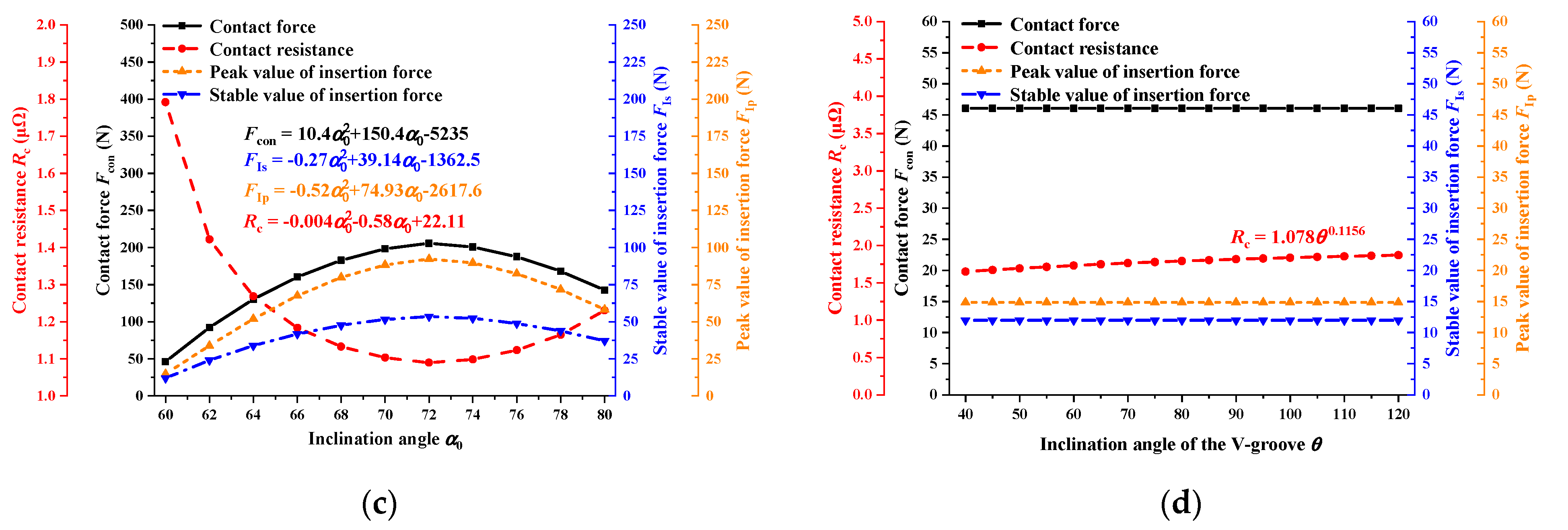
Figure 14 shows the effects of wire diameter ds of the axially canted coil springs, chamfer radius of the pin rpc of the cylindrical pin, inclination angle α0 of the single coil, and the V-shape groove angle θ of the fixed base on the mechanical insertion and electrical contact behaviors. It is obvious that the relationship between insertion force and insertion displacement has similar changing trends, and the contact resistance always decreases nonlinearly and monotonically with the cylindrical pin moving forward. As shown in Figure 14a, the maximum value of 0.201 N and 98.068 N, and the stable value of 0.156 N and 82.732 N for the insertion force both increases, and the stable value of 8.268 μΩ and 0.901 μΩ for the contact resistance decreases with the wire diameter of axially canted coil springs increasing from 0.1 mm to 0.5 mm. When the chamfer radius of the pin increases from 1 mm to 2 mm, the maximum insertion force reduces from 15.942 N to 14.262 N and the stable contact resistance decreases from 12.022 N to 11.991 N correspondingly [shown in Figure 14b]. This indicates that the increment of chamfer radius of the pin could decrease the peak value of insertion force and stable value of contact resistance. With the angle expanding from 40° to 120°, the insertion force curves coincide, and the contact resistance increases from 1.649 μΩ to 1.871 μΩ [shown in Figure 14d].
In order to further establish the relationship between the characteristic parameters (contact force Fcon between pin and axially canted coil spring, the insertion force peak value FIp and stable value FIs, the contact resistance stable value Rc) and size parameters (wire diameter ds, chamfer radius of the pin rpc, inclination angle α0 of the reference circle, V-type groove angle θ), more theoretical calculation results are obtained by taking size parameters in Table 1 as the central values (shown in Figure 15). The power function and second-order polynomial function are selected to guarantee the coefficient of determination R2 value larger than 0.95, and the fitting results of the characteristic parameters and size parameters are presented in Table 3. It is clear that the V-type groove angle only affects the contact resistance, while the wire diameter and the inclination angle of the reference circle have significant effects on all four characteristic parameters. The effect of wire diameter is relatively straightforward. As the wire diameter increases, the cross-sectional area of a single coil (Ac), the polar moment of inertia (Ip), and the moment of inertia (Iz) all increase. This reduces coil deformation and increases stiffness, thereby raising the contact force. Consequently, both the peak and stable insertion forces increase, and the contact area also expands, which leads to a decrease in contact resistance. The influence of inclination angle is more complex because it simultaneously affects multiple variables related to contact force. As shown in Figure 15, the contact force increases initially and then decreases with the inclination angle. This trend results in both the peak and stable insertion forces first increasing and then decreasing. The contact area follows the same variation as the contact force, which in turn causes the contact resistance to first decrease and then increase. Taking the contact resistance as an example, the advantage of establishing the above formulas is to obtain a related expression Rc = k1ds−1.37rpc−0.048α0−2.511θ0.1156 + b1, for the inclination angle of reference circle ranging from 60° to 72°, including two undetermined coefficients k1 and b1. Then, k1 and b1 could be determined by two known values of contact resistance, which could be obtained by the finite element simulation or experimental measurement. Other investigations into contact resistance could be conducted by changing the size parameters. This method could also be applied to study other characteristic parameters. The presented method proves to be highly effective compared with the time-consuming FE simulation.

6. Conclusions

This work aims to propose a comprehensive framework for analyzing the coupled mechanical–electrical behavior of by-pass switches with axially canted coil springs. The novelty and task of this study lie in establishing a coupled mechanical–electrical analytical framework that achieves results comparable to FE simulations with much higher efficiency and further provides associated empirical formulas. The novelty and task of this study lie in establishing a coupled mechanical–electrical analytical framework that achieves results comparable to FE simulations with much higher efficiency and further provides associated empirical formulas. Our results indicated that the relationship between the constriction resistance and contact force conforms to a power function well. Thinner wire diameter and larger inclination angle of the reference circle for the axially canted coil spring could decrease the insertion force, while a larger V-type groove angle could reduce the total contact resistance with the insertion force remaining constant. And larger chamfer radius could smooth the insertion process with a lower maximum value and the same stable value of the insertion force. A series of empirical formulas and associated applicable methods are presented to guide the axially canted coil spring design. The FE simulation requires 11.5 days for convergence, whereas the analytical calculation model achieves the solution in 19 s, which is more than 50,000 times faster while providing similar results. The main advantages of the proposed approach are computational efficiency and clear physical interpretability, while simplifications of nonlinear effects and material imperfections may limit accuracy under extreme conditions. Future work will focus on experimental validation of the proposed model to verify its accuracy.

Author Contributions

Conceptualization, W.R. and C.Z.; methodology, C.Z.; software, C.Z.; validation, C.Z., M.L. and J.L.; formal analysis, C.Z.; investigation, M.L.; resources, W.R.; data curation, J.L.; writing—original draft preparation, C.Z.; writing—review and editing, W.R.; visualization, M.L.; supervision, J.L.; project administration, W.R.; funding acquisition, W.R. All authors have read and agreed to the published version of the manuscript.

Funding

This work was supported in part by the National Natural Science Foundation of China (Grant numbers 52377140 and 52407166), in part by the Aeronautical Science Foundation of China (Grant number ASFC-20240002077001), in part by the Postdoctoral Science Foundation of China (Grant number 2023M730849), and in part by the Postdoctoral Science Foundation of Heilongjiang (Grant number LBH-Z22189).

Data Availability Statement

Data are contained within the article.

Conflicts of Interest

Ming Li was employed by China Aero-Polytechnology Establishment. Other authors declare no conflict of interest.

Appendix A

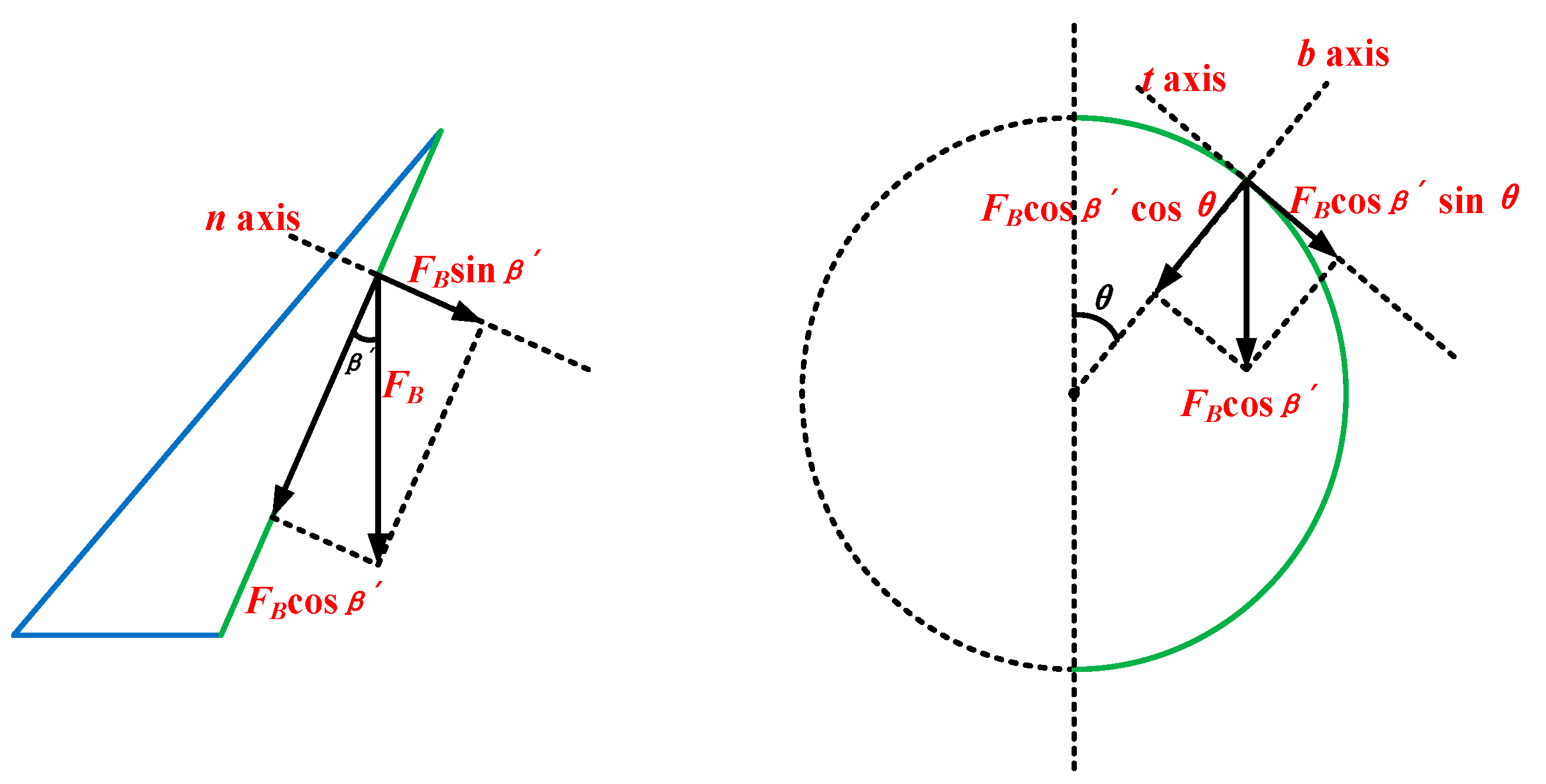
The micro segments ds1 and ds2 for the first- and second-half coil, respectively, are further selected to analyze the deformation state. According to the principle of force balance, the load force FB, which originally applies to point B, could be translated to the micro segment ds1, and the additional couple moments M1 could be expressed by the following:
M 1 = F d 1 2 d 1 2 cos θ sin β
The tensile force Ft1 along the t-axis for the micro segment ds1 is as follows:
F t 1 = F cos β sin θ
And the shear force Fb1 and Fn1 along the b-axis and n-axis, respectively, are as follows:
F b 1 = F cos β cos θ
F n 1 = F sin β
For the moment analysis, the rotation torque Tt1 along the t-axis is as follows:
T t 1 = M cos β sin θ
The bending moment of Mb1 and Mn1 along the b-axis and n-axis are as follows:
M b 1 = M cos β cos θ
M n 1 = M sin β
Figure A1. Analysis for the first turn of the single coil.
Machines 13 00878 g0a1
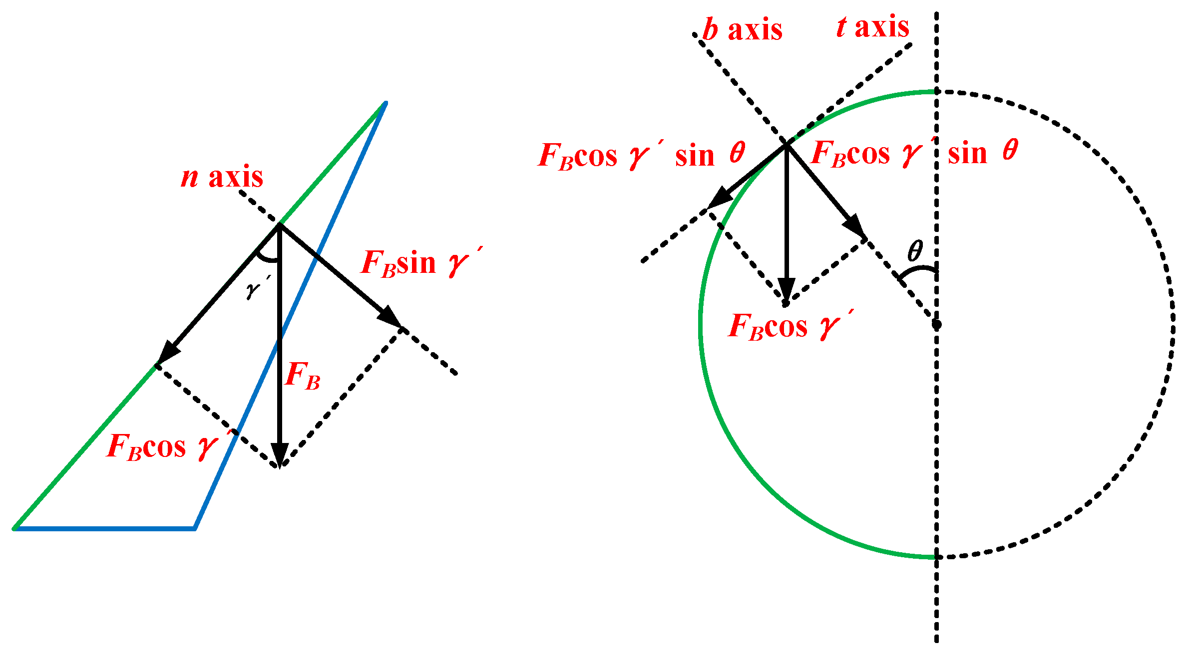
The load force FB, which originally applies to point B, could also be taken to the micro segment ds2 in the second half coil, and the additional couple moments M2 could be obtained by the following:
M 2 = F d 2 2 d 2 2 cos θ sin γ
The tensile force Ft2 along the t-axis for the micro segment ds2 is as follows:
F t 2 = F cos γ sin θ
And the shear force Fb2 and Fn2 along the b-axis and n-axis, respectively, are as follows:
F b 2 = F cos γ cos θ
F n 2 = F sin γ
For the moment analysis, the rotation torque Tt2 along the t-axis is as follows:
T t 2 = M cos γ sin θ
The bending moment Mb2 and Mn2 along the b-axis and n-axis are as follows:
M b 2 = M cos γ cos θ
M n 2 = M sin γ
Figure A2. Analysis for the second turn of the single coil.
Machines 13 00878 g0a2

References

  1. Kabir, M.N.; Mishra, Y.; Ledwich, G.; Dong, Z.Y.; Wong, K.P. Coordinated Control of Grid-Connected Photovoltaic Reactive Power and Battery Energy Storage Systems to Improve the Voltage Profile of a Residential Distribution Feeder. IEEE Trans. Ind. Inform. 2014, 10, 967–977. [Google Scholar] [CrossRef]
  2. Strasser, T.; Andren, F.; Kathan, J.; Kathan, J.; Cecati, C.; Buccella, C.; Siano, P.; Leitao, P.; Zhabelova, G.; Vyatkin, V.; et al. A Review of Architectures and Concepts for Intelligence in Future Electric Energy Systems. IEEE Trans. Ind. Electron. 2015, 62, 2424–2438. [Google Scholar] [CrossRef]
  3. Zubi, G.; Dufo-Lopez, R.; Carvalho, M.; Pasaoglu, G. The lithium-ion battery: State of the art and future perspectives. Renew. Sustain. Energy Rev. 2018, 89, 292–308. [Google Scholar] [CrossRef]
  4. Rudoy, E.; Semerie, J.P.; Pasquier, E.; Dohan, Y. High capacity battery cell by-pass switches surge/short-circuit current testing results. In Proceedings of the 6th European Space Power Conference (ESPC), Porto, Portugal, 6–10 May 2002; pp. 561–564. [Google Scholar]
  5. Novak, B.; Szabo, L. Temperature Rise of Canted Spring Contacts During Fault Current. In Proceedings of the 63rd IEEE Holm Conference on Electrical Contacts, Denver, CO, USA, 10–13 September 2017. [Google Scholar]
  6. Hannan, M.A.; Hoque, M.M.; Mohamed, A.; Ayob, A. Review of energy storage systems for electric vehicle applications: Issues and challenges. Renew. Sustain. Energy Rev. 2017, 69, 771–789. [Google Scholar] [CrossRef]
  7. Emadi, A.; Rajashekara, K.; Williamson, S.S.; Lukic, S.M. Topological overview of hybrid electric and fuel cell vehicular power system architectures and configurations. IEEE Trans. Veh. Technol. 2005, 54, 763–770. [Google Scholar] [CrossRef]
  8. Shi, Z.Q.; Li, S.; Wang, Q.S.; Gao, Z.P.; Jia, S.L.; Wang, L.J. Numerical investigation on the steady temperature rise of a by-pass switch. Fusion Eng. Des. 2017, 124, 54–58. [Google Scholar] [CrossRef]
  9. Holm, R. Electric Contacts: Theory and Application; Springer: New York, NY, USA, 1967; pp. 14–16. [Google Scholar]
  10. Greenwood, J.A.; Williamson, J.B.P. Contact of nominally flat surfaces. Proc. R. Soc. Lond. A 1966, 295, 300–319. [Google Scholar]
  11. Blanc, J.; Grime, D.; Blateyron, F. Surface characterization based upon significant topographic features. In Proceedings of the 13th International Conference on Metrology and Properties of Engineering Surfaces, Twickenham, UK, 12–15 April 2011. [Google Scholar]
  12. Ning, Y.; Polycarpou, A.A. Extracting summit roughness parameters from random Gaussian surfaces accounting for asymmetry of the summit heights. J. Tribol.-Trans. ASME. 2004, 126, 761–766. [Google Scholar]
  13. Liu, H.; McBride, J.W. A Finite-Element-Based Contact Resistance Model for Rough surfaces: Applied to a Bilayered Au/MWCNT Composite. IEEE Trans. Compon. Pack. Manuf. Technol. 2018, 8, 919–926. [Google Scholar] [CrossRef]
  14. Johnson, K.L. Contact Mechanics; Cambridge University Press: New York, NY, USA, 1985; pp. 109–112. [Google Scholar]
  15. Sano, Y. Effect of space angle on constriction resistance and contact resistance for the case of line contact. IEEE Trans. Compon. Hybrids Manuf. Technol. 1985, 8, 228–234. [Google Scholar] [CrossRef]
  16. Sharma, A.; Jackson, R.L. A Finite Element Study of an Elasto-Plastic Disk or Cylindrical Contact Against a Rigid Flat in Plane Stress with Bilinear Hardening. Tribol. Lett. 2017, 65, 112. [Google Scholar] [CrossRef]
  17. Kogut, L.; Komvopoulos, K. Electrical contact resistance theory for conductive rough surfaces. J. Appl. Phys. 2003, 94, 3153–3162. [Google Scholar] [CrossRef]
  18. Kogut, L.; Komvopoulos, K. Electrical contact resistance theory for conductive rough surfaces separated by a thin insulating film. J. Appl. Phys. 2004, 95, 576–585. [Google Scholar] [CrossRef]
  19. Riba, J.R.; Mancini, A.G.; Abomailek, C.; Capelli, F. A 3D-FEM-Based Model to Predict the Electrical Constriction Resistance of Compressed Contacts. Measurement 2018, 114, 44–50. [Google Scholar] [CrossRef]
  20. Soler, J.M.; Rangel, R.H. Geometrical characterization of canted coil springs. Proc. Inst. Mech. Eng. C J. Eng. Mech. Eng. Sci. 2006, 220, 1831–1841. [Google Scholar] [CrossRef]
  21. Schriefer, T.; Hofmann, M.; Rauh, H.; Eckardt, B.; Maerz, M. Parameter Study on the Electrical Contact Resistance of Axially Canted Coil Springs for High-current Systems. In Proceedings of the 29th International Conference on Electrical Contacts (ICEC)/64th IEEE Holm Conference on Electrical Contacts, Albuquerque, NM, USA, 14–18 October 2018. [Google Scholar]
  22. Huang, L. Wear and leakage assessments of canted coil spring-energized polytetrafluoroethylene seals under ultra-high cycle operations. Wear 2022, 488–489, 204122. [Google Scholar] [CrossRef]
  23. Liu, D.; Zhao, J.; Li, S.; Zhao, X.; Huang, L. Experimental study on tribological and leakage characteristics of a rotating spring-energized seal under high and low temperature. Machines 2023, 11, 221. [Google Scholar] [CrossRef]
  24. Zhao, X.; Li, S.; Liu, D.; Huang, L. Material optimization method for a spring-energized seal based on wear analysis. Lubricants 2024, 12, 288. [Google Scholar] [CrossRef]
  25. Zhang, F.; Xiang, C.; Guo, F.; Jia, X. An equivalent axisymmetric modeling approach for circumferential springs under large deformation based on mechanical anisotropy. Proc. Inst. Mech. Eng. C J. Mech. Eng. Sci. 2024, 238, 8376–8389. [Google Scholar] [CrossRef]
  26. Zhang, W.; Schriefer, J.; Liu, J.; Sun, Y.; Zhu, J.; Song, J. Effects of design parameters on the contact force and electrical resistance of axially canted coil springs. J. Mech. Sci. Technol. 2023, 37, 1234–1242. [Google Scholar]
  27. Chen, S.; Yang, X.; Guo, F.; Zhang, B.; Wang, W.; Wang, Y. Sealing Performance Evaluation and Structural Optimization for Reducing Leakage Failures of Lip Seal Considering High-Speed Rotation Frictional Heat. Tribol. Trans. 2024, 67, 962–979. [Google Scholar] [CrossRef]
  28. Yu, Y.; Zhang, W.; Sun, Y.; Cong, M.; Zhu, J.; Song, J. Simulation analysis of deformation behavior and resilience of Ni-based alloy canted coil spring for dynamic seal. Acta Aeronaut. Astronaut. Sin. 2022, 43, 425527. [Google Scholar]
  29. Liu, J.; Zhang, W.; Sun, Y.; Cong, M.; Zhu, J.; Song, J. Research on design optimization and simulation analysis of deformation behavior of Ni-based alloy canted coil spring for dynamic seal. J. Appl. Mech. Mater. 2025, 24, 486. [Google Scholar]
  30. Amenta, F.; Ceretti, E.; Rizzuti, S.; Umbrello, D.; Micari, F. Tribological behaviour of PTFE composites for spring-energized seals under rotary conditions. Wear 2022, 482–483, 203989. [Google Scholar]
  31. Yan, L.; Guan, L.; Wang, D.; Xiang, D. Application and prospect of wear simulation based on ABAQUS: A review. Lubricants 2024, 12, 57. [Google Scholar] [CrossRef]
  32. Guan, X.Y.; Wu, L.; Shu, N.Q.; Peng, H.; Li, Q.Q.; Shen, Q.Y. Finite Element Analysis on Forces, Currents, and Magnetic Fluxes of Misaligned GIS Disconnector. IEEE Trans. Power Deliv. 2018, 33, 2484–2491. [Google Scholar] [CrossRef]
  33. Popov, E.P. Mechanics of Materials, 2nd ed.; Prentice-Hall Inc.: Saddle River, NJ, USA, 1976. [Google Scholar]
  34. Hertz, H. Über Die Berührung Fester Elastischer Körper. J. Reine Angew. Math. 1882, 92, 156. [Google Scholar] [CrossRef]
  35. Qin, B.; Zhang, Y. Comprehensive analysis of electro-mechanical characteristics and new regression models of a novel slanted groove electrical connector. Int. J. Non-Linear Mech. 2024, 166, 104863. [Google Scholar] [CrossRef]
  36. Meng, Y.; Ren, W.B.; Zhang, C. Investigation on Intermittent Failure Phenomenon of Electrical Connectors Under Repetitive Mechanical Insertion and Withdrawal Operations. IEEE Trans. Compon. Pack. Manuf. Technol. 2022, 12, 1533–1541. [Google Scholar] [CrossRef]
  37. Wu, B.H.; Lee, C.Y.; Chiang, Y.C.; Cao, S.Z.; Cao, X.; Zhang, G.D.; Zhou, S.P.; Wang, B.Q. Study on the contact performance of electronic EON connectors under axial vibration. IEEE Trans. Compon. Pack. Manuf. Technol. 2018, 8, 2090–2097. [Google Scholar] [CrossRef]
Figure 1. Working principle of by-pass switches. (a) Original position. (b) Triggering state. (c) After triggering.
Machines 13 00878 g001
Figure 2. Mechanical structure of the whole by-pass switch.
Machines 13 00878 g002
Figure 3. Illustrations of axially canted coil spring and mating status. (a) Axially canted coil spring. (b) Mating status. (c) Contact spots of the single turn spring wire.
Machines 13 00878 g003
Figure 4. Mechanical working state of the by-pass switch. (a) Original position. (b) Triggering state. (c) After triggering.
Machines 13 00878 g004
Figure 5. Description of a single axially canted coil spring wire and associated contact problem. (a) Defined variables. (b) Loading forces. (c) V-shape structure of the fixed base.
Machines 13 00878 g005
Figure 6. Schematic plot of the mechanical insertion process. (a) Initial contact. (b) Elastic deformation. (c) Variations in contact position on the cylindrical pin.
Machines 13 00878 g006
Figure 7. Illustration of the contact load force.
Machines 13 00878 g007
Figure 8. Schematic of the single canted coil spring wire and the pin.
Machines 13 00878 g008
Figure 9. Illustration of contact resistance of the by-pass switch with axially canted coil springs.
Machines 13 00878 g009
Figure 10. Illustration of simulation model. (a) Geometry model. (b) Boundary conditions. (c) FEM mesh.
Machines 13 00878 g010
Figure 11. Variations in contact stress distribution as a function of insertion displacement. (a) Insertion displacement of 0.6 mm. (b) Zoomed-in view of 0.05 mm. (c) Zoomed-in view of 0.08 mm. (d) Zoomed-in view of 0.1 mm. (e) Zoomed-in view of 0.15 mm. (f) Zoomed-in view of 0.2 mm. (g) Zoomed-in view of 0.25 mm. (h) Zoomed-in view of 0.3 mm. (i) Zoomed-in view of 0.4 mm. (j) Zoomed-in view of 0.45 mm. (k) Zoomed-in view of 0.5 mm.
Machines 13 00878 g011
Figure 12. Simulation results for 10 mV electrical potential load. (a) Distributions of electrical potential. (b) Distributions of the current density modulus and electrical current lines profile.
Machines 13 00878 g012
Figure 13. Comparison of the analytical results and FE simulation results for (a) insertion force; and (b) contact force. (c) Fitting results of the contact area and contact resistance.
Machines 13 00878 g013
Figure 14. Variations in the insertion force and contact resistance as a function of the insertion displacement. (a) The wire diameter ds = 0.1, 0.3, and 0.5 mm. (b) The chamfer radius of the pin rpc = 1.0, 1.5, and 2.0 mm. (c) The inclination angle of the single coil spring α0 = 60°, 70°, and 80°. (d) The inclination angle of the V-shape groove θ = 40°, 80°, and 120°. (Solid lines represent the insertion force, while dashed lines represent the contact resistance).
Machines 13 00878 g014
Figure 15. Variations in contact force Fcon, contact resistance Rc, stable value FIs, and peak value FIp of the insertion force as functions of (a) wire diameter ds, (b) pin corner radius rpc, (c) inclination angle α0; and (d) V-shape groove angle θ.
Machines 13 00878 g015aMachines 13 00878 g015b
Table 1. Main size parameters.
ComponentsParametersValue
Axially canted coil springDiameter d02.15 [mm]
Inclination angle α060°
Wire diameter ds0.3 [mm]
Turn n65
Pitch p0.35 [mm]
Cylindrical pinCenter height hps7.0 [mm]
Cylinder radius rp5.45 [mm]
Chamfer radius rpc1.5 [mm]
Fixed baseV-shape groove angle θ80°
Table 2. Properties of involved materials.
ComponentsMaterialYoung’s Modulus (GPa)Tangent Modulus (GPa)Density
(kg/m3)
Poisson’s RatioElectrical Resistivity (Ω·m)
Canted coil springBeryllium bronze (CuBe2)1285082500.39.5 × 10−8
Cylindrical pinRed copper1164689400.331.68 × 10−8
Fixed base
Table 3. The fitting results of the characteristic parameters and size parameters.
ParametersWire Diameter ds Chamfer Radius rpcInclination Angle of
Reference Circle α0
V-Shape Groove Angle θ
Contact force Fcon4661.2 × ds3.86710.4α02 + 150.4α0 − 5235
Peak value of
insertion force FIp
1214.8 × ds3.868−0.27α02 + 39.14α0 − 1362.5
Stable value of
insertion force FIs
1382.1 × ds3.80715.885 × rpc−0.162−0.52α02 + 74.93α0 − 2617.6
Contact resistance Rc0.348 × ds−1.371.828 × rpc−0.048−0.004α02 − 0.58α0 + 22.11
(46,720α0−2.511, 60° ≤ α0 ≤ 72°;
0.0082α0−2.511, 72° < α0 ≤ 80)
1.078 × θ0.1156
Disclaimer/Publisher’s Note: The statements, opinions and data contained in all publications are solely those of the individual author(s) and contributor(s) and not of MDPI and/or the editor(s). MDPI and/or the editor(s) disclaim responsibility for any injury to people or property resulting from any ideas, methods, instructions or products referred to in the content.