Article

A Multi-Layer Triboelectric Material Deep Groove Ball Bearing Triboelectric Nanogenerator: Speed and Skidding Monitoring

1
School of Smart Logistics and Manufacturing, Wuhu Vocational Technical University, Wuhu 241003, China
2
Jiangsu Provincial Key Laboratory of Special Robot Technology, Hohai University, Changzhou Campus, Changzhou 213022, China
3
School of Mechanical and Automobile Engineering, Anhui Polytechnic University, Wuhu 241000, China
*
Author to whom correspondence should be addressed.
Machines 2025, 13(9), 875; https://doi.org/10.3390/machines13090875
Submission received: 14 August 2025 / Revised: 16 September 2025 / Accepted: 16 September 2025 / Published: 19 September 2025

Abstract

With the ongoing advancement of triboelectric nanogenerator (TENG) technology, a novel internal integrated monitoring sensor has been introduced for traditional industrial equipment. A multilayer triboelectric material deep groove ball triboelectric nanogenerator (DGTG) device has been proposed to monitor the rotational speed and slip state of the rolling elements. The DGTG utilizes a copper inner ring charge supplementation mechanism to maintain the maximum charge density on the rolling element, thereby ensuring a strong electrical signal output. The deviation between the output frequency of the electrical signal and the theoretical value allows for effective monitoring of the slip state during bearing operation. Experimental results demonstrate that when the inner ring speed ranges from 100 to 2000 rpm, the open-circuit voltage generally remains above 30 V. The short-circuit current signal exhibits a fitting coefficient of R2 = 0.99997 with respect to the roller’s rotational speed frequency and motor speed, while the open-circuit voltage signal shows a fitting coefficient of R2 = 0.99984, indicating a strong linear relationship and a good response to varying speeds. Compared to the traditional photoelectric sensors commonly used in industry, the measurement difference between the three signals is consistently less than 5.5%, and real-time monitoring of the slip rate is possible when compared to the theoretical value. The DGTG developed in this study occupies minimal space, offers high reliability, and fully leverages the bearing structure, enabling real-time monitoring of bearing speed and slip.

1. Introduction

As a core component of rotary mechanical systems, bearings play a critical role in supporting the rotating shaft and reducing friction. Deep groove ball bearings, the most common type of bearing, are widely employed in various applications, including electric motors, automobiles, and household appliances [1,2,3,4]. However, the performance and service life of these bearings can be adversely affected by factors such as slippage, insufficient lubrication, and wear, with slippage being one of the most prevalent failure modes. During operation, the rolling elements inside the bearing typically rotate in sync with the raceway. However, under certain conditions, the rotational speed of the rolling elements may fall below the theoretical value, resulting in slippage [5,6]. This slippage can lead to abnormal wear of both the raceway and the rolling elements, increased bearing temperatures, and amplified equipment vibrations, all of which can disrupt the normal operation of the system. Therefore, monitoring the slippage condition of deep groove ball bearings is of paramount importance. Common monitoring techniques include vibration analysis [7,8], temperature monitoring [9,10], acoustic emission analysis [11,12], and sensor technologies based on triboelectric signals [13,14,15]. However, these methods—such as vibration analysis, temperature monitoring, and acoustic emission analysis—require the integration of external sensors, which are highly susceptible to environmental factors, necessitate substantial installation space, and rely on external power sources.
The triboelectric nanogenerator is a novel energy harvesting technology proposed by Wang et al. in 2012 [16]. It is based on the principles of triboelectric charging and electrostatic induction, where charges are generated through the friction of positive and negative materials and converted into electrical signals. Currently, triboelectric nanogenerator technology has been widely applied in precision industrial equipment such as bearings [17], gears [18], V-belt pulleys [19,20], and soft robots [21,22]. It offers advantages such as internal integration design that saves space, a wide range of material selections, diverse structures, and low cost [23,24,25,26]. Furthermore, multilayer triboelectric material-based TENGs exhibit superior electrical output performance compared to traditional positive–negative material-based TENGs and have been widely used in harvesting mechanical energy [27,28,29], ocean energy [30,31,32,33], wind energy [34,35], and biological energy [36,37,38]. Typically, the sliding independent layer mode is more suitable for internal integration in rolling bearings. By utilizing the power generation characteristics of TENGs without disrupting the bearing structure, they can be integrated into deep groove ball bearings. Through monitoring the changes in the fundamental frequency of the triboelectric signal inside the bearing and comparing it with the theoretical fundamental frequency, the slip state can be assessed. Choi et al. [39] and Xin et al. [40] applied triboelectric nanogenerators to cylindrical roller bearings. The latter employed multilayer triboelectric materials, significantly improving power generation performance. However, the direct contact friction between the rollers and materials remains unresolved, and the bearing structure is not fully utilized. Yan et al. [41] integrated triboelectric nanogenerators with rolling bearings to harvest wind energy, resulting in a simple structure, but it was not directly applied to the practical use of rolling bearings. Han et al. [42] proposed integrating the electrode on the outer side of the bearing outer ring, addressing the friction and wear issue between the rollers and electrodes. However, the bearing structure was still not fully exploited. This leads to its low open-circuit voltage and power output capacity. Xie et al. [43], Jiang et al. [44], and Gao et al. [45] combined triboelectric nanogenerators with bearing cages, proposing a novel integrated structure for monitoring the cage rotational speed. However, this structure altered the dynamic characteristics of the cage. Moreover, due to the lack of stress compression between the cage and the triboelectric nanogenerator, electrical output decreased as the triboelectric material wore down. On the one hand, this affects its durability; on the other hand, it reduces the compactness of the bearing structure.
To address the aforementioned issues, a multilayer material deep groove ball bearing triboelectric nanogenerator (DGTG) is proposed. The device utilizes a copper inner ring to provide positive material friction for the Polytetrafluoroethylene (PTFE) rolling elements, while comb-like interlocking electrodes are integrated on the outer side of the bearing outer ring to prevent direct contact friction between the rolling elements and the electrodes. This design improves the electrical output performance and reliability of the system. Additionally, a standard deep groove ball bearing with a 6208 size is selected, better meeting industrial requirements. The triboelectric nanogenerator is integrated inside the bearing, enabling real-time monitoring of rotational speed and slip rate through the electrical signal frequency. During operation, the copper inner ring, PTFE rolling elements, nylon outer ring, and copper electrodes periodically form and break static balance, generating alternating electrical signals in the copper electrode. Experimental results show that the device maintains an open-circuit voltage of no less than 30 V within the speed range of 100–2000 rpm. The frequency of the electrical signal increases linearly with the speed, allowing for the detection of the rolling element’s rotational speed around the axis. The fitting coefficient for the short-circuit current signal between the roller’s rotational speed frequency and motor speed is R2 = 0.99997, while the fitting coefficient for the open-circuit voltage signal is R2 = 0.99984, indicating a strong linear relationship. Finally, when compared to traditional photoelectric sensors commonly used in industry, the measurement difference between the three signals is consistently below 5.5%. This validates the excellent performance of the DGTG in terms of power generation, monitoring rolling element rotational speed, and slip rate detection. The DGTG developed in this study occupies minimal space, offers high reliability, and fully utilizes the bearing structure, enabling real-time monitoring of bearing speed and slip. These findings provide a new theoretical and experimental foundation for the development of novel integrated speed sensors.

2. Structure and Operating Mechanism of DGTG

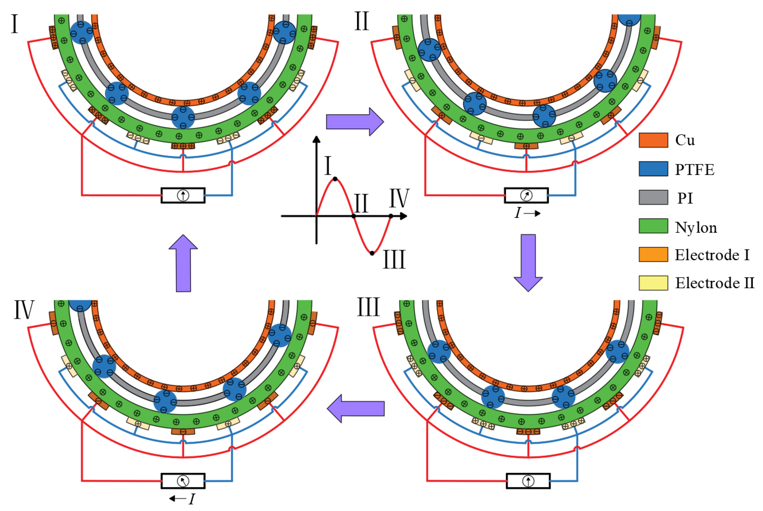
The proposed deep groove ball bearing structure triboelectric nanogenerator (TENG) is designed based on the dimensions of the traditional industrial deep groove ball bearing model 6208. The dimensions of the fabricated DGTG are listed as follows: ball diameter d b   = 8 mm, pitch diameter D m   = 60 mm, and contact angle α = 0°. The number of balls is N b a l l = 9. A 3D schematic diagram of the structure is shown in Figure 1, where, from left to right, the components include the copper inner ring, PTFE rolling elements, Polyimide (PI) cage, nylon outer ring, and copper comb-like interlocking electrodes [46,47]. The bearing is manufactured using a machining process and assembled accordingly. To maintain the dimensional assembly of the DGTG, the surfaces of PTFE, copper, and nylon were used as they were without further treatment. The power generation mechanism is illustrated in Figure 2. When the PTFE material comes into contact with the copper inner ring and nylon outer ring, rolling friction occurs. Due to the attraction of positive charges in the copper and nylon materials to the electrons in the PTFE, an electronic transition occurs, generating free electrons. At this point, the surface of the PTFE becomes negatively charged, while electrostatic equilibrium is established between the PTFE, copper electrode 1, nylon outer ring, and copper inner ring, as shown in Figure 2(I). As the rolling element continues to roll between electrode 1 and electrode 2, the equilibrium is disrupted, and the positive charge induced on electrode 1 is attracted by the PTFE rolling element, flowing toward electrode 2, generating a forward current, as shown in Figure 2(II). When the rolling element continues to roll onto electrode 2, a new electrostatic balance forms between the software, and the surface charge density of the PTFE rolling element, along with the suspended potential of the copper electrode, copper inner ring, and nylon outer ring, are set. Finally, the step size is selected for investigation. As shown in Figure 3, the output results from steps I to IV correspond precisely to the power generation mechanism diagram established earlier. When the rolling element is at different positions, the resulting electric field causes continuous variations in the suspended potential of the copper electrode, copper inner ring, and nylon outer ring rolling element, inner and outer rings, and electrode 2, as shown in Figure 2(III). As the rolling element rolls further, the previous electrostatic equilibrium is broken again, and the positive charge in electrode 2 is attracted by the negatively charged rolling element, flowing from electrode 2 to electrode 1, thus generating a reverse current, as shown in Figure 2(IV). These four processes continue cyclically as the rolling element moves, producing an alternating current. This design allows the PTFE rolling element to simultaneously experience rolling friction with both the inner and outer rings, maintaining the maximum surface charge density, thereby enhancing the power generation capability of the device.
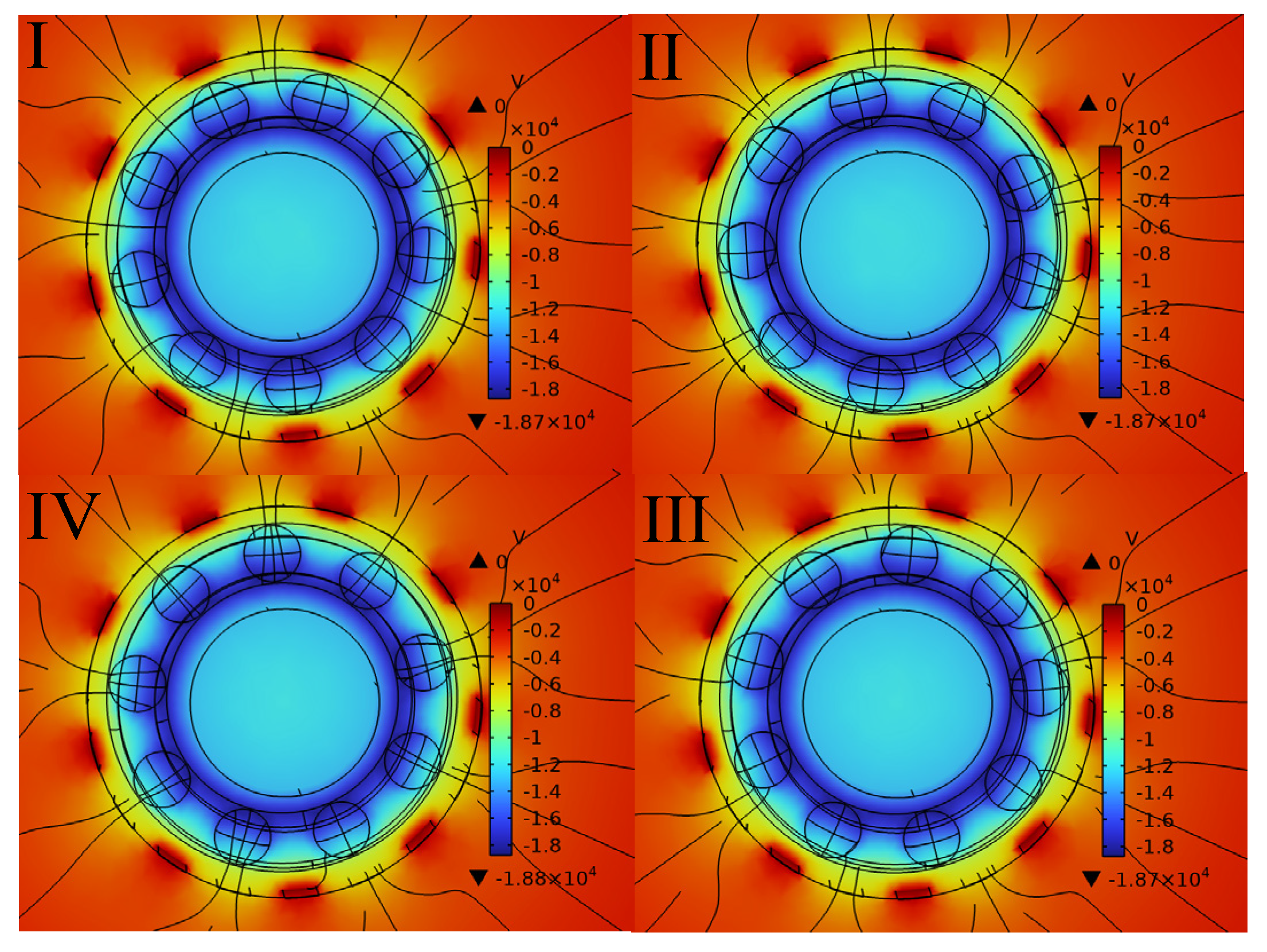
Based on the multi-layer material power generation mechanism of the DGTG, a scaled 3D model is established in the COMSOL6.0 electrostatic field. The material properties of the core components are selected within the software, and the surface charge density of the PTFE rolling element, along with the suspended potential of the copper electrode, copper inner ring, and nylon outer ring, are set. Finally, the step size is selected for investigation. As shown in Figure 3, the output results from steps I to IV correspond precisely to the power generation mechanism diagram established earlier. When the rolling element is at different positions, the resulting electric field causes continuous variations in the suspended potential of the copper electrode, copper inner ring, and nylon outer ring.
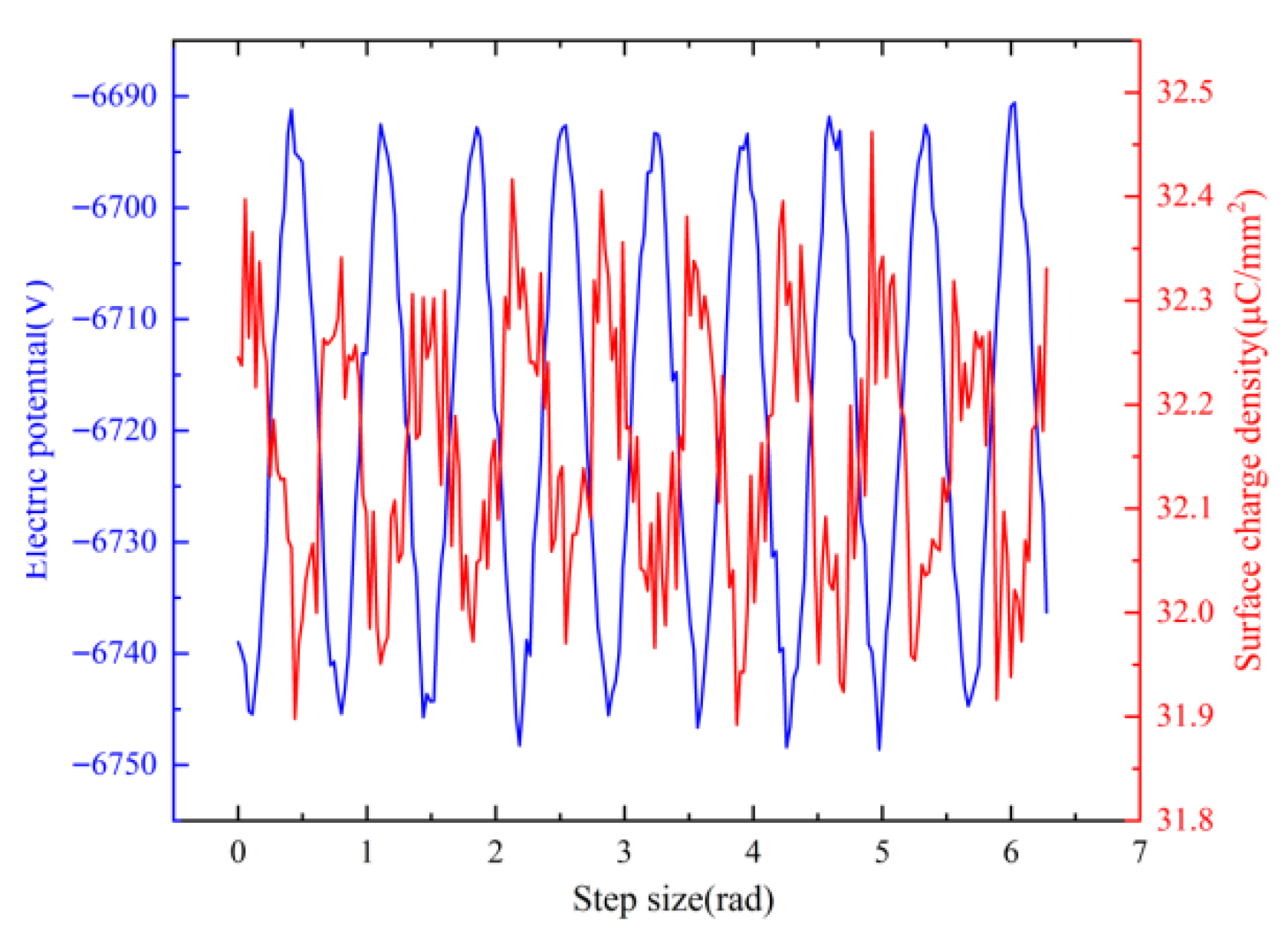
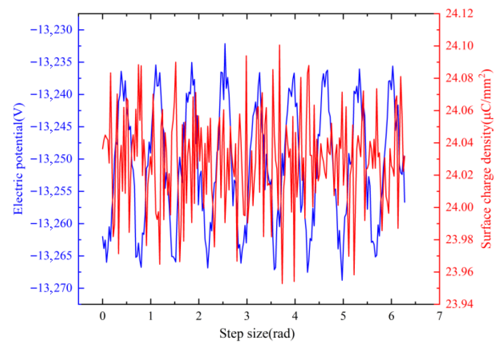
Charge density probes and potential sensors were positioned on copper electrodes and inner rings. The resultant potential and charge density profiles (Figure 4 and Figure 5) indicate that the copper electrodes exhibited greater signal stability due to their multilayered architecture, whereas higher frequency fluctuations were recorded for the copper inner ring. This phenomenon is attributed to the traversal of rolling elements across the inter-electrode gap during movement from Electrode 1 to Electrode 2. Each electrode transition generated a single electrical cycle, whereas the copper inner ring participated in two electrostatic equilibrium-disruption sequences per rotation cycle. Consequently, experimental validation of the power generation mechanism is provided through these characteristic signatures.

3. Results and Discussion

3.1. Output Performance of the DGTG

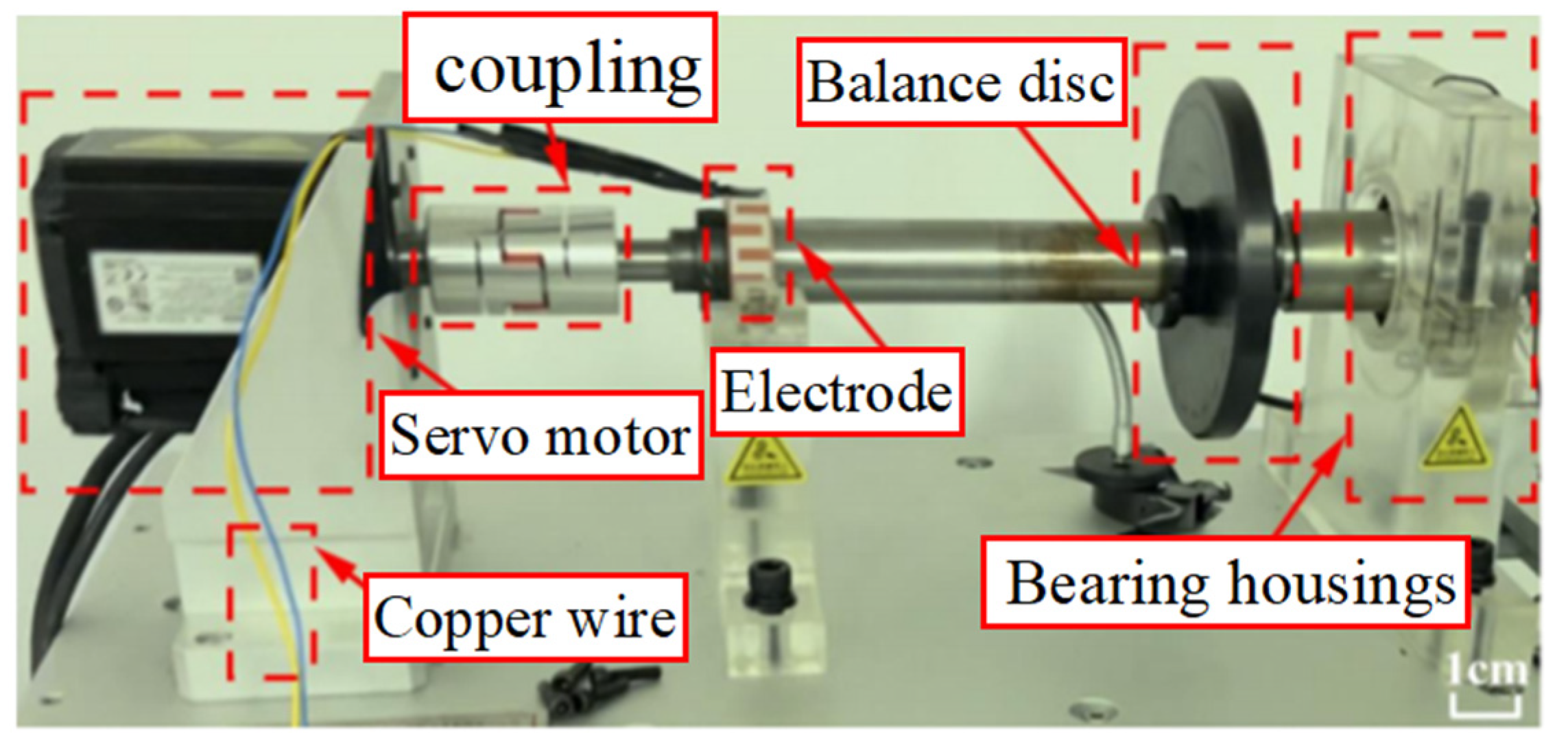
A rotor experimental platform was set up, with a servo motor providing stable rotational speed output and the Keithley 6514 electrometer used to measure the electrical signals. The programmable electrometer (6514, Keithley Instruments model (Solon, OH, USA)) was utilized to test the short circuit current and output charge density of the DGTG. The DGTG was tested for electrical signal output on the established experimental platform, with rotational speeds set over a wide range from 100 to 2000 rpm, which can be found in Figure 6.This test bench is placed horizontally. The DGTG test is conducted under no-load conditions, so the contact pressure is generated by centrifugal force and is affected by the rotational speed. The manufacturing accuracy of the comb-tooth electrode is shown in the processing drawing in Supplementary Figure S1.The real-time monitoring diagram of the experimental temperature and humidity sensor is shown in Supplementary Figure S2,with the temperature and humidity being 297.15 K and 50.4%, respectively.
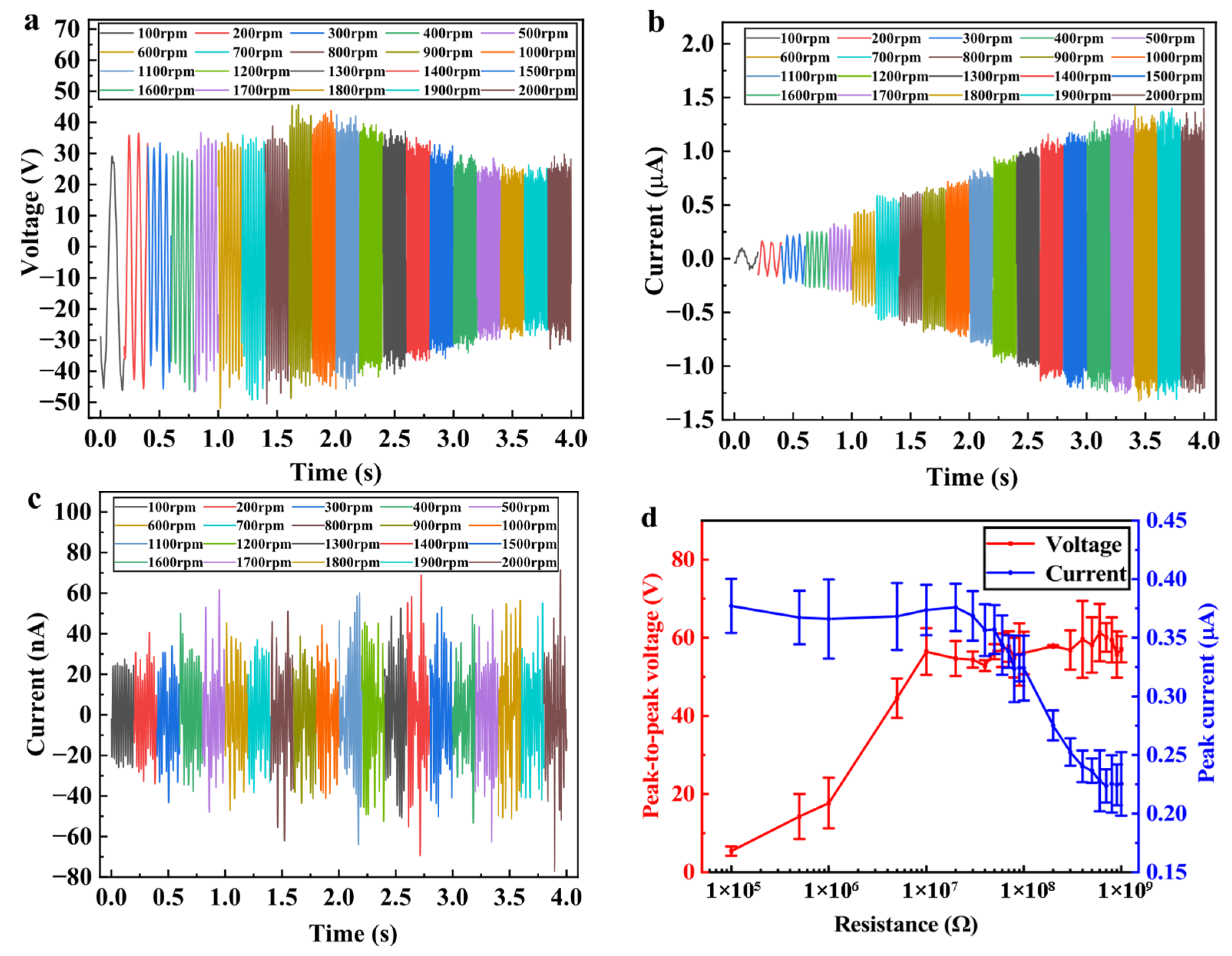
As shown in Figure 7a, the open-circuit voltage of the copper electrode varies with speed, and it is evident that the open-circuit voltage cycle increases with rotational speed over the same time period. It can be observed that when the rotational speed exceeds 900 rpm, the RMS value of the open-circuit voltage decreases in a regular pattern. This could be due to the PTFE rolling element being separated from the copper electrode by the nylon outer ring, which reduces the ability of the rolling element to attract positive charges in the copper electrode as its speed increases.
V O C = 2 σ x ( t ) ε 0
In the equation, the surface charge density of the PTFE and copper electrode is denoted by σ, ε 0 represents the vacuum permittivity, and x ( t ) is the distance traveled by the PTFE rolling element along the raceway. From Equation (1), it can be observed that the open-circuit voltage is not affected by the rotational speed, as it is determined by other factors. Thereore, when the rotational speed exceeds 900 rpm, it is likely to influence the results.
As shown in Figure 7b, the short-circuit current of the copper electrode varies with speed. It is evident that the short-circuit current cycle also increases with rotational speed over the same time period. The relationship between the short-circuit current and the rotational speed is given by:
I S C = Q S C Δ t
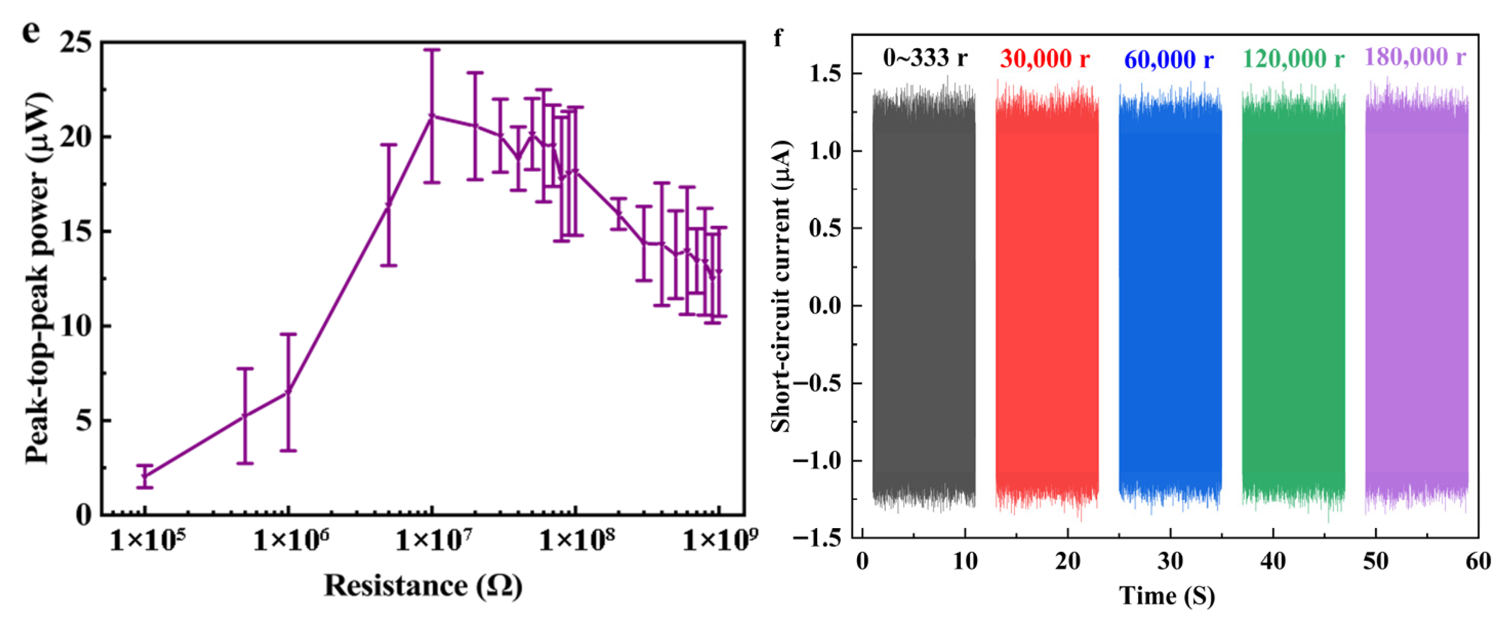
The Qsc defines the short-circuit charge transfer during one rotation cycle, which corresponds to the change in charge density, and Δt represents the time for one rotation cycle. From Equation (2), it is evident that the magnitude of the short-circuit current is proportional to the rotational speed, consistent with the previously presented test results. The COMSOL simulation results indicate that the copper inner ring plays a role in the electrostatic equilibrium and disruption of the DGTG. Based on these simulation results, the variation in charge density on the copper inner ring was measured. The test results, shown in Figure 7c, reveal that the surface charge density on the copper inner ring changes with the rolling motion of the PTFE rolling element, and it also varies with the rotational speed. This validates the correctness of the energy generation mechanism and the reliability of the simulation results. Additionally, it confirms the potential application of the multilayer triboelectric nanogenerator in Figure 7d, which shows the output current and voltage curves of the copper electrode when the motor speed is 500 rpm and the external load increases from 1 × 10⁵ Ω to 1 × 10⁹ Ω. It can be observed that the voltage increases with the load, while the current behaves oppositely. As shown in Figure 7e, when the external load is 1 × 10⁷ Ω, the output reaches the maximum power of 21.1 μW at this speed. Figure 7d,e are obtained from five experiments conducted at a motor speed of 500 rpm, with an experiment duration of 5 s. This demonstrates the promising application prospects of the proposed DGTG in energy harvesting. By adopting a rolling element that does not come into direct contact with the electrode, the DGTG demonstrates excellent durability. It can operate continuously for 180,000 revolutions at a speed of 2000 rpm, and its short-circuit current signal is shown in Figure 7f, maintaining a stable output.

3.2. Analysis of Time–Frequency Characteristics

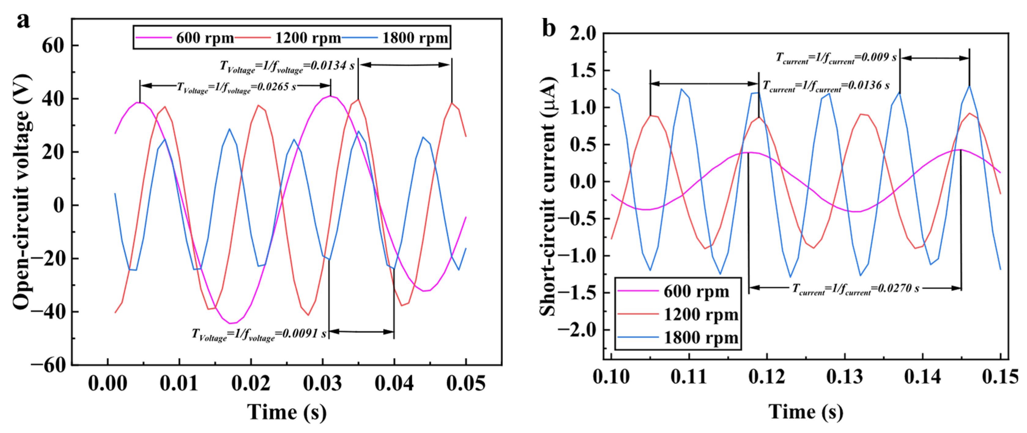
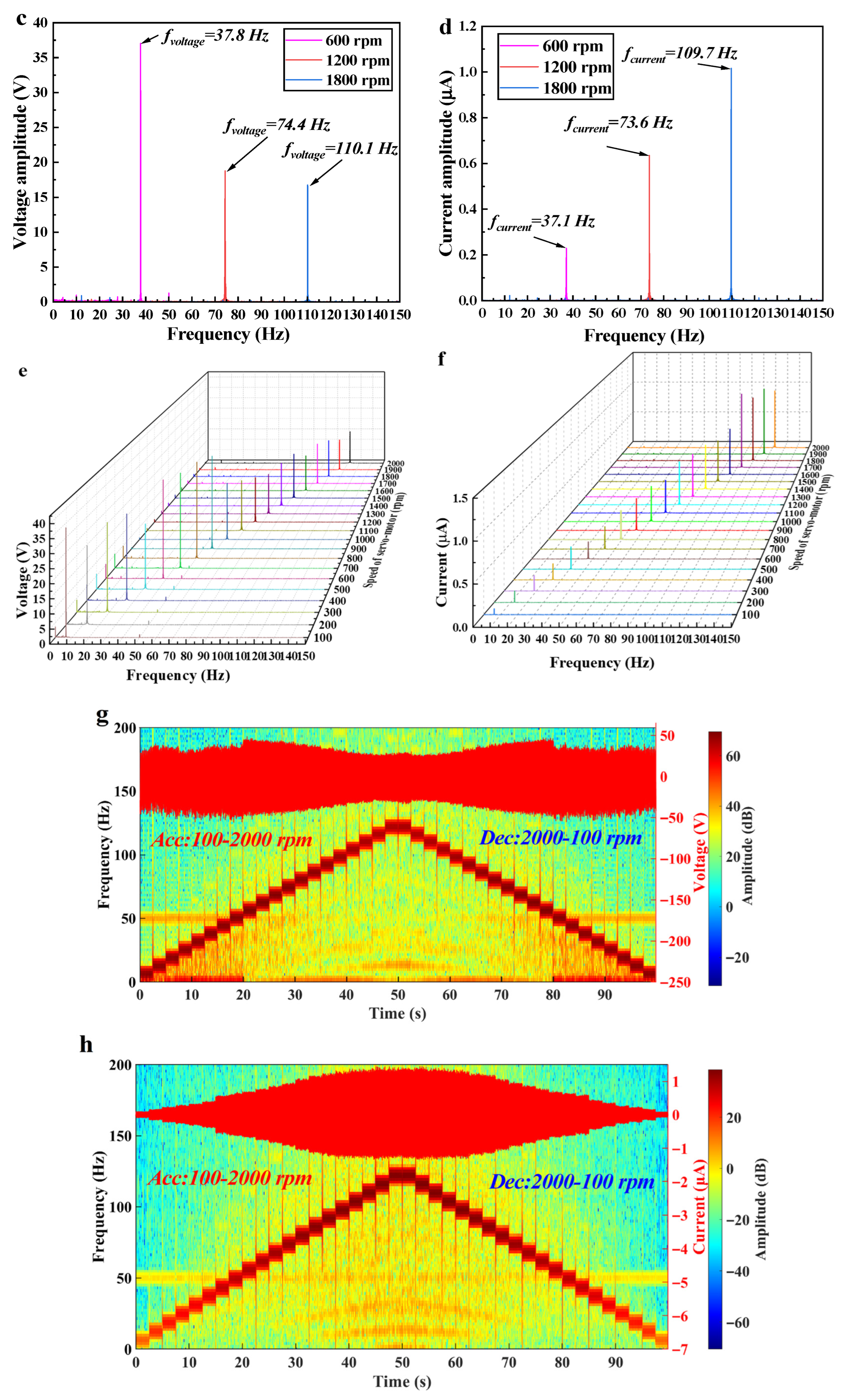
Based on the DGTG structure being the standard deep groove ball bearing 6208, time–frequency domain analysis, commonly used in bearing condition monitoring, is introduced. The characteristic that the electrical signal period increases with rotational speed in the same time period suggests that triboelectric signals can also serve as a means for time–frequency analysis monitoring. As shown in Figure 8a, voltage signal plots at 600 rpm, 1200 rpm, and 1800 rpm over 0.05 s are provided. The following Equation (3) represents:
T V o l t a g e = 1 f V o l t a g e
where f V o l t a g e is the first-order fundamental frequency of the open-circuit voltage signal. According to Figure 8a, the first-order fundamental frequencies of the voltage signal at 600 rpm, 1200 rpm, and 1800 rpm are 37.736 Hz, 74.627 Hz, and 109.890 Hz, respectively. These correspond to the first-order fundamental frequencies of the voltage signal obtained through Fourier transformation at the three rotational speeds shown in Figure 8c. Any errors are likely due to factors such as measurement accuracy and test equipment. However, it can be concluded that the open-circuit voltage frequency domain signal accurately monitors the rolling element’s rotational speed. To further explore the speed monitoring capability of the DGTG for voltage signals, Fourier transforms for speeds between 100 rpm and 2000 rpm are shown in Figure 8e. It can be observed that as the rotational speed increases linearly, the first-order fundamental frequency value of the voltage signal also increases linearly. Additionally, the signal is minimally affected by external factors, and the first-order fundamental frequency is easily measured at all speeds. This validates the one-to-one correspondence between the first-order fundamental frequency of the voltage signal and rotational speed. Based on this study, a MATLAB2022b program was developed to perform real-time Fourier transforms on time–domain signals. As shown in Figure 8g, for varying rotational speeds of the DGTG, the voltage time–domain signal was measured over 100 s by first accelerating and then decelerating. The program can real-time reflect the first-order fundamental frequency of each time–domain segment, providing clear and accurate monitoring of the corresponding roller speed. This program can also monitor the duration of the rolling element at any given speed, proving that the system’s voltage signal, when combined with time–frequency analysis, can efficiently monitor the rolling element’s rotational speed in real-time.
Furthermore, based on the DGTG electrical signal analysis, the RMS value of the current signal increases linearly with rotational speed. However, the current signal is more susceptible to external factors such as temperature and humidity. By utilizing the characteristic that the number of cycles in the current signal increases with rotational speed, we examine how the first-order fundamental frequency of the current signal changes as speed increases. As shown in Figure 8b, the current cycle is measured at rotational speeds of 600 rpm, 1200 rpm, and 1800 rpm. Using the following formula (4):
T C u r r e n t = 1 f C u r r e n t
where f C u r r e n t is the first-order fundamental frequency of the short-circuit current. From Figure 8b, the first-order fundamental frequencies of the current signal at 600 rpm, 1200 rpm, and 1800 rpm are 37.037 Hz, 73.529 Hz, and 111.111 Hz, respectively. These correspond to the first-order fundamental frequencies obtained through Fourier transformation of the current signal at the three rotational speeds, as shown in Figure 8d. Any errors observed can be attributed to the measurement equipment’s accuracy. However, it can be concluded that short-circuit current frequency domain signals also accurately monitor the rolling element’s rotational speed. To further investigate the speed monitoring capability of short-circuit current signals in the DGTG, Fourier transforms for speeds between 100 rpm and 2000 rpm are shown in Figure 8f. It is evident that as the rotational speed increases linearly, the first-order fundamental frequency of the short-circuit current signal also increases linearly. Additionally, the signal is largely unaffected by external factors, and the first-order fundamental frequency is easy to measure at all speeds. This verifies that the first-order fundamental frequency of the current signal has a one-to-one correspondence with rotational speed. Following the study, a MATLAB program was used to perform real-time Fourier transforms of the time–domain signals. This program can process time–domain signals in real time and display the corresponding frequency–domain graph below. The program is provided by Supplementary Material S3. As shown in Figure 8h, for varying rotational speeds of the DGTG, the short-circuit current time–domain signal was measured over 100 s by first accelerating and then decelerating. The program can real-time display the first-order fundamental frequency of each time–domain segment, allowing for clear and accurate monitoring of the corresponding roller speed. Additionally, this program can monitor the duration of the rolling element at a specific speed, further confirming that the short-circuit current signal, through time–frequency analysis, can monitor the rolling element’s rotational speed in real-time.

3.3. Analysis of Skidding Monitoring Characteristics

Based on time–frequency domain characteristics, it can be concluded that the DGTG can serve as a self-sensing rotational speed sensor for rolling elements, utilizing the first-order fundamental frequency to monitor the rolling element’s rotational speed in real-time. The theoretical calculation formula for the rolling element’s rotational speed frequency in the deep groove ball bearing 6208 is given by Equation (5):
f C a l c u l a t e d = N B a l l 2 f M o t o r ( 1 d b D m cos α )
where f M o t o r is the motor speed frequency, N B a l l is the number of rolling elements (9 in this case), d b is the rolling element diameter (8 mm), D m is the pitch diameter (60 mm), and α is the contact angle (0°).
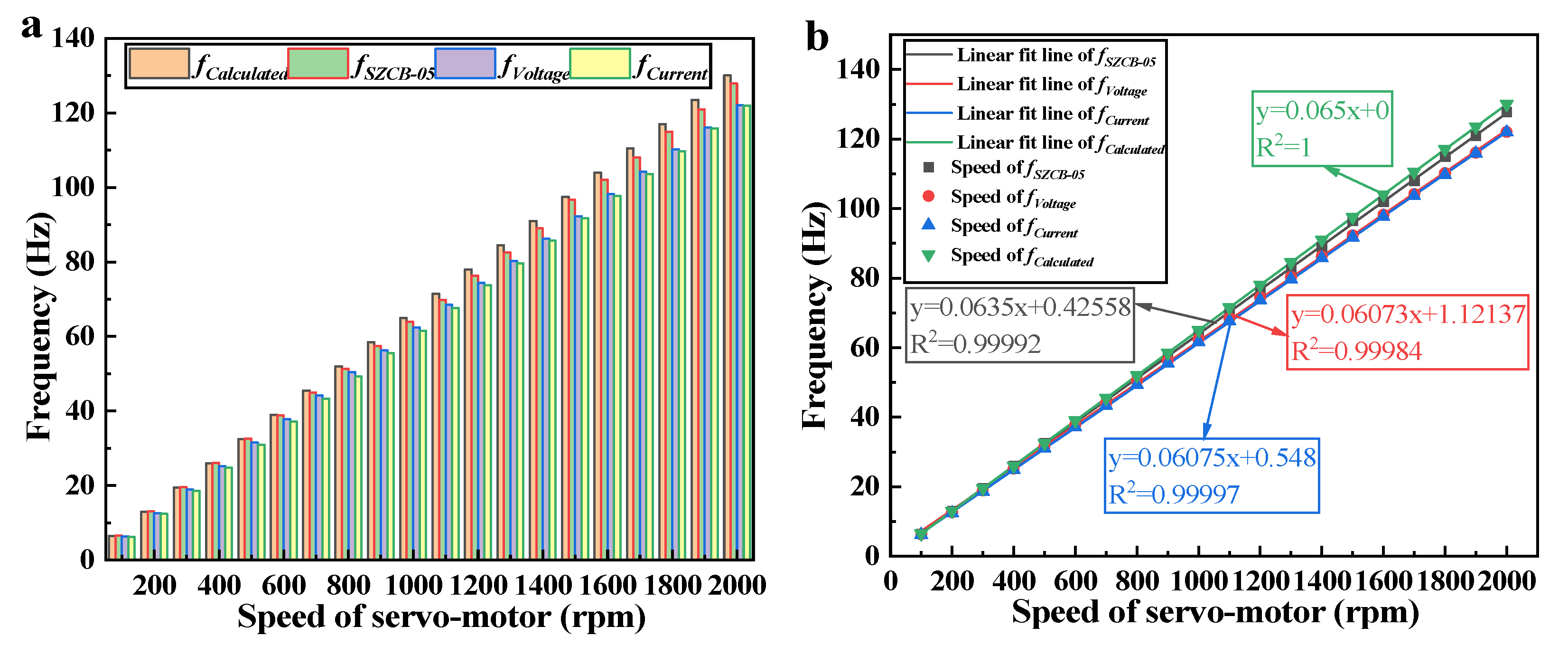
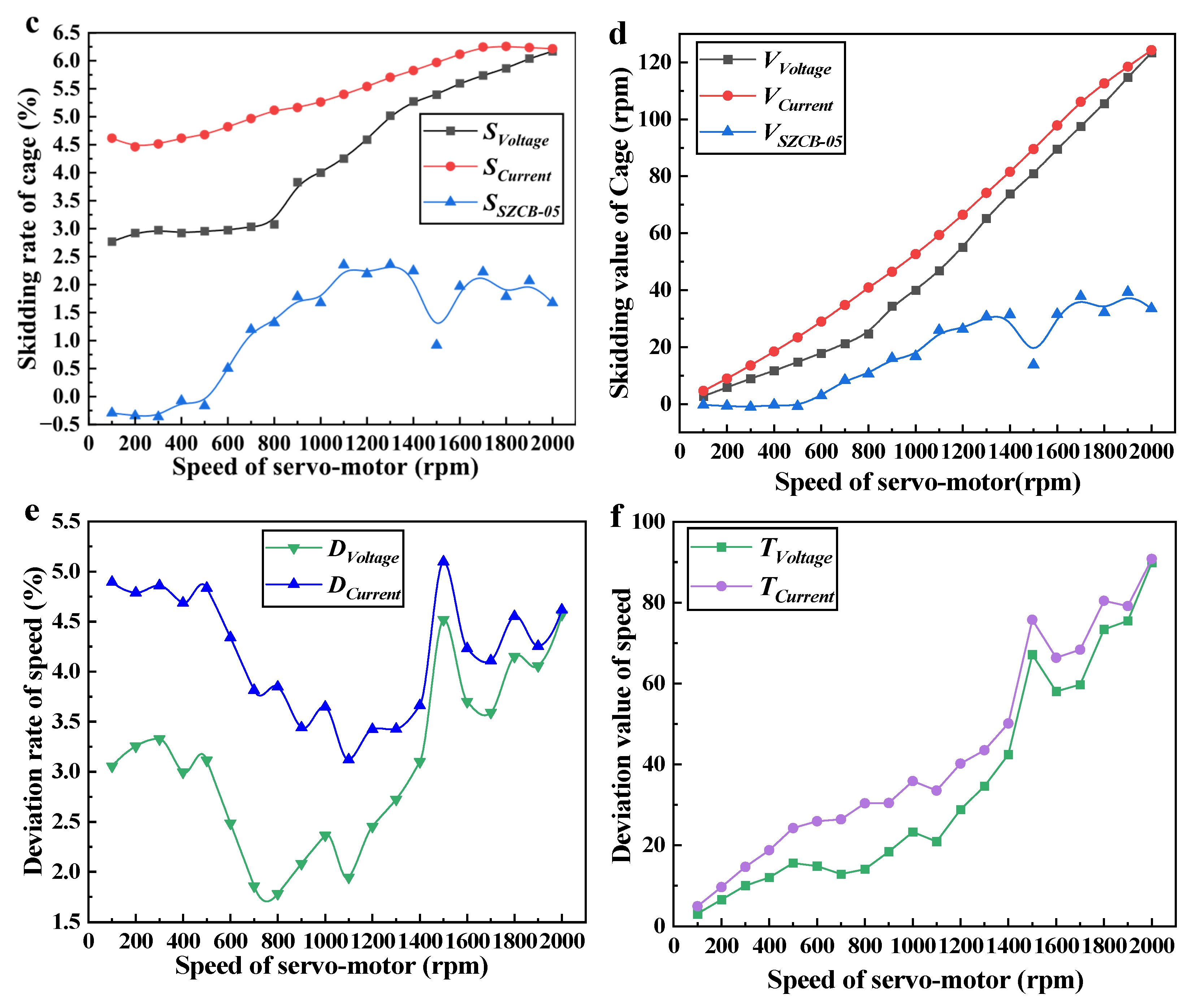
By comparing the data in Figure 9a, it can be observed that as the rotational speed increases, the frequency values of the four signals diverge more significantly. This is due to slippage occurring between the rolling elements, cage, and the inner/outer rings of the DGTG. Furthermore, as the speed increases, the degree of slippage also increases, which causes the measured frequency values to be lower than the theoretical calculated values. Based on the time–frequency characteristics of the DGTG, it was found that both the open-circuit voltage signal and short-circuit current signal show a strong linear relationship with rotational speed. Additionally, the frequency domain of the electrical signal is stable and minimally affected by external factors, making it easy to measure the first-order fundamental frequency value. The photoelectric speed sensor SZCB-05 also shows a good linear fit between the measured cage speed frequency and motor speed. The photoelectric speed sensor SZCB-05 is produced and calibrated by Wuxi Houde Automation Meter Co., Ltd., Wuxi, China, with a response frequency ranging from 2 HZ to 1k HZ. As shown in Figure 9b, the green curve represents the theoretical frequency of the cage versus motor speed, with an R2 = 1; the gray curve represents the measured cage speed frequency vs. motor speed from the SZCB-05 sensor, with R2 = 0.99992; the red curve shows the fit for the open-circuit voltage signal relative to the roller’s rotational speed frequency and motor speed, with R2 = 0.99984; and the blue curve represents the fit for the short-circuit current signal relative to the roller’s rotational speed frequency and motor speed, with R2 = 0.99997. It is evident that both the SZCB-05 sensor monitoring cage speed and the electrical signals monitoring roller rotational speed exhibit a strong linear relationship with motor speed. This confirms that the proposed device’s electrical signals provide accurate monitoring of both roller rotational speed and motor speed. Notably, the fitting coefficient for the short-circuit current signal is even higher than that of the traditional photoelectric speed sensor, demonstrating the superior performance of the proposed device in bearing speed monitoring. The deviation between the fundamental frequencies of the electrical signals from the DGTG, the measurements from the photoelectric speed sensor, and the theoretical calculations shows that the device can monitor its own slippage condition. As shown in Figure 9c, the difference rate between the rotational speed values measured by the open-circuit voltage and short-circuit current signals, the cage speed measured by the photoelectric sensor SZCB-05, and the theoretical cage speed is illustrated. The calculation formula is given by Equation (6):
S = ω ω ω 100 %
V = ω ω
The theoretical rotational speed is denoted by ω , and the experimentally measured rotational speed is denoted by ω . As shown in Figure 9d, the difference between the rotational speed values measured by the open-circuit voltage and short-circuit current signals, as well as the cage speed measured by the photoelectric speed sensor SZCB-05, and the theoretical cage speed is calculated according to Equation (7). From the figure, it can be observed that the slippage rate measurements for all three signals increase initially with motor speed and then stabilize. Furthermore, the slippage values increase with motor speed. This confirms that as the operating speed increases, the degree of slippage in the device also increases. Additionally, it can be observed that the slippage rate and slippage values measured by the short-circuit current and open-circuit voltage signals are similar and both higher than those measured by the SZCB-05 sensor. This difference may be due to the wider reflective tape used by the photoelectric speed sensor, which introduces measurement errors. In summary, based on the theoretical calculation of the cage speed, the electrical signals output by the proposed DGTG exhibit excellent performance in monitoring the degree of slippage, with the ability to monitor slippage values and rates in real time across various rotational speeds. From the above research on the speed monitoring performance of the DGTG, it is evident that the device’s electrical signals perform well in monitoring both the roller’s rotational speed and the motor speed. Compared to the traditional industrial photoelectric speed sensor SZCB-05, which externally monitors the cage, the integrated design within the bearing saves installation space and offers broader application prospects. As shown in Figure 9e, the difference rate between the roller’s rotational speed measured by the device and the cage speed measured by the SZCB-05 sensor is consistently less than 5.5% across different speeds. As shown in Figure 9f, the difference between the roller’s rotational speed measured by the device and the cage speed measured by the SZCB-05 increases with speed. This is due to the width of the copper electrode’s placement on the outer ring, which reduces the detection accuracy of the device. However, overall, the open-circuit voltage demonstrates superior rotational speed-monitoring performance compared to the short-circuit current signal.

4. Conclusions

This paper presents a multilayer material-based DGTG, utilizing a sliding independent layer mode suitable for industrial bearing structures. The copper electrode is mounted on the outer ring to address the issue of electrode wear. At the same time, the proposed multilayer materials allow multiple components of the bearing to participate in the formation and disruption of electrostatic equilibrium. The addition of a copper inner ring replenishes the surface charge of the PTFE rolling element, improving the open-circuit voltage output. The experimental setup integrates the photoelectric speed sensor SZCB-05 for comparison. Experimental results show that the open-circuit voltage RMS value exceeds 30 V at the test speeds. When the motor speed is 500 rpm and the external load is 1 × 10⁷ Ω, the maximum output power reaches 21.1 μW at this speed. Subsequent time–frequency domain analysis of the electrical output signals reveals that the open-circuit voltage and short-circuit current signals exhibit a fitting coefficient of R2 = 0.99984 and R2 = 0.99997, respectively, for the roller’s rotational speed frequency and motor speed, thus validating the real-time monitoring capability of these electrical signals for both roller and motor speeds. A MATLAB program was developed to create a real-time time–frequency domain analysis monitoring module for electrical signals with varying speeds. Finally, based on the theoretical model for bearing slippage in deep groove ball bearings, the ability of the open-circuit voltage, short-circuit current, and photoelectric speed sensor to monitor bearing slippage conditions was verified. By comparing the measurement differences between the electrical signals and the industrial photoelectric speed sensor, the difference rate between the three signals was found to be consistently below 5.5%. Overall, the open-circuit voltage demonstrated superior rotational speed monitoring performance compared to the short-circuit current signal. The proposed DGTG, with its integrated internal design, effectively solves the problem of space occupation associated with externally installed sensors.

Supplementary Materials

The following supporting information can be downloaded at: https://www.mdpi.com/article/10.3390/machines13090875/s1, Figure S1: Copper electrode processing drawings of the DGTG; Figure S2: Integrated temperature and humidity sensors for the DGTG test bench; S3: A MATLAB2022b program.

Author Contributions

Conceptualization, Z.Z. and L.W.; methodology, Z.Z.; software, L.W.; validation, Z.Z., L.W. and Z.W.; formal analysis, Z.W.; investigation, L.W.; resources, Z.Z.; data curation, Z.W.; writing—original draft preparation, Z.Z.; writing—review and editing, L.W.; visualization, F.W.; supervision, F.W. All authors have read and agreed to the published version of the manuscript.

Funding

The research work described in the paper was supported by the National Natural Science Foundation of China (51905001), and the Enterprise Cooperation Project of Anhui Future Technology Research Institute (2023qyhz22), the Key Project of Outstanding Young Teachers Training Action of Young and Middle-aged Teachers of Anhui Province (YQZD2023044), the Key Project of Scientific Research in Colleges and Universities of Anhui Provincial Department of Education (KJ2021A1326), Funding Project for Cultivation of Outstanding Top Talents in Colleges and Universities of Anhui Province (gxbjZD2022114), and Wuhu Automotive Engineering Technology R&D Center (WHSYFZX202301).

Data Availability Statement

The raw data supporting the conclusions of this article will be made available by the authors on request.

Conflicts of Interest

The authors declare no conflicts of interest.

Abbreviations

The following abbreviations are used in this manuscript:
TENGTriboelectric nanogenerator
DGTGDeep groove ball triboelectric nanogenerator
PTFEPolytetrafluoroethylene
RMSRoot mean square

References

  1. Wang, K.; Huang, Y.; Luo, H. TFASOT for bearing damage feature extraction and enhancement under complex working conditions. Meas. Sci. Technol. 2024, 35, 096121. [Google Scholar] [CrossRef]
  2. Marsick, A.; André, H.; Khelf, I.; Leclère, Q.; Antoni, J. Restoring cyclostationarity of rolling element bearing signals from the instantaneous phase of their envelope. Mech. Syst. Signal Process. 2023, 193, 110264. [Google Scholar] [CrossRef]
  3. Chen, H.; Liu, Y.; Liang, H.; Zhang, H.; Wang, W. The cage instability of angular contact ball bearing under high speed conditions. Mech. Mach. Theory 2024, 197, 105646. [Google Scholar] [CrossRef]
  4. Liu, K.; Wang, D.; Chen, B.; Shi, X.; Feng, Y.; Li, W. Vibration characteristics investigation of a single/dual rotor-bearing-casing system with local bearing defects. Mech. Syst. Signal Process. 2024, 225, 112227. [Google Scholar] [CrossRef]
  5. Xu, M.; Wang, M.; He, D.; Ding, X.; Shao, Y.; Gu, F. Skidding behavior of lubricated rolling element bearings under the influence of oil film and radial clearances. Tribol. Int. 2024, 194, 109500. [Google Scholar] [CrossRef]
  6. Gao, S.; Chatterton, S.; Pennacchi, P.; Han, Q.; Chu, F. Skidding and cage whirling of angular contact ball bearings: Kinematic-hertzian contact-thermal-elasto-hydrodynamic model with thermal expansion and experimental validation. Mech. Syst. Signal Process. 2022, 166, 108427. [Google Scholar] [CrossRef]
  7. Shi, J.; Yu, Y.; Jiang, X.; Li, C.; Shen, C.; Huang, W.; Zhu, Z. Dynamic modeling considering time-varying contact pairs and parameterized defects of deep groove ball bearings for its vibration characteristic analysis. Nonlinear Dyn. 2024, 112, 17781–17809. [Google Scholar] [CrossRef]
  8. Xu, M.; Han, Y.; Sun, X.; Shao, Y.; Gu, F.; Ball, A.D. Vibration characteristics and condition monitoring of internal radial clearance within a ball bearing in a gear-shaft-bearing system. Mech. Syst. Signal Process. 2022, 165, 108280. [Google Scholar] [CrossRef]
  9. Liu, Y.; Wang, W.; Qing, T.; Zhang, Y.; Liang, H.; Zhang, S. The effect of lubricant temperature on dynamic behavior in angular contact ball bearings. Mech. Mach. Theory 2019, 149, 103832. [Google Scholar] [CrossRef]
  10. Aretusini, S.; Cascajero, A.; Cornelio, C.; Echevarria, X.; Spagnuolo, E.; Tapetado, A.; Vazquez, C.; Di Toro, G.; Cocco, M. Mechanical Energy Dissipation During Seismic Dynamic Weakening in Calcite-Bearing Faults. J. Geophys. Res. Solid Earth 2024, 129, e2024JB028927. [Google Scholar] [CrossRef]
  11. Zhang, P.; Zhou, W.; Yin, H.; Shang, Y. Progressive damage analysis of three-dimensional braided composites under flexural load by micro-CT and acoustic emission. Compos. Struct. 2019, 226, 111196. [Google Scholar] [CrossRef]
  12. Dai, P.; Liang, X.; Wang, J.; Wang, F.; Niu, L. The acoustic-vibration characteristics of cylindrical roller bearings with raceway failures: Simulation and experiment. Measurement 2024, 234, 114918. [Google Scholar] [CrossRef]
  13. Zhang, X.; Zhu, Q.; Wang, S.; Ma, T.; Gao, S.; Kong, Y.; Han, Q.; Chu, F. Hybrid triboelectric-variable reluctance generator assisted wireless intelligent condition monitoring of aero-engine main bearings. Nano Energy 2025, 136, 110721. [Google Scholar] [CrossRef]
  14. Gao, S.; Han, Q.; Jiang, Z.; Zhang, X.; Pennacchi, P.; Chu, F. Triboelectric based high-precision self-powering cage skidding sensor and application on main bearing of jet engine. Nano Energy 2022, 99, 107387. [Google Scholar] [CrossRef]
  15. Gao, S.; Ma, T.; Zhou, N.; Feng, J.; Pu, H.; Luo, J.; Pennacchi, P.; Chu, F.; Han, Q. Extremely compact and lightweight triboelectric nanogenerator for spacecraft flywheel system health monitoring. Nano Energy 2024, 122, 109330. [Google Scholar] [CrossRef]
  16. Fan, F.; Tian, Z.; Wang, Z. Flexible triboelectric generator. Nano Energy 2012, 1, 328–334. [Google Scholar] [CrossRef]
  17. Song, M.; Chung, J.; Chung, S.; Cha, K.; Heo, D.; Kim, S.; Hwang, P.; Kim, D.; Koo, B.; Hong, K.; et al. Semisolid-lubricant-based ball-bearing triboelectric nanogenerator for current amplification, enhanced mechanical lifespan, and thermal stabilization. Nano Energy 2021, 93, 106816. [Google Scholar] [CrossRef]
  18. Xie, Z.; Wang, Y.; Yu, M.; Yu, D.; Lv, J.; Yin, J.; Liu, J.; Wu, R. Triboelectric sensor for planetary gear fault diagnosis using data enhancement and CNN. Nano Energy 2022, 103, 107804. [Google Scholar] [CrossRef]
  19. Ruan, S.; Gao, S.; Feng, J.; Kong, Y.; Han, Q.; Chu, F. Intelligent triboelectric V-belts with condition monitoring capability. Mech. Syst. Signal Process. 2024, 209, 111132. [Google Scholar] [CrossRef]
  20. Gao, S.; Zhang, R.; Wu, F.; Luo, J.; Pu, H.; Chu, F.; Han, Q. Rotating single-electrode triboelectric V-belts with skidding and wear monitoring capabilities. Tribol. Int. 2024, 193, 109404. [Google Scholar] [CrossRef]
  21. Jin, T.; Sun, Z.; Li, L.; Zhang, Q.; Zhu, M.; Zhang, Z.; Yuan, G.; Chen, T.; Tian, Y.; Hou, X.; et al. Triboelectric nanogenerator sensors for soft robotics aiming at digital twin applications. Nat. Commun. 2020, 11, 5381. [Google Scholar] [CrossRef]
  22. Xie, M.; Zhu, M.; Yang, Z.; Okada, S.; Kawamura, S. Flexible self-powered multifunctional sensor for stiffness-tunable soft robotic gripper by multimaterial 3D printing. Nano Energy 2021, 79, 105438. [Google Scholar] [CrossRef]
  23. Liu, D.; Gao, Y.; Zhou, L.; Wang, J.; Wang, Z. Recent advances in high-performance triboelectric nanogenerators. Nano Res. 2023, 16, 11698–11717. [Google Scholar] [CrossRef]
  24. Li, Z.; Yu, A.; Zhang, Q.; Zhai, J. Recent advances in fabricating high-performance triboelectric nanogenerators via modulating surface charge density. Int. J. Extrem. Manuf. 2024, 6, 052003. [Google Scholar] [CrossRef]
  25. Cao, X.; Xiong, Y.; Sun, J.; Xie, X.; Sun, Q.; Wang, Z. Multidiscipline Applications of Triboelectric Nanogenerators for the Intelligent Era of Internet of Things. Nano-Micro Lett. 2022, 15, 14. [Google Scholar] [CrossRef]
  26. Li, Y.; Luo, Y.; Deng, H.; Shi, S.; Tian, S.; Wu, H.; Tang, J.; Zhang, C.; Zhang, X.; Zha, J.; et al. Advanced Dielectric Materials for Triboelectric Nanogenerators: Principles, Methods and Applications. Adv. Mater. 2024, 36, e2314380. [Google Scholar] [CrossRef]
  27. Fang, L.; Zheng, Q.; Hou, W.; Zheng, L.; Li, H. A self-powered vibration sensor based on the coupling of triboelectric nanogenerator and electromagnetic generator. Nano Energy 2022, 97, 107164. [Google Scholar] [CrossRef]
  28. Zhang, X.; Li, H.; Gao, Q.; Yuan, Z.; He, S.; Yu, X.; Wang, L.; Cheng, T. Self-powered triboelectric mechanical motion sensor for simultaneous monitoring of linear-rotary multi-motion. Nano Energy 2023, 108, 108239. [Google Scholar] [CrossRef]
  29. Zhu, Q.; Zhu, L.; Wang, Z.; Zhang, X.; Li, Q.; Han, Q.; Yang, Z.; Qin, Z. Hybrid triboelectric-piezoelectric nanogenerator assisted intelligent condition monitoring for aero-engine pipeline system. Chem. Eng. J. 2025, 519, 165121. [Google Scholar] [CrossRef]
  30. Jung, H.; Friedman, B.; Hwang, W.; Copping, A.; Branch, R.; Deng, D. Self-powered arctic satellite communication system by harvesting wave energy using a triboelectric nanogenerator. Nano Energy 2023, 114, 108633. [Google Scholar] [CrossRef]
  31. Liu, Y.; Zhang, D.; Ji, X.; Xu, Z.; Zhang, H.; Mao, R.; Liu, W.; Wang, J.; Sun, Y. Rotational contact triboelectric nanogenerator driven by water flows inspired by waterwheels and their applications for lead ion removal. Nano Energy 2024, 128, 109800. [Google Scholar] [CrossRef]
  32. Yin, M.; Yu, Y.; Wang, Y.; Wang, Z.; Lu, X.; Cheng, T.; Wang, Z. Multi-plate structured triboelectric nanogenerator based on cycloidal displacement for harvesting hydroenergy. Extrem. Mech. Lett. 2019, 33, 100576. [Google Scholar] [CrossRef]
  33. Zhao, D.; Li, H.; Yu, Y.; Wang, Y.; Wang, J.; Gao, Q.; Wang, Z.; Wen, J.; Cheng, T. A current-enhanced triboelectric nanogenerator with crossed rollers for harvesting wave energy. Nano Energy 2023, 117, 108885. [Google Scholar] [CrossRef]
  34. Zhu, M.; Zhang, J.; Wang, Z.; Yu, X.; Zhang, Y.; Zhu, J.; Wang, Z.; Cheng, T. Double-blade structured triboelectric–electromagnetic hybrid generator with aerodynamic enhancement for breeze energy harvesting. Appl. Energy 2022, 326, 119970. [Google Scholar] [CrossRef]
  35. Wang, Y.; Cai, S.; Wang, Y.; Wu, D.; Xiang, G.; Yang, S.; Zhang, J.; Dai, S.; Xu, M.; Xiang, X. Study on dynamics and power generation performance coupling of galloping-based triboelectric nanogenerator for harvesting broadband wind energy. Nano Energy 2024, 130, 110126. [Google Scholar] [CrossRef]
  36. Mu, S.; Li, S.; Zhao, H.; Wang, Z.; Xiao, X.; Xiao, X.; Lin, Z.; Song, Z.; Tang, H.; Xu, Q.; et al. A platypus-inspired electro-mechanosensory finger for remote control and tactile sensing. Nano Energy 2023, 116, 108790. [Google Scholar] [CrossRef]
  37. Liu, J.; Xu, P.; Zheng, J.; Liu, X.; Wang, X.; Wang, S.; Guan, T.; Xie, G.; Xu, M. Whisker-inspired and self-powered triboelectric sensor for underwater obstacle detection and collision avoidance. Nano Energy 2022, 101, 107633. [Google Scholar] [CrossRef]
  38. Wang, S.; Xu, P.; Wang, X.; Zheng, J.; Liu, X.; Liu, J.; Chen, T.; Wang, H.; Xie, G.; Tao, J.; et al. Underwater bionic whisker sensor based on triboelectric nanogenerator for passive vortex perception. Nano Energy 2022, 97, 107210. [Google Scholar] [CrossRef]
  39. Choi, D.; Sung, T.; Kwon, J. A self-powered smart roller-bearing based on a triboelectric nanogenerator for measurement of rotation movement. Adv. Mater. Technol. 2018, 3, 1800219. [Google Scholar] [CrossRef]
  40. Xin, Y.; Du, T.; Liu, T.; Sun, P.; Zhu, M.; Zheng, L.; Du, H.; Zou, Y.; Xu, M. Triboelectric nanogenerator embedded cylindrical roller bearing for rotational energy harvesting and self-powered fault diagnosis. Sens. Actuators A Phys. 2023, 362, 114664. [Google Scholar] [CrossRef]
  41. Yan, J.; Tang, Z.; Zhang, C.; Long, Y.; Li, J.; Sheng, Y. Study of wind energy harvesting based on rolling bearing type triboelectric nanogenerator. Energy Rep. 2024, 12, 3690–3699. [Google Scholar] [CrossRef]
  42. Han, Q.; Ding, Z.; Qin, Z.; Wang, T.; Xu, X.; Chu, F. A triboelectric rolling ball bearing with self-powering and self-sensing capabilities. Nano Energy 2020, 67, 104277. [Google Scholar] [CrossRef]
  43. Xie, Z.; Wang, Y.; Wu, R.; Yin, J.; Yu, D.; Liu, J.; Cheng, T. A high-speed and long-life triboelectric sensor with charge supplement for monitoring the speed and skidding of rolling bearing. Nano Energy 2022, 92, 106747. [Google Scholar] [CrossRef]
  44. Jiang, Z.; Gao, S.; Kong, Y.; Pennacchi, P.; Chu, F.; Han, Q. Ultra-compact triboelectric bearing based on a ribbon cage with applications for fault diagnosis of rotating machinery. Nano Energy 2022, 99, 107263. [Google Scholar] [CrossRef]
  45. Gao, S.; Han, Q.; Zhang, X.; Pennacchi, P.; Chu, F. Ultra-high-speed hybrid ceramic triboelectric bearing with real-time dynamic instability monitoring. Nano Energy 2022, 103, 107759. [Google Scholar] [CrossRef]
  46. Zhao, Z.; Zhou, L.; Li, S.; Liu, D.; Li, Y.; Gao, Y.; Liu, Y.; Dai, Y.; Wang, J.; Wang, Z. Selection rules of triboelectric materials for direct-current triboelectric nanogenerator. Nat. Commun. 2021, 12, 4686. [Google Scholar] [CrossRef]
  47. He, W.; Liu, W.; Chen, J.; Wang, Z.; Liu, Y.; Pu, X.; Yang, H.; Tang, Q.; Yang, H.; Guo, H.; et al. Boosting output performance of sliding mode triboelectric nanogenerator by charge space-accumulation effect. Nat. Commun. 2020, 11, 4277. [Google Scholar] [CrossRef]
Figure 1. 3D structure of DGTG.
Machines 13 00875 g001
Figure 2. Power generation mechanism of the DGTG.
Machines 13 00875 g002
Figure 3. COMSOL electrostatic field simulation of potential.
Machines 13 00875 g003
Figure 4. Potential and charge density profiles of copper electrodes.
Machines 13 00875 g004
Figure 5. Potential and charge density profiles of the copper inner ring.
Machines 13 00875 g005
Figure 6. Schematic of the multilayered triboelectric rolling bearing test platform.
Machines 13 00875 g006
Figure 7. (a) Open-circuit voltage variation with speed, (b) short-circuit current variation with speed, (c) current variation on the copper inner ring with speed, (d) output voltage and current with external load at 500 rpm, (e) power output variation with external load at 500 rpm, (f) short-circuit current signal diagram of the DGTG operating continuously at 180,000 revolutions.
Machines 13 00875 g007aMachines 13 00875 g007b
Figure 8. (a) Voltage period at three speeds, (b) current period at three speeds, (c) voltage frequency at three speeds, (d) current frequency at three speeds, (e) voltage signal frequency at different speeds, (f) current signal frequency at different speeds, (g) voltage signal time–frequency domain analysis for varying speeds, (h) current signal time–frequency domain analysis for varying speeds.
Machines 13 00875 g008aMachines 13 00875 g008b
Figure 9. (a) Comparison of theoretical and experimental first-order fundamental frequency vs. motor speed, (b) linear fitting of theoretical and experimental frequencies vs. motor speed, (c) comparison of slippage rate measurements by electrical signals and sensors, (d) comparison of slippage values by electrical signals and sensors, (e) difference rate between electrical signals and sensors, (f) difference between electrical signals and sensors.
Machines 13 00875 g009aMachines 13 00875 g009b
Disclaimer/Publisher’s Note: The statements, opinions and data contained in all publications are solely those of the individual author(s) and contributor(s) and not of MDPI and/or the editor(s). MDPI and/or the editor(s) disclaim responsibility for any injury to people or property resulting from any ideas, methods, instructions or products referred to in the content.