Article

Optimal Scaling Parameter Analysis for Optical Mirror Processing Robots via Adaptive Differential Evolution Algorithm

1
School of Mechanical and Electronic Engineering, Suzhou University, Suzhou 234000, China
2
Suzhou University Technology and Research Center of Engineering Tribology, Suzhou University, Suzhou 234000, China
3
School of Information Engineering, Suzhou Vocational College of Civil Aviation, Suzhou 234000, China
*
Author to whom correspondence should be addressed.
Machines 2025, 13(9), 853; https://doi.org/10.3390/machines13090853
Submission received: 17 August 2025 / Revised: 12 September 2025 / Accepted: 12 September 2025 / Published: 15 September 2025
(This article belongs to the Section Robotics, Mechatronics and Intelligent Machines)

Abstract

In large optical mirror processing (LOMP), the robot is required to carry a computer-controlled optical surfacing (CCOS) polishing tool capable of both fully covering the required material removal profile and maintaining sufficient redundancy for process adaptability. The designed LOMP robot is a five-degree-of-freedom (5-DOF) hybrid robot, where the workspace of its parallel mechanism is constrained by dimensional parameters, including the moving platform radius, the fixed/moving platform radius ratio, and link lengths. This paper presents an optimization study of dimensional parameters for robotic systems, aimed at meeting the workspace requirements of 1250 mm-diameter large optical mirrors. First, analytical models of the robot’s effective workspace and driving torque under different dimensional parameters are derived. Subsequently, workspace requirements and driving torque are established as optimization constraints, and a differential evolution algorithm is implemented to determine the optimal dimensional parameters for the LOMP system. To improve computational efficiency, the conventional differential evolution algorithm is enhanced through the integration of adaptive mutation and crossover operators, resulting in a modified adaptive differential evolution algorithm (ADEA) that demonstrates accelerated convergence characteristics while maintaining solution accuracy. Finally, MATLAB simulations demonstrate that the proposed ADEA successfully obtains optimal dimensional parameter combinations while satisfying all specified constraints. Based on the optimal dimensional parameters, an engineering prototype was manufactured. Experimental results verified the accuracy of the optimized design, providing a valuable reference for optimization of dimensional and structural parameters in similar engineering equipment.

1. Introduction

LOMP typically involves four key stages: coarse grinding, milling and shaping, fine grinding, and polishing [1,2]. Throughout the entire manufacturing process, the LOMP robot must be equipped with a CCOS polishing system to perform processing operations. This requires the end-effector of the grinding system to fully cover the entire material removal volume space of the optical mirror [3,4]. Moreover, to accommodate diverse processing techniques in optical mirror manufacturing, the system must maintain operational redundancy beyond the basic material removal requirements. The developed LOMP robot is a 5-DoF hybrid manipulator, integrating a 3-DoF parallel mechanism with a 2-DoF serial linkage. The workspace of the parallel mechanism is constrained by key parameters, including the moving platform radius, the fixed/moving platform radius ratio, and link lengths [5,6,7]. Traditional design methods depend on experience-based tuning of scale parameters to verify workspace suitability. This approach is time-consuming and labor-intensive, often failing to obtain optimal dimensional parameters that satisfy workspace requirements, which may result in either insufficient high-quality workspaces or excessive redundancy. Therefore, it is essential to introduce artificial intelligence algorithms to optimize the dimensional parameters of the LOMP robot, with the objectives of maximizing effective workspace and driving force performance.
In recent years, numerous scholars have introduced artificial intelligence algorithms into various stages of robot design and analysis, including dimensional parameter optimization, dexterity evaluation, trajectory planning, and multi-disturbance analysis [8,9]. Cui et al. developed an improved multi-objective artificial bee colony algorithm for mobile robot path planning [10]. Nelson et al. conducted multi-objective optimization for a serial spherical linkage robot using the “fgoalattain” function in MATLAB, with kinematic performance and workspace characteristics as optimization targets [11]. Fang et al. developed a multi-objective high-fidelity optimization algorithm to jointly optimize disassembly sequences, line balancing, and robot paths in human–robot collaborative disassembly systems [12]. Li et al. implemented NSGA-II-based multi-objective optimization to simultaneously improve dynamic machining performance, kinematic dexterity, structural stiffness, and workspace volume in parallel manipulators [13]. Leng et al. performed multi-objective parameter optimization for a bipedal robot, with optimization objectives including walking speed, stability, and actuation performance, ultimately obtaining the optimal design parameters [14]. Through multi-criteria optimization considering structural compactness, power transmission efficiency, and energy expenditure, Wu et al. identified the optimal geometric configuration for a 6-DoF manipulator within the Pareto frontier [15]. To maximize manipulability and minimize base disturbance during the pre-contact phase of a dual-arm space robot, Yan et al. parameterized arm-angle trajectories using fifth-order polynomial interpolation [16]. Liang et al. implemented a tri-objective optimization framework for Gough–Stewart platforms, simultaneously addressing workspace characteristics, extreme tilt angles, and end-effector orientation precision [17]. Wang et al. optimized a cable-driven continuum surgical robot using NSGA-II, with objectives including load capacity and secondary deformation [18]. Lan et al. proposed a trajectory-competition multi-objective particle swarm optimization algorithm for collaborative robot trajectory planning [19]. Zhou et al. developed an enhanced particle swarm optimization algorithm with dynamically adapted inertia weights, enabling efficient multi-objective optimization of cable-driven parallel manipulators with superior convergence properties [20]. Gul et al. introduced an evolutionary programming-enhanced particle swarm optimization–gray wolf optimizer hybrid algorithm for optimal multi-objective path planning in autonomous guided vehicle systems [21]. Maafi et al. constructed a Pareto-front-based optimization framework for fuzzy adaptive sliding mode controllers, significantly improving bipedal robots’ dynamic control performance [22]. Wu et al. developed a novel parameterized method integrated with task-space inverse kinematics to solve inverse kinematics problems for redundant manipulators in the position domain [23]. Wu et al. proposed a multi-objective optimization approach that integrates a normalized weighted sum algorithm with a genetic algorithm to simultaneously optimize kinematic, stiffness, and dynamic performance parameters [24]. Benamor et al. proposed a multi-objective optimal discrete sliding mode control method based on a genetic algorithm to address the optimal configuration problem of quadratic voltage stabilization controllers for nonlinear robotic systems [25]. Hou et al. formulated a Riemann approximation-based energy–time optimization model in the phase plane, complemented by an iterative neural network learning solver to minimize energy consumption while maximizing trajectory efficiency [26]. For real-time motion planning, Wiedmeyer et al. proposed a 7-DoF manipulator optimization method that concurrently minimizes joint velocities/accelerations and guarantees strict joint limit compliance [27]. Huo et al. introduced a topology and dimensional synchronous optimization method for 1T2R parallel robots based on finite screw theory, enabling comprehensive optimization analysis [28]. The aforementioned scholars achieved multi-objective parameter optimization for industrial robots by developing novel multi-objective optimization algorithms and enhancing existing methods, with optimization targets encompassing path planning, kinematic parameters, dynamic parameters, and controller performance. The effectiveness of the proposed approaches has been rigorously validated through extensive simulations and experimental studies. For robots operating in specialized collaborative environments, their dimensional parameters critically determine both the workspace boundaries and the kinematic/dynamic performance within the effective workspace. This necessitates a dual-objective optimization of dimensional parameters for LOMP robots, targeting both optimal effective workspace and minimal actuation forces. However, the aforementioned methods often suffer from premature convergence when applied to the optimal design of robotic dimensional parameters. For instance, NSGA-II tends to converge prematurely to local Pareto fronts and struggles to escape when dealing with highly nonlinear and tightly coupled variables. Similarly, methods such as MOPSO exhibit low computational efficiency in solving multimodal and strongly nonlinear optimization problems in robotics. Inappropriate parameter settings may lead particles to “overshoot” the optimal regions or stagnate due to excessively small search steps. In contrast, differential evolution automatically adjusts the search step size based on the current distribution of the population, offering strong global exploration capability and relative insensitivity to variable coupling. Therefore, this paper adopts an adaptive differential evolution algorithm to conduct the dimensional optimization design and analysis of a 5-DoF hybrid robot.
This study investigates LOMP robots, targeting the optimal workspace as the primary objective. With material removal volume space and optimal actuation forces as constraints, an ADEA is employed to perform multi-objective parameter optimization for the parallel mechanism’s workspace. The optimization focuses on key dimensional parameters, including the moving platform radius, the fixed/moving platform radius ratio, and link lengths. To enhance computational efficiency, an adaptive factor is incorporated into the differential evolution algorithm to improve convergence speed. Based on the aforementioned context, the structure of this paper is organized as follows: Section 2 presents the structural composition of the LOMP robot and establishes its kinematic model. Section 3 analyzes the effective workspace and actuation torque characteristics of the LOMP robot. Section 4 introduces an adaptive factor into the differential evolution algorithm, constructing an enhanced ADEA method. Section 5 performs optimal dimensional parameter analysis for the LOMP robot using the ADEA algorithm, with workspace and actuation torque as constraints, while experimental prototype results validate the algorithm’s effectiveness. Section 6 presents the conclusive findings of this study.

2. LOMP Robot

During LOMP, the grinding process requires the robotic system to possess at least 5-DoFs to ensure that the end-effector grinding tool can access the entire material removal workspace. The developed processing robot adopts a hybrid serial–parallel configuration consisting of (1) a 3UPS+UP parallel mechanism (where U denotes universal joints, P represents prismatic joints, and S indicates spherical joints) providing 3 DoFs, and (2) a 2-DoF serial module, collectively forming a 5-DoF robotic system.
The parallel mechanism of the LOMP robot comprises a fixed platform, linear motion modules, a constrained limb, and a moving platform. The moving platform is connected to the fixed platform through three UPS active limbs and a UP constrained limb, achieving two rotational and a translational DoF. As shown in Figure 1a, each U-joint can be kinematically simplified as two revolute joints. For the UPS limbs, the center points of U1, U2, and U3 form an equilateral triangle in the base plane, while the U4 joint of the UP constraint limb is located at the centroid of this equilateral triangle. The spherical joints S1, S2, and S3 on the moving platform likewise form an equilateral triangle configuration. The circumradius of the equilateral triangles formed by the kinematic joint centers is R for the fixed platform and r for the moving platform. As shown in Figure 1b, a reference coordinate system O-XYZ is established on the fixed platform, where O is the origin that coincides with the center point of the universal joints U4, the Y axis is parallel to the straight line A1A2, the Z axis is perpendicular to the fixed platform and vertically downwards, and the X axis meets the right-hand rule. A relative coordinate system o-xyz is established on the moving platform, with o as the origin, the y axis parallel to line B1B2, the z axis coincident with line Oo, and the x axis meeting the right-hand rule. The serial component comprises two spatially orthogonal revolute joints, with the primary rotational joint rotating around the central axis of the moving platform. Point C is the intersection point between the extension line of the UP limb passing through the center of the platform and the axis of the secondary series rotating head, and point D is the installation point of the grinding tool at the end of the secondary rotating head.
The kinematic parameters of point Bi (i = 1, 2, 3) in the fixed coordinate system O-XYZ are
x B i = P + O R o B i = A i + l i e i x ˙ B i = l ˙ i e i + l i ω i × e i x ¨ B i = l ¨ i e i + l i ω ˙ i × e i + l i ω i × ω i × e i + 2 l ˙ i ω i × e i
where x a i is the spatial coordinate position, x ˙ a i is the velocity, x ¨ a i is the acceleration, ω i is the angular velocity, ω ˙ i is the angular acceleration, li is the length of UPS limb i, e i is the direction vector of UPS limb i, Ai is the position vector of the universal joint center in the coordinate system o-xyz, Bi is the position vector of the spherical hinge center point in the fixed coordinate system O-XYZ, and P is the position vector from the center of the moving platform to the fixed coordinate system O-XYZ.
The kinematic parameters of the active limbs are as follows:
l i = O R o a i + P b i T O R o a i + P b i l ˙ i = ω × O R o a i e i l ¨ i = ω ˙ × O R o a i + ω × ω × O R o a i e i + l i ω i ω i T
where l i represents length, l ˙ i represents velocity, and l ¨ i represents acceleration.
ω i = e i × ω × O R o a i l i ω ˙ i = e i × ω ˙ × O R o a i + ω × ω × O R o a i 2 l i ω i l i
The kinematic parameters for driving the centroid of the active limbs are
v i = l ˙ i e i + l i 2 ω i × e i a l i = l ¨ i e i + l i 2 ω ˙ i × e i + ω i × ω i × e i
where v i is the velocity of the center of mass and a l i is the acceleration of the center of mass.
Furthermore, the Jacobian matrix of the mechanism can be derived as follows:
J = e 1 e 2 e 3 a 1 × e 1 a 2 × e 2 a 3 × e 3 T   = e 1 l ¨ 1 e 1 + l 1 2 ω ˙ 1 × e 1 + ω 1 × ω 1 × e 1 × e 1 e 2 l ¨ 2 e 2 + l 2 2 ω ˙ 2 × e 2 + ω 2 × ω 2 × e 2 × e 2 e 3 l ¨ 3 e 3 + l 3 2 ω ˙ 3 × e 3 + ω 3 × ω 3 × e 3 × e 3
To describe the pose relationship of the active limbs AiBi relative to the fixed platform coordinate system O-XYZ, a local coordinate system Ai-xiyizi is established with Ai as the origin of the coordinate system. Ai is the center hinge point of the UPS actuation limb universal joint Ui on the fixed platform, with zi pointing downwards along the active limbs and yi axis perpendicular to the active limbs along the inner axis of the universal joint. According to the right-hand rule, the xi axis is perpendicular to the plane yiAizi. Based on the above description, the attitude of the coordinate system Ai-xiyizi relative to the coordinate system O-XYZ can be obtained by first rotating α i around the Y axis and then around the yi axis. Therefore, the attitude matrix can be constructed as
R O A i = cos β i cos γ i sin α i cos β i sin γ i cos α i sin γ i sin β i cos γ i + sin α i cos β i sin γ i cos β i sin γ i + sin α i cos β i cos γ i cos α i cos γ i sin β i sin γ i sin α i cos β i cos γ i cos α i sin β i sin α i cos α i cos β i
where γ i = π 6 + 2 π 3 i 1 .
Then, the attitude angle is as follows:
α i = arcsin e A i x cos γ i + e A i y sin γ i β i = arctan e A i x sin γ i e A i y cos γ i e A i z
where eAix, eAiy, and eAiz are the components of the unit vector of limb i along the X, Y, and Z axes in the fixed coordinate system O-XYZ.

3. Analysis of Effective Workspace and Actuation Torque

3.1. Analysis of Effective Workspace

The effective workspace is defined as the spatial domain where the optical mirror surface can fully cover the material removal volume during operation, with areas beyond this volume designated as invalid space. The material removal volume for optical mirrors is defined as the 3D space extending from the projection of the mirror surface contour onto the reference plane to a specified clearance height above the processing surface, ensuring sufficient space for mirror installation/removal and process equipment replacement. When analyzing the workspace of the LOMP robot, it is necessary to optimize its dimensional parameters to achieve optimal workspace coverage within the material removal volume of the optical mirror surface. The maximum inscribed circle radius (Rk) of the workspace cross-section satisfying the optical mirror’s material removal volume is adopted as the performance metric. The designed LOMP robot targets the processing of mirrors with a maximum diameter of 1250 mm. Accordingly, the robot’s effective workspace must encompass at minimum a ground-projected circular area of 1250 mm diameter while maintaining sufficient material removal volume along the Z-axis.
The workspace of a 5-DoF hybrid robot can be divided into two parts: parallel and series. The workspace of the series part can be adjusted in the later stage according to processing requirements by changing the arm lengths of the first and second rotating heads. The workspace of the parallel part is influenced by conditions such as the radius of the moving platform, the ratio of the outer diameter of the moving/fixed platform, the stroke of the active support chain, the constraint angle of the universal joint, and the constraint angle of the ball joint. The constraint conditions for the global workspace of a LOMP robot can be expressed as
l i min l i l i max θ f j = arc cos e j n f j e j n f j θ f j max θ m i = arc cos e i R O 1 O 2 n m i e i n m i θ m i max θ k 1 θ k 1 max θ k 2 θ k 2 max a min r / R a max
where j = 1, 2, 3, 4, li is the length of the active limbs, θfj is the angle between the active limbs chain and the fixed platform universal joints, θmi is the rotation angle of the composite ball hinge between the active limbs and the moving platform, θk1 and θk2 represent the corners of the first and second stage turn tables, respectively, and amin and amax are the minimum and maximum limit values for the ratio of the dynamic platform to the fixed platform, respectively.
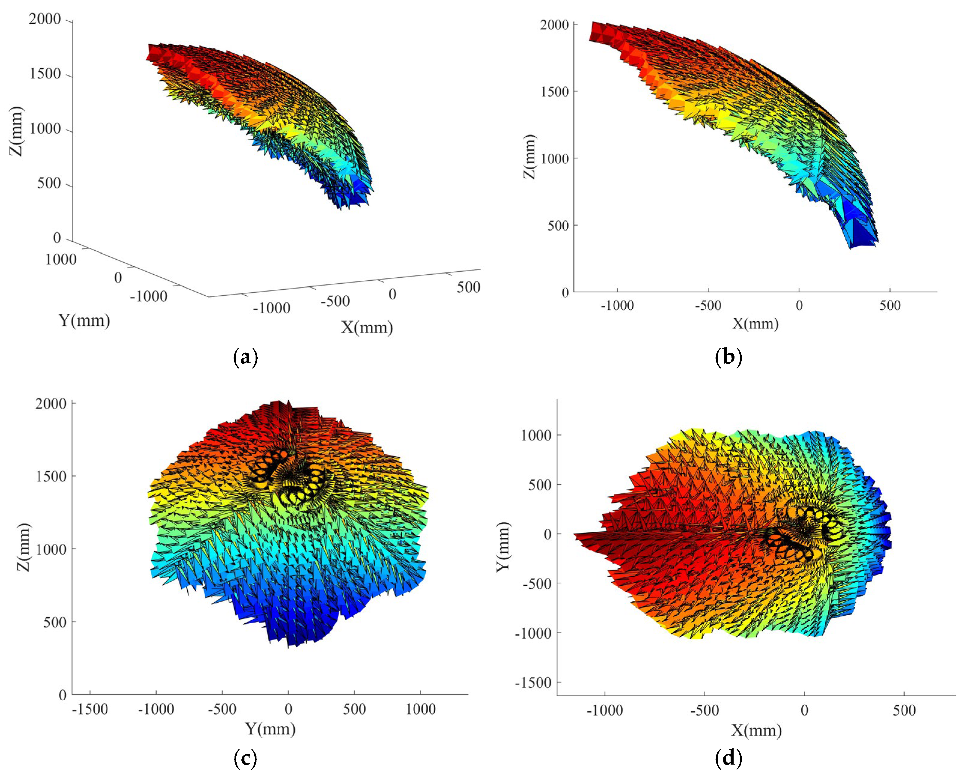
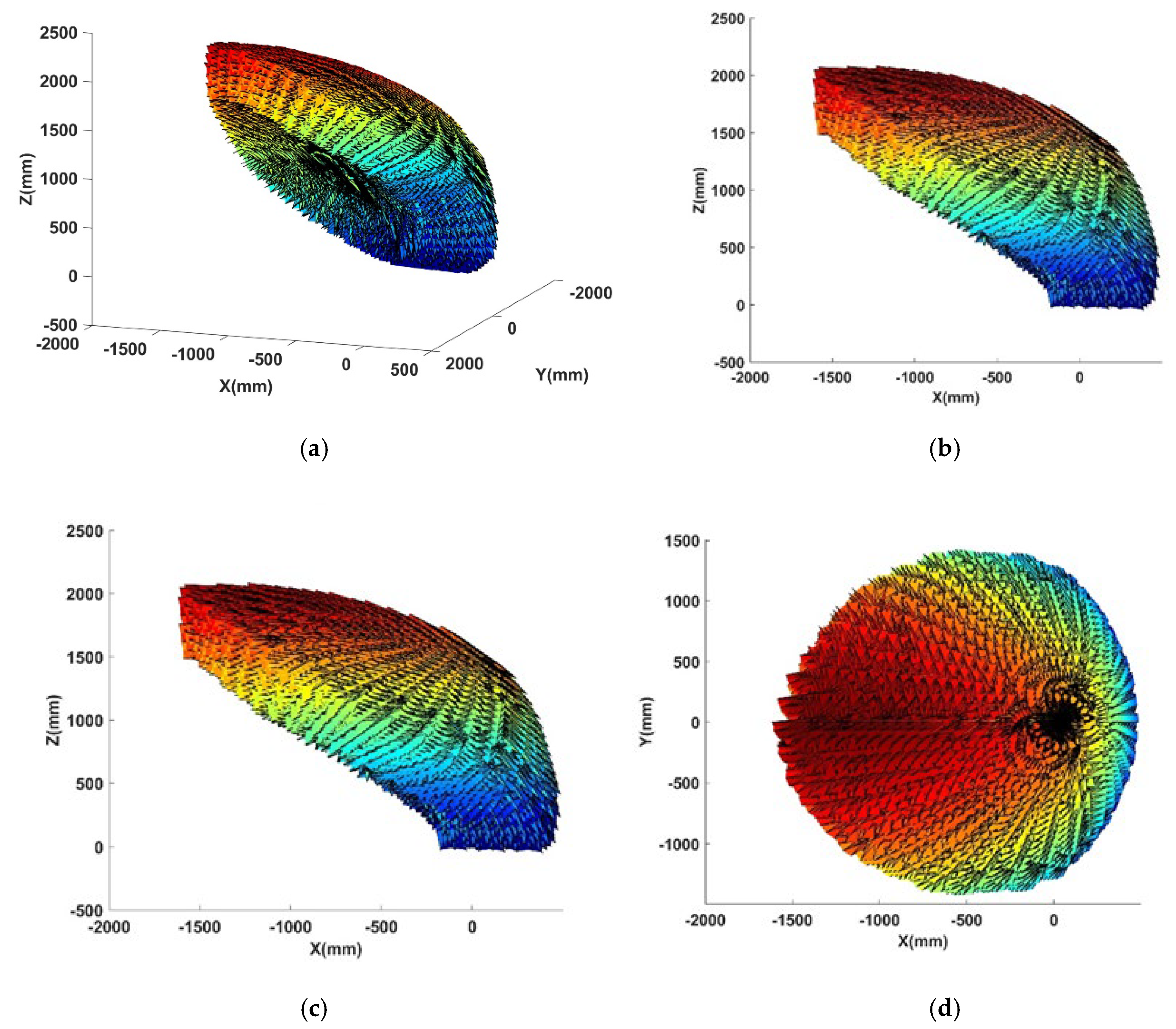
The LOMP robot inclined architecture results in a workspace symmetry axis that deviates from the horizontal plane. Additionally, structural integration requirements dictate a minimum moving platform radius of 140 mm to house the central transmission assembly for the primary rotary head while maintaining adequate installation clearances. Based on design experience, the initial parameters for analysis were set as follows: the expansion range of the active limbs was set to 1200~1680 mm, the radius of the moving platform was 160 mm, the radius ratio of the moving and fixed platforms was 0.45, θ i max   was π/4, and θ i max was π/6. Numerical simulation in MATLAB yields the effective workspace of the processing system, as shown in Figure 2.
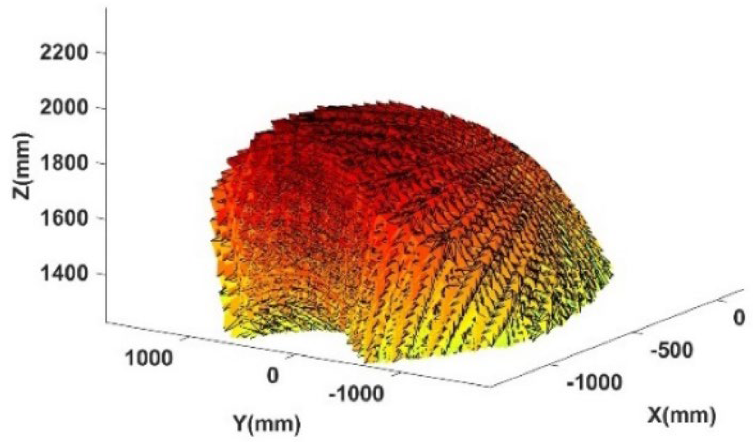
The empirical characterization of the LOMP robot’s effective workspace, as illustrated in Figure 3, demonstrates a unique bowl-type morphology with dual-curvature geometry-featuring convex peripheral boundaries transitioning to concave central regions. In the context of LOMP, it is critical to avoid void regions within the workspace to ensure uninterrupted and stable operation. Furthermore, whenever the workspace allows, the material removal process should be positioned near the concave region. This strategy is based on the observation that when the end-effector operates close to this concave zone, the active kinematic chains attain relatively shorter lengths. Under such configurations, the robot exhibits higher structural stiffness, increased load capacity, and enhanced operational adaptability. These characteristics collectively contribute to improved stability and machining accuracy within the high-performance workspace region. Further analysis of the three views of the workspace shows that when a plane parallel to the XOY plane intersects with the workspace in the XOZ view, the XOY cross-sectional area of the workspace is the largest at Z = 1270.21 mm. At this point, the value range of X is −638.10~214.41 mm, the value range of Y is −983.55~983.55 mm, and the value range of Z is ≥1270.21 mm. The truncated maximum cross-section measures 852.51 mm in width along the X-axis and 1967.1 mm along the Y-axis, which is insufficient to accommodate the required 1200 mm diameter working space for mirror processing. Therefore, the initially designed robotic workspace, based on empirical parameters, fails to meet the operational requirements for LOMP. Further analysis shows that the extracted maximum workspace contains spatial discontinuity, with the apex of the primary void located at coordinates (−594.31, 0, 1594) [units: mm]. This spatial discontinuity further reduces the effective workspace, rendering it inadequate for LOMP requirements. Conventional trial-and-error parameter tuning methods, while capable of achieving the target workspace through empirical adjustments, prove inefficient and ineffective for multi-objective optimization scenarios, failing to guarantee globally optimal parameter configurations for the LOMP robot.
Therefore, it is necessary to employ machine learning algorithms to optimize the workspace of LOMP robots. If the optimization design process focuses only on maximizing the effective workspace as the objective function, the resulting solution will inevitably yield the theoretically largest possible workspace under the given constraints—often at the expense of inefficient space utilization. To address this limitation, this study introduces minimal actuation force as a secondary constraint, thereby deriving an optimized configuration that simultaneously satisfies both the material removal volume requirements for LOMP and the optimal force transmission characteristics.

3.2. Analysis of Actuation Torque

To determine the driving forces of the active limbs, a static analysis of each joint in the parallel mechanism must be performed. Due to the force coupling relationships among the limbs of the parallel robot, the bar-linkage decomposition method is first employed to analyze joint forces. Subsequently, the established equilibrium equations are solved to determine both the magnitude and direction of the unknown forces, ultimately yielding the driving forces of the active limbs.
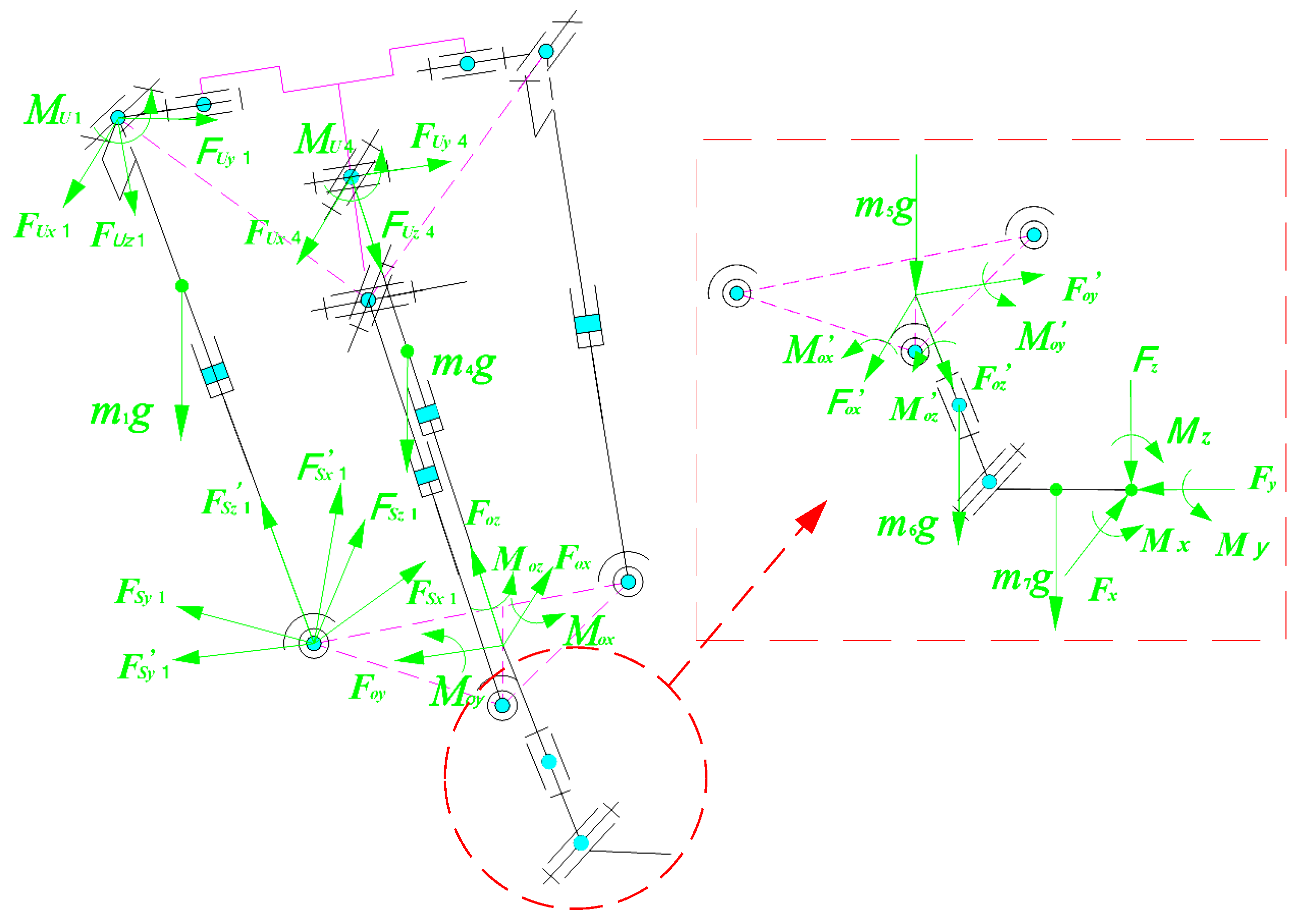
The force analysis diagram of the LOMP robot is shown in Figure 4. The self-weight of UPS drive branch i is mig. The universal joint connected to the fixed platform with two rotational DoFs has three constraint reaction forces and one constraint moment, specifically F U i = [ F U x i ,   F U y i ,   F U z i ] and M U i = [ 0 ,   0 ,   M U z i ] , respectively. The 3-DoF spherical hinge connected to the moving platform has three constraint reactions, which can be expressed as F S i = [ F S x i ,   F S y i ,   F S z i ] .
When the UPS active limb i is in equilibrium, the force balance equation can be expressed as
F U i + F S i + m i G = 0
where G = [ 0 ,   0 ,   g ] .
The constraint reaction force between the moving platform and the spherical joint is represented as F s i = [ F s i x ,   F s i y ,   F s i z ] in the coordinate system Ai-xiyizi, where F s i = R O A i F s i . The torque equilibrium equation can be expressed as follows when performing torque analysis on the UPS limb with point Ai as the origin:
l i × F s i + l c i × m i G + M U i = 0
where l i = [ l x i ,   l y i ,   l z i ] T is the direction vector of the UPS limbs, l i = R O A i l i , l c i = [ l c x i ,   l c y i ,   l c z i ] T is the centroid coordinate of the UPS limbs, and l c i = R O A i l c i , M U i = R O A i M U i .
When the UP limb is in equilibrium, the UP limb is subjected to its gravity m4g, and the universal joints connected to the fixed platform are subjected to a constraint reaction force and three constraint moments, F U 4 = [ F U x 4 ,   F U y 4 ,   F U z 4 ] and M U 4 = [ 0 ,   0 ,   M U z 4 ] , respectively. The fixed connection point with the fixed platform is subjected to three constraint reactions and three constraint moments, F o = [ F o x ,   F o y ,   F o z ] and M o = [ M o x ,   M o y ,   M o z ] , respectively. The force balance equation and torque balance equation of the UP constrained limb are
F U 4 + F o + m 4 G = 0
l 4 × F o + l c 4 × m 4 G + M U 4 + M o = 0
where l 4 = [ l x 4 ,   l y 4 ,   l z 4 ] T is the direction vector of the UP limb, l 4 = R O o l 4 , l c 4 = [ l c x 4 ,   l c y 4 ,   l c z 4 ] T is the centroid coordinate of the UP limb, and l c 4 = R O o l c 4 , M U 4 = R O o M U 4 , and M o = R O o M o .
When the moving platform is in equilibrium, the external forces acting on it include the gravity of the moving platform itself m5g, the gravity of the first-level rotating head m6g, and the gravity of the second-level rotating head m7g, and the constraint reaction force of the UPS limbs are F S i = [ F S x i ,   F S y i ,   F S z i ] , the constraint reaction force and reaction moment of the UP limb are F o = [ F o x ,   F o y ,   F o z ] and M o = [ M o x ,   M o y ,   M o z ] , respectively. The external force and moment acting on the end rotation head connection point of the secondary rotation head are F = [ F x ,   F y ,   F z ] and M = [ M x ,   M y ,   M z ] , respectively. Therefore, the force equilibrium equation and moment equilibrium equation for the moving platform are
F o i = 1 3 F s i + F + ( m 5 + m 6 + m 7 ) G = 0
M o + M + i = 1 3 r F s i + l F × F + l c 6 × m 6 G + l c 7 × m 7 G = 0
where l c 6 = [ l c x 6 ,   l c y 6 ,   l c z 6 ] T are the coordinates of the primary rotation head’s center of mass in the moving platform coordinate system o-xyz, and l c 6 = R O o l c 6 ; l c 7 = [ l c x 7 ,   l c y 7 ,   l c z 7 ] T is the coordinate of the second level rotating head center of mass in the o-xyz, and l c 7 = R O o l c 7 ; l F = [ l F x ,   l F y ,   l F z ] T is the coordinate of the execution point at the end of the second level rotary head in the o-xyz, and l F = R O o l F .
Since this robotic configuration is statically determinate, combining Equations (9) and (14) yields a solvable system of equilibrium equations, from which the unknown joint forces and moments can be determined. The driving forces of the active limbs are given by
τ i = S i F s i + m i S i G
where Si is the unit vector of the active limbs.
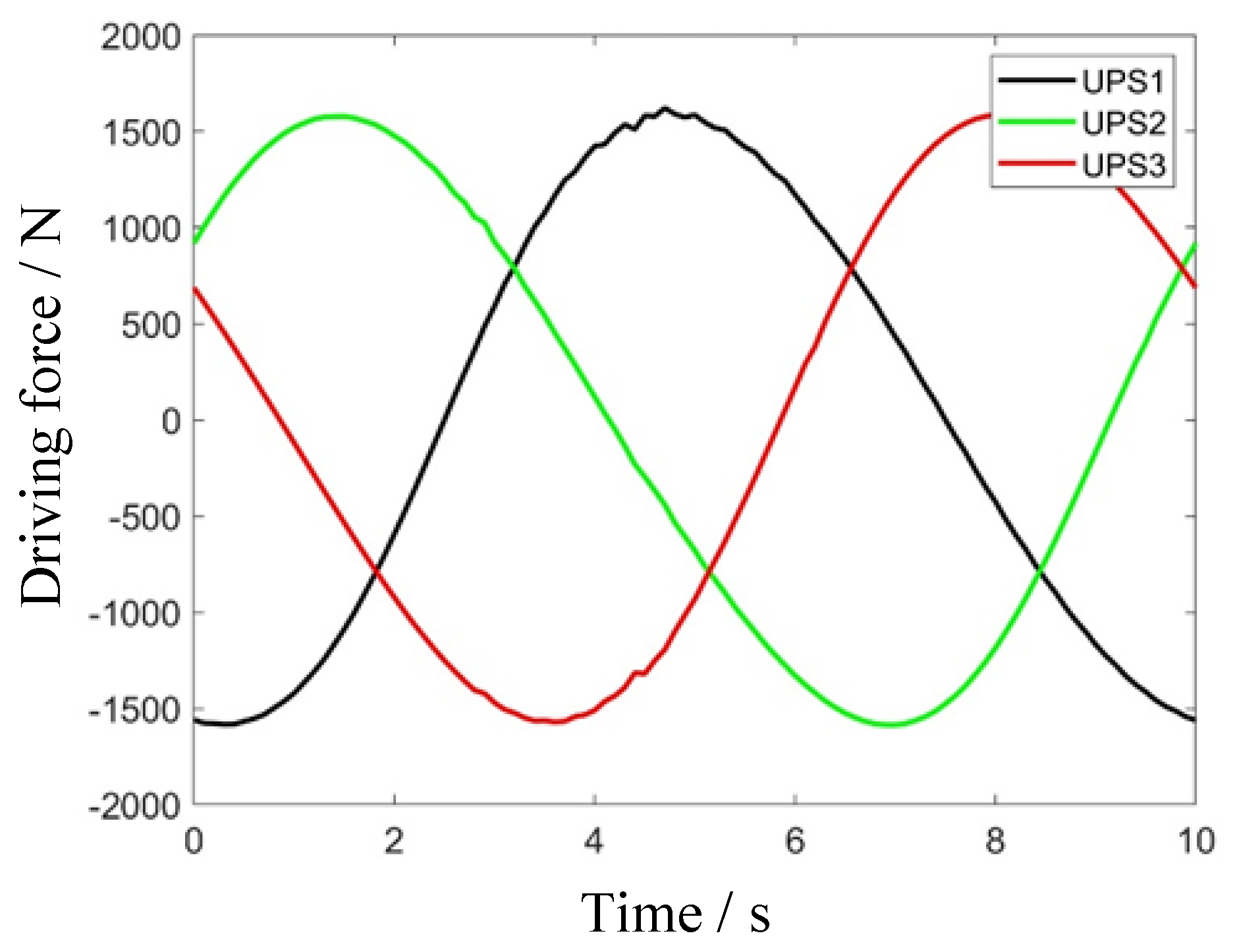
In view of the slow motion and small displacements of the serial module in the 5-DOF hybrid robot, its dynamic effects can be neglected. Therefore, a quasi-static analysis is adopted for the analysis of this module in the simulation. When defining a circular arc trajectory in 3D space as the end-effector’s prescribed path, dynamic simulation analyzes the driving forces of three active limbs in the parallel mechanism. The parametric equations describing the moving platform’s trajectory in the base coordinate frame are
X = 400 cos 2 π t Y = 400 sin 2 π t Z = 1200 0 t
The simulation results of the driving forces are shown in Figure 5. Due to the symmetric arrangement of the three active branch chains and the circular nature of the prescribed spatial trajectory, the driving forces in all three chains exhibit a sinusoidal variation pattern over the motion cycle, with their maximum values being approximately equal. This indicates that both the load and inertial forces are evenly distributed among the three driving chains, which helps mitigate the risk of localized overheating and premature failure caused by excessive loading on any single chain. Furthermore, the balanced force distribution implies that in the presence of tracking errors or external impacts, the resulting disturbances can be uniformly absorbed by all three branches, thereby enhancing the robot’s robustness and control stability.

4. Adaptive Differential Evolution Algorithm

The differential evolution algorithm demonstrates strong robustness in solving nonlinear functions, multi-objective parameter optimization, and complex spatial domain searches. The algorithm primarily consists of mutation, crossover, and selection operations.
(1)
Initial population generation
Randomly initialize a population with Np individuals x n ( 0 ) (n = 1, 2, …, Np) and set the iteration algebra t to 0.
x n ( 0 ) = x min + rand (   ) D × 1 ( x max x min )
where x max is the upper limit of the search range, x min is the lower limit of the search range, D is the dimension of the decision variable, rand (   ) D × 1 generates a random number of 0–1, is the point-to-point multiplication operator, and Np is the population size.
(2)
Individual evaluation
The initialized population is evaluated by calculating the fitness function value f ( x n ( 0 ) ) for each individual, thereby identifying the initial population’s optimal individual x b e s t ( 0 ) .
(3)
Variation
Individuals are selected from the parent population for mutation operations, generating new offspring while preserving parental genetic information.
v n ( t + 1 ) = x b e s t ( t ) + F D E x r 1 ( t ) x r 2 ( t ) + F D E x r 3 ( t ) x r 4 ( t )
where v n ( t + 1 ) is the n-th individual of the t + 1-th generation, x b e s t ( t ) is the optimal individual of the t-th generation, F D E is the mutation operator, and r1~r4 are random numbers of individuals that are not equal to each other.
(4)
Crossover
A random natural number jr is generated within [1, D]. Perform a crossover operation on x n ( t ) and v n ( t + 1 ) to generate experimental individual u n ( t + 1 ) , where the j-th dimensional component is
u n , j ( t + 1 ) = v n , j ( t + 1 ) ,   if   rand C R   or   j = j r x n , j ( t ) ,   else
where x n , j ( t ) and v n , j ( t + 1 ) represent the parent individuals for crossover, CR is the crossover probability, and j r ensures that at least one individual performs crossover operations.
(5)
Choose
Optimize the selection of individuals from the previous generation, retain those with good fitness as the parents of the next generation, and eliminate those with poor fitness. The specific steps are as follows:
x n ( t + 1 ) = u n ( t + 1 ) ,   if   f ( u n ( t + 1 ) ) f ( x n ( t ) ) x n ( t ) ,   else
(6)
Adaptive factor
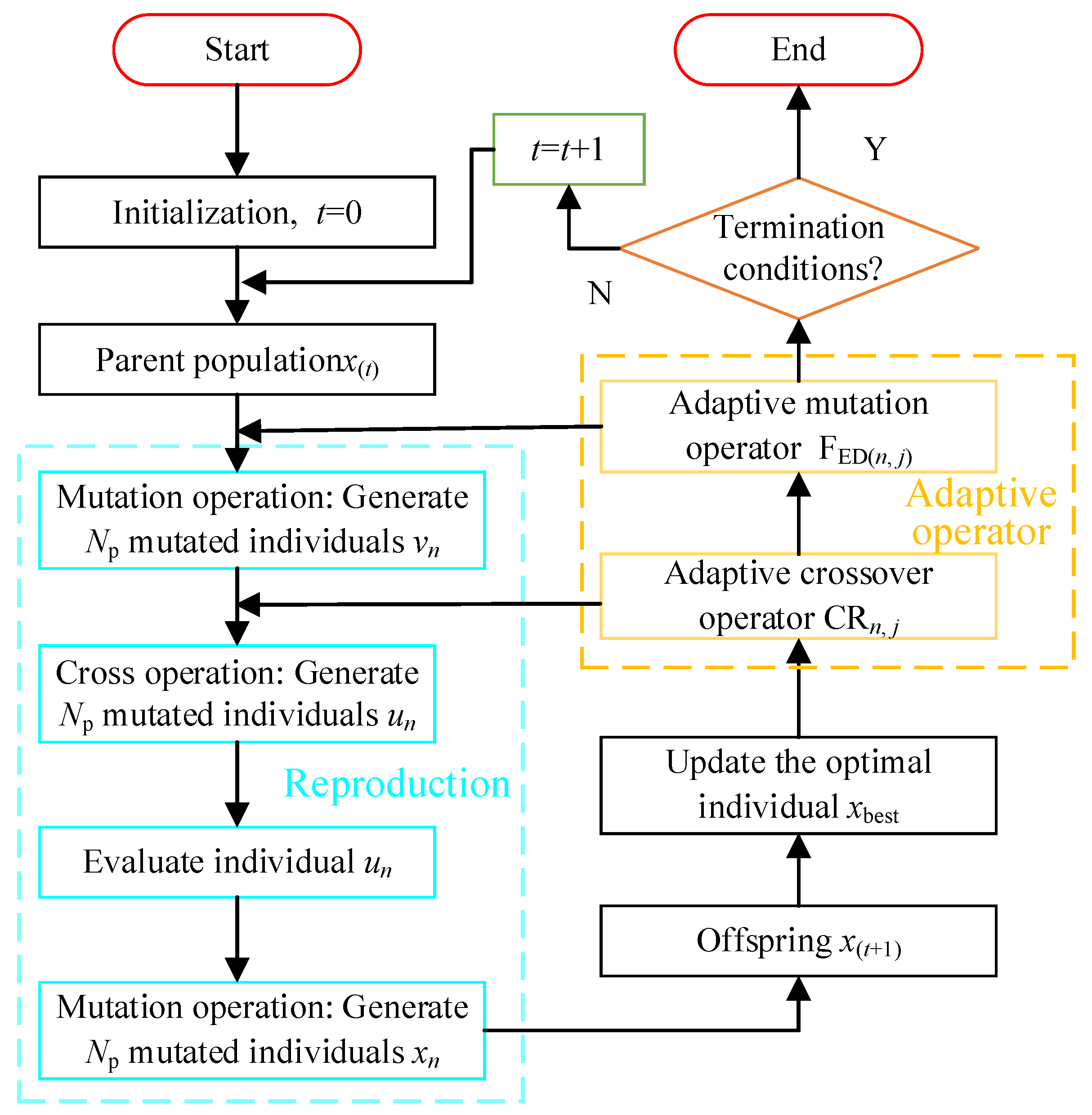
During differential evolution execution, both the mutation factor FED and crossover probability CR critically influence the algorithm’s search capability. To enhance their adaptability, a nonlinear evaluation method is employed to dynamically select optimal FED and CR values. The nonlinear evaluation strategy is defined as follows:
S n , j = 0.5 + 0.5 f a v f n , j f a v f min , f n , j < f a v 0.5 f max f n , j f max f a v , e l s e
where S n , j is the optimization operator, and f min , f max , and f a v are the minimum, maximum, and average values of fitness, respectively. The adaptive mutation operator and crossover operator that introduce optimization operators can be expressed as
F E D ( n , j ) = F max S n , j ( F E D ( max ) F E D ( min ) )
C R n , j = C R max S n , j C R max C R min
where F E D ( n , j ) and C R n , j are adaptive mutation and crossover operators, F E D ( max ) and F E D ( min ) represent the upper and lower limits of the mutation operator, and C R max and C R min represent the upper and lower limits of the crossover operator.
The ADEA implementation procedure is shown in Figure 6.

5. Scale Parameter Optimization

Scale parameter optimization using ADEA requires constructing a multi-objective optimization function for the robotic system, incorporating parameters of the moving platform, dynamic platform, and active limbs.
max   W s e = f ( l i ,   r ,   r / R ,   F l i ,   Z min , R k )
where F l i is the driving force of the active branch chain i.
For this optimization function, l i , r , r / R , and F l i are decision variables and Z min and R k are constraints. The optimization design sets the following parameters: a minimum workspace height of 200 mm in the Zmin direction, an active limb length search range of 800–1400 mm with 10 mm increments, a ball screw stroke range of 400–1000 mm (10 mm steps), a moving platform radius range of 140–200 mm (5 mm steps), a moving-to-fixed platform ratio of 0.2–0.5 (0.01 step size), and Rk ≥ 625 mm.
It is important to note that while meeting the basic workspace requirements, it is generally desirable to incorporate a certain degree of redundant workspace to accommodate uncertainties and complexities in the processing environment. However, the introduction of such redundancy may lead to an increase in the required driving force due to the influence of the robot’s structural parameters, with a nonlinear functional relationship existing between the workspace and the driving force. Accordingly, a metric that balances workspace expansion and driving force is established to optimize the redundant workspace, ensuring that it satisfies operational requirements without excessively increasing the driving force.
k τ = R k / R k ( min ) F l i m / F l i ( max )
where k τ is the scaling factor, R k is the current effective space radius, R k ( min ) represents the minimum effective workspace radius, F i m is the minimum driving force of the three active limbs under the current effective space, and F i ( max ) is the maximum driving force of the three active limbs under the minimum effective space. Since the three UPS limbs of the parallel robot share identical configurations, the same brand and model of servo motors are uniformly adopted to ensure consistent electrical performance across all UPS limbs. Consequently, the optimal driving force is determined by the maximum force among all limbs.
Based on the above analysis, the optimization objectives for the LOMP robot’s workspace are redefined as achieving a base radius greater than 650 mm while minimizing driving forces, with Figure 7 showing the globally optimized workspace using ADEA, Figure 8 displaying the manually truncated subspace, and Figure 9 presenting the maximum effective workspace obtained through the ADEA.
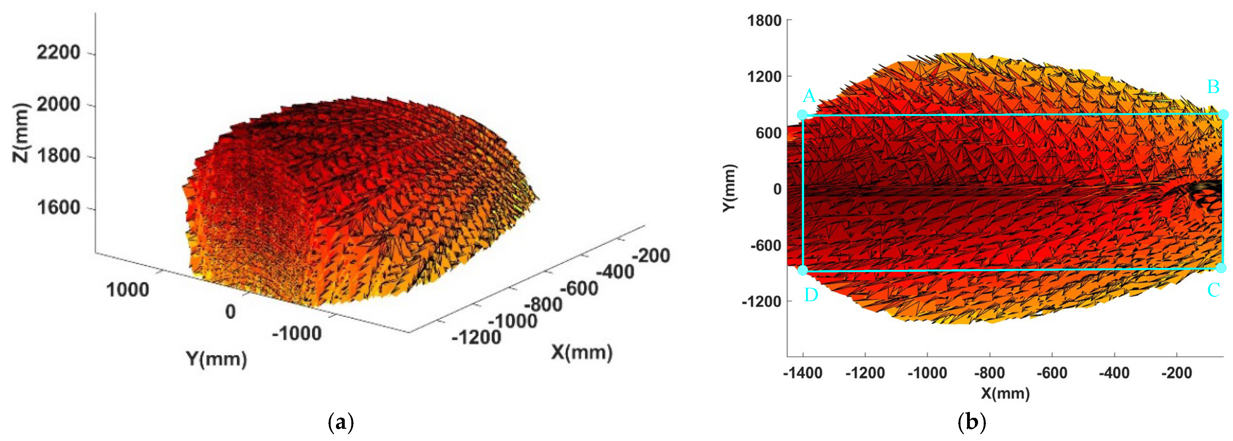
The results of multi-objective scale parameter optimization for the workspace of the LOMP robot using the ADEA are shown in Figure 7. As shown in the 3D plot of Figure 7a, the workspace appears as a solid, spheroid-like space. From the XOY view in Figure 7b, a maximum inscribed circle can be constructed within the rectangle formed by points A (−1395, 789), B (−25, 789), C (−25, −789), and D (−1395, −789), representing the base of the maximum effective workspace. Based on the coordinates of these four vertices, the diameter of the maximum effective workspace base is 1370 mm, which meets the processing requirements for optical mirrors with a diameter of 1250 mm. As shown in Figure 8, the effective workspace obtained from the maximum cross-section of the XOZ view using the empirical method is compared with the optimal effective workspace derived from the ADEA. The result from the ADEA successfully avoids the void regions within the workspace, thus achieving a more accurate and truly maximal effective workspace.
The optimized global workspace is presented in Figure 9. Compared to the results from the empirical method, the optimized configuration maintains sufficient redundant workspace even after removing areas with a bottom diameter of 1370 mm and Z min is 200 mm.
The scale parameters (rounded) of the LOMP robot obtained by the ADEA are shown in Table 1, with the optimized active climbs stroke range of 950–1750 mm, a moving platform radius of 150 mm, a moving/fixed platform radius ratio of 0.375, and a maximum effective workspace base radius of 685 mm.
Further analysis of Table 1 reveals that the optimized workspace, while simultaneously satisfying both processing requirements and minimum driving force criteria, exhibits a vertical (Z-axis) height range of 200 mm (minimum) to 616.82 mm (maximum). This configuration not only fulfills LOMP specifications but also ensures adequate kinematic redundancy in the robotic processing system.
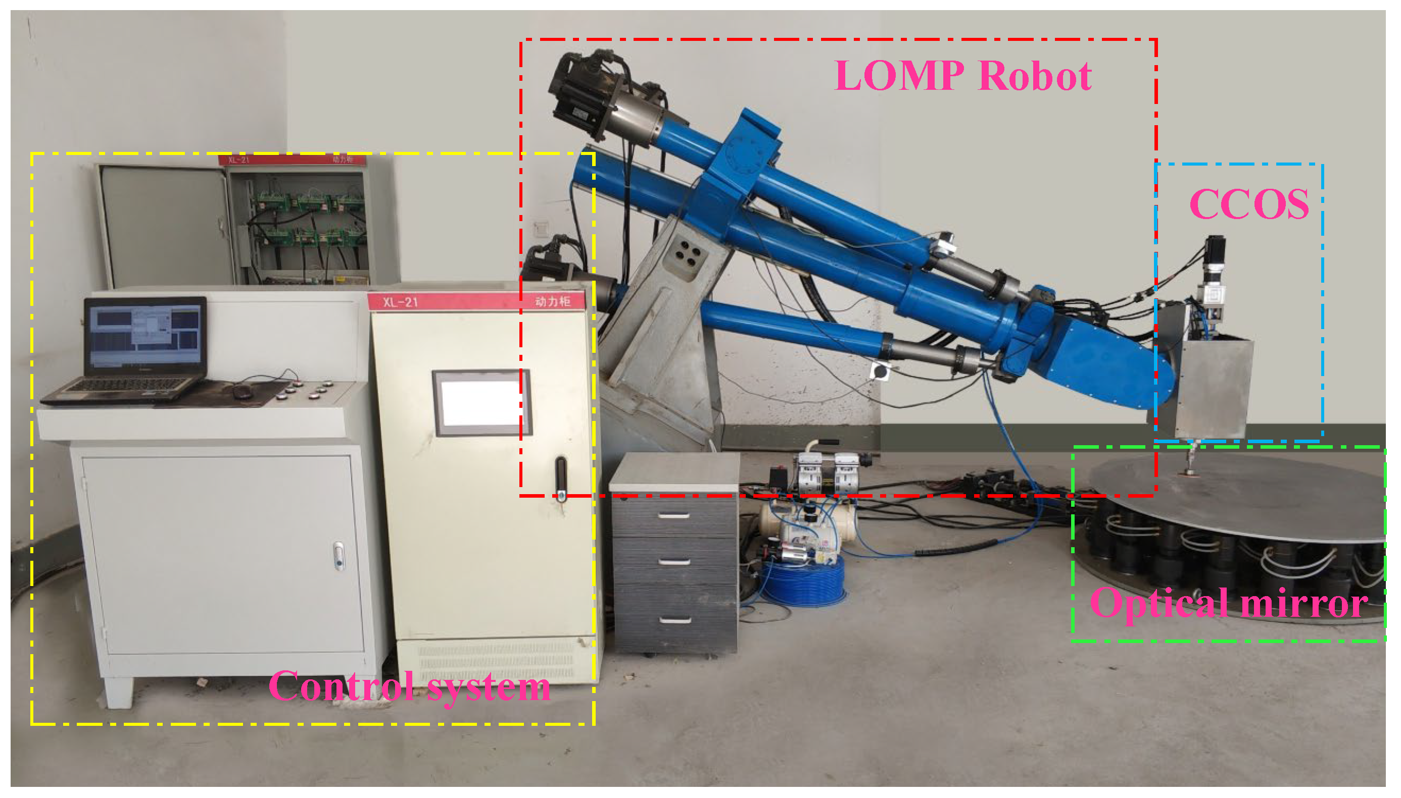
An engineering prototype of the LOMP robot was fabricated based on the scale parameters obtained from the optimized design (as shown in Figure 10), and the measurement results of the actual workspace are shown in Table 2. Experimental tests conducted on the prototype revealed that its actual workspace matched the optimized simulation results, thereby validating the effectiveness of the design optimization method and the accuracy of the experimental findings.

6. Discussion

This study proposes an ADEA for the multi-objective optimization of optical mirror scale parameters. The algorithm successfully balances the nonlinear relationship between workspace and driving force and identifies an optimal parameter set that meets the optical processing requirements. However, the validation of the kinematic and dynamic models relies on idealized assumptions, which limits their practical applicability. Therefore, several challenges must be addressed before the findings can be applied to real engineering contexts.
(1) This optimization model uses the workspace and driving forces under quasi-static conditions as its objective functions and does not incorporate dynamic performance indicators such as end-effector tracking error or vibration modes. During actual mirror processing, the robotic system may be subject to dynamic influences, including vibrations from the machine body, force disturbances caused by the interaction between the polishing tool and the workpiece, as well as inertial forces due to motion acceleration. These dynamic effects directly affect the stability of the machining process and the final surface accuracy. The optimization results presented in this paper constitute an “open-loop” solution in terms of dynamic robustness, and their superiority requires further validation within closed-loop control systems and under explicit dynamic disturbance scenarios. Future work will focus on formulating optimization objectives that include key dynamic indicators and investigating compensation strategies based on disturbance observers or robust control.
(2) The optimal scale parameters derived in this study are theoretical values. However, in practical manufacturing and assembly processes, deviations at the micron or even millimeter level are inevitable in parameters such as link lengths, joint clearances, and motor mounting positions. These tolerances accumulate and amplify through the kinematic chain of the robotic mechanism, ultimately leading to reduced positioning accuracy of the end-effector. In future work, to address this issue, the engineering prototype will be calibrated, and an accurate error propagation model will be established. This will allow the identification of the optimal workspace and driving forces in the physical prototype, enabling comparison with the theoretical model and improving the accuracy of the model-based theoretical analysis.
(3) The optimization process in this study implicitly assumes an ideal error-free tracking controller. However, real-world control systems are subject to issues such as time delays, modeling errors, inaccurate parameter identification, and insufficient friction compensation. These control uncertainties lead to discrepancies between the actual and commanded outputs at each joint. In future work, incorporating model uncertainties in the control loop as an optimization constraint or objective through control–structure co-design represents an effective approach to achieving higher-performance mirror machining robots.
In summary, the method proposed in this paper provides an efficient theoretical optimization tool and a clear perspective on performance trade-offs for the conceptual design of LOMP robots. However, to translate these results into a high-precision and high-stability physical prototype, further in-depth and systematic research addressing the aforementioned issues remains essential.

7. Conclusions

The workspace of LOMP robots is constrained by multi-objective scale parameters, including moving platform radius, fixed/moving platform radius ratio, and limb length. While empirical manual optimization can yield scale parameters that satisfy the optical mirror removal workspace requirements, it often fails to achieve the optimal set of parameters for a robotic system. This study employs an ADEA to optimize the dimensional parameters of a LOMP robot, aiming to achieve an optimal workspace for mirror surface processing. Subsequently, adaptive mutation and crossover operators are introduced into the differential evolution algorithm, forming an ADEA to enhance the convergence speed of the optimization process. Finally, MATLAB simulation results demonstrate that the proposed ADEA can obtain precise optimal scale parameter combinations while satisfying all constraints. The optimized dimensional parameters include a 950–1750 mm stroke range for the three active kinematic chains, a 150 mm radius moving platform with a 0.375 moving-to-base platform ratio, and a 685 mm maximum effective workspace base radius. While meeting LOMP requirements, the robotic system maintains adequate motion redundancy.
Therefore, the application of ADEA to the dimensional optimization of a 5-DOF hybrid robot demonstrates significant advantages in convergence speed, global search capability, and robustness. Compared to conventional empirical approaches, the proposed method proves to be more efficient and labor-saving, while yielding dimensional parameters that better align with operational requirements. The findings of this study provide a theoretical foundation for the multi-objective optimization of dimensional and structural parameters in parallel and hybrid robotic systems and also offer a theoretical basis for the integrated optimization of multi-robot cooperative equipment.

Author Contributions

Conceptualization, Z.J.; methodology, Z.Y.; software, Z.J.; validation, Z.J. and H.G.; formal analysis, Z.J.; investigation, H.L.; resources, Z.J. and Z.Y.; data curation, H.L.; writing—original draft preparation, Z.J.; writing—review and editing, Z.Y.; visualization, H.L.; supervision, Z.Y.; project administration, Z.Y.; funding acquisition, Z.J., H.L., H.G. and Z.Y. All authors have read and agreed to the published version of the manuscript.

Funding

This research was funded by the Doctoral Scientific Research Foundation of Suzhou University, grant number 2023BSK016 (Z.J.); the Key Project of Natural Science Research in Universities of Anhui Province, grant numbers 2023AH052237 (H.L.) and 2024AH051812 (Z.J.); the Excellent Scientific Research and Innovation Teams in Anhui Province’s Universities, grant number 2023AH010055 (Z.J., Z.Y.); the Key Research and Development Program Projects in Anhui Province, grant number 2023t070200 (Z.Y.); the Anhui Province Higher Education Provincial Quality Engineering Project, grant numbers 2023sdxx088 (Z.Y., Z.J.), 2024sx154 (Z.J.), and 2023cyts045 (Z.Y., Z.J.); the Inland Visiting and Research Fellowship Program for Young Key Teachers, grant number JNFX2024063 (Z.Y.); and the Natural Science Research Project in the Universities of Anhui Province, grant number 2023AH053390 (H.G.).

Data Availability Statement

Data are contained within the article.

Conflicts of Interest

The authors declare no conflicts of interest.

References

  1. Jin, Z.J.; Cheng, G.; Guo, F.; Chen, S.B. Human-machine-environment information fusion and control compensation strategy for large optical mirror processing system. Proc. Inst. Mech. Eng. Part C J. Eng. Mech. Eng. Sci. 2020, 35, 2507–2523. [Google Scholar]
  2. Jin, Z.; Yin, Z.; Liu, H.; Liu, F. Dynamic characteristics, analysis, and measurement of a large optical mirror processing system. Machines 2024, 12, 788. [Google Scholar] [CrossRef]
  3. Li, L.X.; Li, X.C.; Cheng, Q.; Li, R.G.; Deng, W.J.; Luo, X.; Zhang, F.; Xue, D.L.; Zhang, X.J. Optimized strategy to restrain the mid-spatial-frequency surface error in computer-controlled optical surfacing. Results Phys. 2021, 19, 103356. [Google Scholar]
  4. Pullen, W.C.; Wang, T.Y.; Choi, H.; Ke, X.L.; Negi, V.S.; Huang, L.; Idir, M.; Kim, D. Statistical tool size study for computer-controlled optical surfacing. Photonics 2023, 10, 286. [Google Scholar] [CrossRef]
  5. Anvari, Z.; Ataei, P.; Masouleh, M.T. Collision-free workspace and kinetostatic performances of a 4-DOF delta parallel robot. J. Braz. Soc. Mech. Sci. Eng. 2019, 41, 99. [Google Scholar] [CrossRef]
  6. Dastjerdi, A.H.; Sheikhi, M.M.; Masouleh, M.T. A complete analytical solution for the dimensional synthesis of 3-DOF delta parallel robot for a prescribed workspace. Mech. Mach. Theory 2020, 153, 103991. [Google Scholar] [CrossRef]
  7. Xiao, Y.G.; Yin, K.; Chen, X.B.; Chen, Z.J.; Gao, F. Multi-objective optimization design method for the dimensions and control parameters of curling hexapod robot based on application performance. Mech. Mach. Theory 2024, 204, 105831. [Google Scholar] [CrossRef]
  8. Panagant, N.; Pholdee, N.; Bureerat, S.; Yildiz, A.R.; Mirjalili, S. A comparative study of recent multi-objective metaheuristics for solving constrained truss optimisation problems. Arch. Comput. Method Eng. 2021, 28, 4031–4047. [Google Scholar] [CrossRef]
  9. Su, C.X.; Li, B.; Zhang, W.; Tian, W.; Liao, W.H. An analysis and reliability-based optimization design method of trajectory accuracy for industrial robots considering parametric uncertainties. Reliab. Eng. Syst. Saf. 2024, 254, 110626. [Google Scholar] [CrossRef]
  10. Cui, Q.Y.; Liu, P.F.; Du, H.L.; Wang, H.; Ma, X. Improved multi-objective artificial bee colony algorithm-based path planning for mobile robots. Front. Neurorobotics 2023, 17, 1196683. [Google Scholar]
  11. Nelson, C.A.; Laribi, M.A.; Zeghloul, S. Multi-robot system optimization based on redundant serial spherical mechanism for robotic minimally invasive surgery. Robotica 2019, 37, 1202–1213. [Google Scholar]
  12. Fang, Y.L.; Li, Z.Y.; Wang, S.W.; Lu, X.W. Multi-objective multi-fidelity optimisation for position-constrained human-robot collaborative disassembly planning. Int. J. Prod. Res. 2023, 62, 3872–3889. [Google Scholar]
  13. Li, C.Y.; Wu, H.P.; Eskelinen, H. Design and multi-objective optimization of a dexterous mobile parallel mechanism for fusion reactor vacuum vessel assembly. IEEE Access 2021, 9, 153796–153810. [Google Scholar] [CrossRef]
  14. Leng, X.K.; Piao, S.H.; Chang, L.; He, Z.C.; Zhu, Z. Parameter design of biped robot motion system based on multi-objective optimization. J. Intell. Fuzzy Syst. 2021, 41, 4307–4318. [Google Scholar] [CrossRef]
  15. Wu, J.; Wang, X.J.; Zhang, B.B.; Huang, T. Multi-objective optimal design of a novel 6-DOF spray-painting robot. Robotica 2021, 39, 2268–2282. [Google Scholar]
  16. Yan, L.; Xu, W.F.; Hu, Z.H.; Liang, B. Multi-objective configuration optimization for coordinated capture of dual-arm space robot. Acta Astronaut. 2020, 167, 189–200. [Google Scholar]
  17. Liang, X.; Zeng, X.; Li, G.T.; Chen, W.T.; Su, T.T.; He, G.P. Design, analysis, and optimization of a kinematically redundant parallel robot. Actuators 2023, 12, 120. [Google Scholar] [CrossRef]
  18. Wang, H.; Du, Z.J.; Yan, Z.Y.; Gao, Y.Z. Genetic algorithm-based optimal design strategy of a continuum surgical manipulator. Int. J. Control Autom. Syst. 2022, 20, 3312–3320. [Google Scholar]
  19. Lan, J.Y.; Xie, Y.G.; Liu, G.J.; Cao, M.X. A multi-objective trajectory planning method for collaborative robot. Electronics 2020, 9, 859. [Google Scholar] [CrossRef]
  20. Zhou, B.; Li, S.P.; Zi, B.; Chen, B.; Zhu, W.D. Multi-objective optimal design of a cable-driven parallel robot based on an adaptive adjustment inertia weight particle swarm optimization algorithm. J. Mech. Des. 2023, 145, 083301. [Google Scholar]
  21. Gul, F.; Rahiman, W.; Alhady, S.S.N.; Ahmad, A.; Mir, I.; Jalil, A. Meta-heuristic approach for solving multi-objective path planning for autonomous guided robot using PSO-GWO optimization algorithm with evolutionary programming. J. Ambient Intell. Humaniz. Comput. 2021, 12, 7873–7890. [Google Scholar] [CrossRef]
  22. Maafi, R.A.; Haghighi, S.E.; Mahmoodabadi, M.J. Pareto optimal design of a fuzzy adaptive sliding mode controller for a three-link model of a biped robot via the multi-objective improved team game algorithm. J. Braz. Soc. Mech. Sci. Eng. 2022, 44, 428. [Google Scholar] [CrossRef]
  23. Wu, D.; Hou, G.W.; Qiu, W.J.; Xie, B. T-IK: An efficient multi-objective evolutionary algorithm for analytical inverse kinematics of redundant manipulator. IEEE Robot. Autom. Lett. 2021, 6, 8474–8481. [Google Scholar] [CrossRef]
  24. Wu, M.L.; Zhang, Y.; Yue, X.Q.; Lv, D.Y.; Chen, M.; Wang, X.H.; Zhang, J. Optimal design of an asymmetrical parallel mechanism. Proc. Inst. Mech. Eng. Part C J. Eng. Mech. Eng. Sci. 2021, 235, 6922–6939. [Google Scholar] [CrossRef]
  25. Benamor, A.; Boukadida, W.; Messaoud, H. Genetic algorithm-based multi-objective design of optimal discrete sliding mode approach for trajectory tracking of nonlinear systems. Proc. Inst. Mech. Eng. Part C J. Eng. Mech. Eng. Sci. 2019, 233, 5237–5252. [Google Scholar] [CrossRef]
  26. Hou, R.L.; Niu, J.W.; Guo, Y.L.; Ren, T.; Yu, X.L.; Han, B.; Ma, Q. A novel resolution scheme of time-energy optimal trajectory for precise acceleration controlled industrial robot using neural networks. Actuators 2022, 11, 130. [Google Scholar] [CrossRef]
  27. Wiedmeyer, W.; Altoé, P.; Auberle, J.; Ledermann, C.; Kröger, T. A real-time-capable closed-form multi-objective redundancy resolution scheme for seven-DOF serial manipulators. IEEE Robot. Autom. Lett. 2021, 6, 431–438. [Google Scholar] [CrossRef]
  28. Huo, X.M.; Lian, B.B.; Wang, P.F.; Song, Y.M.; Sun, T. Topology and dimension synchronous optimization of 1T2R parallel robots. Mech. Mach. Theory 2023, 178, 105385. [Google Scholar] [CrossRef]
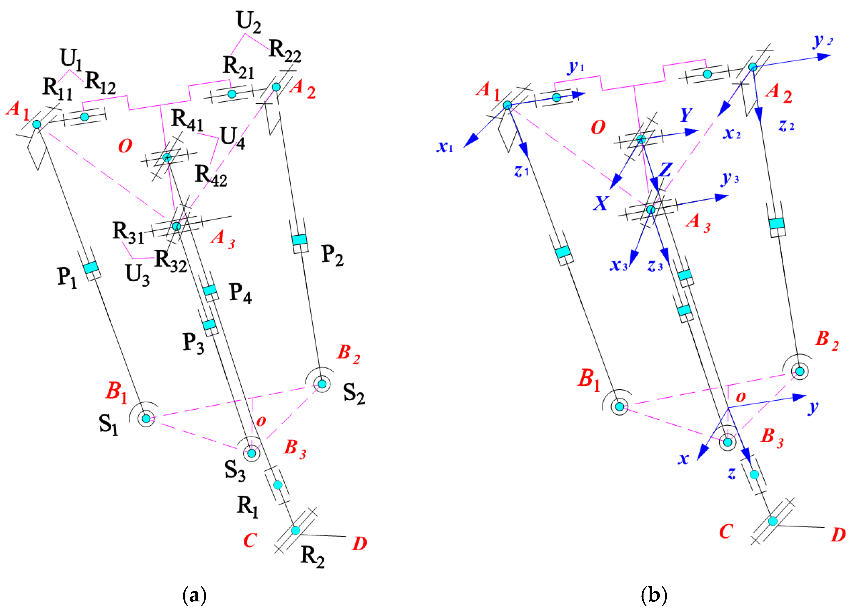
Figure 1. LOMP robot. (a) Topological structure diagram. (b) Coordinate system diagram.
Machines 13 00853 g001
Figure 2. The workspace under empirical parameters. (a) 3D view. (b) XOZ view. (c) YOZ view. (d) XOZ view.
Machines 13 00853 g002
Figure 3. Maximum effective workspace under empirical parameters.
Machines 13 00853 g003
Figure 4. Force analysis of the LOMP robot.
Machines 13 00853 g004
Figure 5. Active limb driving force of the LOMP robot.
Machines 13 00853 g005
Figure 6. Flowchart of the ADEA.
Machines 13 00853 g006
Figure 7. Optimized design results. (a) 3D view. (b) XOY view.
Machines 13 00853 g007
Figure 8. Void regions identified at the maximal cross-section.
Machines 13 00853 g008
Figure 9. Optimized global workspace. (a) 3D view of the workspace. (b) XOZ view of the workspace. (c) YOZ view of the workspace. (d) XOY view of the workspace.
Machines 13 00853 g009
Figure 10. Prototype of LOMP robot.
Machines 13 00853 g010
Table 1. Scale parameters for optimal effective workspace.
Parametersli/mmr/mmr/RRk/mmZmin/mmZmax/mm
Values950~17501500.375685200616.82
Table 2. Measured values of scale parameters and workspace of experimental prototype.
Parametersli/mmr/mmr/RRk/mmZmin/mmZmax/mm
Values950.25~1748.51150.020.376684.38198.57615.21
Disclaimer/Publisher’s Note: The statements, opinions and data contained in all publications are solely those of the individual author(s) and contributor(s) and not of MDPI and/or the editor(s). MDPI and/or the editor(s) disclaim responsibility for any injury to people or property resulting from any ideas, methods, instructions or products referred to in the content.