1. Introduction
Gears, with their diverse transmission forms, excellent load-bearing capacity, and high output efficiency, hold a pivotal position in various mechanical transmission systems. The significance of their reliability and high-precision performance is self-evident, which has been thoroughly verified by numerous studies [
1,
2,
3]. However, as modern industrial demands for gear operating conditions become increasingly stringent, the issues of gear interface lubrication and meshing load-bearing have gradually come to the fore, becoming key research topics that attract widespread attention [
4,
5,
6]. Particularly for gear transmission systems operating under Thermo-Elastic Hydrodynamic Lubrication (TEHL) mode in extreme environments such as deep-sea, polar, and ultra-low temperature applications, unprecedented challenges are encountered. In the rolling/sliding line contact transmission process, potential fault risks cannot be overlooked [
7,
8,
9]. Among them, anti-scuffing load-bearing fatigue is one of the most common failure modes of the meshing interface, and its failure characteristics are mainly manifested in local spalling and micropitting and other surface damage forms [
10,
11,
12]. This failure mechanism will significantly impact on the reliability and service life of transmission systems. When the thickness of the interlayer film between the sliding contact interfaces is sufficient, it can effectively prevent the occurrence of scratches, abrasions, and frictional wear to a certain extent. However, the micro-pitting of the meshing interface, as a typical characteristic of early fatigue failure, is still difficult to eliminate completely. This kind of damage often undergoes a progressive development process, evolving from initial pitting to severe spalling, and ultimately may lead to catastrophic tooth breakage failure [
13,
14,
15]. Even under the TEHL mode, this failure mechanism cannot be completely avoided. The fundamental reason is that the main interlayer film can only exert a limited regulatory effect on the cyclic contact stress amplitude of the meshing interface, but it cannot fundamentally eliminate the stress concentration effect. Even if the lubrication time is extended, it is still difficult to completely prevent the initiation and development of such damage. Insufficient lubrication of the gear pair will lead to a significant increase in interfacial friction force/torque, thereby adversely affecting its dynamic contact load-bearing performance [
16]. The key scientific issues regarding the synergistic mechanism of interface microelement lubrication regulation and texture load-bearing remain to be resolved [
17], and the proposed correlation models have not yet reached a unified consensus. Surface roughness plays a crucial role in most tribological pairs, and gears are no exception, whether lubricated or not. This is especially true for the initiation and evolution process of micro-pitting in the meshing interface under the TEHL mode. Although a non-rough meshing interfaces can effectively reduce micro-pitting failures and even avoid contact-induced fatigue as well as adverse effects at the micro-scale, it may shorten the service life of gears, as confirmed by relevant studies [
18,
19,
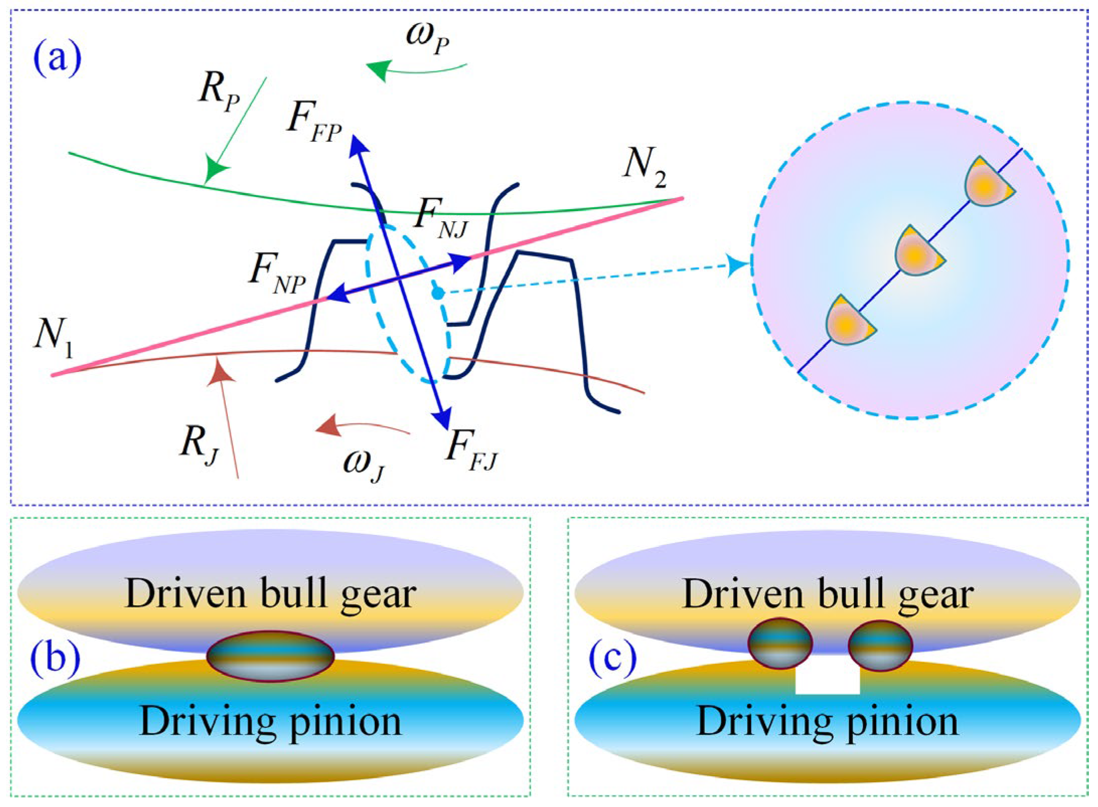
20]. The design of textured micro-elements configurations and the synergistic mechanism between interface lubrication regulation and meshing load-bearing are closely linked to the service performance and operational reliability of gears. These intertwined factors exhibit intricate and complex mapping relationships, as illustrated in
Figure 1, which undoubtedly poses significant challenges to constructing a unified theoretical model that comprehensively considers the micro-elements Interface Enriched Lubrication (IEL) characteristics and meshing Anti-Scuffing Load-Bearing Capacity (ASLBC).
Balancing friction reduction and load-bearing capacity is a crucial task in gear systems; the issue of micro-element-asperity contact of textured interfaces is particularly prominent [
21,
22,
23]. This problem can be further refined into two research directions. First, how to mitigate the failure of micro-element-asperity contact through interface morphology modulation, thereby significantly enhancing the meshing load-bearing durability of the textured interface. Second, how to develop a multi-scale adaptive mechanism for suppressing micro-asperity damage, enabling autonomous restoration of the roughness characteristics of the textured interface. This dual-path research framework not only focuses on proactive prevention of micro-element-asperity contact fatigue failure, but also incorporates dynamic regulation of textured interface damage evolution, offering novel insights for surpassing the performance limits of conventional lubrication and load-bearing approaches. The synergistic mechanism through which lubrication performance governs load-bearing capacity involves multiple complex factors intrinsically linked to gear meshing interfaces. Key influencing parameters include contact stress distribution, frictional thermal effects, and gear surface topography characteristics, which collectively determine both lubrication failure modes and fatigue life performance in gear systems [
24]. Previous studies on the tribological characteristics of meshing interfaces have predominantly been conducted within the framework of ElastoHydrodynamic Lubrication (EHL) theory. Some investigations have incorporated Thermo-Elastic Hydrodynamic Lubrication (TEHL) modified models [
25], particularly when addressing extreme operating conditions involving elevated or cryogenic temperatures. The characteristic features of micro-textured topography significantly affect localized contact stress concentration phenomena and transient flash temperature distribution at the meshing interface by altering the proportion of real contact zone. While conventional mechanical design theory typically considers reducing interface roughness as a standard approach to improving tribological performance, recent advances in biomimetic tribology have demonstrated that functionally designed micro-textured interface elements can achieve superior engineered contact characteristics [
26]. Currently, research on the influence of the mechanism of surface roughness effects has established a relatively comprehensive theoretical system for gear pairs with rolling-sliding composite motion under line contact conditions [
27].
As a research hotspot in the fields of tribological micro-element configuration design and surface finishing of contact interfaces, textured micro-element optimization plays a crucial role in improving tribological performance. Well-designed interface microtextures can effectively reduce the friction coefficient, optimize lubrication conditions, and enhance load-carrying capacity [
28]. Conversely, under sliding line contact friction conditions, meshing interfaces lacking effective textured micro-elements are prone to localized stress concentration and thermal shock phenomena, leading to complex thermo-scuffing lubrication failure issues such as scratches, adhesive wear, and oxidative corrosion [
29,
30,
31]. The introduction of micro-textures can facilitate the formation and transfer of secondary lubrication films between meshing interfaces, significantly enhancing the lubricant enriched effect and prolonging service life, thereby achieving precise regulation of the interfacial lubrication state and stable improvement of load-bearing performance between meshing teeth [
32,
33,
34]. Currently, research on the influence of mechanisms of micro-textures on meshing interfaces remains relatively limited. The latest studies have shown that applying micro-textures with specific parameters (configuration scale: diameter 200–600 μm, depth 50–150 μm) to the lateral side of meshing interfaces can effectively promote the formation of TEHL films and enable efficient capture of wear particles. Experiments confirm that such micro-texture designs can reduce the vibration amplitude of gear transmission systems by up to 51.6%, significantly improving operational stability [
35,
36,
37]. Vertically arranged elliptical micro-element configurations demonstrate notable advantages, increasing tooth contact resistance by up to four times [
38,
39,
40]. These findings fully demonstrate that regulating the lubrication characteristics of meshing interfaces through micro-texture technology holds significant engineering value for enhancing the load-bearing capacity of gear systems.
The lubrication characteristic evolution laws of micro-textured gear contact interfaces and the meshing load-bearing failure mechanisms under the heavy load TEHL operating conditions remain insufficiently studied in deep-sea applications. This knowledge gap severely restricts the multi-scale optimization design of texture micro-element configurations and the synergistic enhancement of IEL characteristics in regulating meshing ASLBC. This study focuses on the special operating conditions of deep-sea spatial gear transmission systems, where micro-element textures with diameters of 30–150 μm are pre-designed on the lateral meshing interface. Based on the finite element analysis method, the dynamic lubrication characteristics and meshing load-bearing performance under TEHL mode are analyzed. The designed micro-element textures significantly optimizes the uniform distribution of contact pressure of the textured interface, effectively alleviates stress concentration in the tooth root region, improves the stability of Time-Varying Meshing Stiffness (TVMS), and suppressed fluctuations in the lubricant film layer by stabilizing the interfacial friction coefficient, thereby markedly enhancing anti-scuffing load capacity. The functional design mechanism of micro-element textures on the meshing interface is explored, providing a novel technical approach to address key challenges such as lubrication characteristic regulation and synergistic ASLBC in deep-sea spatial gear transmission systems under heavy-loads.
2. Theoretical Analysis of System Characteristics
2.1. Dynamic Modeling of Deep-Sea Spatial Gear Transmission Systems
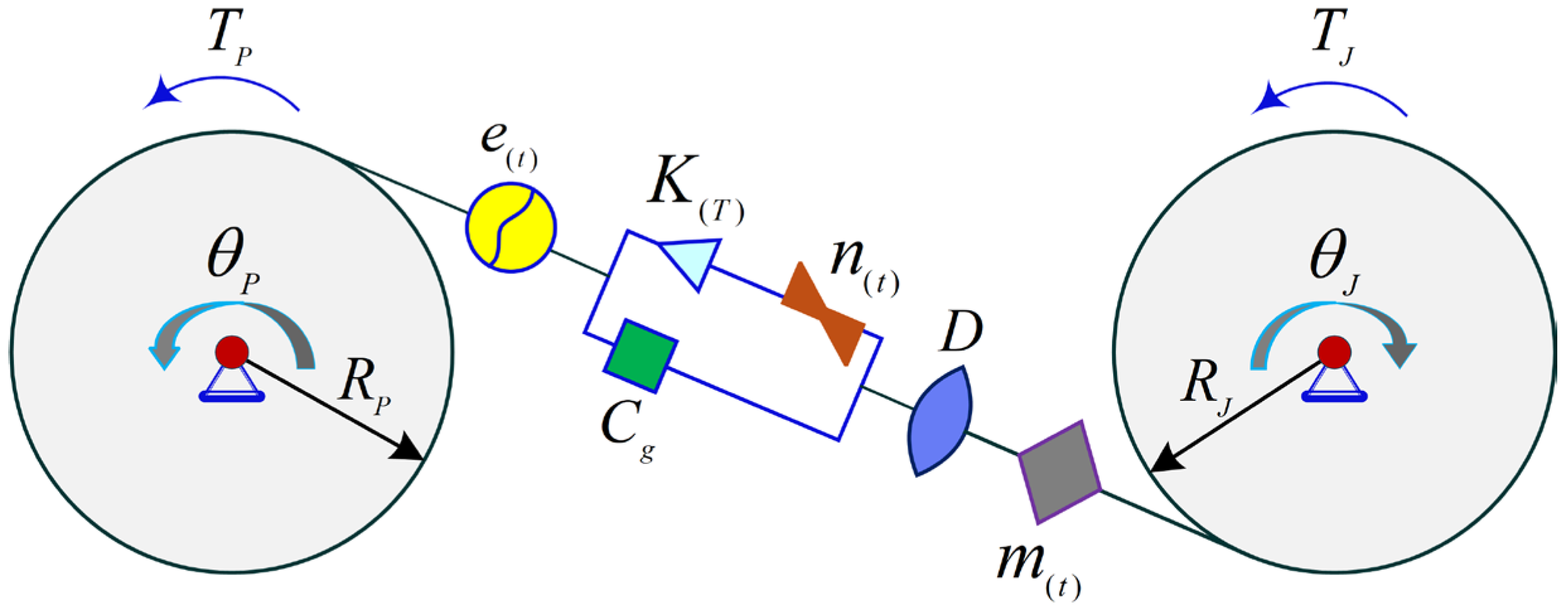
Based on the meshing state of the deep-sea space line contact interface [
41], the normal contact pressure at the lateral meshing interface of the driven gear remains positive, and the relative displacement along the meshing line exceeds the tooth flank clearance. The meshing interface contact pair is simplified as a rigid support state, a physical model of the meshing interface torsional vibration system is established, which considers key parameters such as the interface contact friction coefficient and linear meshing damping. However, the existing physical model does not yet involve the influence of multiscale micro-texture characterization on meshing characteristics. To address this, the current study focuses on the influence of the mechanism of the micro-textured meshing interface characteristics and proposes a novel physical model that can reflect the meshing response of the micro-textured interface, as shown in
Figure 1, to explore the correlation mechanism between the micro-textured interface characteristics and the gear meshing behavior.
In a gear transmission system (see
Figure 2),
and
denote the torques of the driving gear and the driven gear, respectively.
and
represent the rotation angles of the pinion gear and the large gear, respectively.
and
correspond to the base circle radii of the pinion gear and large gear, respectively.
represents the backlash between the gear pair, and
is the linear meshing damping of the gear pair.
denotes the time-varying friction coefficient of the gear, and
is the Time-Varying Meshing Stiffness (TVMS) of the gear pair.
represents the dynamic transmission error of the gear pair. Assume that the gear pair is in perfect meshing, i.e., it is presumed that no gear meshing error exists. The dynamic transmission error
satisfies the following relationship:
, where
is the error fluctuation coefficient and
is the meshing frequency. Here,
represents the linear influence factor of the textured meshing interface on the TVMS (
). According to D’Alembert’s Principle, the dynamic equation of the gear pair can be expressed as
The equation system considers nonlinear factors such as time-varying meshing stiffness , dynamic friction coefficient , backlash , and dynamic transmission error , providing a complete description of the dynamic behavior of the gear pair under ideal meshing conditions. When the pinion and gear rotate at low speeds, the derivative terms can be neglected.
2.2. Meshing Pairs Contact Deformation Mechanism and Modeling Analysis
In traditional Hertzian contact analysis, the bending deformation of gear teeth is usually disregarded. However, this simplification can introduce computational errors associated with the method into the simulation and analysis processes, which may in turn compromise the accuracy and reliability of the results [
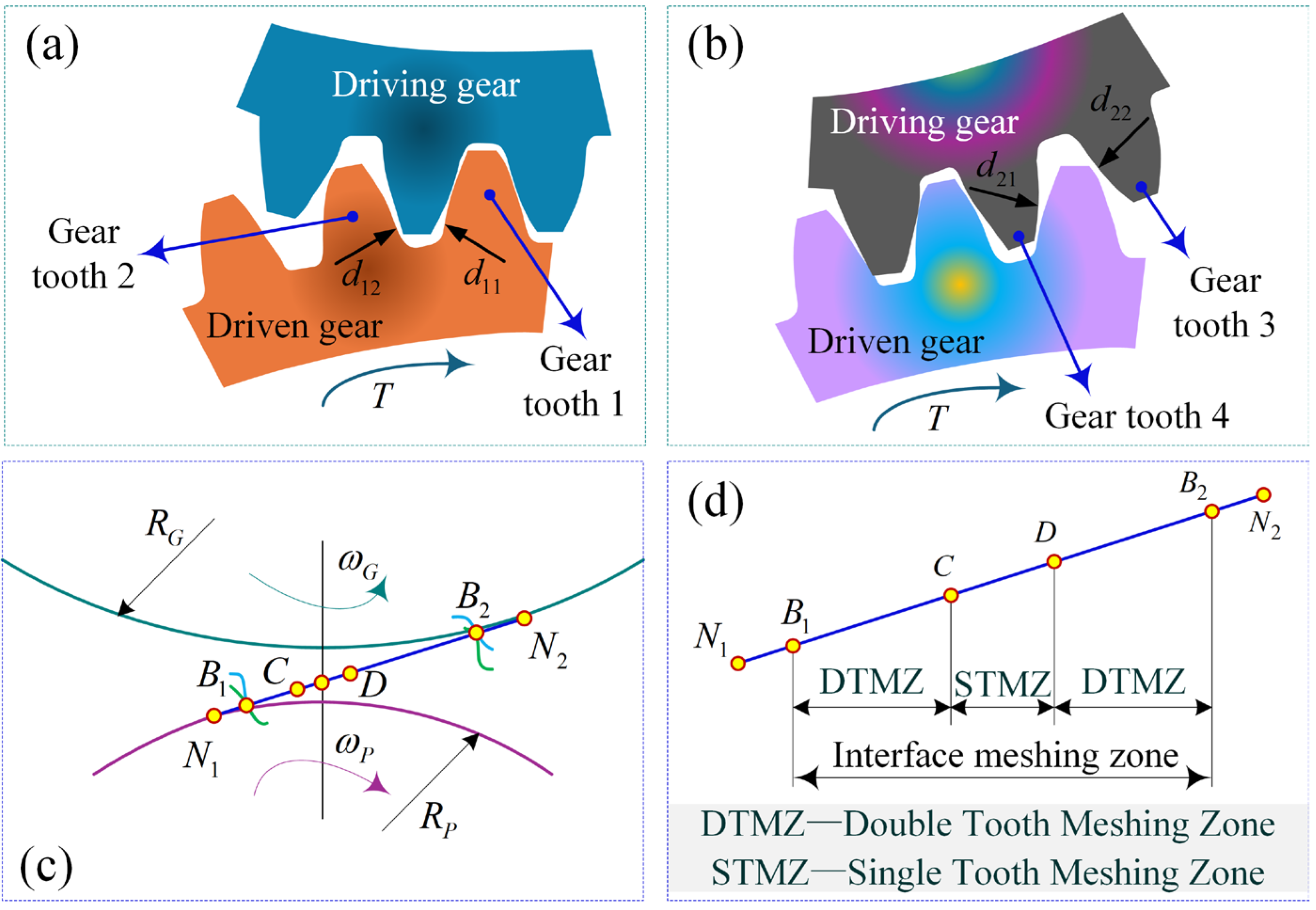
42]. During the transition phase of gear meshing contact, the dynamic characteristics of the meshing position exhibit pronounced nonlinear behavior. When shifting from Double Tooth Meshing Zone (DTMZ) to single Tooth Meshing Zone (STMZ), the contact points primarily concentrate near the tooth tip region of the pinion, as illustrated in
Figure 2a. In this scenario, gear tooth 1 demonstrates substantial contact deformation along the
direction, while gear tooth 2 maintains minimal deformation with higher stiffness characteristics along the
direction. This stiffness disparity results in a hysteresis effect of the actual double-to-single tooth transition position compared to theoretical analytical predictions.
Conversely, during the transition from STMZ to DTMZ, the meshing contact mainly occurs in the end region of the larger gear. Gear tooth 4 undergoes significant contact deformation along the
direction, whereas gear tooth 3 exhibits minimal deformation and higher stiffness along the
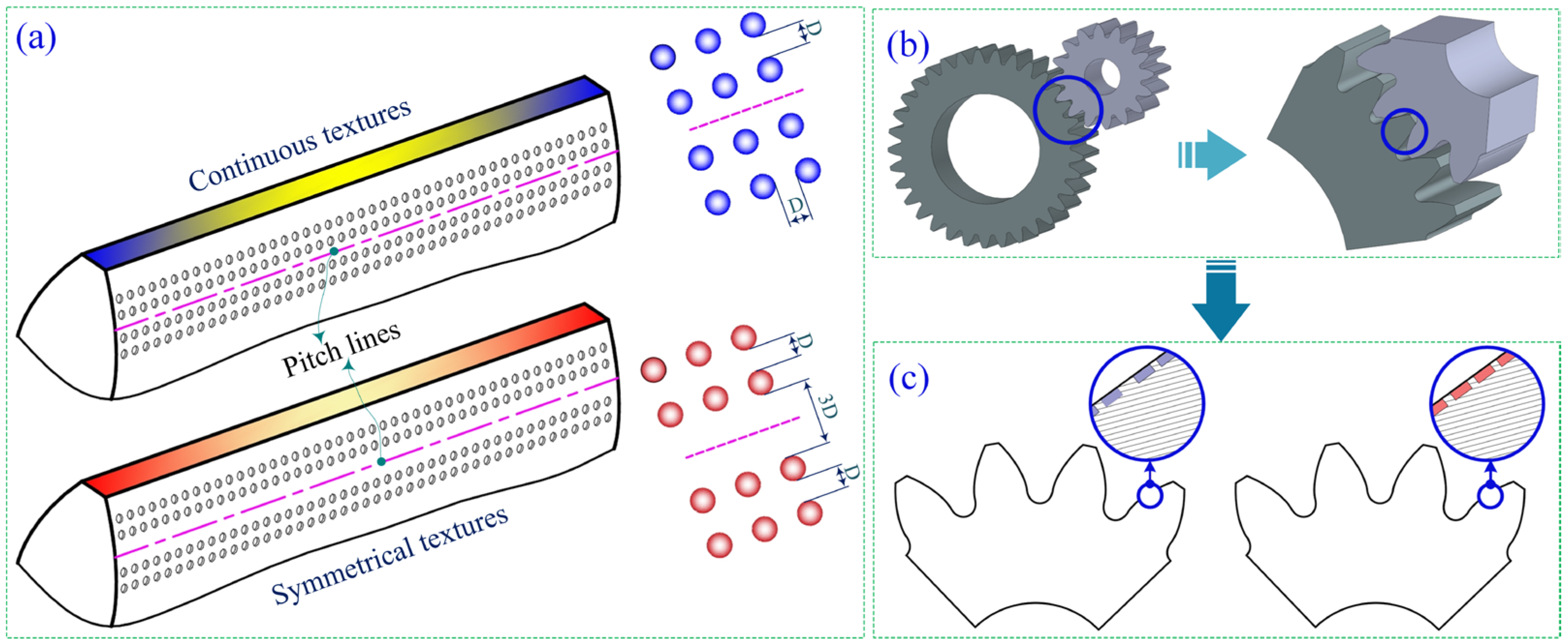
direction. This asymmetric stiffness distribution causes the actual single-to-double tooth transition position to advance ahead of the theoretical position. These observed positional deviations in meshing transitions reveal the critical influence of non-uniform stiffness distribution on the dynamic characteristics of gear meshing. The findings provide essential theoretical insights for optimizing the dynamic performance of gear transmission systems. In the transmission process, the non-uniform contact deformation during the transition between the STMZ and the DTMZ can lead to a significant polygonal effect under instantaneous meshing-in/meshing-out conditions. This effect not only exacerbates gear pair vibrations but may also cause adhesive failure due to inadequate lubrication and disengagement of the meshing interface in the driven gear (large gear) resulting from elastoplastic deformation. The present study proposes the preset of dimple-shaped micro-element texture configuration on the meshing interface near the pitch line of the driving gear (pinion), as illustrated in
Figure 2c,d. By establishing the equilibrium differential equations of elastic mechanics and incorporating identical force analysis, the results demonstrate that the preset textured micro-units can effectively enhance local contact stress of the meshing interface while maintaining constant total meshing stress. This micro-texture configuration not only improves stress distribution characteristics and enhances the gear pair lubrication performance of the dynamic contact interface, but also effectively increases the meshing anti-scuffing load-bearing capacity, providing a novel technical approach to addressing key failure issues in gear transmission systems.
The driving gear (pinion) is preset with dimple-shaped micro-element texture configuration on the meshing interface to investigate the evolution characteristics of interfacial contact properties during dynamic meshing. The meshing zone transitions from the DTMZ to the STMZ, gear tooth 2 exhibits increasing contact stress and deformation along the direction at the meshing interface, while gear tooth 1 demonstrates reduced contact stress and deformation along the direction, despite positional changes, the contact stiffness in this zone significantly increases. During the transient deformation process of gear pairs, the meshing interface evolves from line contact to surface contact. This transformation in contact form can lead to a more complex distribution of contact stress, thereby increasing the risk of meshing failure. The introduction of micro-element texture features effectively improves contact deformation behavior at the meshing interface. When switching from DTMZ to STMZ, textured gears demonstrate enhanced contact stiffness and reduced polygon effects, thereby significantly improving the transmission service life. Similarly, when transitioning from STMZ to DTMZ, the contact stiffness of textured gear pairs also increases. This finding holds substantial theoretical significance and engineering value for mitigating the adverse effects of line/surface contact during meshing processes, ultimately providing innovative technical insights for the design and manufacturing of high-performance gears.
2.3. Contact Characteristics Analysis of Micro-Textured Meshing Interfaces
According to classical contact mechanics theory, the contact characteristics analysis of at meshing interfaces can be simplified as an opposing contact problem between a pair of parallel cylindrical axes, as illustrated in
Figure 3a. The modeling process incorporates the following assumptions: The contact surfaces are smooth and continuous without macroscopic defects; the contact deformation is much smaller than the contact zone dimensions, satisfying the small deformation condition; the stress and deformation fields under normal and tangential loads are mutually independent, conforming to the principle of linear superposition; and the cylindrical materials are isotropic linear elastic bodies that can be equivalently modeled as an elastic half-space.
Figure 3b presents an enlarged view of the contact zone within the meshing region, demonstrating the geometric morphology and stress distribution characteristics of the contact zone. The location of point
on the meshing surface, which is at a certain distance from point
, can be simplified as a concentrated load perpendicular to the gear profile surface acting on the unit width d along the tooth width direction. Based on the assumptions of the traditional gear contact model, which assumes consistent geometric features along the tooth width direction, the distribution pattern of the meshing pair end face stress is analyzed to reveal the mechanical behavior characteristics of the gear contact interface. This study focuses on the contact characteristics of micro-textured interfaces. When the micro-textured interface engages with dimple-shaped micro-element textures, the contact line morphology undergoes significant dynamic evolution, as illustrated in
Figure 3. When the preset of a dimple-shaped micro-element texture configuration exists on the meshing interface, these textured micro-elements features can cause localized separation in the flank regions that should otherwise maintain contact. Traditional contact stress analytical methods typically neglect variations in the contact line length along the tooth width direction. However, research [
43] has shown that the contact line length on the flanks of micro-textured meshing interfaces is significantly shorter compared to non-textured gears. Therefore, this paper considers the influence of micro-texture arrangement patterns on the contact line within the meshing zone and establishes an analytical model for contact stress on micro-textured meshing interfaces. Under the combined action of normal and tangential loads, the contact stress components in this model can be formulated. The textured interface normal contact stress within the meshing zone is expressed as
where,
denotes the normal contact stress of the meshing interface,
is the total number of dimple-shaped micro-element textures distributed along the tooth width direction,
is the width of the contact line,
represents the length of the contact line on the interface during the transient meshing process (the contact width of the meshing zone), and
signifies the chord length dimension of the dimple-shaped micro-element textures.
When
, the maximum normal contact force of the interface within the meshing domain is determined
During the interface meshing transient process,
represents the time-varying equivalent contact radius (dynamically changing),
denotes the equivalent elastic modulus of the material. The interfacial tangential contact force in the meshing zone is formulated as
where
.
When
, the maximum normal contact force of the interface within the meshing domain is expressed
Integrating the loaded zone, and stress components under the action of the normal force (
) is derived
By integrating the loaded zone, the stress components under the action of the tangential force (
) are obtained
The parameters
and
in the above equation are calculated through the following expressions:
Substituting the above equation allows for the determination of the stress components at point A on the meshing interface under the coupled action of normal and tangential contact forces:
Considering the deformed meshing interface, the principal shear stress
is expressed as
The contact zone width, normal contact stress, and tangential contact stress exhibit a negative linear correlation with the square root of the actual contact line length, while the tangential and normal components of contact stress are negatively linearly related to the actual contact line length itself. This correlation leads to a significant increase in shear stress at the deformation meshing interface when the actual contact line length decreases. As gear pair meshing motion enters the textured interface micro-element zone, the contact geometric conditions of the meshing interface change, and the stress at the textured meshing interface will rise sharply. This phenomenon demonstrates that micro-texturing meshing interface has a significant impact on the contact stress of gear pairs, especially when contact line length variations occur, resulting in more pronounced stress fluctuations. These findings provide crucial theoretical insights for understanding the effects of textured interfaces on the contact mechanical behavior of gear pairs.
4. Analysis of Simulation Results
4.1. Hypothesis of Dynamic Alternating Distribution of Contact Lines on Micro-Textured Gear Meshing Interfaces
The lubrication and load-bearing of heavy-duty gears has long been a prominent frontier research topic in mechanical engineering. The interface contact line of involute gear pair is the cornerstone of meshing dynamics. The maintenance of constant transmission characteristics along the meshing direction is the theoretical basis for stable load-bearing, a principle that has gained widespread recognition within the industry (Derived from: ISO 6336-1:2019, Calculation of load capacity of spur and helical gears—Part 1: Basic principles, introduction and general influence factors. Dudley, D.W. (1994), Handbook of Practical Gear Design, CRC Press). Based on the analysis of the interface contact line within the meshing domain, this study boldly proposes an innovative hypothesis that the meshing contact line is not fixed but has a time-varying characteristic of dynamic alternating distribution.
This study boldly proposes an innovative hypothesis through meticulous analysis of interfacial contact lines within the meshing domain: the meshing contact line demonstrates dynamic alternating distribution characteristics rather than remaining static. A uniformly arranged system of textured meshing interface micro-elements is constructed to achieve continuous symmetrical expansion of the meshing line towards both sides of the interface, as shown in
Figure 7a. The geometric shape of the expansion deformation line follows the mathematical definition of the textured gear involute meshing contour, and the diameter of the dimple-shaped micro-texture corresponds to the total expansion deformation length.
To construct a uniform arrangement regularized system of textured meshing interface microelements, continuous symmetrical expansion of the meshing line towards both sides of the interface is realized. The initial geometric configuration of the involute at the textured interface microelement directly determines the distribution form of the meshing contact line. Traditional non-textured meshing interfaces are characterized by single-line contact, as shown in
Figure 7b, whereas textured meshing interfaces display dual-line contact characteristics, as illustrated in
Figure 7c. This characteristic originates from the synergistic control mechanism between the interface microelement texture and the meshing position. During the contact process of the gear pair, neither the meshing stress distribution of the textured interface nor the contact state of the microelement scale configuration shows any abrupt change. The TVMS of micro-textured gear pairs is significantly enhanced compared to traditional non-textured gear pairs and demonstrates greater stability. This study proposes a novel concept of symmetrically extended contact lines, where the meshing interface maintains a constant state along the tooth width direction, with the contact lines being two-dimensional straight lines. Compared with the initial meshing line, this meshing line has symmetrical extended directions that offset each other, which greatly increases the total length of the meshing line while keeping the total contact load unchanged. The purpose is to ensure the stability of meshing load-bearing when the dynamic contact of the microtextured interface is homogeneously distributed. The microtextured meshing interface is applied, this approach remarkably mitigates interfacial contact stress concentration and substantially increases the proportion of functional micro-textured zones. As a result, it achieves synergistic optimization and improvement in both interface enriched lubrication and meshing load-bearing performance.
4.2. Transient Contact Stress/Strain Analysis of Interface Meshing Zones
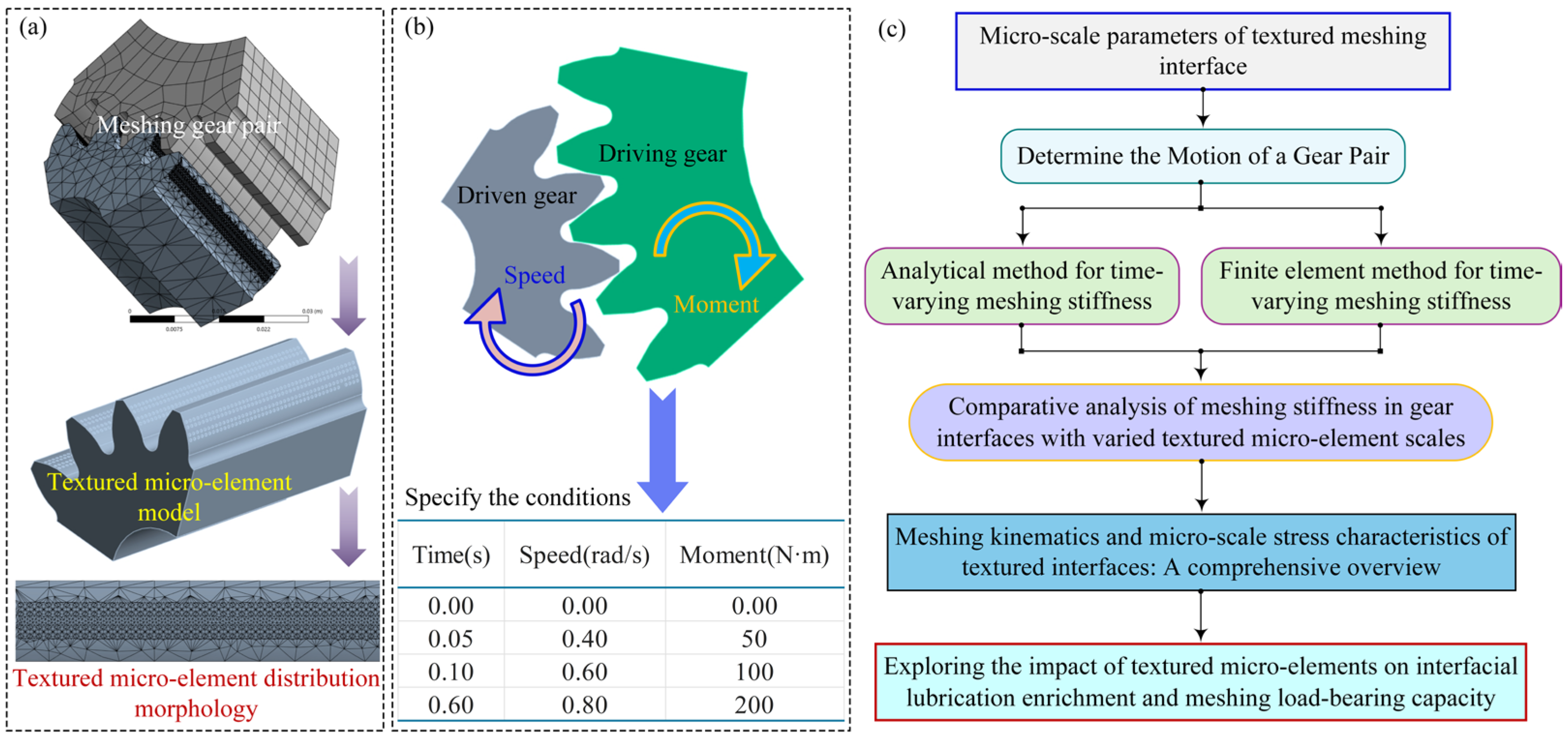
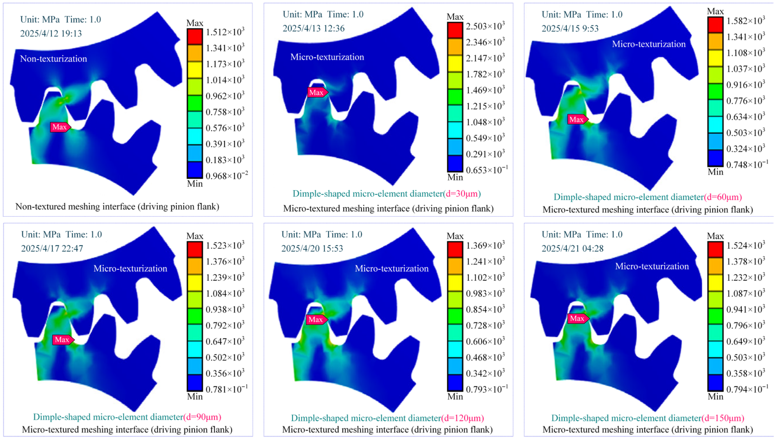
This chapter focuses on the contact stress and strain characteristics of micro-textured interfaces during meshing transient processes, as illustrated in
Figure 8. A comprehensive study is proposed to explore three fundamental micro-texturing topologies: a non-textured control interface, unidirectionally continuous micro-element distributions, and bilaterally symmetrical micro-textured architectures.
The findings demonstrate that the contact stress and strain characteristics vary significantly among the three types of interfaces. Notably, the micro-textured interfaces display a more uniform stress distribution and a lower strain amplitude. The numerical simulations indicate that the maximum stress peak in the textured meshing interface appears in the bottom zone of preset microelements, where it is characterized by a locally minimal contact zone and a tendency for stress extremum diffusion. The mechanism behind this phenomenon can be attributed to the local stress peak concentration caused by the right-angle configuration microelement effect formed between the cylindrical wall of circular dimple-shaped textures and its bottom planes. However, it is important to note that, from the perspective of the meshing transient process, the influence of such localized stress concentration is extremely limited and is considered negligible.
The numerical simulation results reveal a critical phenomenon: micro-textured interface elements play a pivotal role in stress transmission within meshing pairs. Contrary to conventional understanding that stress peaks predominantly occur near the meshing interface, the findings demonstrate that maximum stress concentrations are localized at the base of individual micro-textured elements. Through precise pre-design of micro-texture geometry and dimensional parameters, this stress concentration phenomenon can be effectively mitigated. Such optimization not only prevents lubrication failure at the interface but also significantly reduces dynamic stresses during meshing operations. Consequently, both the load-bearing reliability and service life of meshing pairs are substantially enhanced. This optimized stress and strain behavior enhances the stability of interface lubrication, which in turn ensures the long-term durability and load-bearing capacity of the meshing mechanism during extended operation.
The stress distribution patterns of non-textured and micro-textured meshing interfaces are illustrated in
Figure 9. The non-textured interface demonstrates relatively stable strain and stress variations with minimal fluctuations. However, notable stress concentration and increased strain amplitude are observed in the gear tooth root zone and its adjacent areas. The introduction of micro-textured elements effectively mitigates stress concentration issues in these critical zones during gear meshing. During the transient meshing process of the gear pair, the distribution of contact stress is of crucial importance. The continuous micro-textured meshing interface exhibits a greater stress increment compared to the symmetrical micro-textured interface, with stress peak concentration areas displaying a typical band-like elliptical distribution pattern. This discrepancy stems from the fundamental difference in dynamic stress dissipation mechanisms between the two types of micro-textured interfaces. The continuous micro-textured interface fails to achieve effective dynamic stress dissipation during meshing process, whereas the symmetrical micro-textured interface, through a unique element configuration design, can effectively release the high-amplitude dynamic stresses generated by slip motion discontinuity near the pitch line contact area, thereby preventing excessive stress concentration.
Analysis reveals that the stress variation amplitude on micro-textured meshing interfaces is significantly higher than that on non-textured ones. This is primarily due to the contact stress transfer mechanism resulting from the gears pairs meshing characteristics. The scale and configuration of the micro-texturing elements create localized stress extremum points, which complicate the stress distribution patterns, while simultaneously presenting novel opportunities for stress distribution optimization. By reasonably designing the scale and configuration of the micro-texturing elements, the stress distribution can be adjusted to actively modulate stress distribution characteristics. This optimization approach offers a promising pathway to enhance the load-bearing capacity of gear pair meshing interfaces.
During the transient process of increased contact stress in a gear pair, the initial meshing stress of the micro-textured interface is similar to that of the non-textured interface.
Figure 10 illustrates the temporal evolution of dimensionless contact stress during the meshing process of textured interfaces under low-speed (0.8 rad/s) and heavy-load (0.2 kN·m) conditions. When the meshing gear teeth rotate to a position of 6°, the contact stress of the micro-textured meshing interface demonstrates a sharp upward trend. This phenomenon can be attributed to the significant local stress concentration effect induced by the micro-textures on the interface. The micro-textured interface is capable of effectively transferring and redistributing to the contact stress, thereby markedly enhancing the stress concentration level in the rolling-sliding line contact pair. As an efficient technical approach, interface micro-texturing can regulate contact stress distribution to elevate the stress concentration degree of meshing pairs, consequently suppressing both the initiation and propagation of interface failure.
The meshing interface with micro-textured patterns can generate significant contact stress peaks during transient processes. The non-textured meshing interface exhibits a band-like elliptical characteristic of contact stress peaks, with a larger contact area of the meshing zone subjected to high-pressure regions, which is the primary cause of gear tooth fractures. Comparatively, the micro-textured meshing interface achieves a more homogeneous distribution of contact stress, with peak stress values that are notably lower than that of the non-textured interface.
4.3. Synergistic Regulation of Meshing Stiffness and Load-Bearing Characteristics for Transient Contact Process of Micro-Textured Interfaces
The dynamic regulation mechanism of meshing stiffness during micro-texture transient contact represents a core scientific issue affecting interface load-bearing performance. By predesigning multi-scale microelement configuration characteristics, real-time adjustment of meshing stiffness can be achieved, thereby regulating interface load-bearing capacity. This study provides crucial theoretical foundations for achieving homogenized load distribution through optimized interface microelement configuration. When the friction coefficient increases, the friction characteristics of the textured meshing interface tend to decrease. The trend of friction characteristics in micro-textured meshing interfaces is consistent with that of non-textured interfaces, indicating that the presence of micro-textured features does not alter the fundamental frictional behavior of the meshing interface. Considering the multi-scale textured micro-element configuration features of contact interface, the TVMS variation curve is shown in
Figure 11. The diameters of textured micro-elements are set to 50 μm, 100 μm, and 150 μm, respectively. As the diameter of textured micro-elements gradually increases, the TVMS variation curve demonstrates a smoother trend. When the diameter of textured micro-elements is 100 μm, the TVMS variation in contact interface is the most stable. This phenomenon indicates a remarkable enhancement in the load-bearing capacity of micro-textured interfaces, which fundamentally stems from the polygonal scale effects contributed by the micro-element configuration which enables the contact stress between the gear pairs to be more homogeneously distributed. The peak stress concentration phenomenon during single-to-double tooth transition phases is effectively mitigated, thereby suppressing potential failure risks caused by elastic deformation at the meshing interface.
After micro-texturing modification, the TVMS of the gear pair interface exhibits significant evolution: compared with an untreated tooth surface, its stiffness amplitude decreases by 5.32% (see
Table 3), and the fluctuation amplitude during the meshing cycle is effectively suppressed. Meanwhile, the abrupt changes in stiffness at the instants of mesh engagement and disengagement are noticeably mitigated. These observations indicate that micro-texturing reshapes the dynamic stiffness characteristics of the interface by introducing controlled elastic deformation and coupling it with local oil film stiffness.
Considering the transition process from double-tooth to single-tooth meshing and the influence of the contact pairs friction coefficient, the TVMS tends to increase with the rotation angle of the driving pinion. However, during the transition from single-tooth to double-tooth meshing, the TVMS exhibits a downward trend. Such time-varying c behavior is absent in non-textured meshing interfaces. This phenomenon can be attributed to the combined effect of a high friction coefficient and the meshing-out conditions. The introduction of micro-textures significantly enhances the friction effect between the contact pairs, thereby improving the meshing load-bearing capacity and effectively suppressing the wear behavior. Furthermore, in both single and double tooth meshing regions, the enhancement effect of textured meshing interfaces on TVMS demonstrates distinct regularity, providing a theoretical foundation for optimizing gear transmission performance through interface texturing design.
5. Discussion
The lubrication performance between meshing pairs in confined deep-sea gear environments is often unsatisfactory, leading to stress concentration peaks and subsequent issues such as scratches, adhesion, and adhesive failure during alternating contact processes. Priority should be given to texturing the meshing interface and presetting the micro-scale configuration, as shown in
Figure 12a. The nominal friction coefficient of the textured interface contact is higher than that of the untextured one, and it increases gradually with the continuous increase in the texture micro-element diameter. This phenomenon is mainly due to the fact that the texture micro-element scale characteristics lead to an increase in the shear stress of meshing interface. The critical role of texture micro-elements in achieving homogeneous stress distribution and stable load-bearing capacity across the meshing interface has been well established. This has been discussed in previous studies [
44,
45,
46] on the influence of texture micro-element scale morphology on friction coefficient.
The micro-textures parameters have a significant impact on the friction characteristics of meshing interface. When the diameter of micro-texture element is
d = 30 μm, the nominal friction coefficient of meshing interface reaches the minimum increase. Analysis of the variation in friction coefficient for micro-textured meshing interfaces as shown in
Figure 12b. When the friction coefficient is set within the 0.20–0.30 range and the diameter of micro-texture element is
d = 120 μm, the amplitude of the time-varying contact friction coefficient exceeds that of non-textured interface. However, under other parameter combinations, microtexturing can effectively reduce the fluctuation amplitude of friction coefficient. When the friction coefficient is set at 0.10 and the diameter of micro-texture element is
d = 30 μm, the meshing contact stability demonstrates a remarkable 53% improvement compared to the non-textured interface. This crucial finding strongly indicates that the coordination capability of micro-textured friction contact interfaces can be effectively applied to gear pair meshing interfaces. Numerical simulation results further indicate that the improvement effect of micro-textures becomes more pronounced under low friction coefficient conditions. The underlying mechanism lies in the fact that under low friction coefficients, wear-induced deformation failure caused by relative sliding at the meshing interface leads to reduced contact stress. In this scenario, the texture elements effectively enhance the contact stress of the meshing interface while regulating transient deformation during the meshing process. This dual effect mitigates interface deformation to some extent, thereby improving both interface contact stability and meshing load-bearing performance.
6. Conclusions
The demand for high reliability, long-term stability, high power density, and stress peak capacity in deep-sea spatial equipment is increasingly critical. The issues of lubrication failure and meshing load-bearing failure of gear pair interfaces have become key bottlenecks restricting the performance enhancement of rear transmission systems. As is well recognized, micro-textured interface fabricated through micro-machining technology can effectively regulate the meshing conditions of gear pair contact friction system. This study introduces micro-texturing into heavy-duty gear pairs and finds that the multi-scale configuration of textured micro-elements has an independent effect on the lubrication characteristics and load-bearing performance of meshing interfaces. This influence mechanism does not rely on gear surface strengthening measures but rather achieves precise regulation of interfacial lubrication properties and meshing load-bearing capacity through its unique pre-designed structural characteristics, thereby opening new avenues for addressing the anti-scuffing load-bearing challenges of heavy-duty gears in advanced deep-sea equipment. The following conclusions are drawn:
- (1)
Under heavy loads (high-stress) and low-speed conditions, the time-varying meshing stiffness of gear pair treated with microtexturing is significantly enhanced by 5.32%, and the fluctuation amplitude is also greatly reduced (compared with the ungeared gear pair, the minimum difference reaches 5.2%). This optimization significantly improves the meshing load-bearing stability of gear pair, thus providing robust reliability assurance for gear transmission system.
- (2)
The introduction of micro-textures on the meshing interface of the driving pinion effectively optimizes stress distribution characteristics between contact pairs (by redistributing peak stresses within the yield strength limit). The extreme value of the meshing stress of the textured micro-element interface is significantly reduced by 21%. Although localized stress concentration persists at the base of individual textured micro-element, these high-stress areas have the following characteristics: (1) extremely limited spatial scale, (2) isolation from primary meshing contact areas, and (3) negligible impact on overall stress distribution optimization. The micro-texturing technology application not only significantly improves interfacial stress field distribution, but more importantly, effectively mitigates lubrication failure risks, thereby substantially extending the service life of gear pairs under heavy-load conditions.
- (3)
The regulatory effect of micro-texture elements on the meshing characteristics of gear pairs is undeniably significant. A clear negative correlation exists between the contact friction coefficient and the Time-Varying Meshing Stiffness (TVMS) of gears. By modulating the friction coefficient at the contact interface, the meshing stability can be notably enhanced, with the potential for an increase of up to 51.8%. This adjustment also effectively diminishes the relative sliding contact friction during the transient meshing process, particularly at the critical initial stage of meshing-in. Experimental results corroborate these findings, showing that implementing micro-textured interface elements at the meshing-in initial stage can reduce maximum friction torque by 27.3%. These comprehensive findings substantiate that micro-texture elements serve as an effective technical solution for optimizing gear transmission performance by precisely regulating gear pair meshing characteristics.
The introduction of micro-textures can significantly enhance the gears meshing Anti-Scuffing Load-Bearing Capacity (ASLBC) under the condition of Interface Enriched Lubrication (IEL). This finding provides an important theoretical basis for the optimal design of textured micro-element configurations and the improvement of meshing dynamic performance. However, current research on the influence of micro-textures on gears meshing ASLBC under IEL conditions still exhibits notable deficiencies. The application reliability under extreme working conditions has not yet been fully verified, which means that the promotion and application of this technology in the heavy industry field still face many technical problems that need to be solved urgently. It should be noted that the preset micro-textured element configuration scheme adopted in this study still has limitations in specialized applications such as deep-sea gear transmissions. Compared with the in-depth discussion of the thermal elastic effect and the thermo-mechanical coupling effect in previous studies, the consideration of these critical influencing factors in this work still needs to be further improved.
