Abstract
Permanent magnet vernier motors (PMVMs) have significant advantages in low-speed direct-drive fields on account of their high torque density, and their performance improvement is still a research hotspot. To enhance the overall electromagnetic performance and provide an alternative solution for low-speed direct-drive applications, this paper proposes a permanent magnet vernier motor with rotor auxiliary teeth (denoted as “RAT-PMVM”). Firstly, the structure and working principle of RAT-PMVM are introduced. Then, the two-dimensional (2D) finite element method (FEM) is used to comparatively study the influence of the number, position, and tooth profile of the rotor auxiliary teeth on the electromagnetic performance of the proposed motor. The results show that the RAT-PMVM with trapezoidal teeth (denoted as “TT-PMVM”) achieved improvement in output torque, efficiency, and power factor: the output torque increased from 11.32 Nm to 14.19 Nm, the efficiency increased from 88.5% to 92.2%, and the power factor increased from 0.60 to 0.71. Finally, in order to further reduce the torque ripple and improve the torque, power factor, and efficiency, multi-objective optimization of the TT-PMVM is carried out. The optimization yields a 27.3% increase in torque, a 31.8% reduction in torque ripple ratio, an efficiency improvement from 92.2% to 93%, and a power factor enhancement from 0.73 to 0.81, demonstrating significant potential for low-speed direct-drive applications like industrial robots and wind power generation.
1. Introduction
Permanent magnet (PM) motors are extensively used as electromagnetic energy conversion devices in industrial applications and domestic appliances, such as industrial robots, wind power generation, electric vehicles, air conditioning systems, washing machines, and hair dryers. For low-speed high-torque direct-drive applications, PM motors are particularly favored for their high torque density and efficiency, which often eliminate the need for mechanical gearboxes [1]. Among PM motor topologies, the permanent magnet vernier motor (PMVM) stands out for its exceptional torque density, operational reliability, and efficiency, making it suitable for low-speed direct-drive scenarios [2]. However, despite these advantages, PMVMs also have some shortcomings, such as high iron losses due to rich harmonic fields [3], significant cogging torque [4], potential risks of PM demagnetization under severe operating conditions [5], and relatively low power factor [6], which necessitates careful design and optimization [7].
The working principle of the PMVM is based on the field modulation effect (FME) [8], which allows the design of the pole-pair number (PPN) of the armature windings to differ from the PPN of the rotor magnets, while also enabling torque generation by harnessing rich magnetic field harmonics. Recent research efforts have focused on improving the electromagnetic performance of PMVMs through developing novel topologies or optimizing existing ones. For example, Ref. [9] designed a surface-mounted PMVM to make a good compromise between torque density and power factor through constructing closed-form per-unit equations. Ref. [10] proposed a five-phase fault-tolerant interior PMVM for high reliability and high torque density at low speed. Ref. [11] designed and analyzed a consequent-pole PMVM to reduce PM material cost, cancel even-order harmonics, and achieve high torque density. Ref. [12] proposed a new PMVM with both yoke PMs and slot PMs on stator for torque enhancement. Ref. [13] developed and analyzed a V-shaped PMVM with dummy slots in the rotor for reducing flux leakage, enhancing the output torque, and suppressing the torque ripple. Ref. [14] presented a novel fractional-slot H-shaped PMVM to enhance torque density and decrease cogging torque. Ref. [15] designed a special L-shaped PMVM to reduce the leakage flux lines in the end portion of the PMs, which enhanced flux linkage and power factor. Ref. [16] proposed a novel design of PMVM with a T-shaped consequent pole rotor, which can increase fundamental airgap flux density, PM utilization ratio, and output torque. Ref. [17] presented a PMVM with saddle-shaped PMs to improve torque and reduce torque ripple. Ref. [18] designed and analyzed two five-segment Halbach-array PMVMs with two different slot/pole combinations to achieve a high torque density with an acceptable power factor, while maintaining a low torque ripple. Ref. [19] developed a spoke-array PMVM with magnets bridge, which can effectively restrict the flux barrier effect and improve electromagnetic performance. Ref. [20] proposed a spoke-type PMVM with an unaligned stator auxiliary teeth arrangement to significantly enhance the field modulation effect, back-electromotive force (Back-EMF), and electromagnetic torque. Ref. [21] explored a consequent-pole K-shaped PMVM, which has the advantages of spoke- and V-shaped magnetic arrangements. Ref. [22] proposed a PMVM with coding-shaped teeth, which can introduce permeance harmonics with a specific phase and amplitude to ensure that modulating flux fields contribute to the torque output. Ref. [23] developed a PMVM with an unequal stator modulated teeth structure to reduce electromagnetic vibration. Ref. [24] proposed a straight-tooth PMVM with Halbach-array magnets in a stator slot opening to improve Back-EMF and power factor. Ref. [25] comparatively analyzed two split-tooth PMVMs with evenly and unevenly distributed modulation teeth, and the results verify that the PMVM with unevenly distributed modulation teeth outperforms the one with evenly distributed modulation teeth. Ref. [26] developed a consequent-pole PMVM with an uneven distribution of armature teeth and fault tolerant teeth to generate asymmetric airgap field distribution, improve its working harmonics, and reduce PM consumption. Ref. [27] explored a PMVM with specially designed stator auxiliary teeth, which can achieve higher torque density than that of a regular nonoverlapping winding PMVM with the same magnet usage. Ref. [28] proposed a V-shaped PMVM with unequal-width stator slots for cogging torque and torque ripple suppression, while the desired torque output capability is maintained. Ref. [29] designed and analyzed a PMVM with an asymmetric-stator-pole configuration, which introduces the consequent-pole structure, auxiliary slots, Halbach array, and overhang structure to improve the PM utilization and torque density. In terms of optimization, Ref. [30] employed a multi-objective genetic algorithm to optimize the V-shaped PMVM, enhancing torque density and reducing torque ripple. Ref. [31] was devoted to identifying the optimal pole ratio of a spoke-type PMVM by equivalent magnetic circuit model. Ref. [32] efficiently and accurately optimized a spoke-type PMVM by leveraging multi-level sensitivity analysis, approximate model, and multi-objective genetic algorithm to enhance torque density and power factor. Ref. [33] optimized a spoke-type PMVM accounting for eccentric pole-arc shape by an analytical method. Ref. [34] used a novel numerical model to optimize the output torque, torque ripple, efficiency, and power factor of a PMVM.
Cogging torque remains a critical electromagnetic performance in PM machines, including PMVMs. Several techniques have been developed to mitigate cogging torque. For instance, Ref. [35] comprehensively reviewed skewing techniques for cogging torque suppression in permanent magnet synchronous motors (PMSMs), including continuous skew, step skew, and notch skew. Ref. [36] comprehensively investigated and evaluated the cogging torque suppression techniques of flux-switching permanent magnet machines, such as skewing stator, skewing rotor, step-skewing rotor, asymmetric stator and rotor structures, the successively shifting and alternately shifting rotor teeth techniques, pairing rotor, chamfering, and tooth notching. Ref. [37] adopted auxiliary slots on the rotor to minimize the cogging torque of V-type interior PMSMs. Ref. [38] proposed a method to reduce cogging torque in PM machines by shifting the elementary-cogging unit. Ref. [39] designed, analyzed, and fabricated a fully coreless axial-flux PM generator for eliminating cogging torque and eddy current losses, enhancing efficiency. Ref. [40] pointed out that cogging torque can be mitigated by increasing the least common multiple of the slot–pole combinations. Refs. [41,42] presented tooth-shaping methods to reduce the cogging torque of axial-flux PM machines. Refs. [43,44] minimized cogging torque by designing proper magnet shapes. Ref. [45] applied a magnet-shifting design for a PMVM to reduce cogging torque as well as torque ripples. Ref. [46] employed the design of non-uniform tooth distribution in PMVM to reduce cogging torque and enhance output torque.
Another notable issue in PMVMs is iron loss, which tends to be higher due to the rich harmonic content resulting from the field modulation effect. Several methods have been proposed to reduce iron loss, including material selection, lamination design, structural design or optimization, and control strategies. For example, Ref. [47] selected amorphous magnetic material effectively as a stator core material and adopted the lamination design. Ref. [48] pointed out that D-axis flux barrier design can effectively alleviate the PM loss and core loss in fractional-slot PMVMs. Ref. [49] stated that adjusting the slot shape or introducing a flux barrier can suppress stator core loss. Ref. [50] proposed various stator modular design schemes with different slot–pole combinations to mitigate the losses in fractional-slot PMVMs. Ref. [51] presented the segmented stator design for the PMVM to achieve low loss. Ref. [52] employed the hybrid stator design for a fault-tolerant PMVM to improve its performance, including low core losses. Ref. [53] designed a new rotor structure based on the rotor losses production principle to suppress rotor losses. Ref. [54] developed a harmonic-analysis-based loss minimization method incorporated into model predictive torque control for efficiency improvement.
It can be inferred from the existing research above that developing new topologies to improve the electromagnetic performance of PMVMs remains a key focus. Inspired by the V-shaped PMVM and auxiliary tooth technology, a permanent magnet vernier motor with rotor auxiliary teeth (denoted as “RAT-PMVM”) is proposed by introducing rotor auxiliary teeth (RAT) into a V-shaped PMVM, with the purpose of enhancing overall performance. Based on the proposed RAT-PMVM, we comparatively study the influence of the number, position, and tooth profile of the RAT on the electromagnetic performance of the RAT-PMVMs, revealing superior performance in the RAT-PMVM with trapezoidal teeth (denoted as “TT-PMVM”). Finally, multi-objective optimization of the TT-PMVM is conducted to minimize torque ripple while enhancing torque, power factor, and efficiency. The innovation of this paper lies in proposing a new topology for the RAT-PMVM, which serves as a viable solution for low-speed direct-drive applications like industrial robots and wind power generation. The primary contribution of this work is that, through a comparative analysis of the impact of the number, position, and tooth profile of the RAT on the electromagnetic performance of the RAT-PMVMs, the TT-PMVM is identified as the optimal topology for its superior overall performance.
2. Motor Structure and Working Principle
2.1. Motor Structure
Figure 1 illustrates the structure of the initial permanent magnet vernier motor with rotor auxiliary teeth (denoted as “RAT-PMVM”). The proposed motor is composed of an outer stator and an inner rotor. The stator, featuring straight teeth, employs an open-slot configuration equipped with tooth tips. The three-phase armature windings with a pole-pair number (PPN) of Pw = 2 are housed in 12 stator slots; ten auxiliary teeth are incorporated into the rotor to enhance the torque performance; concurrently, ten V-shaped permanent magnets (PMs) embedded in the rotor are each aligned with an individual auxiliary tooth. The auxiliary slot is rectangular, with the rotor auxiliary tooth being an inverted trapezoid. All V-shaped PMs share identical magnetization direction, resulting in a magnetic field with a pole-pair number of Pr = 10. The specifications of the proposed RAT-PMVM are presented in Table 1. Based on the slot EMF star diagram in Figure 2a, the winding connection of the three-phase RAT-PMVM is shown in Figure 2b.
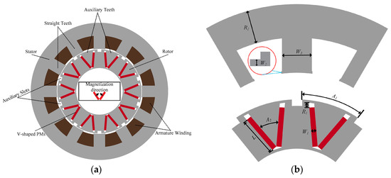
Figure 1.
Structure of the initial RAT-PMVM: (a) cross-sectional schematic; (b) geometric parameters schematic.

Table 1.
Specifications of the proposed RAT-PMVM.
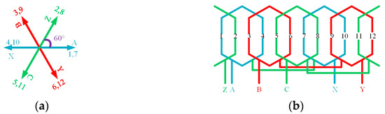
Figure 2.
Winding connection: (a) slot EMF star diagram; (b) winding layout.
2.2. Working Principle
The RAT-PMVM proposed in this paper belongs to the category of permanent magnet vernier motors (PMVMs); therefore, it operates based on the principle of field modulation effect (FME). Essentially, the FME is the so-called “magnetic gear effect”, which originates from working principle of the coaxial magnetic gear [55]. According to the “magnetic gear effect”, the fundamental magnetic field generated by the field sources (PMs and armature currents) produces numerous field harmonics traveling along the airgap under the influence of the non-uniform magnetic field paths [56]. The non-uniformity is attributed to the significant difference in magnetic permeance between the modulating teeth and their adjacent air slots. The process of harmonic generation is typically described as follows: under the FME of the modulating teeth, the magnetic field produced by the excitation source is modulated into numerous field harmonics. For example, in the case of PMs, the magnetic field excited by PMs is modulated into a multitude of field harmonics through the FME of the modulating teeth. Among these generated field harmonics, there exist effective harmonics with identical pole-pair numbers (PPNs) and rotational speeds. Through the synergistic action of these effective harmonics, either the coaxial magnetic gear or the PMVM produces a stable torque output.
For the proposed RAT-PMVM, both the three-phase armature current and the V-shaped PMs serve as field sources; likewise, both the stator teeth and the rotor auxiliary teeth (RAT) act as modulating teeth. Consequently, the armature currents and V-shaped PMs produce multiple field harmonics through their field modulation effect. Based on the “magnetic gear effect”, the harmonic pole-pair numbers (PPNs) and their corresponding rotational speeds generated by each field source will be analyzed below.
Firstly, consider the field harmonics yielded when the magnetic field excited by the V-shaped magnets undergoes the FME of the stator teeth. As shown in Figure 3, since the magnetic permeance of the stator teeth is significantly higher than that of the stator slots, the magnetic field produced by the PMs easily passes through the stator teeth but hardly penetrates the stator slots. Consequently, the waveform segments aligned with the stator teeth are preserved, while those aligned with the stator slots are attenuated. Thus, the magnetic field generated by the magnets is modulated by the stator teeth into the magnetic field indicated by the blue color. By applying Fourier series expansion to the modulated magnetic field waveform, numerous field harmonics can be observed. According to the “magnetic gear effect”, the PPN of the modulated field harmonics is given by the following equation [56,57]:
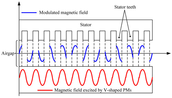
Figure 3.
Schematic diagram: PM magnetic field modulated by stator teeth.
The corresponding speed of the modulated field harmonics is governed by the following equation [56,57]:
where is the rotor speed.
Secondly, analyze the field harmonics yielded when the magnetic field excited by the V-shaped magnets undergoes the FME of the rotor auxiliary teeth (RAT). As shown in Figure 4, the waveform of the modulated magnetic field differs from that in Figure 3 due to the difference in the number of RAT compared to stator teeth. Similarly, following the magnetic gear effect, the PPN of the modulated field harmonics is given by the following equation [56,57]:
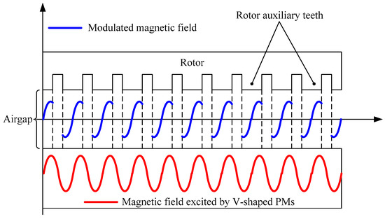
Figure 4.
Schematic diagram: PM magnetic field modulated by rotor auxiliary teeth.
The corresponding speed of the modulated field harmonics is governed by the following equation [56,57]:
Thirdly, consider the field harmonics yielded when the magnetic field excited by the three-phase armature currents undergoes the FME of the stator teeth, as shown in Figure 5. Similarly, according to the magnetic gear effect, the PPN and the corresponding speed of the modulated field harmonics are given by the following equations [56,57]:
where represents the armature field’s rotational velocity.
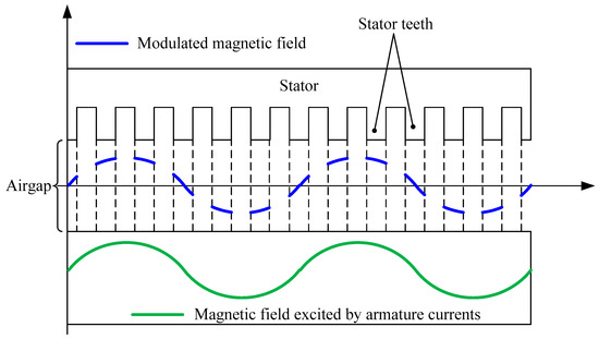
Figure 5.
Schematic diagram: Armature magnetic field modulated by stator teeth.
Finally, consider the field harmonics yielded when the magnetic field excited by the three-phase armature currents undergoes the FME of the RAT. As shown in Figure 6, the waveform of the modulated magnetic field differs from that in Figure 5 due to the difference in the number of RAT compared to stator teeth. Similarly, as per the magnetic gear effect, the PPN and the corresponding speed of the modulated field harmonics are governed by the following equations [56,57]:
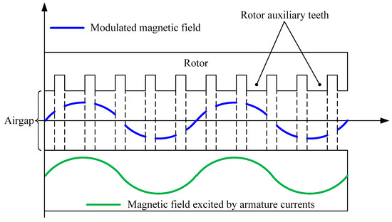
Figure 6.
Schematic diagram: Armature magnetic field modulated by rotor auxiliary teeth.
To achieve stable electromagnetic torque, the proposed RAT-PMVM must meet the following conditions [56]:
It can be found out from Table 2 that the modulated field harmonics in each group are with the same pole-pair number and synchronous speed. This means that stable torque can be achieved by the interaction among these effective field harmonics.
Table 2.
Effective field harmonics.
2.3. Working Principle Verification
To elucidate the working principle of the proposed RAT-PMVM, the radial airgap flux density resulting from field modulation effect is separately obtained for both PM and armature fields in transient magnetic field by using JMAG software (Version 23) for the 2D finite element method (FEM). Figure 7 illustrates the magnetic field distribution generated by V-shaped magnets. As can be seen, there are four flux envelope loops in the motor, indicating that the magnetic field generated by the ten-pole-pair magnets manifests as a two-pole-pair field under the combined action of the stator teeth and rotor auxiliary teeth. Figure 8 displays the radial airgap flux density waveform excited by V-shaped magnets and the corresponding FFT spectrum. Evidently, the waveform in Figure 8a exhibits non-sinusoidal characteristics attributable to the FME induced by stator teeth and RAT. As can be seen from Figure 8b, the spectrum contains multiple harmonics: the fundamental harmonic of PPN = 10 originates from the V-shaped PMs, whereas the field harmonic of PPN = 2 results from FME of the stator teeth. Since the pole-pair number of this field harmonic (PPN = 2) matches that of the three-phase armature windings (Pw = 2), and its rotational speed synchronizes with the armature current’s rotating magnetic field, stable torque is produced via interaction of this harmonic component with PPN = 2 with armature currents’ fundamental magnetic field (PPN = 2).
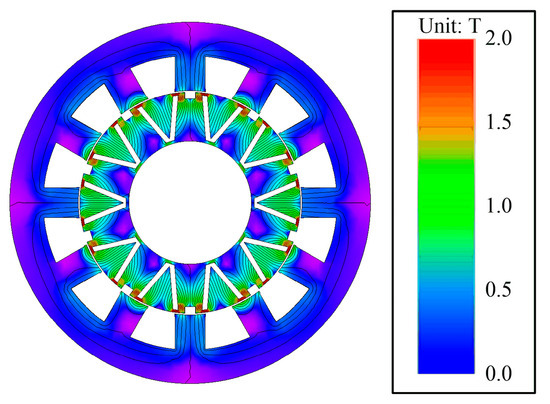
Figure 7.
Magnetic field distribution generated by V-shaped PMs.
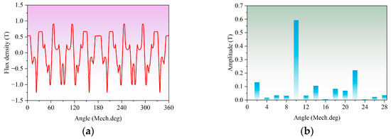
Figure 8.
Airgap flux density excited by V-shaped magnets: (a) waveform; (b) FFT spectrum.
Figure 9 exhibits the magnetic field distribution generated by three-phase armature currents. The number of flux envelopes also shows that the armature field manifests as a two-pole-pair field due to the stator and rotor auxiliary teeth, matching the pole-pair number of the three-phase armature windings exactly. Figure 10 displays the radial airgap flux density waveform excited by three-phase armature currents and the corresponding FFT spectrum. The waveform in Figure 10a exhibits significant non-sinusoidal distortion, confirming abundant harmonic content induced by FME generated through combined stator teeth and RAT interaction. As Figure 10b demonstrates, the fundamental magnetic field (PPN = 2) originates from the three-phase armature currents, whereas the field harmonic of PPN = 10 results from FME generated through combined stator teeth and RAT interaction. Since this harmonic’s pole-pair number (PPN = 10) matches that of the V-shaped magnets (Pr = 10) and its rotational speed synchronizes with the rotor, stable torque is produced through the interaction of this harmonic component with PPN = 10 with V-shaped PMs’ fundamental magnetic field (Pr = 10).
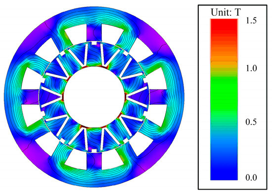
Figure 9.
Magnetic field distribution generated by 3-phase armature currents.
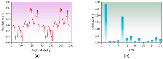
Figure 10.
Airgap flux density excited by 3-phase armature currents: (a) waveform; (b) FFT spectrum.
3. Influence of the Number of Rotor Auxiliary Teeth on Electromagnetic Performance
This section comparatively studies the influence of rotor auxiliary tooth count on the electromagnetic performance of the RAT-PMVM in a transient magnetic field by using 2D FEM. Figure 11 shows two rotor configurations with different rotor auxiliary tooth numbers. The rotor in Figure 11a has 10 rotor auxiliary teeth, while the rotor in Figure 11b has 20 rotor auxiliary teeth. For clarity, the PMVM with 20 rotor auxiliary teeth is denoted as multi-tooth RAT-PMVM (MRAT-PMVM), while that with 10 rotor auxiliary teeth is still designated as RAT-PMVM. As shown in Figure 12, two-dimensional finite element mesh models were established, with three layers of mesh generated in the airgap region for both models. Figure 12a shows the mesh model of the RAT-PMVM, with the number of elements and nodes being 27,086 and 14,777, respectively. Figure 12b shows the mesh model of the MRAT-PMVM, with the number of elements and nodes being 26,338 and 14,403, respectively. The average mesh quality provided by JMAG software (Version 23) is approximately 0.75 for both models (where the optimal mesh quality in this software corresponds to 1). The time step was set to approximately 0.192 ms for all simulations. Note that the basic parameters of the two motors except auxiliary tooth count are exactly the same as those in Table 1.
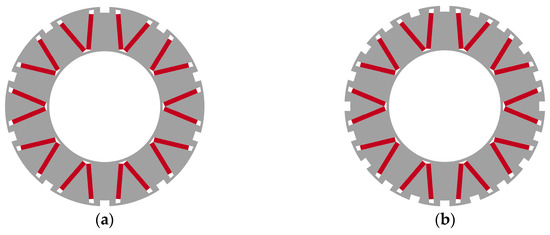
Figure 11.
Two rotor configurations with different rotor auxiliary tooth numbers: (a) 10 auxiliary teeth; (b) 20 auxiliary teeth.
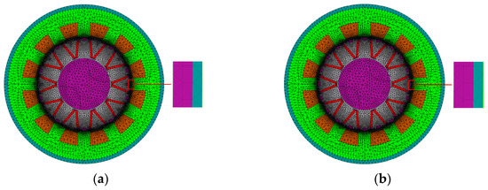
Figure 12.
Mesh models: (a) RAT-PMVM; (b) MRAT-PMVM.
3.1. Airgap Flux Density Comparison Between RAT-PMVM and MRAT-PMVM
Figure 13 compares the radial airgap flux density excited by three-phase armature currents in the RAT-PMVM and MRAT-PMVM. As shown, RAT-PMVM exhibits significantly higher amplitude in the primary torque-producing harmonic (PPN = 2) than MRAT-PMVM, while demonstrating marginally lower amplitude in the primary torque-contributing harmonic (PPN = 10). Figure 14 contrasts the radial airgap flux density produced by V-shaped magnets in the RAT-PMVM and MRAT-PMVM. The RAT-PMVM displays substantially higher amplitudes in both primary torque-producing harmonics (PPN = 2 and PPN = 10) compared to the MRAT-PMVM.
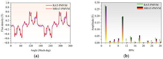
Figure 13.
Comparison of airgap flux density excited by 3-phase armature currents: (a) waveforms; (b) FFT spectra.
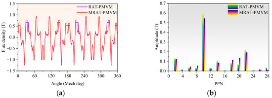
Figure 14.
Comparison of airgap flux density produced by V-shaped PMs: (a) waveforms; (b) FFT spectra.
3.2. Back-EMF Comparison Between RAT-PMVM and MRAT-PMVM
Figure 15 compares the Back-EMF of RAT-PMVM and MRAT-PMVM at the rated speed. As observed in Figure 15a, the Back-EMF period is consistently 20 ms for both PMVMs. Figure 15b demonstrates that RAT-PMVM exhibits a significantly higher fundamental Back-EMF amplitude than MRAT-PMVM, along with a lower total harmonic distortion (THD) of 15% versus 21.8% for MRAT-PMVM.
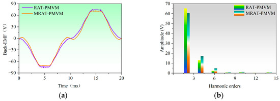
Figure 15.
Comparison of Back-EMF at 300 rpm: (a) waveforms; (b) FFT spectra.
3.3. Torque Performance Comparison Between RAT-PMVM and MRAT-PMVM
Figure 16 compares the cogging torque of RAT-PMVM and MRAT-PMVM. As evidenced, RAT-PMVM exhibits a cogging torque period of 3° versus 6° for MRAT-PMVM, with peak values measuring 0.16 Nm and 0.36 Nm, respectively. Notably, RAT-PMVM achieved a 55.6% reduction in peak value of cogging torque compared to MRAT-PMVM.
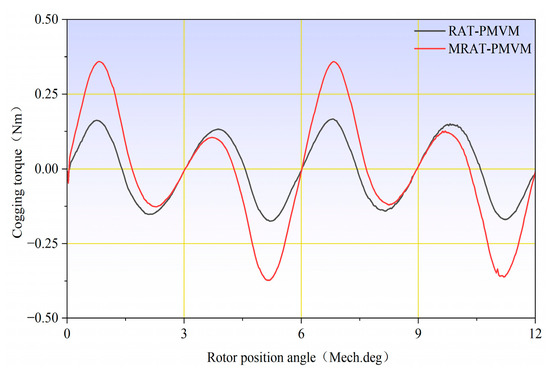
Figure 16.
Comparison of cogging torque.
Figure 17 compares the torque performance of the RAT-PMVM and MRAT-PMVM. Figure 17a displays the blocking torque curve during one electrical cycle under locked-rotor conditions (0 rpm) and rated current (I = 4 A), representing maximum torque output capability under the rated phase current. As can be seen, RAT-PMVM demonstrates superior torque output capability over MRAT-PMVM under the rated phase current. Figure 17b illustrates average torque versus current characteristics for both PMVMs. As current increases, the RAT-PMVM consistently generates higher average torque than the MRAT-PMVM.
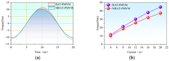
Figure 17.
Torque performance: (a) blocking torque; (b) average torque versus current.
Figure 18 compares the output torque of the RAT-PMVM and MRAT-PMVM at the rated current (I = 4 A) and the rated speed of 300 rpm. As can be seen, the RAT-PMVM achieves an average output torque of 11.32 Nm with 8.1% torque ripple ratio, outperforming the MRAT-PMVM’s average torque of 10.28 Nm and torque ripple ratio of 11.4%. Figure 19 and Figure 20 display the magnetic field distribution and current density distribution of the RAT-PMVM and MRAT-PMVM under rated conditions, respectively. Since the magnetic flux density corresponding to the knee point of the core material’s B-H curve is 1.5 T, and regions where the flux density exceeds this value are considered saturated. As can be seen from Figure 19, most areas of both motors remain unsaturated under rated conditions, except for the rotor tooth tips. As can be seen from Figure 20, the orange areas represent the regions with the highest current density, corresponding to a value of approximately 2.5 A/mm2. A current density below 4 A/mm2 ensures that the steady-state temperature rise of both motors under rated conditions remains within acceptable limits.
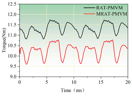
Figure 18.
Comparison of output torque RAT-PMVM and MRAT-PMVM at rated current and rated speed.
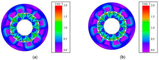
Figure 19.
Magnetic field distribution at rated conditions: (a) RAT-PMVM; (b) MRAT-PMVM.
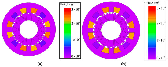
Figure 20.
Current density distribution at rated conditions: (a) RAT-PMVM; (b) MRAT-PMVM.
3.4. Comparison of Other Electromagnetic Performances Between RAT-PMVM and MRAT-PMVM
Table 3 compares additional electromagnetic performances between the RAT-PMVM and MRAT-PMVM. RAT-PMVM demonstrates superior efficiency and power factor relative to MRAT-PMVM, albeit with marginally higher losses.
Table 3.
Comparison of other electromagnetic performances between the RAT-PMVM and MRAT-PMVM.
4. Influence of the Position of Rotor Auxiliary Teeth on Electromagnetic Performance
The analysis in Section 3 reveals that RAT-PMVM demonstrates superior performance to MRAT-PMVM in Back-EMF, cogging torque, output torque, torque ripple, power factor, and efficiency. Consequently, this section investigates the influence of the position of rotor auxiliary teeth on electromagnetic performance, building upon RAT-PMVM. Figure 21a depicts the position of the rotor auxiliary teeth in RAT-PMVM, featured by each auxiliary tooth being aligned with a V-shaped PM. From the perspective of V-shaped PMs, the position is characterized by each V-shaped PM being aligned with an individual auxiliary tooth. It should be noted that the RAT-PMVM in this section maintains identical structure and parameters to the RAT-PMVM analyzed in Section 2 and Section 3. Figure 21b illustrates another position of the rotor auxiliary teeth, where each auxiliary tooth incorporates two magnets from distinct V-shaped PMs. Alternatively viewed, each V-shaped PM aligns with a rotor slot. For clarity, the RAT-PMVM with a V-shaped PM aligned with an auxiliary tooth is designated as V2T-PMVM, while the RAT-PMVM featuring a V-shaped PM aligned with a rotor slot is denoted as V2S-PMVM. Comparative studies between the V2T-PMVM and V2S-PMVM are carried out to analyze the influence of the position of rotor auxiliary teeth in a transient magnetic field by using 2D FEM with JMAG software (Version 23). Note that the basic parameters of the V2T-PMVM and V2S-PMVM are exactly the same as those in Table 1. As shown in Figure 22, two-dimensional finite element mesh models were established, with three layers of mesh generated in the airgap region. Figure 22a shows the mesh model of the V2T-PMVM, with the number of elements and nodes being 27,086 and 14,777, respectively. Figure 22b shows the mesh model of the V2S-PMVM, with the number of elements and nodes being 26,860 and 14,664, respectively. The average mesh quality provided by JMAG software (Version 23) is approximately 0.75 for both models. The time step was set to approximately 0.192 ms for all simulations.
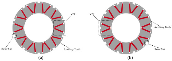
Figure 21.
Position of rotor auxiliary teeth: (a) V-shaped PM is aligned with an auxiliary tooth (V2T); (b) V-shaped PM is aligned with a rotor slot (V2S).

Figure 22.
Mesh models: (a) V2T-PMVM; (b) V2S-PMVM.
4.1. Airgap Flux Density Comparison Between V2T-PMVM and V2S-PMVM
Figure 23 compares the radial airgap flux density excited by three-phase armature currents in the V2T-PMVM and V2S-PMVM. As shown, V2S-PMVM exhibits significantly higher amplitude in the primary torque-producing harmonic (PPN = 2) than V2T-PMVM, while demonstrating marginally lower amplitude in the primary torque-contributing harmonic (PPN = 10). Figure 24 contrasts the radial airgap flux density excited by V-shaped magnets in the V2T-PMVM and V2S-PMVM. The V2S-PMVM presents substantially higher amplitudes in both primary torque-producing harmonics (PPN = 2 and PPN = 10) compared to the V2T-PMVM.
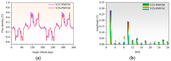
Figure 23.
Comparison of airgap flux density excited by 3-phase armature currents in V2T-PMVM and V2S-PMVM: (a) waveforms; (b) FFT spectra.
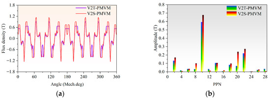
Figure 24.
Comparison of airgap flux density excited by V-shaped magnets in V2T-PMVM and V2S-PMVM: (a) waveforms; (b) FFT spectra.
4.2. Back-EMF Comparison Between V2T-PMVM and V2S-PMVM
Figure 25 shows the Back-EMF generated by the V2T-PMVM and V2S-PMVM at the rated speed of 300 rpm. It can be seen from Figure 25a that the Back-EMF period is 20 ms for both PMVMs. From Figure 25b, it can be seen that V2S-PMVM presents a significantly higher fundamental Back-EMF amplitude than V2T-PMVM, along with a lower THD of 14% versus 15% for V2T-PMVM.
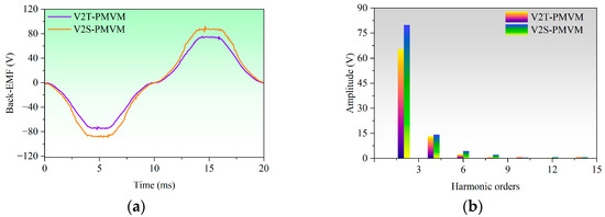
Figure 25.
Back-EMF comparison between V2T-PMVM and V2S-PMVM: (a) waveforms; (b) spectra.
4.3. Torque Performance Comparison Between V2T-PMVM and V2S-PMVM
Figure 26 compares the cogging torque between the V2T-PMVM and V2S-PMVM. Clearly, the V2T-PMVM exhibits a cogging torque period of 3° versus 6° for V2S-PMVM. Additionally, the V2T-PMVM exhibits a peak cogging torque of 0.16 Nm, substantially lower than the V2S-PMVM’s 0.34 Nm peak value.
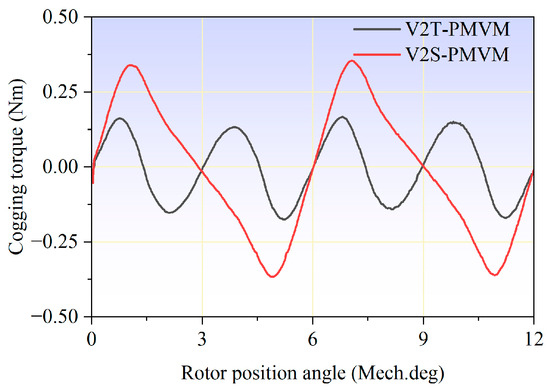
Figure 26.
Cogging torque comparison between V2S-PMVM and V2T-PMVM.
Figure 27 compares the torque performance of the V2T-PMVM and V2S-PMVM. Figure 27a displays the blocking torque curve during one electrical cycle under locked-rotor conditions (0 rpm) and rated current (I = 4 A), representing maximum torque output capability under the rated phase current. As can be seen, V2S-PMVM demonstrates superior torque output capability over V2T-PMVM under the rated phase current. Figure 27b illustrates average torque versus current characteristics for both PMVMs. As current increases, the V2S-PMVM consistently generates higher average torque than the V2T-PMVM.
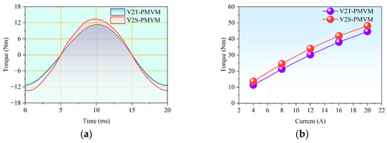
Figure 27.
Torque performance of V2S-PMVM and V2T-PMVM: (a) blocking torque; (b) average torque versus current.
Figure 28 compares the output torque of the V2T-PMVM and V2S-PMVM under rated current (I = 4 A) and rated speed (300 rpm). The V2T-PMVM achieves an average torque of 11.32 Nm with 8.1% torque ripple ratio, whereas the V2S-PMVM yields 13.53 Nm with a torque ripple ratio of 9.3%.
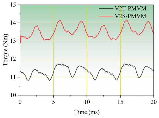
Figure 28.
Comparison of output torque V2T-PMVM and V2S-PMVM at rated current and rated speed.
Figure 29 and Figure 30 display the magnetic field distribution and current density distribution of the V2T-PMVM and V2S-PMVM under rated conditions, respectively. As can be seen from Figure 29, under rated conditions, both motors exhibit saturation primarily at the rotor tooth tips, while all other regions remain unsaturated. As can be seen from Figure 30, the maximum current density is approximately 2.5 A/mm2, which is well below 4 A/mm2. Therefore, the steady-state temperature rise remains within acceptable limits.
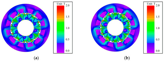
Figure 29.
Magnetic field distribution at rated condition: (a) V2T-PMVM; (b) V2S-PMVM.
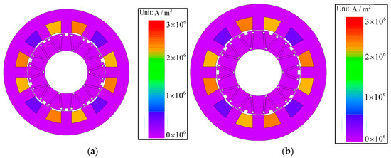
Figure 30.
Current density distribution at rated conditions: (a) V2T-PMVM; (b) V2S-PMVM.
4.4. Comparison of Other Electromagnetic Performances Between V2T-PMVM and V2S-PMVM
Table 4 compares other electromagnetic performances between the V2T-PMVM and V2S-PMVM. Although the V2S-PMVM exhibits marginally higher losses than the V2T-PMVM, it achieves superior efficiency and power factor.
Table 4.
Comparison of other electromagnetic performances between the V2T-PMVM and V2S-PMVM.
5. Influence of the Rotor Auxiliary Tooth Profile on Electromagnetic Performance
The analysis in Section 4 reveals that when V-shaped PMs align with rotor slots, the proposed RAT-PMVM denoted as V2S-PMVM demonstrates distinct advantages over the RAT-PMVM with V-shaped PMs aligned with rotor auxiliary teeth (denoted as V2T-PMVM) in Back-EMF, output torque, power factor, and efficiency. Therefore, this section investigates the impact of distinct rotor auxiliary tooth profiles on electromagnetic performance using V2S-PMVM as the baseline configuration. Figure 31 depicts the structural schematics of six distinct rotor auxiliary tooth profiles. The tooth profiles corresponding to Figure 31a–f are inverse-trapezoidal teeth (ITT), trapezoidal teeth (TT), T-shaped teeth (TST), dovetail teeth (DT), stepped teeth (ST), and combined teeth (CT), respectively. It should be noted that a combined teeth profile comprises an inverse-trapezoidal tooth integrated with a trapezoidal tooth. To facilitate subsequent analysis, the RAT-PMVMs corresponding to these tooth profiles are denoted as follows:
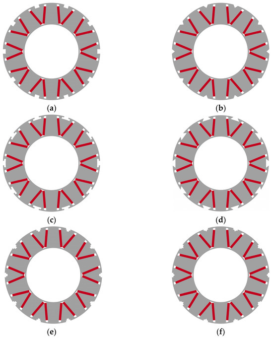
Figure 31.
Rotor auxiliary tooth profiles: (a) inverse-trapezoidal teeth (ITT); (b) trapezoidal teeth (TT); (c) T-shaped teeth (TST); (d) dovetail teeth (DT); (e) stepped teeth (ST); (f) combined teeth (CT).
- ITT-PMVM: RAT-PMVM with inverse-trapezoidal teeth;
- TT-PMVM: RAT-PMVM with trapezoidal teeth;
- TST-PMVM: RAT-PMVM with T-shaped teeth;
- DT-PMVM: RAT-PMVM with dovetail teeth;
- ST-PMVM: RAT-PMVM with stepped teeth;
- CT-PMVM: RAT-PMVM with combined teeth.
This section comparatively analyzes six RAT-PMVMs with diverse rotor auxiliary tooth profiles in a transient magnetic field by using 2D FEM in JMAG software (Version 23), examining their influence on electromagnetic performance. Note that the basic parameters of these six RAT-PMVMs are identical to those in Table 1. The two-dimensional finite element mesh models with three layers of airgap meshes are shown in Figure 32. The average mesh quality is approximately 0.75 for all models. The time step was set to approximately 0.192 ms for all simulations.
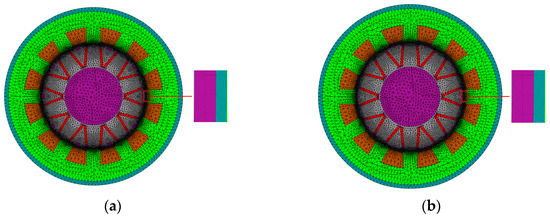
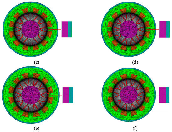
Figure 32.
Mesh models: (a) ITT-PMVM; (b) TT-PMVM; (c) TST-PMVM; (d) DT-PMVM; (e) ST-PMVM; (f) CT-PMVM.
5.1. Airgap Flux Density Comparison Among the Six PMVMs
Figure 33 and Figure 34 comparatively analyze the radial airgap flux density excited by three-phase armature currents and V-shaped PMs, respectively, across the six RAT-PMVMs with diverse rotor auxiliary tooth profiles. As evidenced by these two figures, TT-PMVM exhibits higher amplitudes in the predominantly torque-producing harmonics (PPN = 2 and PPN = 10) for airgap flux densities produced by three-phase armature currents and V-shaped magnets, compared to the other five RAT-PMVMs with distinct rotor auxiliary tooth profiles.
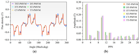
Figure 33.
Comparison of airgap flux density excited by 3-phase armature currents in the six RAT-PMVMs: (a) waveforms; (b) FFT spectra.
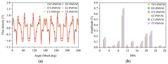
Figure 34.
Comparison of airgap flux density produced by V-shaped PMs in the six RAT-PMVMs: (a) waveforms; (b) FFT spectra.
5.2. Back-EMF Comparison Among the Six PMVMs
Figure 35 compares Back-EMF across the six RAT-PMVMs with diverse rotor auxiliary tooth profiles at 300 rpm. As Figure 35a demonstrates, the TT-PMVM achieves the highest Back-EMF amplitude. Figure 35b reveals the following THD values: TST-PMVM (10.5%), DT-PMVM (12.5%), TT-PMVM (13.5%), IT-PMVM (14.0%), CT-PMVM (14.1%), and ST-PMVM (14.2%).
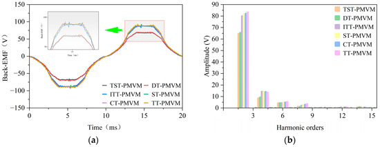
Figure 35.
Back-EMF comparison across the six RAT-PMVMs with diverse rotor auxiliary tooth profiles: (a) waveforms; (b) spectra.
5.3. Torque Performance Comparison Among the Six PMVMs
Figure 36 compares cogging torque across six RAT-PMVMs with distinct auxiliary tooth profiles. As observed, TST-PMVM exhibits a cogging torque period of 4°, while the other five RAT-PMVMs share a period of 6°. Furthermore, the peak values of cogging torque are as follows: 0.28 Nm for ST-PMVM, 0.28 Nm for CT-PMVM, 0.32 Nm for TT-PMVM, 0.34 Nm for IT-PMVM, 0.83 Nm for DT-PMVM, and 0.84 Nm for TST-PMVM. Figure 37 compares the torque performance across six RAT-PMVMs with distinct auxiliary tooth profiles. Figure 37a displays the blocking torque curve during one electrical cycle under locked-rotor conditions (0 rpm) and rated current (I = 4 A). Clearly, TT-PMVM demonstrates superior torque output capability over the other five RAT-PMVMs under the rated phase current. Figure 37b illustrates average torque versus current characteristics for the six RAT-PMVMs. As current increases, the TT-PMVM consistently generates higher average torque than the other five RAT-PMVMs. Figure 38 compares output torque performance across six RAT-PMVMs with distinct auxiliary tooth profiles at the rated current (I = 4 A) and the rated speed of 300 rpm. The TT-PMVM achieves the highest average torque (14.19 Nm) with a ripple ratio of 11%.
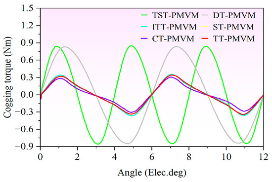
Figure 36.
Cogging torque comparison across the six RAT-PMVMs with diverse rotor auxiliary tooth profiles.
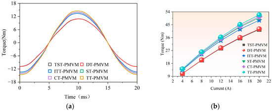
Figure 37.
Comparison of torque performance across six RAT-PMVMs with distinct auxiliary tooth profiles: (a) blocking torque; (b) average torque versus current.
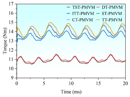
Figure 38.
Comparison of output torque across six RAT-PMVMs with distinct auxiliary tooth profiles at rated current and rated speeds.
Figure 39 and Figure 40 display the magnetic field distribution and current density distribution of the six PMVMs under rated conditions, respectively. Based on the flux lines, leakage flux is observed at the stator slot openings of all six motors, with all six motors exhibiting leakage flux to a similar extent. From the magnetic flux density contours, the majority of the regions remain unsaturated except for the rotor tooth tips, and the extent of the unsaturated areas is also comparable across all six motors. As can be seen from Figure 40, all six motors exhibit minimal variation in their current density distributions. With the maximum current density remaining below 4 A/mm2, the steady-state temperature rise remains within acceptable limits.
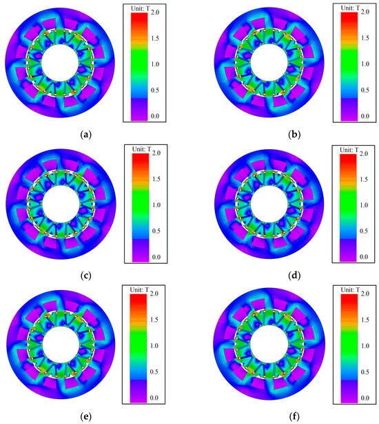
Figure 39.
Magnetic field distribution at rated conditions: (a) ITT-PMVM; (b) TT-PMVM; (c) TST-PMVM; (d) DT-PMVM; (e) ST-PMVM; (f) CT-PMVM.
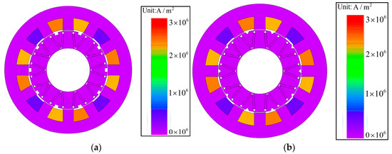
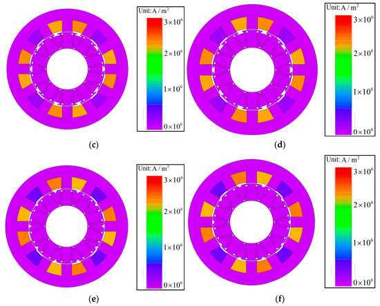
Figure 40.
Current density distribution at rated conditions: (a) ITT-PMVM; (b) TT-PMVM; (c) TST-PMVM; (d) DT-PMVM; (e) ST-PMVM; (f) CT-PMVM.
5.4. Comparison of Other Electromagnetic Performances Among the Six PMVMs
Table 5 compares the other electromagnetic performances of six RAT-PMVMs with distinct auxiliary tooth profiles. Besides Back-EMF and output torque, the TT-PMVM demonstrates superior efficiency and power factor compared to the other five RAT-PMVMs.
Table 5.
Comparison of other electromagnetic performance across six RAT-PMVMs with distinct auxiliary tooth profiles.
6. Multi-Objective Optimization
The foregoing results demonstrate that the TT-PMVM achieves enhanced Back-EMF, output torque, efficiency, and power factor through comparatively analyzing the influence of the number, position, and profile of rotor auxiliary teeth. However, the TT-PMVM suffers from large torque ripples. Consequently, a multi-objective genetic algorithm is employed to optimize the TT-PMVM by using JMAG software (Version 23), targeting a simultaneous reduction in torque ripples and enhancement of the output torque, power factor, and efficiency.
Figure 41 illustrates the geometric parameter schematic for multi-objective optimization, while Table 6 details corresponding parameter ranges.
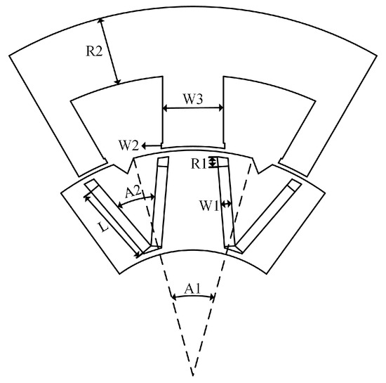
Figure 41.
Schematic diagram of the geometric parameters in TT-PMVM: A1: the central angle of the auxiliary tooth; A2: angle of V-shaped PM; L: length of PM; R1: length of magnetic barrier; R2: thickness of stator yoke; W1: thickness of PM; W2: height of stator tooth shoe; W3: width of stator tooth.
Table 6.
Geometric parameter ranges for multi-objective optimization.
The optimization objectives are defined as follows:
where Trip denotes the torque ripple ratio, Tave represents average torque, EFF signifies efficiency, and PF indicates power factor.
The expression of Trip [58] is the following:
The expression of Tave [59] is the following:
The expression of EFF [60] is the following:
where corresponds to the mechanical angular speed of the rotor; represents the copper loss; represents the total iron loss; represents the permanent magnet hysteresis loss.
The expression of PF [61] is the following:
where E0 denotes the RMS value of Back-EMF; represents the RMS value of phase current; Ra signifies the per-phase winding resistance; corresponds to the mechanical angular speed of the rotor; Lq stands for q-axis inductance.
Figure 42 illustrates the procedure for multi-objective optimization employed in the JMAG software (Version 23). First, the optimization objectives are set as torque ripple ratio, average torque, efficiency, and power factor, as expressed in Equation (11). The optimization variables are defined as the geometric parameters listed in Table 6. Next, the key task is to establish a parametric simulation model in JMAG software (Version 23). The optimization objectives are configured according to Equation (11), and the variation ranges of the geometric parameters are set based on Table 6. Then, the genetic algorithm is selected in JMAG for optimization. Afterwards, the optimization process is executed, once all configurations are completed. Finally, the results are analyzed to determine the optimal solution.
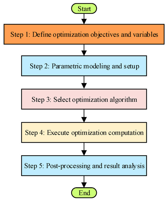
Figure 42.
Flowchart of the multi-objective optimization process using JMAG software (Version 23).
Figure 43 presents the optimization results for TT-PMVM. The result indicated by the red arrow satisfies the optimization objectives defined in Equation (11). Consequently, the corresponding geometric parameters are selected as the optimal configuration for TT-PMVM, as listed in Table 7. As can be seen from the table, the value of R1 has been reduced to 0.9 mm after optimization. Such a small distance may pose a challenge for the high-precision assembly of future prototypes. Figure 44 compares the Back-EMF of the TT-PMVM at 300 rpm before and after optimization. The optimized waveform in Figure 44a exhibits increased amplitude. Corresponding harmonic spectra in Figure 44b demonstrate reduced THD from 13.5% to 11.9%.
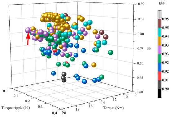
Figure 43.
Optimization results for TT-PMVM.
Table 7.
Geometric parameters before and after optimization for TT-PMVM.
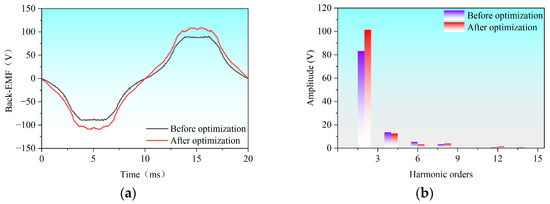
Figure 44.
Back-EMF of TT-PMVM before and after optimization at 300 rpm: (a) waveforms; (b) spectra.
Figure 45 compares torque performance of TT-PMVM before and after optimization. Figure 45a displays the blocking torque curve during one electrical cycle under locked-rotor conditions (0 rpm) and rated current (I = 4 A). Clearly, the optimized TT-PMVM exhibits increased torque output capability. Figure 45b illustrates the average torque versus current characteristics of TT-PMVM before and after optimization. As the current increases, the optimized TT-PMVM generates higher average torque. Figure 46 compares the rated output torque of the TT-PMVM before and after optimization. The optimized TT-PMVM demonstrates a 27.3% increase in average torque (14.19 Nm → 18.06 Nm), while the torque ripple ratio decreases by 31.8% (11.0% → 7.5%).
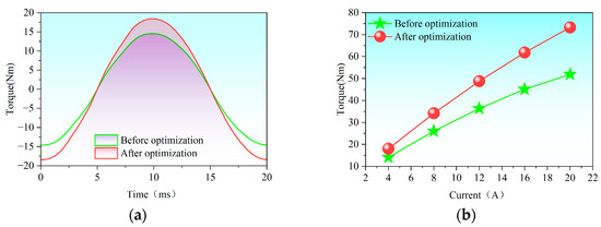
Figure 45.
Torque performance of TT-PMVM before and after optimization: (a) blocking torque; (b) average torque versus current.
Figure 46.
The rated output torque of TT-PMVM before and after optimization.
Figure 47 and Figure 48 display the magnetic field distribution and current density distribution of the TT-PMVM before and after optimization under rated conditions, respectively. As can be seen from Figure 47, the saturation level of the TT-PMVM under rated conditions is comparable before and after optimization. However, by comparing the number of leakage flux lines at the stator slots, it is observed that the leakage flux is reduced after optimization. As can be seen from Figure 48, the maximum current density of the optimized motor does not exceed 4 A/mm2 under rated conditions. Thus, the steady-state temperature rise remains within acceptable limits after optimization.
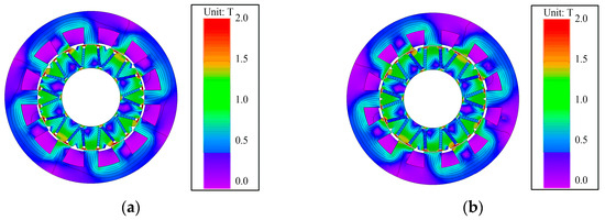
Figure 47.
Magnetic field distribution at rated conditions: (a) before optimization; (b) after optimization.
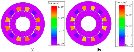
Figure 48.
Current density distribution at rated conditions: (a) before optimization; (b) after optimization.
Table 8 compares the other electromagnetic performances of the TT-PMVM before and after optimization. Beyond output torque enhancement and torque ripple reduction, the efficiency (EFF) of the optimized TT-PMVM increases from 92.2% to 93.0% (+0.8%), while the power factor (PF) improves from 0.73 to 0.81 (+11.0%).
Table 8.
Comparison of the other electromagnetic performances of the TT-PMVM before and after optimization.
7. Conclusions
Based on the foregoing analysis presented in this paper, the following conclusions are drawn regarding the proposed permanent magnet vernier motor with rotor auxiliary teeth (RAT-PMVM):
- Structural Superiority of TT-PMVM: Comparative analysis of the number, position, and tooth profile of rotor auxiliary teeth definitively establishes the TT-PMVM as optimal. This configuration significantly enhances electromagnetic performance, yielding a 25.4% increase in output torque (from 11.32 Nm to 14.19 Nm), a 4.2% improvement in efficiency (from 88.5% to 92.2%), and a 15.7% increase in power factor (from 0.60 to 0.71) compared to the initial RAT-PMVM in Figure 1.
- Effective Torque Ripple Mitigation via Optimization: While the TT-PMVM offered substantial performance gains, it suffered from large torque rippling. Application of a multi-objective genetic algorithm successfully addressed this issue. After optimization, the TT-PMVM achieved a remarkable 27.3% further increase in average torque (to 18.06 Nm) alongside a significant 31.8% reduction in torque ripple ratio (from 11.0% to 7.5%).
- Overall Performance Enhancement: The multi-objective optimization simultaneously elevated the efficiency and power factor of the TT-PMVM. After optimization for the TT-PMVM, the stator and rotor cores exhibit a lower saturation level, the maximum current density does not exceed 4 A/mm2, leakage flux is significantly reduced, efficiency increased by 0.8% (to 93.0%), and power factor improved by 11.0% (to 0.81), demonstrating the effectiveness of the holistic optimization approach.
- Future Work and Challenges: The influence of different slot–pole combinations on the performance of the TT-PMVM will be studied; the risk of demagnetization will be analyzed; the mechanical strength of the rotor will also be investigated; an experimental prototype will be machined and tested to validate the simulation results; the application of the TT-PMVM will be explored in industrial robots, assessing its performance against application-specific requirements like torque density, fault tolerance, or cost-effectiveness. The value of R1 has been reduced to 0.9 mm after optimization. Such a small distance may pose a challenge for the high-precision assembly of future prototypes. Additionally, how to secure and assemble the magnets according to the optimized dimensions without compromising the electromagnetic performance may also pose a challenge.
Author Contributions
Conceptualization, Y.S. and W.Z.; methodology, W.Z. and Q.L.; software, W.Z. and Q.L.; validation, Y.S. and W.Z.; formal analysis, H.L. and J.W.; investigation, W.Z.; resources, Y.L.; data curation, W.Z.; writing—original draft preparation, W.Z.; writing—review and editing, Y.S. and J.W.; visualization, W.Z. and Q.L.; supervision, Y.S. and H.L.; project administration, Y.S.; funding acquisition, Y.S. All authors have read and agreed to the published version of the manuscript.
Funding
This work was supported in part by the Tianchi Talent Projects of Xinjiang Urumqi Autonomous Region of China under grants 51052401512 and 5105240151s and in part by the Research Startup Fund for Excellent Talents at Xinjiang University under grants 620323005 and 620323007.
Data Availability Statement
The original contributions presented in this study are included in this article. Further inquiries can be directed to the corresponding author.
Conflicts of Interest
Yaogang Liu is employed by Integrated Electronic Systems Lab Co., Ltd.. The authors declare that the research was conducted in the absence of any commercial or financial relationships that could be construed as a potential conflict of interest.
References
- Sharma, P.; Sashidhar, S. Permanent Magnet Vernier Generator with Surface Ferrite Magnets for a Direct-Drive Wind Generator. In Proceedings of the 2022 International Conference on Electrical Machines (ICEM), Valencia, Spain, 5–8 September 2022. [Google Scholar]
- Cheng, M.; Han, P.; Du, Y.; Wen, H.; Li, X. A Tutorial on General Air-Gap Field Modulation Theory for Electrical Machines. IEEE J. Emerg. Sel. Top. Power Electron. 2022, 10, 1712–1732. [Google Scholar] [CrossRef]
- Yu, Y.; Chai, F.; Pei, Y.; Doppelbauer, M.; Lee, C.H.T. Comparative Study of Loss Characteristic Between Permanent Magnet Synchronous Machine and Vernier Machine for In-Wheel Direct Drive. IEEE Trans. Transp. Electrific. 2025, 11, 2035–2048. [Google Scholar] [CrossRef]
- Yu, Y.; Pei, Y.; Chai, F.; Doppelbauer, M. Performance Comparison Between Permanent Magnet Synchronous Motor and Vernier Motor for In-Wheel Direct Drive. IEEE Trans. Ind. Electron. 2023, 70, 7761–7772. [Google Scholar] [CrossRef]
- Almandoz, G.; Gómez, I.; Ugalde, G.; Poza, J.; Escalada, A.J. Study of Demagnetization Risk in PM Machines. IEEE Trans. Ind. Appl. 2019, 55, 3490–3500. [Google Scholar] [CrossRef]
- Padinharu, D.K.K.; Li, G.J.; Zhu, Z.Q.; Clark, R.; Thomas, A.; Azar, Z. Permanent Magnet Vernier Machines for Direct-Drive Offshore Wind Power: Benefits and Challenges. IEEE Access 2022, 10, 20652–20668. [Google Scholar] [CrossRef]
- Yue, Y.; Jia, S.; Liang, D. New Topologies of High Torque Density Machine Based on Magnetic Field Modulation Principle. CES Trans. Electr. Mach. Syst. 2023, 7, 1–10. [Google Scholar] [CrossRef]
- Zhu, X.; Lee, C.H.T.; Chan, C.C.; Xu, L.; Zhao, W. Overview of Flux-Modulation Machines Based on Flux-Modulation Principle: Topology, Theory, and Development Prospects. IEEE Trans. Transp. Electrific. 2020, 6, 612–624. [Google Scholar] [CrossRef]
- Zhao, Y.; Li, D.; Ren, X.; Zou, T.; Qu, R. Design Trade-Off Between Torque Density and Power Factor in Surface-Mounted PM Vernier Machines Through Closed-Form Per-Unit Equations. IEEE Trans. Ind. Appl. 2023, 59, 3265–3277. [Google Scholar] [CrossRef]
- Liu, G.; Chen, M.; Zhao, W.; Chen, Q.; Zhao, W. Design and Analysis of Five-Phase Fault-Tolerant Interior Permanent-Magnet Vernier Machine. IEEE Trans. Appl. Supercond. 2016, 26, 1–5. [Google Scholar] [CrossRef]
- Hsieh, M.; Chang, C.; Huynh, T.; Dorrell, D. Design and Analysis of Consequent-Pole Permanent Magnet Vernier Motor with Cancellation of Even-Order Harmonics. IEEE Trans. Magn. 2023, 59, 1–6. [Google Scholar] [CrossRef]
- Jiang, J.; Niu, S.; Li, Z.; Dai, L.; Wu, W.; Chan, W. Design of a Novel Dual-PM Vernier Machine for High-Torque Direct-Drive Application. IEEE Trans. Transp. Electrific. 2025, 11, 6107–6118. [Google Scholar] [CrossRef]
- Xiang, Z.; Pu, W.; Zhu, X.; Quan, L. Design and Analysis of a V-Shaped Permanent Magnet Vernier Motor for High Torque Density. CES Trans. Electr. Mach. Syst. 2022, 6, 20–28. [Google Scholar] [CrossRef]
- Ghods, M.; Faiz, J.; Bazrafshan, M.; Gorginpour, H.; Toulabi, M. A Mathematical and Dynamical Model for Analyzing H-Shaped PM Vernier Motor for Electric Motorcycle Mid-Drive Applications. IEEE Trans. Energy Convers. 2025, 40, 529–543. [Google Scholar] [CrossRef]
- Ghods, M.; Faiz, J.; Bazrafshan, M.; Gorginpour, H.; Toulabi, M. Design of an L-Shaped Array Vernier Permanent Magnet Machine for Unmanned Aerial Vehicle Propulsion Using a Schwarz–Christoffel Mapping-Based Equivalent Magnetic Network Model. IEEE Trans. Ind. Electron. 2024, 71, 237–249. [Google Scholar] [CrossRef]
- Huang, H.; Li, D.; Qu, R.; Gao, X.; Han, B. Design and Analysis of T-Shaped Consequent Pole Dual PM Vernier Machines with Differential Magnetic Network Method. IEEE J. Emerg. Sel. Top. Power Electron. 2022, 10, 4546–4555. [Google Scholar] [CrossRef]
- Yang, F.; Xie, Y.; Cai, W.; Wang, L.; Ye, B.; He, S. The Magnetic Field Analytical Calculation of Permanent Magnet Vernier Synchronous Machine with Saddle-Shaped Permanent Magnets. IEEE Trans. Magn. 2023, 59, 1–13. [Google Scholar] [CrossRef]
- Allahyari, A.; Bostanci, E.; Mahmoudi, A. High-Performance Vernier Machines with Halbach Array Permanent Magnets for Direct Drive Applications. Machines 2023, 11, 525. [Google Scholar] [CrossRef]
- Zhang, Y.; Zhao, Y.; Li, D.; Qu, R. A Novel High Torque Density Spoke-Array Permanent Magnets Vernier Machine with Magnets Bridge. IEEE Trans. Ind. Appl. 2025, 61, 6336–6346. [Google Scholar] [CrossRef]
- Zou, T.; Li, D.; Chen, C.; Qu, R.; Jiang, D. A Multiple Working Harmonic PM Vernier Machine with Enhanced Flux-Modulation Effect. IEEE Trans. Magn. 2018, 54, 1–5. [Google Scholar] [CrossRef]
- Ghods, M.; Faiz, J.; Gorginpour, H. Design and Evaluation of a Consequent Pole K-Shaped Permanent Magnet Motor for Outboard Application using a Hybrid Mathematical Model. CES Trans. Electr. Mach. Syst. 2024, 8, 379–393. [Google Scholar] [CrossRef]
- Fang, L.; Li, D.; Ren, X.; Qu, R. A Novel Permanent Magnet Vernier Machine with Coding-Shaped Tooth. IEEE Trans. Ind. Electron. 2022, 69, 6058–6068. [Google Scholar] [CrossRef]
- Liu, G.; Guan, R.; Xu, L. Unequal Stator Modulated Teeth Structure to Reduce Electromagnetic Vibration in Permanent Magnet Vernier Machine. IEEE Trans. Ind. Electron. 2023, 70, 12036–12047. [Google Scholar] [CrossRef]
- Xie, K.; Li, D.; Qu, R.; Gao, Y. A Novel Permanent Magnet Vernier Machine with Halbach Array Magnets in Stator Slot Opening. IEEE Trans. Magn. 2017, 53, 1–5. [Google Scholar] [CrossRef]
- He, Z.; Xiao, F.; Du, Y.; Zhu, X. Comparison of Permanent Magnet Vernier Motors with Evenly and Unevenly Distributed Modulation Teeth. IEEE Trans. Magn. 2023, 59, 1–5. [Google Scholar] [CrossRef]
- Zhou, H.; Tao, W.; Zhou, C. Consequent Pole Permanent Magnet Vernier Machine with Asymmetric Air-Gap Field Distribution. IEEE Access 2019, 7, 109340–109348. [Google Scholar] [CrossRef]
- Zou, T.; Li, D.; Qu, R.; Jiang, D.; Li, J. Advanced High Torque Density PM Vernier Machine with Multiple Working Harmonics. IEEE Trans. Ind. Appl. 2017, 53, 5295–5304. [Google Scholar] [CrossRef]
- Wang, T.; Zhu, X.; Xiang, Z.; Fan, D.; Quan, L. Torque Ripple Suppression of a Permanent Magnet Vernier Motor From Perspective of Shifted Air-Gap Permeance Distribution. IEEE Trans. Magn. 2022, 58, 1–6. [Google Scholar] [CrossRef]
- Zhou, H.; Jiang, G.; Ye, C.; Li, G. Design and Analysis of a Novel Asymmetric-Stator-Pole Dual-PM Vernier Machine. IEEE Trans. Energy Convers. 2025, 40, 2307–2318. [Google Scholar] [CrossRef]
- Ahmad, H.; Ro, J. Analysis and Design Optimization of V-Shaped Permanent Magnet Vernier Motor for Torque Density Improvement. IEEE Access 2021, 9, 13542–13552. [Google Scholar] [CrossRef]
- Zhao, Y.; Li, D.; Ren, X.; Qu, R.; Sun, J.; Yu, P. Optimal Pole Ratio of Spoke-type Permanent Magnet Vernier Machines for Direct-drive Applications. CES Trans. Electr. Mach. Syst. 2022, 6, 454–464. [Google Scholar] [CrossRef]
- Xu, L.; Zhao, W.; Liu, G.; Song, C. Design Optimization of a Spoke-Type Permanent-Magnet Vernier Machine for Torque Density and Power Factor Improvement. IEEE Trans. Veh. Technol. 2019, 68, 3446–3456. [Google Scholar] [CrossRef]
- Zhou, Y.; Li, H.; Ren, N.; Xue, Z.; Wei, Y. Analytical Calculation and Optimization of Magnetic Field in Spoke-Type Permanent-Magnet Machines Accounting for Eccentric Pole-Arc Shape. IEEE Trans. Magn. 2017, 53, 1–7. [Google Scholar] [CrossRef]
- Lin, Q.; Niu, S.; Fu, W. Design and Optimization of a Dual-Permanent-Magnet Vernier Machine with a Novel Optimization Model. IEEE Trans. Magn. 2020, 56, 1–5. [Google Scholar] [CrossRef]
- Tsunata, R.; Takemoto, M. Skewing Technology for Permanent Magnet Synchronous Motors: A Comprehensive Review and Recent Trends. IEEE Open J. Ind. Electron. Soc. 2024, 5, 1251–1273. [Google Scholar] [CrossRef]
- Zhang, Z.; Wang, P.; Hua, W.; Zhang, T.; Wang, G.; Hu, M. Comprehensive Investigation and Evaluation of Cogging Torque Suppression Techniques of Flux-Switching Permanent Magnet Machines. IEEE Trans. Transp. Electrific. 2023, 9, 3894–3907. [Google Scholar] [CrossRef]
- Wan, X.; Yang, S.; Li, Y.; Shi, Y.; Lou, J. Minimization of Cogging Torque for V-Type IPMSM by the Asymmetric Auxiliary Slots on the Rotor. IEEE Access 2022, 10, 89428–89436. [Google Scholar] [CrossRef]
- Gao, J.; Wang, G.; Liu, X.; Zhang, W.; Huang, S.; Li, H. Cogging Torque Reduction by Elementary-Cogging-Unit Shift for Permanent Magnet Machines. IEEE Trans. Magn. 2017, 53, 1–5. [Google Scholar] [CrossRef]
- Alsuwian, T. Six-Phase Fully Coreless Axial-Flux Permanent-Magnet Generator: Design, Fabrication, and Performance Analysis. IEEE Access 2025, 13, 22647–22655. [Google Scholar] [CrossRef]
- Aslan, B.; Semail, E.; Korecki, J.; Lagranger, J. Slot/pole combinations choice for concentrated multiphase machines dedicated to mild-hybrid applications. In Proceedings of the 37th Annual Conference of the IEEE Industrial Electronics Society, Melbourne, VIC, Australia, 7–10 November 2011. [Google Scholar]
- Kim, J.; Li, Y.; Cetin, E.; Sarlioglu, B. Influence of Rotor Tooth Shaping on Cogging Torque of Axial Flux-Switching Permanent Magnet Machine. IEEE Trans. Ind. Appl. 2019, 55, 1290–1298. [Google Scholar] [CrossRef]
- Wanjiku, J.; Khan, M.; Barendse, P.; Pillay, P. Influence of Slot Openings and Tooth Profile on Cogging Torque in Axial-Flux PM Machines. IEEE Trans. Ind. Electron. 2015, 62, 7578–7589. [Google Scholar] [CrossRef]
- Xiang, P.; Yan, L.; Xiao, H.; He, X.; Du, N. Development of a Novel Radial-Flux Machine with Enhanced Torque Profile Employing Quasi-Cylindrical PM Pattern. IEEE Trans. Energy Convers. 2023, 38, 2772–2783. [Google Scholar] [CrossRef]
- Xiao, L.; Li, J.; Qu, R.; Lu, Y.; Zhang, R.; Li, D. Cogging Torque Analysis and Minimization of Axial Flux PM Machines with Combined Rectangle-Shaped Magnet. IEEE Trans. Ind. Appl. 2017, 53, 1018–1027. [Google Scholar] [CrossRef]
- Yan, F.; Ji, J.; Ling, Z.; Sun, Y.; Zhao, W. Magnets Shifting Design of Dual PM Excited Vernier Machine for High-Torque Application. Chin. J. Electr. Eng. 2022, 8, 90–101. [Google Scholar] [CrossRef]
- Huang, H.; Li, D.; Ren, X.; Qu, R. Analysis and Reduction Methods of Cogging Torque in Dual PM Vernier Machines with Unevenly Distributed Split Teeth. IEEE Trans. Ind. Appl. 2022, 58, 4637–4647. [Google Scholar] [CrossRef]
- Nakagawa, H.; Sato, T.; Todaka, T. Development of a New Stator Module Type Vernier Motor utilizing Amorphous Cut Core. In Proceedings of the 2018 IEEE International Magnetic Conference (Intermag), Singapore, 23–27 April 2018. [Google Scholar]
- Yu, Y.; Xie, S.; Chai, F.; Pei, Y.; Zhang, X.; Lee, C.H.T. Analysis and Suppression of Core and PM Losses in Fractional-Slot Permanent Magnet Vernier Machine and PMSM for in-Wheel Application. IEEE Trans. Ind. Appl. 2025, 61, 6305–6316. [Google Scholar] [CrossRef]
- Xu, L.; Sun, Z.; Zhao, W. Stator Core Loss Analysis and Suppression of Permanent Magnet Vernier Machines. IEEE Trans. Ind. Electron. 2023, 70, 12155–12167. [Google Scholar] [CrossRef]
- Zhu, X.; Zhao, M.; Cao, L.; Wang, H.; Zhao, C.; Lee, C.H.T. Harmonic Loss Reduction of Fractional Slot Concentrated Winding Permanent-Magnet Vernier Motor with Different Stator-Modular Designs. IEEE Trans. Ind. Appl. 2025, 61, 56–66. [Google Scholar] [CrossRef]
- Ji, J.; Jian, C.; Zhao, W.; Lin, Z.; Zeng, Y.; Li, Z. Reduction of Losses in Dual-permanent-magnet-excited Vernier Machine by Segmented Stator for Electric Aircraft. IET Electr. Power Appl. 2024, 18, 1740–1751. [Google Scholar] [CrossRef]
- Xu, L.; Liu, G.; Zhao, W.; Yang, X.; Cheng, R. Hybrid Stator Design of Fault-Tolerant Permanent-Magnet Vernier Machines for Direct-Drive Applications. IEEE Trans. Ind. Electron. 2017, 64, 179–190. [Google Scholar] [CrossRef]
- Xu, L.; Zhao, W.; Li, R.; Niu, S. Analysis of Rotor Losses in Permanent Magnet Vernier Machines. IEEE Trans. Ind. Electron. 2022, 69, 1224–1234. [Google Scholar] [CrossRef]
- Li, X.; Lu, K.; Zhao, Y.; Chen, Y.; Chen, D.; Yi, P.; Hua, W. Incorporating Harmonic-Analysis-Based Loss Minimization Into MPTC for Efficiency Improvement of FCFMPM Motor. IEEE Trans. Ind. Electron. 2023, 70, 6540–6550. [Google Scholar] [CrossRef]
- Qu, R.; Li, D.; Wang, J. Relationship Between Magnetic Gears and Vernier Machines. In Proceedings of the 2011 International Conference on Electrical Machines and Systems, Beijing, China, 20–23 August 2011. [Google Scholar]
- Jian, L.; Shi, Y.; Liu, C.; Xu, G.; Gong, X.; Chan, C.C. A Novel Dual-Permanent-Magnet-Excited Machine for Low-Speed Large-Torque Applications. IEEE Trans. Magn. 2013, 49, 2381–2384. [Google Scholar] [CrossRef]
- Yu, L.; Chai, F.; Pei, Y.; Chen, L. Comparisons of Torque Performance in Surface-Mounted PM Vernier Machines with Different Stator Tooth Topologies. IEEE Trans. Ind. Appl. 2019, 55, 3671–3684. [Google Scholar] [CrossRef]
- Zhu, Z.Q.; Wu, Z.Z.; Evans, D.J.; Chu, W.Q. Novel Electrical Machines Having Separate PM Excitation Stator. IEEE Trans. Magn. 2015, 51, 1–9. [Google Scholar]
- Fan, D.; Quan, L.; Zhu, X.; Xiang, Z. Design and Optimization of Double-Stator Vernier Permanent Magnet Motor with Improved Torque Characteristics Based on Flux Modulation Theory. IEEE Trans. Magn. 2022, 58, 1–7. [Google Scholar] [CrossRef]
- Liang, X.; Liu, G.H.; Zhao, W.X.; Ji, J.; Zhou, H.; Zhao, W.; Jiang, T. Quantitative Comparison of Integral and Fractional Slot Permanent Magnet Vernier Motors. IEEE Trans. Energy Convers. 2015, 30, 1483–1495. [Google Scholar] [CrossRef]
- Shi, Y.J.; Cheng, Z.H.; Jian, L.N. Comparative Analysis of Two Typical Field Modulated Permanent-Magnet Machines. Trans. China Electrotech. Soc. 2021, 36, 120–130. [Google Scholar]


Disclaimer/Publisher’s Note: The statements, opinions and data contained in all publications are solely those of the individual author(s) and contributor(s) and not of MDPI and/or the editor(s). MDPI and/or the editor(s) disclaim responsibility for any injury to people or property resulting from any ideas, methods, instructions or products referred to in the content. |
© 2025 by the authors. Licensee MDPI, Basel, Switzerland. This article is an open access article distributed under the terms and conditions of the Creative Commons Attribution (CC BY) license (https://creativecommons.org/licenses/by/4.0/).