Abstract
Several types of self-balancing vehicles have been successfully developed and commercialized in the past two decades, both as manned vehicles and as autonomous mobile robots. At the same time, due to their characteristic instability and underactuation, a large body of research has been devoted to their control. However, despite this practical and theoretical interest, the current publicly available literature does not cover their systematic design and development. In particular, overall processes that lead to a finished vehicle starting from a set of requirements and specifications have not been examined in the literature. Within this context, this paper contributes a comprehensive mechatronic, dynamics-based procedure for the design of this class of vehicles; to promote clarity of exposition, the procedure is systematically presented using Model-Based Systems Engineering tools and principles. In particular, the proposed design method is developed and formalized starting from an original description of the vehicle, which is treated as a complex system composed of several interconnected multi-domain components that exchange power and logical flows through suitable interfaces. A key focus of this work is the analysis of these exchanges, with the goal of defining a minimal set of quantities that should be necessarily considered to properly design the vehicle. As a salient result, the design process is organized in a logical sequence of steps, each having well-defined inputs and outputs. The procedure is also graphically outlined using standardized formalisms. The design method is shown to cover all the mechanical, electrical, actuation, measurement and control components of the system, and to allow the unified treatment of a large variety of different vehicle variants. The procedure is then applied to a specific case study, with the goal of developing the detailed design of a full-scale vehicle. The main strengths of the proposed approach are then widely highlighted and discussed.
1. Introduction
Coaxial Two-Wheeled Self-Balancing Vehicles (CTWSBV) can prove advantageous in several key contexts: in fact, while primarily intended as personal vehicles for urban mobility, they have been adapted to other uses as well, constituting for example the base for devices such as self-balancing wheelchairs [1] or autonomous robots dedicated to transportation of a payload [2]. Compared to four-wheeled carts, they can have larger wheels and may therefore operate in rugged environments with more comfort and energy efficiency; furthermore, they are more agile since they can rotate in place without the need for a complex four-wheel steering mechanism. While contemporary attention towards sustainable mobility is driving the adoption of such kinds of systems, and despite the successful deployment of prototypes and commercial systems alike, in the current technical and scientific literature, no work can be found dealing with procedures for the complete and detailed design of a CTWSBV. Conversely, several works can be found where some activities on specific self-balancing vehicles (e.g., concerning control, modeling, or sensors) are reported. As a matter of fact, starting from the first prototypes [3,4], researchers have proposed different configurations, control strategies and uses, focusing however on single aspects and specific issues rather than on the overall system. An example is [5] where the authors mainly report their experience in controlling a small laboratory prototype implementing two cascading PID controllers. In [6], after a description of the system, attention shifts to a DC-DC converter for the motors’ power supply, with some simulation results being subsequently reported. Other examples are [7,8,9]: these works are essentially the report of simulation and experimental activities that show the typical problems or characteristics related to a self-balancing vehicle. The work presented in [10] includes a very detailed description of the analyzed system, again a small prototype, without however any mention of the design procedure. Another example is [11], where the authors focus specifically on the use of load sensors for the determination of the rider’s center of mass on an overboard-like system. Other works, such as [12], use a small commercial self-balancing vehicle, for educational or research purposes, as a tool to validate the developed mathematical model of the system. Others are focused on the definition and testing of control algorithms for stabilization and for trajectory tracking, or on the comparison between different control algorithms in terms of performance of the vehicle. Indeed, the investigation of control techniques for this underactuated and naturally unstable system has received considerable attention; ref. [13] compared the performances of PID, LQR, SMC and Fuzzy Logic controllers in mostly simulated settings, whereas [14] developed a sliding mode controller based on neural networks; ref. [15] applies an optimization method for the tuning of different control structures applied to a scaled-down CTWSBV prototype, while [16] tunes the controller using a data-driven method. In simulated settings, ref. [17] evaluated the performance of an H-infinity controller and compared it to a linear quadratic regulator; ref. [18] on the other hand illustrates a robust optimal control technique based on interval analysis. Another comparative study is proposed in [19], which experimentally evaluates several controllers such as PID, pole placement and adaptive control on a small prototype. Finally, ref. [20] focuses on dynamic modeling and sliding mode control using simulations. The self-balancing systems that are studied in these works are either simulated or small prototypes used for the testing of control algorithms or as a tool for the validation of a specific technology; within the scope of the present review, no works dealing with the systematic development of a vehicle prototype, approached as a mechatronic multi-domain system, could be found. Even works that are ostensibly oriented towards the mechatronic design of the system either quickly shift their focus to narrower issues such as control [21], plainly recount specific activities with low emphasis on the general validity of the design procedure [22], or fail to present a cohesive view of the overall development process [23]. In particular, in the current literature, there is no general, comprehensive, compellingly structured and clearly formulated mechatronic procedure that leads to the full and detailed design of such systems, considering all the relevant technological aspects in relation to each other and in the proper sequence. Since a self-balancing vehicle is a complex mechatronic system, its successful design necessitates synergistic contributions from different disciplines, such as mechanics, electronics, control system theory, and computer science. The same interdisciplinary and composite character of the system makes even its mere description rather challenging; to tackle this kind of issue, i.e., to systematically describe complex systems of this kind, several modeling languages, such as SysML, have been developed over the years within the broader context of Model-Based Systems Engineering (MBSE) [24]. These languages have been inspired by and adapted from the earlier Unified Modeling Language to better suit applications in the general field of systems engineering. The generality of MBSE and its sub-methodologies allows applications to a wide variety of systems such as Automated Guided Vehicles (AGV) [25], quadcopters [26], automotive systems [27], or robotic welding stations [28]. Despite the fact that the focus of MBSE lies in the organization of the design process itself, these works typically do not provide detailed and full-featured design case studies to illustrate the practical applicability of their proposed approaches.
The main goal of this paper is the introduction of a general, synthetic, systematic and actually applicable procedure for the design of different classes of two-wheeled self-balancing vehicles, considering all the transversal disciplines involved in the definition of the system. The procedure should be able to cover and guide the entire design process, starting from the formalization of the main specifications and leading to a correctly sized and proportioned system. Instead of adopting an ad hoc and potentially idiosyncratic formalism for the description of the procedure, an effort has been made to cast it in the languages and conventions provided by the MBSE guidelines [29,30,31]. In particular, the paper introduces a design procedure starting from a general description of the vehicle, which has been expressed using the Architecture Analysis and Design Integrated Approach (ARCADIA) and its companion tool, the open-source Capella software [32,33,34]. ARCADIA is primarily used here as a system modeling language especially suitable for the description not only of all the relevant elements constituting or influencing the design and operation of the self-balancing vehicle but also of their interconnections or interfaces. These in particular have been carefully analyzed to highlight the mutual exchanges (either physical or logical) between components that arise during the operation of the vehicle, not merely for descriptive purposes but also with the goal of emphasizing the variables that influence the mutual sizing and the co-design of the different subsystems. The proposed procedure thus singles out a minimal set of quantities (design specifications, design conditions, design variables, and resulting data), progressively determined during the development of the vehicle, and required to obtain a well-proportioned sizing of the several components of the system. To exemplify and demonstrate the effectiveness of the proposed method, the paper also introduces a complete application case of the presented procedure that leads to an overall vehicle design, covering all its main elements in the correct sequence and highlighting at each step all the necessary inputs and outputs. The applicative example, which is developed as straightforwardly as possible, illustrates all the steps of the proposed procedure and the interconnections between them, starting from a minimal set of specifications. The example constitutes a general blueprint that can be used to direct the work groups tasked with the detailed solution of the specific technical subproblems encountered during the development of the product. The technological choices and their technical solutions at each step are proposed in the example in a simple form to highlight the core procedure’s effectiveness.
In summary, the main contributions of this work are as follows:
- A synthetic and effective description, formalized and expressed in the ARCADIA language, not only of the interconnected components and functional sub-groups that constitute the self-balancing vehicle, but also of the relationships between them.
- A general, complete and actionable design procedure applicable to the development of different classes of self-balancing vehicles, represented equivalently as a flow chart or as a nested V-model.
- The identification of a minimal set of variables that must be considered for the successful design of the vehicle.
- A comprehensive example that applies the procedure and results in the overall design of a CTWSBV.
As will be shown in the discussion, a key benefit of the proposed procedure lies in the fact that its execution can be split over several work groups, each provided with specific inputs and required to produce well-defined outputs.
The paper is structured as follows: Section 2 deals with the MBSE description of this class of vehicles, which is then used to present the design procedure in detail. Section 3 illustrates the design case study, while Section 4 discusses the achieved results; finally, the main conclusions are drawn in Section 5.
2. Methods
This section presents the design procedure proposed by the authors, starting from the MBSE description of the vehicle as a mechatronic systems, and leading to the formalization of the procedure itself. The latter is codified first as a flow chart, and then also as a hierarchical nested V-model according to the relevant standards. Of note is the fact that the proposed MBSE model of the vehicle is not merely a reflection of an already consolidated and universally adopted overall conception; rather, it is the result of an abstraction and generalization effort specifically directed towards the definition of a system-level approach to the design problem.
2.1. Mechatronic Description of the Vehicle
Due to the sophistication of the CTWSBV, its design requires a structured procedure, which in turn, to be properly expressed, necessitates a clear overview of the system itself, inclusive of its different components and their reciprocal interactions; these in particular are relevant not only during the operation of the vehicle, but also at the design stage. This motivates the adoption of a modeling language typically used for this specific task within the more general MBSE approach. Within the scope of this paper, the adopted language is the one embedded in ARCADIA and implemented in the Capella 5.2 software. This choice allows the description of the self-balancing vehicle as a mechatronic system characterized by interconnected components, with the goal of providing an overview of the main design objects. Specifically, the developed representation, reported in Figure 1, is able to provide an outline of the main subjects of the design process while remaining general enough to accommodate several vehicle variants and different design solutions. With reference to the figure, three main kinds of block may be distinguished: components (blue), interfaces (pink), and actors (orange); the green blocks represent component groupings that do not display interfaces in their own right. The directionality of the interfaces is accounted for using the syntax of the adopted modeling language; in particular, as may be observed in the figure, the providing element of the connected pair is denoted using a ball, while the requiring counterpart is marked by a socket.

Figure 1.
Component interface diagram of the CTWSBV.
The authors propose using the ARCADIA actors as the main elements that determine the design conditions. In the same way, the interfaces are used in this paper to highlight those power, action, signal flows or influences exchanged between components (or between components and actors) that are especially relevant for the design process.
2.2. Actors
This paper proposes the adoption of three actors for the description of the load transported by the vehicle, the environment, and the motion generator. The latter represents the agent that determines the motion to be realized by the vehicle. Each actor may assume, in this general representation, different connotations for each specific kind of vehicle. For instance, the motion generator will coincide with the rider in systems destined for personal mobility, whereas it will represent the navigation system in a self-driving autonomous vehicle. Furthermore, a navigation system may be on board or external; in the latter case, it communicates over a wireless channel with the vehicle in order to provide either high-level directives (then processed on board) or lower-level motion setpoints (that require little or no further elaboration).
Additionally, the load may be entirely passive in an AGV-like application, or representative of the weight and inertial characteristics of the rider in a manned one. Finally, the environment the vehicle interacts with has a wide range of possible characteristics depending, for example, on the slope or type of the terrain (e.g., even or rough, compacted or shifting, prone to slippage or supportive of traction). It is important to note that the characteristics of the actors not only influence the dynamic behavior and the performances of the system but also contribute, at design time, to the definition of the overall configuration of its fundamental components.
2.3. Components
As represented in Figure 1, the components (or component groups) proposed by the authors are the chassis, the left and right powertrains, the energy storage system (ESS), the sensors and the system hardware. The chassis performs a structural role, as it supports the load and houses the other vehicle components. Each of the powertrains on the other hand is here intended as inclusive of the following sub-components: the wheel and the servo axis, itself composed of the motor, the transmission, the driver, and the associated sensors. The powertrains lie at the core of the vehicle, as they are responsible for the generation of motive torques, ultimately providing traction through the forces exchanged between the tires and the ground.
The sensors include all the measurement devices needed to monitor the state of the vehicle (including attitude); detect inputs coming from the rider (if present); and scan the surrounding environment (in the autonomous version). It should be noted that, in the proposed representation, the sensors strictly associated with other specific vehicle components (e.g., current sensors embedded in the drivers or position transducers associated with the motors) are not included in this group, since their design is directly related to the functional unit to which they belong. Whenever a sensor embedded in a specific functional group also has systemic relevance, its measurements may be propagated as required to the system hardware, using an appropriate communication interface.
The energy storage system is intended as an active element that accumulates, provides and reabsorbs energy, as required by the vehicle’s operating conditions; its role is thus not limited to the accumulation of energy then expended during the operation of the CTWSBV, but also extends to energy recovery through regenerative braking. Finally, the system hardware hosts the system’s managing and supervising software, which is responsible for the vehicle’s stabilization, the communication with the powertrains, and the motion profile management; the system hardware also includes a specific sub-component, namely the communication module, which is used to exchange information with an external motion generator, and thus allows the description also of remotely controlled vehicle variants.
2.4. Interfaces
This paper describes the physical and logical exchanges between components using the ARCADIA language’s Interfaces. All the relevant power and signal flows are thus highlighted, in order to allow the designer applying the proposed procedure to correctly size the physical components and to make informed choices about the required communication technologies. It is therefore possible to classify interfaces according to their flow type (physical or logical), which is useful to separate mechanical and electrical sizing from choices about communication protocols and techniques.
In the following discussion, the actor–component interfaces are presented at first; those between components are then described.
2.4.1. Actor–Component Interfaces
Figure 1 reports the actor–component interfaces proposed by the authors; each type is presented in the following paragraphs.
The load–chassis mechanical interface is a physical one, occurring at a mechanical level through the exchange of forces and torques. As will be seen in greater detail, its importance lies in the fact that the intended load characteristics affect directly not only the geometrical and mechanical design of the chassis, but also the powertrain sizing.
The three interactions depicted between the motion generator and the system components are representative both of manned and autonomous applications. In particular, the rider–sensor interface describes the command given by the rider to drive the vehicle. Concretely, and depending on the design choices, this may correspond for example to the measurement of a basculating handlebar angular position. The remaining two interfaces (internal motion generator–system software interface and external motion generator–system hardware interface) are related to use cases involving AGV applications or externally controlled vehicles. In the first case, the internal motion generator is an autonomous driving module interfacing directly with the system managing and supervising software. In the second case, involving a remotely controlled system, there is an interface that represents signals that emanate from an external motion generator and reach the wireless communication module, which in turn enables the communication with the overall system hardware and software.
As far as the environment actor is concerned, finally, two types of interface are highlighted. The first type (tire–terrain contact), represents a physical interaction, occurring at the tire–terrain contact on the left and right wheels. This interaction is influenced by the tire characteristics, the terrain properties, and the loading conditions; this type of interface is especially relevant for the mechanical design of the vehicle. The second one (environment–sensor interface) on the other hand is the logical interface related to the interaction with the sensor component, and is present in any application which, for safety reasons or to achieve self-driving capabilities, requires the monitoring of the external environment conditions.
2.4.2. Component–Component Interfaces
The interfaces between interconnected components belong to eight different types:
- Servo Axis–Chassis Constraint. Through this kind of interface, which coincides with the mechanical constraint between the two elements, the reaction torque of the motor-transmission unit is applied to the chassis; beyond this aspect, it may be anticipated that this interface will significantly influence the design of the inner chassis volume at the geometrical level.
- Transmission–Wheel Link. This kind of interface represented by the mechanical connection between the wheel and transmission (for right and left powertrains), and describes the mechanical power flow between these components. As shown in greater detail in the following discussion, the powertrains will be sized according to this quantity.
- Energy Distribution Link. This represents the interface through which the ESS provides and reabsorbs energy to/from the two servo axes in order to allow the motion of the vehicle. During the design process, the two factors of electric power flowing through this interface should be highlighted in relation to the mechanical power required by the vehicle and to the technical characteristics of the other components, as this enables the sizing of the ESS according to the overall needs of the system.
- Energy Storage System–Chassis Constraint. Similarly to the servo axis–chassis interface, it is the mechanical constraint between the ESS and chassis components: it influences the inner chassis volume and its mechanical design.
- Wheel–Chassis Constraint. It represents the mechanical constraints between the wheel (left or right) and chassis, and allows the transmission of non-motive forces and torques from terrain to the chassis. These quantities should be highlighted as a requisite for the proper structural design of the latter component.
- Sensor–Chassis Constraint. It describes the mechanical interface between sensors and chassis. In general, it supports the sensor group; for some specific sensors, it transmits the motion of the chassis to the relevant transducers, allowing it to be measured.
- Sensor–System Hardware Interface. The interface is represented by the signals, and the relevant flow of information exchanged between the components. Notably, the adoption of specific communication technologies will mutually condition the selection and design of the sensors and of the system hardware, as they should be capable of communicating with each other.
- Servo Axis–System Hardware Interface. This bi-directional interface is represented by the signals exchanged between the two components; these are, mainly, commands to the motor drivers and feedback concerning the rotors’ angular position. Again, the selection of specific communication interfaces at the design stage turns into a well-defined specification of some communication capabilities that the driver and the system hardware should possess.
2.5. Design Procedure
This section introduces the general procedure developed by the authors for the design of any self-balancing vehicle that may be described according to the previously introduced representation. The procedure, summarized by the flow chart presented in Figure 2, is meant to provide a rational sequence of design steps, whose outputs constitute the input for the following ones, culminating in the design of the entire system. The flow chart represents the design procedure starting from the vehicle description depicted in Figure 1.

Figure 2.
Flow chart of the proposed design procedure.
In the following discussion, for each step of the procedure, emphasis is given to these connecting input–output variables, which may be design specifications, design conditions, design variables or resulting data.
The description pays particular attention to those quantities that are always relevant for the design of the vehicle, irrespective of its specific variant. Moreover the steps are divided into three groups, as highlighted by the color coding adopted in Figure 2; each group of steps is mainly concerned with specific components and interfaces, as summarized in Table 1.

Table 1.
Summary of the interfaces involved in the stages of the procedure; the considered ones are marked by an x.
2.5.1. Step 0
The goal of this step is the definition of the actors and the subsequent analysis of their characteristics, in order to identify the desired vehicle’s performance and application requirements. This analysis allows us to quantify some design specifications that may emerge at this preliminary stage; additionally, the identification of some key design conditions is equally important. In particular, the mandatory outputs for this step are as follows:
- The main load characteristics;
- The desired cruise speed;
- The desired driving range;
- The maximum bulk of the vehicle;
- The target maximum slope traversable with the vehicle;
- The general terrain characteristics.
2.5.2. Step 1
This step deals with the initial analysis of the mechanical power and of its factors (namely torque and angular velocity) needed at the wheel hubs. This kind of information will be required in subsequent steps for the sizing and selection of the motors and of the transmissions. Another focus is an initial evaluation of the non-motive radial forces on the wheels, as these will condition the subsequent mechanical design of the drive axle and its supports. The determination of these variables requires a dynamic model of the vehicle; at this early stage, a simple analysis in the longitudinal plane may suffice [35]. Since the CTWSBV is intrinsically unstable, to successfully carry out this step, it is also necessary to introduce a stabilizing control algorithm, leading to a proper overall dynamic model able to represent the most typical operating conditions of the system. While advanced regulators have been studied by the authors on other mechatronic devices [36,37], the main focus of the present step is neither the selection of the most suitable control structure nor the attainment of the best control performances, but rather the overall preliminary analysis of the vehicle. In this initial design stage, moreover, the characterizing dynamic parameters are liable to be iteratively refined; it is useful therefore to provisionally adopt a simple controller that may be easily synthesized.
To specify the model of the system and to simulate its dynamics in representative conditions, the following inputs are required:
- The mass, inertia and center of gravity of the load;
- The maximum longitudinal speed;
- The maximum traversable slope;
- The tire–terrain friction conditions.
Notably, these are some of the main outputs of step 0.
In this step, a specific design variable, the radius of the wheels, should also be fixed, since it determines the transformation between linear and rotary motion and is thus required to determine the torque and angular velocity needed at the wheel hubs. This quantity may be chosen considering not only the design specifications and conditions related to the type of terrain that should be navigated by the vehicle [38,39], but also market availability. Other variables that are useful to increase the level of detail of the dynamic model, such as the mass and moment of inertia of the wheels, immediately follow as a result of this choice; furthermore, an educated first guess (refinable in subsequent iterations) concerning the mass and inertia of the vehicle itself may be formulated by the design team. The main outputs of this step are as follows:
- The radius of the wheels;
- The torque and angular velocity at the wheel hubs;
- The power required to run the vehicle;
- The radial forces on the wheels.
2.5.3. Step 2
In this step, the sizing of the motors and transmissions is performed, e.g., applying the method described in [40]. To do so, it is necessary to know the resulting data, provided by step 1, concerning the torque and velocity requests at the wheel hub. A design variable that furthermore must be defined before the selection of the motor is its desired supply voltage. This choice is not supported by a specific computation, but rather by more qualitative considerations that on the one hand evaluate market availability and on the other balance the advantage of lower voltages in terms of enhanced electrical safety with the drawbacks of higher currents and lower efficiencies.
As a result of the motor and transmission selection sub-procedure, their type and characterizing parameters are known; the selection or the design of the power stage of the motor drivers then becomes possible, as torque requests may be translated into current ones using the electromechanical characteristics of the actuators. In particular, the power stage should be able to safely and properly handle both peak and RMS current requests, while operating at the voltage selected at this step. As the motors and the transmissions are some of the bulkiest and heaviest elements of the vehicle, the geometrical design of the chassis will need to take their dimensions into account; furthermore, as detailed below, the mass of these components should be made available for downstream validation purposes. In conclusion, the main inputs for this step are the required torque and velocity at the output shaft of the transmission determined in step 1. On the other hand, the main outputs are as follows:
- The operating voltage;
- The required currents;
- The motor–transmission units, with their characterizing parameters (geometry, mass, type);
- The power stage of the motor drivers.
2.5.4. Step 3
Given the information concerning the power and energy requirements, the energy storage system may be accordingly sized. As the supply voltage is conditioned by the choice performed in step 2, it is possible to select an ESS focusing on the satisfaction of the current and capacity requirements. In sum, the required inputs for this step are the power requests (given in step 1), the desired driving range (specified in step 0), and the desired operating voltage (selected in step 2). The main outputs are as follows:
- The energy storage system’s deliverable and absorbable currents;
- Its capacity;
- Its mass and geometry.
The third output will influence the geometry of the chassis inner volume and the inertial properties of the vehicle, as the ESS is also characterized by considerable weight and size.
2.5.5. Design Check 1
At this first design check, it is possible to verify that the electrical characteristics of motors, drivers and energy storage system are well matched, and that the selected operating voltage level does not lead to choices among an excessively restricted range of off-the-shelf components. If the check is not passed, steps 2 and 3 should be revisited, changing the design specifications (chiefly the operating voltage) of the motors and drivers.
2.5.6. Step 4
This step investigates the vehicle’s transversal dynamics that arise during cornering, taking into account the design specifications and conditions related to the desired speed at a reference curve radius. A useful relationship between these quantities and the track width may be achieved (as shown in detail in the following section) specifically considering the problem of lateral overturning. A model of the vehicle dynamics in the transverse plane is thus required, considering the so-far-available quantification of the overall system mass, inertia and center of gravity. As a result of the overturning analysis, the track width design parameter may be selected, considering not only lateral stability but also maximum size specifications and the need to include the previously selected components inside the chassis. A good compromise between these three issues leads to the selection of the proper track value.
Other resulting data that may be determined with greater accuracy at this step are the forces exchanged at the wheels, considering the fact that during cornering the ground reactions are uneven. This specific output is needed in a following step of the procedure to quantify the forces that are acting first on the wheel axle, and ultimately on the chassis.
In sum, the main inputs for this step are the masses and geometries of the components selected so far, while the main outputs are the track width and the reaction forces on the wheels.
2.5.7. Step 5
This step introduces a complete dynamic analysis, including the dynamics in the longitudinal and transverse planes, to obtain an overall set of results representing the vehicle’s operation in both design and off-design conditions. The analysis takes into account the design results and decisions taken in the preceding steps of the procedure, allowing a more detailed and accurate validation of the powertrain performance and of the energy storage system. As already suggested, this analysis may and should take into consideration the mass, inertia and geometry of all the components selected so far, which are the main required inputs.
The output of this step is an overall quantification of the system performance accounting for all the information already available.
2.5.8. Design Check 2
This design checkpoint enables the design team to evaluate the quality of the output of the previous design phases based on the simulations performed in step 5. If the designers reject the partial output, loop 2 is taken to return to step 0; at this further iteration, it is clearly necessary to take into consideration the additional insights gained along the preceding execution of steps 1–5 in order to further refine the initial design of the vehicle. Otherwise the procedure may continue to the following step; at this point, the elements displayed in color in Figure 3 have been partially or completely sized, considering the quantities exchanged at the relevant interfaces; in the figure, the grayed-out components and interfaces are those that were not relevant for steps 1–5 of the procedure.

Figure 3.
Component interface diagram. The components and interfaces considered in steps 1–5 are represented in color; the remaining ones are displayed in gray.
2.5.9. Step 6
This step is the first dedicated to the detailed design of the system; the vehicle’s geometry is defined, taking into account the dimensions of the previously chosen parameters and components. Figure 4 represents the already sized but still relevant components in teal, the main subject of step 6 in blue (the chassis), and the interfaces between these elements in pink; all the other components and interfaces are of scarce importance for this specific design stage, and are thus grayed out in the figure. Functional (e.g., avoidance of collisions with the terrain), aesthetic and structural requirements should all be considered. Concerning in particular the latter, the chassis should be able to bear the internal actions that result from the load and from the contact with the terrain. As a result of this step, the main dimensions of the chassis are determined, finalizing the choice of the vehicle’s track, the position of the payload support base and the length of the chassis. These two design variables are typically chosen to maximize compactness, while satisfying the need to house all the vehicle components within the chassis. It should be remarked that the position of the support base also affects the position of the load center of mass and therefore influences the vehicle’s dynamic behavior. Other mechanical elements are also designed and verified as required.

Figure 4.
Component interface diagram. The components and interfaces considered in steps 6–7 are represented in color, with the ones already defined but still relevant displayed in teal. The remaining ones are displayed in gray.
To reiterate, the overall inputs for these steps are as follows:
- The forces acting on the wheel axles and on the chassis (from step 4);
- The geometry of the main components that should be housed in it (from steps 2 and 3).
On the other hand, the main output is the geometrical definition of the chassis itself.
2.5.10. Step 7
As a result of step 6, the mass distribution of the vehicle is available with a high degree of accuracy. Step 7 therefore performs a further mechanical analysis of the system. In this case, the analysis inputs reflect the geometric configuration and the relevant masses chosen in the previous steps. Also in this case, the analysis should include the dynamics both in the longitudinal and in the transverse planes. A similar analysis has already been performed in step 5; however, at that earlier stage, the information concerning the mechanical configuration of the system was partial. At this point, on the contrary, it is possible to simulate the entire mechanical system with a far greater degree of accuracy, owing to the now available detailed design proposal.
No specific output is given by this step beyond a general evaluation of the system’s feasibility and performance.
2.5.11. Design Check 3
This checkpoint enables the design team to evaluate the output of step 7, and hence confirm or reject the obtained results on geometric, functional or dynamic grounds. For example, the shape of the chassis may require geometric modifications in order to avoid possible collisions with the environment; likewise, the power drive systems and transmissions may require a redesign if they no longer satisfy additional requests that result from now better-defined masses and inertias. Whatever the reason for the rejection of the design choices, all the previous steps must be repeated (loop 3), with updated geometries and masses.
2.5.12. Step 8
This step concerns a critical part of the system engineering process, namely the definition of the overall control architecture of the vehicle. It defines how sensor information is processed, how decisions are made, and how actuation is carried out, taking into account performance, modularity, and communication requirements. It also establishes how functionalities are distributed across the system—for example, whether control is centralized or distributed—and selects appropriate communication protocols and safety strategies. Figure 5 shows in gray the components and interfaces that are of low relevance for this design stage; on the other hand, the relevant but already sized components are shown in teal; finally, the components and interfaces that are to be designed are depicted in blue and pink, respectively. Despite the fact that the driver power stage has already been sized in step 2, this component is shown here in blue as its logic and communication stage is now being defined.
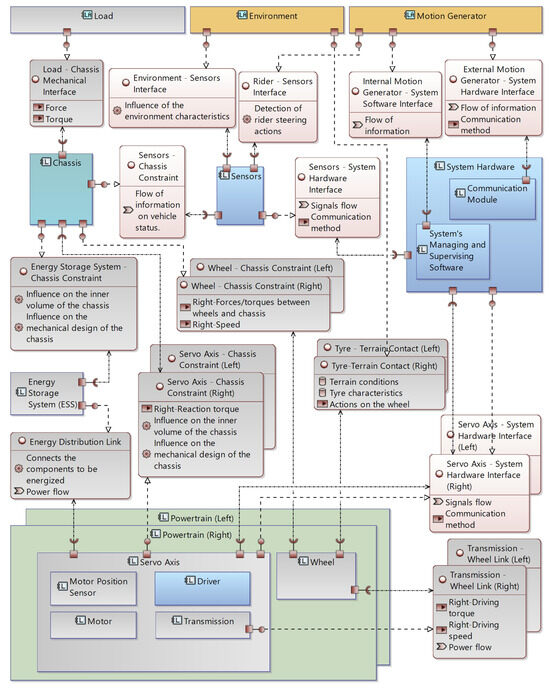
Figure 5.
Component interface diagram. The components and interfaces considered in steps 8–9 are represented in color, with the ones already defined but still relevant displayed in teal. The remaining ones are displayed in gray.
The design is structured in three sub-steps:
- 8a—Sensor Design: This sub-step involves the selection of sensors. In this phase, the choices related to the sensors concern, among others, the quantities to be measured, the accuracy, the input range, and the signal communication methods. Such choices are performed by the design team according to the analysis of the actors and the resulting design specifications.
- 8b—Control Hardware Design: This sub-step focuses on the selection and configuration of the control hardware, which must be capable of acquiring sensor data, executing control algorithms in real time, and interfacing with actuators and other components. Both computational performance and I/O capabilities are evaluated according to system needs.
- 8c—Control Software Design: This sub-step addresses the development of the control software. In the case of self-balancing vehicles, it includes the implementation of algorithms that ensure vehicle stability and respond to motion commands. More advanced control strategies may replace simpler regulators introduced in earlier design phases for the initial sizing of the actuation systems and of the mechanical elements; to this end the extensive body of research dedicated specifically to the control issue should be consulted to extract the maximal performances of the system. Depending on the sensor configuration and on the intended driving strategy, the control software may also include functionalities related to fault detection, motion planning, safety enhancement or user interface management.
2.5.13. Step 9
This step involves the analysis of the design output of step 8. Therefore, in this phase, the focus is not on the dynamic behavior of the vehicle but rather on the suitability of the sensors in terms of their input range and accuracy, and of their physical dimensions and placement on the vehicle. Another focus of this step is the validation of the compatibility between the dimensions of the control hardware and the vehicle’s geometry. The correctness and completeness of the software, and its compatibility with the chosen hardware, are also evaluated.
2.5.14. Design Check 4
This checkpoint enables the design team to judge the output of step 8, according to the analysis results from step 9. The design team must evaluate the vehicle sensors, hardware, control software, and geometry needed to install and use them. If the check is positive, the design process ends, and the final configuration is obtained. Otherwise, loop 4 permits the redesign of the vehicle geometry (or conversely of the sensors and of the control hardware) to satisfy the requirements highlighted in this phase.
2.5.15. V-Model Representation
The proposed design procedure might be alternatively represented, according to VDI Guideline 2206:2020 [41], as nested V-models, each one of them not representing a different maturity level but subsystems that are designed according to hierarchy levels, starting from the inner to the outer one. Figure 6 shows the V-model diagram of the proposed procedure, with color coding that matches that adopted for Figure 2. Conceptually, the flow chart and the V-model representations are equivalent; however, while the former is characterized by greater immediateness, the latter offers the benefits of standardization, higher emphasis on the testing and verification loops, and adoption within specialized industries (automotive, robotics and automation) that are of clear relevance for the development of systems such as the several variants of the CTWSBV. Compared to the diagram of Figure 1, the V-model and the flow chart representations do not offer an overview of the CTWSBV system itself, but rather of its design process.

Figure 6.
Nested V-model alternative description of the proposed design procedure.
More in detail, the inner V-model concerns the sizing of the powertrains and of the ESS, and the lateral action analysis; it includes steps 0 to 5, and loops 1 and 2. The considered interfaces and components are highlighted in Figure 3. The second V-model is related to the mechanical and aesthetic design and to the definition of the vehicle’s geometry, considering the components and interfaces highlighted in Figure 4; it represents the activities of steps 6 and 7 and includes the design check associated with loop 3. The outer V-model concerns steps 8 and 9, i.e., the definition of the sensors, the control hardware, and the control software, considering the components and interfaces shown in Figure 5. It includes a last design check and the associated loop 4; as explained in the description of the procedure, this loop does not bring back to the inner V-model (i.e., to step 0), but to the middle one, since at this stage, the possible design check failure should be corrected mainly through minor modifications of the vehicle’s geometry or through the redesign of the system’s control hardware and software architecture.
3. Results
In this section, each step of the procedure proposed by the authors and outlined in Section 2 is systematically applied to the design of a specific self-balancing vehicle. For this example, the vehicle should accommodate a single rider and be able to climb moderate slopes. The purpose of this case study is to concretely demonstrate the applicability of the proposed procedure, and to exemplify the kind of computations that may be performed to actually carry out its various steps. It should be noted however that the procedure itself neither overly constrains the choice of the adopted mathematical or numerical models, nor prescribes the level of sophistication of the techniques used in solving the several technical problems that arise during the design. For economy of exposition, therefore, each subproblem is treated as straightforwardly as possible. Alternative and more exhaustive analyses could have been adopted to perform the choices detailed below; however this does not invalidate the procedure itself, which is focused not on specific technical issues, but rather on the individuation of the minimal set of quantities that should be considered during the design, its logical sequencing, and its eventual organization over different teams with domain-specific skills.
3.1. Step 0
As explained in Section 2.5, at the beginning of the design procedure, the actors’ characteristics have to be defined; in this particular example, the considered actors interacting with the vehicle are as follows:
- Motion Generator: a single rider, responsible for the motion commands;
- Load: again constituted by the rider only;
- Environment: characterized by unpaved roads with a moderate maximum slope.
As a result of this set of actors, the main design specifications and conditions are as follows:
- The vehicle should be able to easily accommodate a rider of average height () and weight ();
- The maximum slope is ;
- The cruise speed is .
In reference conditions, the vehicle should possess a driving autonomy of around 2 , and, due to its intended use, the vehicle track w should be no greater than .
3.2. Step 1
Step 1 of the procedure concerns the first dynamic analysis of the system; Figure 7a depicts in particular a sketch of the lateral view of the vehicle, while Figure 7b reports an illustration of the corresponding longitudinal dynamic model.

Figure 7.
Lateral sketch of the vehicle and corresponding longitudinal dynamics model. (a) Lateral view of the system; (b) dynamics model in the longitudinal plane.
As already stated, the first design decision to be made is the one concerning the radius R of the wheel; due to the fact that the mass m and polar moment of inertia of this component are also relevant, it is possible already at this early stage to evaluate them. While the selection of the wheel is strongly related to the kind of terrain the vehicle is interacting with, it is also obviously constrained by the commercially available dimensions and types (that is, if a custom wheel design is not considered). Due to the specification of compatibility with unpaved roads, in this design example, a relatively large wheel is selected.
To enable the first computations, some estimates concerning the overall mass M, centroidal moment of inertia J, and center of gravity position of the loaded vehicle are also required; the numerical values chosen or estimated for all the needed quantities are reported in Table 2. At this early design step, a large degree of approximation is present in these estimates; it is therefore reasonable, though by no means mandatory, to initially avoid overly detailed dynamic models of the system, and to use instead more clearly interpretable simplified formulations.
Table 2.
Longitudinal dynamics parameters.
With reference in particular to the simple longitudinal model of Figure 7b, its equations of motion may be written in compact form as
In Equation (1), whose detailed treatment may be found in [35], is the sum of the torques acting on each wheel, while the angles and represent the pitch of the chassis and the rotation of the wheel; moreover,
In Equation (3) represents the rolling friction coefficient. As the dynamics of the vehicle in the longitudinal plane are intrinsically unstable, a stabilizing controller is also needed. Indeed, the controller is an integral and essential part of the CTWSBV; accordingly, as highlighted in Section 1, the control problem for this kind of system has been treated extensively in the current scientific literature. However, at this very early design step, the main goal is not the development of a highly optimized regulator, but rather a reasonable evaluation of the control torque and velocity requests at the wheel hubs. A straightforward regulator that guarantees the stability of the system can therefore be provisionally adopted, without the need to optimize its performances; these may become a key focus at later stages of the vehicle development. In this design example, a simple control system based on pole placement with full state feedback is used, as shown in Figure 8. The four poles of the controlled system were chosen as follows:

Figure 8.
Stabilizing control system based on pole placement with full state feedback.
The damping ratios and were both set to 0.7, and the two frequencies and obey the relationships and , where is the natural frequency of the open-loop system obtained by linearization of Equation (1) around .
Different simulations were performed considering not only the nominal loading conditions that correspond to the system configured according to the design parameters, but also cases in which the total mass of the vehicle (rider and chassis) is increased by and . In all these cases, the vehicle moves uphill, with a slope ; moreover, its motion is opposed by rolling friction (). The desired motion at the chassis selected for simulation purposes is reported in Figure 9; in particular, the linear position, velocity and acceleration profiles at the chassis are depicted in Figure 9a, Figure 9b and Figure 9c, respectively. Given the radius of the wheel and the vehicle velocity specifications, the angular velocity at the wheel hub may be easily determined.
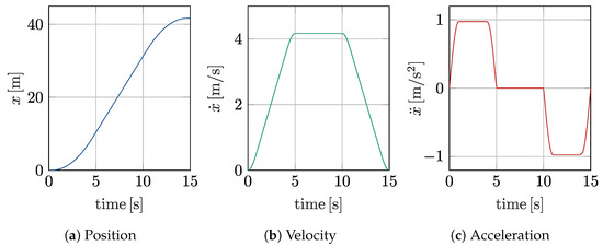
Figure 9.
Motion profile in terms of position, velocity and acceleration.
In each simulation, the gains of the control system were obtained according to the method detailed above. The resulting regulator achieves stability and a qualitatively acceptable velocity tracking error, as may be seen in Figure 10a,b.

Figure 10.
Time response of the CTWSBV longitudinal model controlled through pole placement.
The analysis of the total torque required at the wheels, whose results are reported in Figure 11a, has again been performed considering the different loading conditions described above. The required power at steady-state conditions has also been evaluated as a function of the slope for different loading conditions, considering an overall efficiency of 90%; the results are presented in Figure 11b.

Figure 11.
Torque requests at each wheel hub calculated at 100%, 125% and 150% of the total reference mass; the dashed lines represent the RMS values corresponding to the three considered conditions.
In the following steps, an estimate of the power required to run the vehicle is needed. Considering the steady-state speed and a flat ground, from the data presented in Figure 11b, it may be estimated that in the most challenging loading conditions, around is required to power the vehicle.
3.3. Step 2
This step of the procedure concerns the servo axis design given the velocity and torque requests obtained in step 1. A further design variable that should now be fixed is the rated voltage V of the motor; in this example, to ensure high electrical safety, a low value of is selected. Regardless of the specific figure, this first decision directs the designer towards more specific actuation technologies and the corresponding market segments.
As widely known, the motor and transmission unit should be selected jointly; while rather sophisticated procedures may be applied, a first sizing can be obtained according to the power required from the motor in steady-state conditions, at different slopes and for several possible reduction ratios i. Figure 12a shows the torque at the motor resulting from this preliminary analysis, while Figure 12b reports the required motor speeds. In both figures the selected motor’s nominal torque and speed are also indicated using black dashed lines.

Figure 12.
Steady-state requests placed on the motor at different reduction ratios; horizontal dashed lines indicate the rated torque and velocity. (a) Required motor torque at different reduction ratios and slopes. (b) Required motor speed at different reduction ratios.
In particular, the actuator chosen in this specific example is the DC motor series 75PX type B14 PAM80 from Siboni s.r.l., Forlì, Italy, coupled with a planetary gearbox model PEII090-010 from Apex Dynamics inc., Taichung City, Taiwan R.O.C., characterized by a reduction ratio . The characteristics of the motor and transmission are summarized in Table 3.
Table 3.
Main properties of the selected motors and transmissions.
As is clear from Figure 12a,b, there are significant margins mainly in terms of torque, but also of velocity. As a matter of fact, the motor torque for a slope is about the nominal one. The reason for this choice is that such a motor allows the vehicle to work also in more demanding off-design conditions arising, e.g., as a consequence of the rider’s weight or steeper slopes. The choice of the motor and the transmission is then confirmed using the data concerning the transient dynamic analysis of the system. In particular, the RMS required torque with is , while the peak one is ; this translates into RMS and peak currents of 31 and 63 , which are easily handled by the motor. Knowing the motor’s supply voltage, its type, and the required current, the power stage of the driver can be defined; besides the supply voltage, it must guarantee the current to the motor, in terms of both peak and nominal values. Together with the motor and the driver, the associated sensors may also be selected, keeping in mind that the position measurements also have systemic significance; therefore, the logic stage of the driver must include a communication channel suitable for the propagation of the angular position information to the system hardware. In this particular example, each motor is associated with a 2048 ppr encoder, the Eltra EL 48C. At the end of this stage, the transmissions and the motors are fully designed; moreover, the specifications needed to correctly size the power stage of the drivers have been determined; a general specification for the logic stage has also been formulated.
3.4. Step 3 and Design Check 1
The knowledge of the rated voltage, the absorbed currents and the required power allows—together with the driving autonomy specification—the proper sizing of the main element of the energy storage system, namely the battery pack. Considering the desired two-hour ride on flat ground, in step 1, it was determined that this running condition requires a power of approximately 130 ; consequently a total of four V – Ah lead accumulators have been chosen, in order to guarantee the required driving autonomy while avoiding deep discharge damage. The accumulators are wired in series two by two, and the resulting pairs are then connected in parallel; in this way the energy storage system is able to provide the 24 needed by the motor.
A more detailed evaluation of the power and energy requests has also been performed considering the duty cycle represented in Figure 13. The vehicle, at 150% of its nominal load, operates on flat ground in steady-state conditions for approximately 70% of the cycle, while the remaining time is spent accelerating and decelerating. The resulting power and energy requirements are calculated considering a total efficiency of the mechanical, actuation and energy storage systems of 90%.

Figure 13.
Duty cycle used to evaluate ESS requirements.
In these conditions, the choice based on steady-state considerations still appears appropriate; in particular, during the transient conditions, the peak torque reaches 40 ; this corresponds to a current peak of 40 , which is entirely compatible with the selected accumulators.
At the end of this step, the choices concerning the electrical characteristics of the motors and of the ESS are validated as required by design check 1. For final validation, an exhaustive, specialized analysis that takes into account effects such as voltage sag, heat generation, cell unbalances, battery life, and constraints on regenerative braking should be requested.
3.5. Step 4
This step is related to the analysis of the lateral actions with main reference to the possibility of overturning. The lateral analysis of the vehicle, in addition to the parameters listed in Table 2, requires the assumption of a possible range for the track dimension. The range is chosen remembering that the vehicle is designed for a single rider, without the presence of any load, and that compactness should be one of its characteristics as much as possible; hence, the chosen range is mm. The analysis results in a clear outline of the relation between the parameters which influence the vehicle’s overturning.
To this end, with reference to the transverse plane view of the vehicle sketched in Figure 14a and the corresponding model of Figure 14b, simple dynamic equilibrium equations can be written to find a relationship between the speed, the trajectory’s curvature radius and the vehicle’s track. Considering a curve of radius negotiated at a constant tangential speed v, two forces are acting on the vehicle’s center of mass: the vertical force due to the gravity, and the lateral centrifugal force due to centripetal acceleration; the normal and lateral reactions , , and at the wheels balance and . In the limiting case of incipient rollover, a wheel will be completely unloaded; considering in this situation the rotational equilibrium around the wheel–terrain contact point at the loaded wheel, the following inequality may be written:
where is the lower-bound limit of the curvature radius, l is the distance of the center of mass from the wheels’ axis, R is the wheels’ radius, w is the vehicle’s track and g is the gravity acceleration.
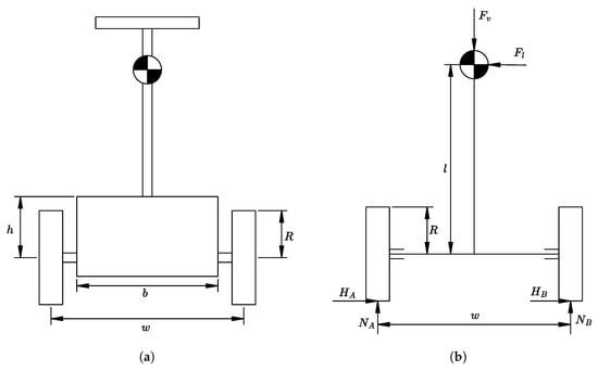
Figure 14.
Front sketch of the vehicle and corresponding lateral dynamics model. (a) Front view of the system. (b) Dynamics model in the transverse plane.
Inequality (7) is graphically represented in Figure 15, where each straight line corresponds to a specific curve radius; the area under each line includes all the possible working conditions of the vehicle, in terms of track and speed limit, for the corresponding curvature. Such information is very important for evaluating the influence of the geometric configuration on the vehicle’s transverse behavior, and also for the vehicle’s safety management. The track should be chosen in order to strike a balance between the vehicle’s dimension and maneuverability; in this case, a value of 670 has been chosen. According to this choice and given a vehicle speed, Figure 15 provides the minimum possible curvature radius of a turn that can be successfully negotiated without rollover.
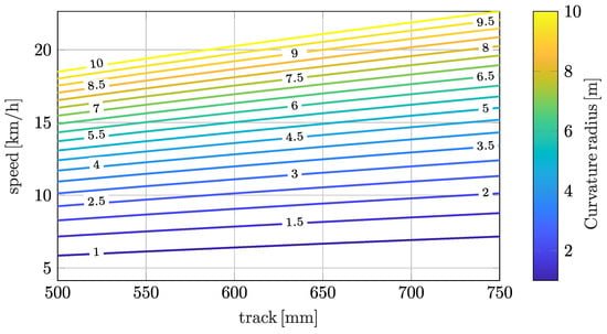
Figure 15.
Curvature radius lower-bound limit as function of vehicle track and speed.
The analysis of the above-described limiting case also allows us to highlight the maximum non-motive forces and torques that should be withstood by the wheel axle and ultimately by the chassis.
3.6. Step 5 and Design Check 2
At this step of the procedure, the main components have been chosen and so their inertial characteristics are known. Hence, with the updated parameters, longitudinal and transverse dynamic analyses are repeated.
The updated results have been used in the proposed example to confirm the preliminary design, as required in checkpoint 2 shown in Figure 2.
3.7. Step 6
The second design check has been passed and now the detailed configuration of the system is to be defined. Such detailed design should consider that the chassis must contain the chosen components and that the required mechanical strength needs to be guaranteed. Furthermore, part of the design team should take care of the aesthetic concerns that affect the geometry. The mechanical configuration chosen for the system is shown in Figure 16a,b.

Figure 16.
Internal layout of the chassis and 3D view of the system. (a) Chassis internal layout; (b) 3D view of the system.
In particular, Figure 16a represents the solid model of the vehicle, while Figure 16b depicts an inner schematic view that shows the internal layout of the chassis, which houses the motors (a), the gearboxes (b), the timing belt transmissions and the accumulators. Timing belts have been introduced in the detailed configuration to reduce the bulk of the vehicle, as this solution results in a good compromise between chassis dimensions, the vehicle’s track and placement of the components. For the same reasons, the position of the support base has been chosen above the wheels’ axles.
Table 4 reports the main vehicle’s dimensions; the symbols can easily be found in Figure 7a and Figure 14a.
Table 4.
Main chassis dimensions arising from the detailed design.
Concerning the mechanical strength of the vehicle, at this design stage, it is possible to verify it in a variety of working conditions, considering the detailed mechanical design developed so far and the loads that are obtained by the preceding dynamic analysis of the system. As an example, Figure 17 shows the results of the stress distribution within the chassis obtained using a commercial Finite Element Analysis software tool (Hexagon MSC Nastran 2024.1). This specific assessment, which evaluates the quasi-static conditions that occur during steady-state longitudinal motion, is constructed as follows: the considered material is an aluminum alloy; the wheel axle bearings are assumed to be fixed; and finally the applied forces replicate those that occur due to the weight of the payload. Other Finite Element Analyses representative of other operating conditions are not reported for the sake of conciseness.

Figure 17.
Stress analysis of the chassis.
3.8. Step 7 and Design Check 3
In this step, according to the detailed configuration previously defined, another dynamic analysis is made considering both the longitudinal and the transverse behavior of the vehicle. More advanced dynamic models or multibody simulation tools may be used for this step, as near-complete and very detailed information concerning the mechanical design is now available thanks to the preceding step 6.
The results of this further analysis are evaluated at the third checkpoint; in this example the results of the dynamic analysis of step 7 satisfy the design target; the detailed design is therefore confirmed.
3.9. Step 8
As already discussed, in general terms, the design of the system hardware is conditioned not only by the type and number of the adopted sensors, but also by the properties of the motor drivers. In this case study, the drivers assume the typical configuration prevalent in the automotive sector, as they possess both power and logic stages. Having their own dedicated processor, they are able to operate at a high frequency in order to acquire the rotor position measurements and to close the current loops, while also supporting a CAN interface towards the system hardware. While not focusing on the driver’s internal components and connections, Figure 18 highlights the main interfaces of the driver, which implement those described at a general and more abstract level in Figure 1.

Figure 18.
Custom DC driver developed for the application.
Concerning on the other hand the selection of sensors, all CTWSBV variants require at least a tilt measurement in order to stabilize the vehicle; in the specific case of a self-balancing vehicle for personal mobility, the system must incorporate an additional sensor to detect the rider’s intention to initiate a turn (steering intention sensor). Given these considerations, the overall system architecture adopted for the system is reported in Figure 19.

Figure 19.
Control architecture designed for the proposed case study.
- 8a—Sensor Design: This step focuses on the selection and integration of the sensing devices. The measurement of the vehicle’s attitude and angular velocity is achieved using a triaxial gyroscope and a triaxial accelerometer, both integrated in the MPU-6050 MEMS inertial platform, which exposes an I2C interface. To detect the driver’s intention to steer, the handlebar of the vehicle is instrumented with strain gauges that measure deformation caused by applied forces. The selected transducer is the HBM 1-LY13-6/120 strain gauge. The sensors defined here are in addition to those that belong to the power drive systems. Since the output signal is low in amplitude, it is first amplified and then acquired by an analog-to-digital converter possessing an I2C interface.
- 8b—Control Hardware Design: The system hardware is based on a Raspberry Pi platform, which natively includes the I2C interface needed to acquire the measurements provided by the inertial unit and by the amplification and acquisition hardware associated with the strain gauges; the Raspberry Pi has been furthermore equipped with a CAN add-on board to communicate with the drivers. The work group tackling control hardware design will evaluate in detail fundamental aspects such as bus latency and utilization. A preliminary evaluation may be performed considering a single bus working at a Baud rate of 1 and used to control the two drivers. A standard CAN frame with a payload of 64 bit (used to encode either the setpoint or the feedback signals) is composed of 111 bit. Considering two frames for the setpoints and two frames for the feedback, the total transmission time is 444 , which is compatible with a control loop operating at 500 . Taking as a reference the pole placement controller configured according to step 1 of the design example and the masses defined so far, the frequencies of the closed-loop system are and , i.e., at least two orders of magnitude lower than the hypothesized 500 control frequency.
- 8c—Control Software Design: As each driver is capable of closing the local current control loop, the Raspberry Pi handles the execution of the higher-level control loops and the system logic. The Raspberry Pi acquires all the sensor data and implements the control algorithms to ensure the dynamic stability of the vehicle. Based on the attitude measurements and the steering intention estimated from the strain gauges, the central unit computes the desired current setpoints and transmits them via CAN to the respective drivers. The team working on software development will need to take into account the requirements and technical issues associated with latencies and real-time constraints.
3.10. Step 9 and Design Check 4
In this step, a further analysis of the system is made, but differently from the previous steps, it does not concern the dynamic behavior of the vehicle. The analysis is focused on the suitability of the sensors with respect to the necessary measurements, and to their ability to be physically placed on the vehicle. The feasibility of the control hardware placement is also evaluated. Such verifications are the subject of the last checkpoint; any possible problem that could lead to a non-verification does not affect the choices made up to step 5, but just the mechanical design, mainly concerning the geometric configuration of the vehicle. As a matter of fact, if the design check is not fulfilled, loop 4 of the design procedure’s flow chart brings us back to step 6 where the geometry is modified considering the dimensions of the sensors and the control hardware.
Once checkpoint 4 is successfully passed, the design is completed.
3.11. Validation of the Designed Virtual Prototype
The validation of the designed prototype is downstream of the design procedure itself. In this example the validation is performed on a virtual prototype developed using MSC Adams (Hexagon Adams 2024.1) and Matlab/Simulink (R2024a); the two computing environments allow sophisticated co-simulations of the CTWSBV. ADAMS facilitates the development of a very detailed mechanical model, inclusive of the tire–terrain contacts and of the interactions between the chassis and the rider; on the other hand, Matlab/Simulink allows us to implement a large portion of the control software, and also to simulate non-idealities introduced by sampling, quantization, and measurement noise.
Interestingly, the two solvers are coupled to each other through interfaces that conceptually match some of those presented in Figure 1. In particular the relevant ones are the servo axis–system hardware interface that connects the control hardware to the logic stage of the driver, and the sensor–system hardware interface.
Figure 20a shows the developed ADAMS model, while the diagram of Figure 20b represents its Simulink blocks to be used within the co-simulation. It can be seen that the multibody model allows the simulation of the full vehicle’s nonlinear dynamics, in all directions of motion. A diagram that illustrates the approach realized by the interaction between ADAMS and Matlab/Simulink is shown in Figure 21, while Figure 22 depicts the relevant results of a simulation, compared to those obtained with the longitudinal analytical model, where the vehicle reaches a steady-state velocity, starting from a rest condition.

Figure 20.
MSC ADAMS model and Simulink blocks. (a) MSC ADAMS model; (b) Simulink blocks of Adams model.

Figure 21.
MSC ADAMS–Matlab/Simulink co-simulation diagram.

Figure 22.
Comparison between multibody and analytical models.
4. Discussion
While the proposed procedure has been applied in Section 3 on a specific vehicle configuration, it could be equally applied to other variants owing to its high level of generality; indeed, the procedure is not tailored to a particular configuration, and may be used to design any kind of self-balancing vehicle; moreover, the selection of simulation and analysis tools is far from being rigidly constrained by the proposed method. The analysis of the mechanical dynamics of a vehicle is one of the cores of the proposed procedure, as it constitutes the foundation for most of the design and validation steps, starting from step 1 and then repeatedly applied in the following ones; at the same time, there is also considerable freedom in the selection of the adopted model; indeed, the above description of the proposed procedure suggests that simple longitudinal and lateral models are enough to properly design the vehicle. However, the same goal could be achieved using different or more complex models, whose adoption depends on the choice made by the design team and on the available modeling tools. For example, a single analytical model that also accounts for the coupling between lateral and longitudinal motions could substitute the ones exemplified here. Another option is the use of multibody software, not just as a final validation of a virtual prototype as exemplified above, but during the design. A multibody model allows us to introduce the actors with a higher degree of detail; for example, the environment can be modeled with more accuracy, simulating the terrain shape and the interaction between the ground and tire, according to the different characteristics of both.
Also the load and the rider can be accurately modeled inside the multibody simulation environment, while an external motion generator may be included in the overall model by means of a co-simulation approach, together with a prototype of the control and managing software. As a general suggestion, simpler models should be preferred during the early stages and iterations of the engineering process, as they allow us to clearly highlight the most important features of the system; as the design becomes increasingly refined, more sophisticated computational models may prove valuable especially for validation purposes, as they allow realistic simulations of the vehicle. It should however be noted that, despite the ample freedom in the choice of the modeling approach, the minimal set of input–output quantities specified by the procedure for each step has a general validity, and is required for the rational design of the vehicle. A further benefit of this clear subdivision in steps is the possibility of distributing the design responsibilities over several working groups, each possessing specific domain expertise; these groups can be provided with a well-defined set of inputs on the one hand, and tasked with the determination of specific outputs on the other.
Concerning on the other hand the suitability of the procedure for the design of different vehicle variants, this is allowed by the three actors proposed by the authors, whose specific characterization identifies the design specifications and conditions. The components of the different variants naturally emerge correctly sized from the same design steps, which remain unchanged. To exemplify the adaptability of the proposed methods to different CTWSBV classes, focus may be placed on three particular types of vehicle whose differences concern not only the performances in terms of transportable load, maximum speed, maximum acceleration and type of traversable terrain, but also the intended application:
- “Sport” configuration. The vehicle, steered by a single rider, has high performance that allows it to reach high speed and accelerations, and to move on uneven terrain and along steep slopes.
- “Twin” configuration. The vehicle can accommodate not only the rider, but also a passenger. It is supposed to move on paved roads with modest slopes, and with speed and acceleration values typically suited to personal transportation in an urban environment.
- “Autonomous” configuration. The vehicle is used for the transportation of passive loads, and the motion commands are received from an external automated drive system. It is able to transport higher loads with respect to the previous configurations, moving however on flat terrain at limited speed and acceleration, as appropriate, e.g., in a warehouse.
The proposed procedure allows the design of any of the three configurations, as it easily accounts for the specificities of each variant that have very different application fields that result, among other things, in significantly different masses, inertias and motion requirements.
As a result of the different characteristics of the actors, each component assumes a specific physical configuration, which results however from the same design steps already illustrated. A typical example is the powertrain unit; for the “Sport” variant, the motors’ torque and speed need to be higher than the ones required for the other two configurations. Moreover, due to the motion on unpaved terrain, also the wheels, both in terms of dimension and selected tire, may be different with respect to the other cases. Different required power and energy also lead to a different sizing of the energy storage system; the size and type of battery will therefore differ according to the required currents, voltages and capacities. Concerning the physical configuration of the system hardware block and of the included system software and communication module, the number of devices on which they could be physically distributed depends on the choice made by the design team, also according to the desired vehicle performances and application requirements. It is clear for example that vehicles for personal transportation do not strictly require a communication module, which may however still be useful for ancillary functions, especially in a context of advanced smart mobility; on the other hand, such a component is mandatory in the autonomous configuration to receive external instructions in order to, e.g., coordinate with an entire fleet of similar AGVs. Also, the sensor block could have a different physical configuration depending on the specific type of vehicle. The differences could concern the position of the sensors, their characteristics, their number, and their type, with more advanced and sophisticated ones more likely appearing in the autonomous version. Finally, it may be remarked that the chassis’s physical configuration can change too in terms of geometry and material, depending on the dimension and mass of the transported load, the interaction with the environment, the housed components, and in general the performance required from the vehicle.
Similarly to what happens to the components, the high-level interfaces are the same for each different type of vehicle, while their physical implementation is adapted to the configuration of the relevant connected component, which in turn is affected by the variant’s specificities. For example, the interfaces between the system’s managing–supervising software and sensors, motion generator, and drivers are signal flows (commands, measurements, etc.), but the type of communication could be different according to the specific physical implementation, happening, e.g., simply through analogue signals, or according to a suitably selected communication protocol. Considering in particular the driver–system hardware interface, competing design solutions are representable with the proposed methodology; in the case study proposed in the previous section, a modular architecture typical of automotive systems was adopted: the drivers possess both a power and a logic stage and are thus in large part decoupled from the system hardware, with which they communicate over the CAN bus; the system hardware assumes in this case mainly a supervisory role, while the drivers operate at higher frequencies in order to perform measurements and close the current control loops. Different architectures could however be conceived, for example a monolithic one in which the system hardware directly interfaces with the drivers’ power stages and with the rotor position sensors.
5. Conclusions
This work proposes a general procedure for the design of different classes of coaxial two-wheeled self-balancing vehicles. The procedure avails itself of a modeling language typical of Model-Based Systems Engineering to formally express the proposed representation of the vehicle.
The procedure effectively treats the vehicles as mechatronic systems characterized by interacting components that span mechanical, electrical, electronic and algorithmic subdomains, and exchange physical and logical flows between each other through suitable interfaces. The design procedure covers all stages of the engineering process, starting from the analysis of the requirements and gradually leading to the full design of the system. Along its steps, a minimal set of quantities (design specifications, reference operating conditions, design variables and resulting data) are singled out as especially relevant for the proportionate sizing and logical co-design of the several elements constituting the vehicle; this specific contribution of the present work also allows the design workload to be split over several working groups, each provided with the necessary inputs and tasked with clearly defined responsibilities. The systematic application of the proposed method on an actual case study demonstrates the practical value and actual applicability of the procedure; as the latter rests on a very general conceptualization and description of the vehicle, it remains equally applicable to different variants and classes of this overall type of system.
The procedure allows the design of vehicles characterized by more complex management strategies, such as those aiming at safety enhancement. This type of management strategy impacts only the sensor components and the system’s managing and supervising software. For example, the vehicle can be equipped with force sensors to detect the actions exchanged between the rider and the vehicle. Such measurements could be associated with panic or emergency reactions, and managed by the control software.
Future research activities on this topic concern the validation of the dynamic models proposed for the procedure by means of experimental tests on the full realization of the designed vehicle.
Author Contributions
Conceptualization, P.R. and R.S.; methodology, P.R. and R.S.; software, P.R., R.S. and J.S.; validation, R.S., F.C. and J.S.; investigation, P.R., R.S., F.C. and J.S.; writing—original draft preparation, R.S., F.C. and J.S.; supervision, P.R. All authors have read and agreed to the published version of the manuscript.
Funding
The research was funded by the University of Bergamo. Fund code: 60RIGH20.
Institutional Review Board Statement
Not applicable.
Informed Consent Statement
Not applicable.
Data Availability Statement
The original contributions presented in this study are included in the article. Further inquiries can be directed to the corresponding author.
Conflicts of Interest
The authors declare no conflicts of interest.
References
- Huang, J.; Ding, F.; Fukuda, T.; Matsuno, T. Modeling and velocity control for a novel narrow vehicle based on mobile wheeled inverted pendulum. IEEE Trans. Control Syst. Technol. 2013, 21, 1607–1617. [Google Scholar] [CrossRef]
- Larimi, S.; Zarafshan, P.; Moosavian, S. A new stabilization algorithm for a two-wheeled mobile robot aided by reaction wheel. J. Dyn. Syst. Meas. Control. Trans. ASME 2015, 137, 011009. [Google Scholar] [CrossRef]
- D’Arrigo, A. Veicolo Elettrico Sperimentale a Due Ruote Parallele Coassiali Indipendenti. Master’s Thesis, EPFL/Politecnico di Milano, Lausanne, Switzerland; Milan, Italy, 1997. [Google Scholar]
- Grasser, F.; D’Arrigo, A.; Colombi, S.; Rufer, A. JOE: A mobile, inverted pendulum. IEEE Trans. Ind. Electron. 2002, 49, 107–114. [Google Scholar] [CrossRef]
- Mohamed Gad, O.; Saleh, S.; Bulbul, M.; Khadraoui, S. Design and Control of Two Wheeled Self Balancing Robot (TWSBR). In Proceedings of the 2022 Advances in Science and Engineering Technology International Conferences, ASET 2022, Dubai, United Arab Emirates, 21–24 February 2022. [Google Scholar] [CrossRef]
- Navinkumar, T.; Amala Praveen, A.; Sasirekha, P.; Gokila, P.; Kalaivani, C.; Prabhu, V. Design of DC-DC Converter based Self Balancing Segway Transporter for Indoor Applications. In Proceedings of the 6th International Conference on Computing Methodologies and Communication, ICCMC 2022, Erode, India, 29–31 March 2022; pp. 23–26. [Google Scholar] [CrossRef]
- Patel, C.; Putta, N.; Sri Manikanta, A.; Reddy, E.; Babu, K. Design, Analysis and Development of Virtual Working Model of Self Balancing Robot. In Lecture Notes in Mechanical Engineering; Springer Nature: Singapore, 2023; pp. 339–350. [Google Scholar] [CrossRef]
- Velagic, J.; Kovac, I.; Panjevic, A.; Osmanovic, A. Design and Control of Two-Wheeled and Self-Balancing Mobile Robot. In Proceedings of the Elmar—International Symposium Electronics in Marine, Zadar, Croatia, 13–15 September 2021; pp. 77–82. [Google Scholar] [CrossRef]
- Putov, A.; Ilatovskaya, E.; Kopichev, M. Self-balancing Robot Autonomous Control System. In Proceedings of the 2021 10th Mediterranean Conference on Embedded Computing, MECO 2021, Budva, Montenegro, 7–10 June 2021. [Google Scholar] [CrossRef]
- Shekhawat, A.; Rohilla, Y. Design and Control of Two-wheeled Self-Balancing Robot using Arduino. In Proceedings of the International Conference on Smart Electronics and Communication, ICOSEC 2020, Trichy, India, 10–12 September 2020; pp. 1025–1030. [Google Scholar] [CrossRef]
- Chien, S.Y.; Wang, A.S.; Wong, C.C. Design and Implementation of Two-Wheeled Self-Balancing Vehicle Based on Load Sensors. In Proceedings of the 2020 International Conference on System Science and Engineering, ICSSE 2020, Kagawa, Japan, 31 August–3 September 2020. [Google Scholar] [CrossRef]
- Komor, D.; Roman, R.C.; Precup, R.E.; David, R.C.; Pamfilii, I. Models of Two-Wheeled Mobile Robots with Experimental Validation. In Proceedings of the SACI 2020–IEEE 14th International Symposium on Applied Computational Intelligence and Informatics, Timisoara, Romania, 21–23 May 2020; pp. 211–216. [Google Scholar] [CrossRef]
- Pawananont, K.; Charoensuk, K. Design of a Two-Wheeled Auto-Balancing Robot under Impulse Interruption. ECTI Trans. Electr. Eng. Electron. Commun. 2022, 20, 438–449. [Google Scholar] [CrossRef]
- Nghia, V.; Van Thien, T.; Son, N.; Long, M. Adaptive neural sliding mode control for two wheel self balancing robot. Int. J. Dyn. Control 2022, 10, 771–784. [Google Scholar] [CrossRef]
- Olmez, Y.; Koca, G.; Akpolat, Z. Clonal selection algorithm based control for two-wheeled self-balancing mobile robot. Simul. Model. Pract. Theory 2022, 118, 102552. [Google Scholar] [CrossRef]
- Akhavan, M.; Parvahan, H.; Manzar, M. Design and Implementation of a Data-Driven Controller for a Two-Wheeled Self-Balancing Robot. In Proceedings of the 2022 30th International Conference on Electrical Engineering, ICEE 2022, Tehran, Iran, 17–19 May 2022; pp. 55–59. [Google Scholar] [CrossRef]
- Fikri, M.; Djamari, D.; Levy, S. H-Infinity Controller Design of Two-Wheeled Mobile Robot under Disturbance. In Proceedings of the 2021 International Seminar on Intelligent Technology and Its Application: Intelligent Systems for the New Normal Era, ISITIA 2021, Virtual, 21–22 July 2021; pp. 147–152. [Google Scholar] [CrossRef]
- Razmjooy, N.; Ramezani, M. Robust optimal control of two-wheeled self-balancing robot using Chebyshev inclusion method. Majlesi J. Electr. Eng. 2018, 12, 13–21. [Google Scholar]
- Martins, R.; Nunes, F. Control system for a self-balancing robot. In Proceedings of the 2017 4th Experiment at International Conference: Online Experimentation, exp. at 2017, Faro, Portugal, 6–8 June 2017; pp. 297–302. [Google Scholar] [CrossRef]
- Yuan, S.; Lei, G.; Bin, X. Dynamic modeling and sliding mode controller design of a two-wheeled self-balancing robot. In Proceedings of the 2016 IEEE International Conference on Mechatronics and Automation, IEEE ICMA 2016, Harbin, China, 7–10 August 2016; pp. 2437–2442. [Google Scholar] [CrossRef]
- Huang, Y.; Chen, H.; Qin, L. Design of self-balancing vehicle based on cascade PID control system. In Proceedings of the 2022 4th International Conference on Advances in Computer Technology, Information Science and Communications (CTISC), Suzhou, China, 22–24 April 2022; pp. 1–4. [Google Scholar]
- Ramadhan, B.; Binugroho, E.H.; Dewanto, R.S.; Pramadihanto, D. PENS-wheel (self balancing one-wheel vehicle) mechanical design and sensor system. In Proceedings of the 2016 International Electronics Symposium (IES), Denpasar, Indonesia, 29–30 September 2016; pp. 438–443. [Google Scholar]
- Monesh, M.S.; Kumar, A.H.; Durairaj, R. Comprehensive Review of Design and Development of a Self-Balancing Robot with Stability Control for Uneven Surfaces. Int. J. Mech. Eng. Technol. (IJMET) 2025, 16, 140–172. [Google Scholar] [CrossRef]
- Walden, D.D.; Shortell, T.M.; Roedler, G.J.; Delicado, B.A.; Mornas, O.; Yip, Y.S.; Endler, D.; International Council on Systems Engineering (INCOSE) (Eds.) Systems Engineering Handbook: A Guide for System Life Cycle Processes and Activities, 5th ed.; Wiley: Hoboken, NJ, USA, 2023. [Google Scholar]
- Stetter, R. Methodical and model-based design of automated vehicles. Stud. Syst. Decis. Control 2020, 201, 59–91. [Google Scholar] [CrossRef]
- Zheng, C.; Hehenberger, P.; Le Duigou, J.; Bricogne, M.; Eynard, B. Multidisciplinary design methodology for mechatronic systems based on interface model. Res. Eng. Des. 2017, 28, 333–356. [Google Scholar] [CrossRef]
- Hirz, M. An approach supporting integrated modeling and design of complex mechatronics products by the example of automotive applications. In Proceedings of the WMSCI 2018—22nd World Multi-Conference on Systemics, Cybernetics and Informatics, Orlando, FL, USA, 8–11 July 2018; Volume 3, pp. 161–166. [Google Scholar]
- Zheng, C.; Qin, X.; Eynard, B.; Li, J.; Bai, J.; Zhang, Y.; Gomes, S. Interface model-based configuration design of mechatronic systems for industrial manufacturing applications. Robot. Comput.-Integr. Manuf. 2019, 59, 373–384. [Google Scholar] [CrossRef]
- Khandoker, A.; Sint, S.; Gessl, G.; Zeman, K.; Jungreitmayr, F.; Wahl, H.; Wenigwieser, A.; Kretschmer, R. Towards a logical framework for ideal MBSE tool selection based on discipline specific requirements. J. Syst. Softw. 2022, 189, 111306. [Google Scholar] [CrossRef]
- Schmidt, M.M.; Stark, R. Model-Based Systems Engineering (MBSE) as computer-supported approach for cooperative systems development. In Proceedings of the ECSCW, Siegen, Germany, 13–17 June 2020. [Google Scholar] [CrossRef]
- Bajzek, M.; Fritz, J.; Hick, H.; Maletz, M.; Faustmann, C.; Stieglbauer, G. Model Based Systems Engineering Concepts. In Systems Engineering for Automotive Powertrain Development; Hick, H., Küpper, K., Sorger, H., Eds.; Springer International Publishing: Cham, Switzerland, 2020; pp. 1–40. [Google Scholar] [CrossRef]
- Caliò, E.; Di Giorgio, F.; Pasquinelli, M. Deploying Model-Based Systems Engineering in Thales Alenia Space Italia. In Proceedings of the CIISE, Turin, Italy, 14–16 November 2016; pp. 112–118. [Google Scholar]
- Badache, N.; Roques, P. Capella to SysML Bridge: A Tooled-up Methodology for MBSE Interoperability. In Proceedings of the 9th European Congress on Embedded Real Time Software and Systems (ERTS 2018), Toulouse, France, 31 January–2 February 2018. [Google Scholar]
- Roques, P. MBSE with the ARCADIA Method and the Capella Tool. In Proceedings of the 8th European Congress on Embedded Real Time Software and Systems (ERTS 2016), Toulouse, France, 27–29 January 2016. [Google Scholar]
- Righettini, P.; Strada, R.; Santinelli, J. Design of a self balancing vehicle as a test rig for safety control strategies investigations. In Proceedings of the ASME Design Engineering Technical Conference, Virtual, 17–19 August 2021; Volume 7. [Google Scholar] [CrossRef]
- Righettini, P.; Strada, R.; Cortinovis, F. Experimental Evaluation of Centralized Control Strategies on a 5R Robot. Mech. Mach. Sci. 2024, 163, 334–342. [Google Scholar] [CrossRef]
- Righettini, P.; Legnani, G.; Cortinovis, F.; Tabaldi, F.; Santinelli, J. Real Time MEMS-Based Joint Friction Identification for Enhanced Dynamic Performance in Robotic Applications. Robotics 2025, 14, 36. [Google Scholar] [CrossRef]
- Zhou, L.; Gao, J.; Li, Q.; Hu, C. Simulation study on tractive performance of off-road tire based on discrete element method. Math. Biosci. Eng. 2020, 17, 3869–3893. [Google Scholar] [CrossRef] [PubMed]
- Bekakos, C.A.; Papazafeiropoulos, G.; O’Boy, D.; Prins, J.; Mavros, G. Off-road tire-terrain interaction: An analytical solution. SAE Int. J. Commer. Veh. 2016, 10, 244–251. [Google Scholar] [CrossRef]
- Righettini, P.; Strada, R.; Cortinovis, F. General Procedure for Servo-Axis Design in Multi-Degree-of-Freedom Machinery Subject to Mixed Loads. Machines 2022, 10, 454. [Google Scholar] [CrossRef]
- Graessler, I.; Hentze, J. The new V-Model of VDI 2206 and its validation das Neue V-Modell der VDI 2206 und seine Validierung. At-Autom. 2020, 68, 312–324. [Google Scholar] [CrossRef]


Disclaimer/Publisher’s Note: The statements, opinions and data contained in all publications are solely those of the individual author(s) and contributor(s) and not of MDPI and/or the editor(s). MDPI and/or the editor(s) disclaim responsibility for any injury to people or property resulting from any ideas, methods, instructions or products referred to in the content. |
© 2025 by the authors. Licensee MDPI, Basel, Switzerland. This article is an open access article distributed under the terms and conditions of the Creative Commons Attribution (CC BY) license (https://creativecommons.org/licenses/by/4.0/).