Abstract
Addressing the insufficient research on the aerodynamic performance of the coupled last stage and exhaust hood structure in compact marine steam turbines under off-design conditions, this paper establishes for the first time a fully three-dimensional coupled model. It systematically analyzes the influence of the last-stage moving blade shrouds and exhaust hood stiffeners on steam flow loss, static pressure recovery, and vibrational excitation. The research methodology includes the following: employing a hybrid structured-unstructured meshing technique, conducting numerical simulations based on the Shear Stress Transport (SST) turbulence model, and utilizing the static pressure recovery coefficient, total pressure loss coefficient, and cross-sectional flow velocity non-uniformity as performance evaluation metrics. The principal findings are as follows: (1) After installing self-locking shrouds on the moving blades, steam flow loss is reduced by 4.7%, and the outlet pressure non-uniformity decreases by 12.3%. (2) Although the addition of cruciform stiffeners in the diffuser section of the exhaust hood enhances structural rigidity, it results in an 8.4% decrease in the static pressure recovery coefficient, necessitating further optimization of geometric parameters. (3) The coupled model exhibits optimal aerodynamic performance at a 50% design flow rate and 100% design exhaust pressure. The results provide a theoretical basis for the structural optimization of low-noise compact steam turbines.
1. Introduction
Compact marine steam turbines are a highly efficient power device. These are extensively utilized in nuclear-powered icebreakers, ocean platforms, aircraft carriers, and submarines. The exhaust hood, a critical component of the steam turbine system, serves two primary functions: first, it guides the steam to change its flow direction, where the steam, after turning by 90° from the last stage, enters a condenser through the exhaust hood; second, it decelerates and expands the steam, converting its residual kinetic energy into pressure energy. Ships at sea encounter complex situations, and the turbine unit is required to handle various challenging conditions. Thus, the exhaust hood must exhibit excellent aerodynamic performance to ensure stable operation of the turbine system. Moreover, structural design is a key factor in optimizing the performance of the exhaust hood. Effective structural design can provide a stable exhaust environment, reducing pressure fluctuation and energy loss, thereby enhancing the efficiency of the unit. The design must also consider the compactness and lightweight nature of the exhaust hood to improve the ship’s payload capacity and operational efficiency. Testing and optimizing the aerodynamic performance and structural design of the exhaust hood can enhance steam expansion efficiency and mitigate energy loss and pressure drops in the exhaust system, thereby elevating the overall efficiency and operational stability of the steam turbine system.
The aerodynamic performance of steam turbine exhaust hoods is influenced by various factors. Burton et al. [1] provided a comprehensive summary of prior research in low-pressure steam turbine exhaust hoods and diffuser sections, detailing the impacts of boundary conditions, computational methods, geometrical shapes, additional structures, and steam properties on the exhaust chamber. Contemporary studies have used numerical simulation as the primary method for analyzing exhaust hoods. Veerabathraswamy et al. [2] conducted numerical experiments on steam turbine exhaust hood performance, focusing on the sensitivity of inlet and outlet boundary condition types and turbulence models on the stability, time, and accuracy of computations, enabling more convenient and rapid numerical simulations. Cai et al. [3] studied the flow and erosion characteristics of large-capacity dry top gas pressure recovery turbines by analyzing significant flow losses caused by the exhaust hood and diffuser section. Munyoki et al. [4] performed numerical simulations on a specific type of steam turbine; they examined the impact of exhaust hood height on the performance of low-pressure steam turbines to enhance their efficiency. Tabata et al. [5] conducted proportional model steam turbine tests with two different diffusers, evaluating exhaust performance and flow patterns. Cao et al. [6] used three-dimensional (3D) numerical simulation to model the aerodynamic performance of exhaust passages under low-load conditions, analyzing changes in the aerodynamic performance of the exhaust hood under different inlet conditions. Sadasivan et al. [7] investigated the influence of humidity on the flow structure and pressure recovery capabilities of turbine exhaust hoods; they determined that the pressure recovery ability of steam turbine exhaust hoods was enhanced under the influence of humidity. Tupy [8] used numerical simulation to investigate the impact of geometric and flow parameters on pressure recovery in exhaust hoods. Ercan [9] researched turbulence in the exhaust hoods of three-stage low-pressure steam turbines under extreme flow conditions; they observed the impact of different flow models on the results and the variation in turbulence at different volumetric flow rates. Fomina [10] examined the influence of geometric diffuser parameters on the performance of the diffuser exhaust hood system in terms of pressure recovery, pressure loss, and flow field asymmetry.
Several researchers have also worked on optimizing the structure of exhaust hoods. Zhang et al. [11] used the streamline curvature method to simulate flow in the last stage and coupled the radial diffuser with the exhaust hood; they verified the reliability of the computational results and improved the aerodynamic characteristics of the exhaust hood by optimizing the geometric structure of the diffuser. Cao et al. [12] proposed integrating artificial neural networks (ANNs) and genetic algorithms (GAs) into CFD (Computational Fluid Dynamics) simulations for inverse optimization of the exhaust hood’s setup parameters; this could enable optimizing various conditions of the exhaust hood. Gribin et al. [13] arranged the dimensions of the exhaust hood parts rationally and determined the optimal axial distance of the exhaust hood by examining the impact of its geometric shape on exhaust efficiency. Energy loss decreased by 30% after this optimization. Galaev et al. [14] optimized the flow channel within the exhaust hood by removing baffles that negatively affected the flow field and decreased flow losses. Kandasamy et al. [15] proposed a new design method for developing a multi-twist axial–radial diffuser in steam turbine exhaust hoods and optimized its design. Cao et al. [16] evaluated the aerodynamic characteristics of exhaust passages using the heat transfer performance of the condenser. By installing guide devices and considering the entire last stage, they optimized the aerodynamic characteristics of the exhaust passage. Xu et al. [17] conducted calculations based on a 600 MW steam turbine and determined that built-in exhaust pipelines can improve the aerodynamic performance of the exhaust hood. Doll [18] examined the impact of diffuser ribs on steam flow excitation in exhaust hoods operating under non-design conditions.
The final stage exhaust considerably influences the flow state of the exhaust hood. Thus, there has been increasing research focus on the coupled model of the last stage and exhaust hood in recent years. Based on the k-ε turbulence model, Song [19] simulated an exhaust hood coupled model with a condenser throat and the last stage and the condenser throat; their findings demonstrated that the last stage considerably influenced the flow field of the exhaust hood. Stein et al. [20] proposed a new coupling method based on the use of multiple mixing planes (MMPs), and their results were in close agreement with those of full transient simulations. Cao et al. [21,22] considered the impact of the last stage and its coupling with the exhaust hood when studying the aerodynamic characteristics of exhaust passages. They simulated a 600 MW steam turbine, considering the coupling of wet steam condensation flow and the exhaust hood with the last-stage blades and condenser throat. They examined the influence of different deflector angles on the flow field of the exhaust hood, providing guidance for subsequent optimization. Mitrokhova [23] conducted numerical calculations on the velocity field at the outlet of the last-stage blades and examined the influence of the geometric characteristics of the exhaust hood on the flow field of the last stage-expander–exhaust hood coupling. Fondelli et al. [24] used ANSYS CFX v.18 to evaluate the method of coupling the frozen rotor with the mixing plane and the exhaust stage through CFD simulation. They determined that the mixing plane model with stage velocity selection was suitable for geometric optimization studies of the exhaust hood using CFD simulations. Mambro [25] investigated low-pressure steam turbines operating at low volumetric flow rates. They introduced a new concept of blade saturation temperature and proposed a simplified method that can predict both ventilation power and maximum flow temperature. Jiang [26] carried out a multifactorial numerical study on the aerodynamic characteristics of the exhaust passage of supercritical steam turbines. Sadasivan et al. [27] coupled the rotor tip leakage jet with the steam turbine exhaust hood flow field by incorporating the actuator-disc method. Wang [28] analyzed the internal flow characteristics of Compressed Air Energy Storage (CAES) turbines with chambers and diffusers, and they discovered the impact of the cavity and inlet swirl angle on the coupled flow field. Diurno [29,30] used the mixing plane method to couple the last stage with the exhaust hood and conducted detailed analysis of the flow field in different structures of the exhaust hood, correlating the flow field with the pressure recovery coefficient. Subsequent work involved developing a parametric model to optimize the coupled model of the last-stage blade–exhaust chamber-diffuser.
Although extensive numerical investigations have been conducted on the aerodynamic performance of exhaust hoods in large-scale steam turbines, two major deficiencies remain:
- Owing to spatial constraints, compact configurations exhibit more pronounced flow-induced vibration issues, whereas existing models neglect the strong coupling effects between the last stage and the exhaust hood under off-design conditions.
- The influence mechanisms of structural optimizations—such as blade-tip shrouds or stiffening ribs—on off-design performance have not yet been systematically clarified.
Therefore, there is a need for in-depth research on flow field characteristics and influencing rules of the coupled variable condition of the last stage and exhaust scroll of compact steam turbines. To this end, in this study, a specific marine compact steam turbine was considered as the research subject. First, 3D solid models of the last stage–exhaust hood with different structural optimizations were established. Then, high-precision numerical calculations and flow characteristic analysis of the internal flow in the last stage–exhaust hood was carried out. Subsequently, the characteristics of structural optimization measures, such as moving blade shrouds and reinforcing ribs, that influence the coupled flow field of the last stage–exhaust hood were analyzed. Finally, the thermodynamic and flow field characteristics of the turbine unit under variable conditions of the last stage–exhaust hood were examined. This study aims to provide robust technical guidance for the optimal design of compact last stage–exhaust hood coupled structures.
The novelty of the present study lies in the first-ever establishment of a last stage–exhaust hood coupled model specifically for marine compact steam turbines. The aerodynamic characteristics of shrouds and stiffening ribs are systematically analyzed across variable flow rates (10–100%) and exhaust pressures (80–120%). Model reliability is validated against experimental data, thereby providing a theoretical basis for low-noise design.
2. Numerical Analysis Methodology of the Flow Field
2.1. Numerical Approach of Internal Flow of Exhaust Hood
In this study, the CFX 2021 R1 platform was used for solving the Reynolds-averaged Navier–Stokes (RANS) equations. During numerical computations, the internal fluid was defined as water vapor complying with the thermodynamic properties of IAPWS IF97. The heat transfer model selected was total energy, with wall boundaries set by default as no-slip and smooth adiabatic walls. The interface between the stationary and moving blade cascades was treated using the frozen-rotor approach, and the spatial discretization format employed the high-resolution method. For boundary condition settings, pressure inlet and outlet were used as initial boundary conditions, and after multiple iterations, the final boundary conditions of flow inlet and pressure outlet were reached.
The control equations are the Reynolds-averaged Navier–Stokes (RANS) system closed by the Shear Stress Transport (SST) turbulence model. The RANS equations are expressed as follows.
Continuity Equation:
Momentum Equation:
Energy Equation:
The SST model is a combination of structural optimization and the k-ω and k-ε models. It multiplied the Wilcox k-ω model with a blending function F1, and a modified k-ε model with a blending function 1-F1, and both results were combined. F1, a wall distance function, was expressed as
where represents the distance to the nearest wall, and is the kinematic viscosity.
The two equations solved by this model were as follows.
k Equation:
Equation:
where ρ represents the fluid density, μ is the fluid viscosity, is the fluid velocity, k denotes the turbulence kinetic energy, ω is the turbulence frequency, and is the rate of turbulence generation. The other variables are constants provided by the turbulence model.
The SST model decreased the sensitivity of the turbulence model to inflow and enhanced performance near the wall. The transport state was obtained from the eddy viscosity equation:
where F2 is a blending function that constrains the wall layer, and it is expressed as
2.2. Computational Domain and Grid Generation
A full-scale 1:1 exhaust hood of a marine compact steam turbine is employed as the research object. Real-time flow-rate and pressure data acquired from the turbine test rig are used to prescribe boundary conditions and to benchmark the numerical results. The experimental steam turbine test rig comprises a three-stage stator-rotor blade assembly and an exhaust hood. Due to instrumentation limitations on the test rig, pressure measurement points were installed solely at the exhaust hood outlet, precluding direct monitoring of the last-stage exit pressure. Consequently, a constant through-flow steam mass flow rate was specified as the inlet boundary condition for the numerical simulations. When operating at the rated condition, the steam mass flow rate through the turbine is 5.5 kg/s. Concurrently, pressure transducers at the exhaust hood outlet recorded a stabilized average outlet pressure of 0.035 MPa. The test facility is illustrated in Figure 1.
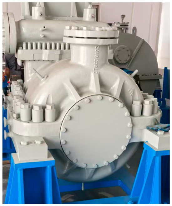
Figure 1.
Steam turbine exhaust chamber test facility.
The exhaust hood is designed as a cylindrical flow structure. The steam enters the exhaust cylinder from the last flow channel, and the flow direction changes from axial flow to radial flow to form a complex three-dimensional flow field.
To conduct a thermodynamic and flow field analysis of the last stage–exhaust hood coupled model, we established a 3D model of the coupled flow field of the last stage and the exhaust hood. In this section, first, a fully 3D solid model of the last stage–exhaust hood flow field was established. The fluid domain included the last-stage blade cascade, which comprised stationary and moving blades. The last-stage blade cascade was arranged in an axially symmetric pattern. To reduce the number of grids and enhance computational efficiency, single passage calculation was used. However, considering the impact of the external shroud of the moving blade on aerodynamic performance, a combination of a single stationary blade passage and a full-circumference moving blade passage was used to more vividly display flow characteristics. The simulation model of the exhaust hood is shown in Figure 2.
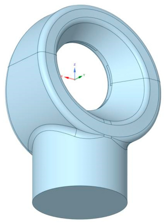
Figure 2.
The simulation model of the exhaust hood.
The coupled fluid domain included both the last-stage blades and the exhaust hood. Given the large size of the 1:1 scale model and its complex geometric structure, using structured grids alone is not conducive to grid division; however, using unstructured grids alone requires additional computer memory for storage. Therefore, this study used Turbo Grid R2022 to divide structured grids for the last-stage blade cascade. As a professional blade grid division software, Turbo Grid can divide a single passage and generate a full-circle channel by copying topology, significantly simplifying the blade grid division process. The unstructured grids had geometric adaptability; therefore, Fluent R2022 was used to divide unstructured grids for the exhaust hood. To ensure more accurate computational results, the model underwent grid independence verification. After setting the inlet flow and outlet pressure, a relatively coarse grid division calculation was first conducted, gradually refining the grid. Inlet pressure distribution was used for comparison; when the grid count exceeded 9 million, the numerical result error was within 5%, indicating insensitivity to the grid count at this point. The last-stage blades, shroud, exhaust hood inlet and outlet, reinforcing ribs, and some small walls were refined at a total grid count of approximately 11 million. The grid of the computational domain of the exhaust hood before and after structural optimization is shown in Figure 3.
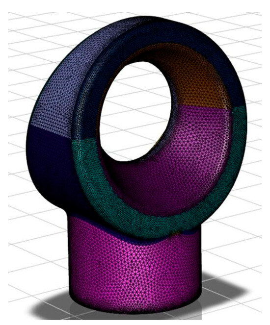
Figure 3.
Exhaust cylinder grid model.
Grid resolution correlates positively with computational accuracy and resource demand; hence, a grid-independence study is performed to achieve the optimal balance. Eight monitoring points are strategically placed at the last-stage blade exit (point R), exhaust volute (point C1-C4), and downstream diffuser (point E1-E3), as indicated in Figure 4.
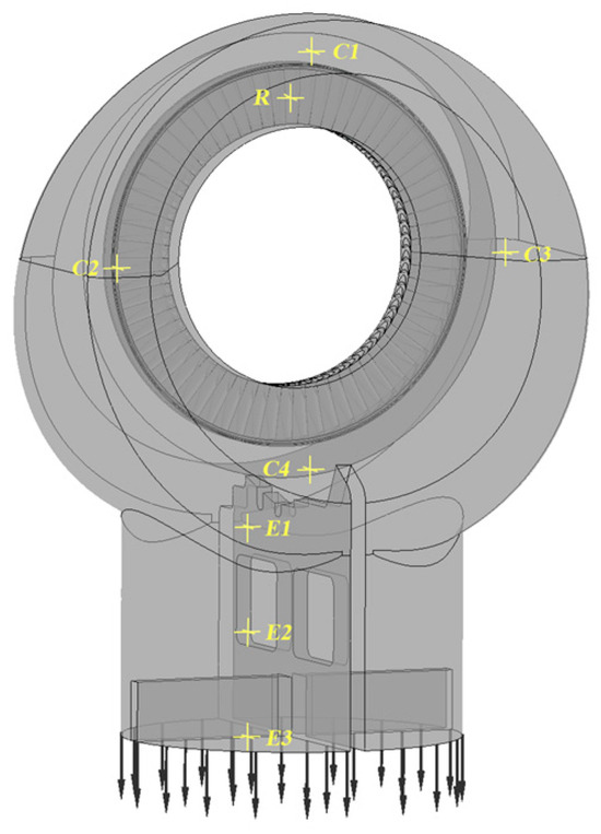
Figure 4.
Layout of monitoring points.
Four grid densities (7 Million, 9 Million, 11 Million, and 13 Million elements) are evaluated. Local refinement is applied to the last-stage blades, shrouds, exhaust-hood inlet/outlet, stiffening ribs, and near-wall regions. The average static pressure at the first monitoring point of each zone is adopted as the convergence criterion. The static pressure variation of each monitoring point is shown in Figure 5.
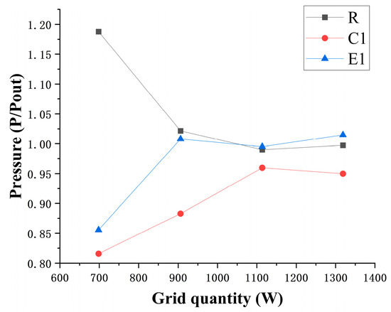
Figure 5.
Static pressure variation diagram of each monitoring point.
Relative errors remain below 5% for all probes once the grid count exceeds 11 M, confirming grid independence. Consequently, a total of approximately 11 million cells is adopted for all subsequent simulations.
2.3. Boundary Conditions
The boundary conditions of the calculated rated working conditions in this study are shown in Table 1.

Table 1.
Rated working condition boundary conditions.
2.4. Flow Field Performance Evaluation Parameters
To assess the thermodynamic performance of the exhaust hood, general indicators such as the static pressure recovery coefficient (), total pressure loss coefficient (), and cross-sectional velocity non-uniformity () were introduced. These are used as criteria for evaluation, and they are expressed as follows:
Ps denotes the static pressure at a certain point, and are the average static pressures at the inlet and outlet of the exhaust hood, and and are the average total pressures at the inlet and outlet of the exhaust hood, respectively. is the actual velocity at the i-th measurement point of a certain cross-section, and is the average velocity when the flow field is uniform at the cross-section.
A larger value indicated that the exhaust hood posed less resistance to the steam flow and had better pressure recovery effects. A higher value suggested greater pressure losses of the steam flow in the exhaust hood, that is, more energy loss of the steam flow in the exhaust hood. A smaller value indicated a more uniform velocity of the gas flow across the cross-section of the exhaust hood.
3. Structural Optimization Design of Exhaust Chambers
In this steam turbine configuration, the last stage lacks shrouds and the exhaust hood incorporates no stiffeners. Prototype testing has revealed significant steam flow losses and distinctive vibration signatures induced by flow excitation within the exhaust hood region. The flow state exiting the last-stage outlet is the primary driver influencing the thermo-aerodynamic behavior of the exhaust hood structure and exciting flow-induced vibrations. Consequently, structural enhancement of the integrated last stage–exhaust hood system is imperative.
3.1. Blade Tip Shroud Optimization
A full-annulus, self-locking shroud is installed at the rotor blade tips (Figure 6).The red circle part is the schematic diagram of the cross section of the self-locking shroud. By interconnecting adjacent blades into a continuous band, the shroud significantly increases flexural rigidity and overall blade strength. This configuration effectively suppresses detrimental vibrations—including flutter—induced by high centrifugal and aerodynamic excitation forces, particularly under wet-steam conditions. Inter-blade friction within the shrouded group provides additional aerodynamic damping, markedly enhancing operational safety and reliability.
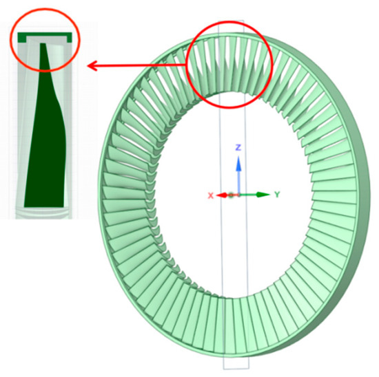
Figure 6.
Self-locking shroud structure model.
Furthermore, labyrinth-seal fins machined on the shroud tip engage with matching stator teeth to create a multi-stage throttling path. This arrangement drastically reduces high-pressure steam leakage across the tip clearance, thereby lowering internal leakage losses and substantially improving the aerodynamic efficiency of the last stage, as well as the overall economic performance of the unit.
3.2. Stiffener Optimization for Diffuser Section of Exhaust Chamber
Stiffening ribs are welded or integrally cast on the inner surface of the exhaust-hood diffuser (Figure 7) to provide structural strength and rigidity. Owing to the high specific volume and velocity of the last-stage exhaust steam, the diffuser must adopt a gradually expanding geometry to efficiently convert kinetic energy into pressure energy, thereby establishing and maintaining a high vacuum at the condenser inlet.
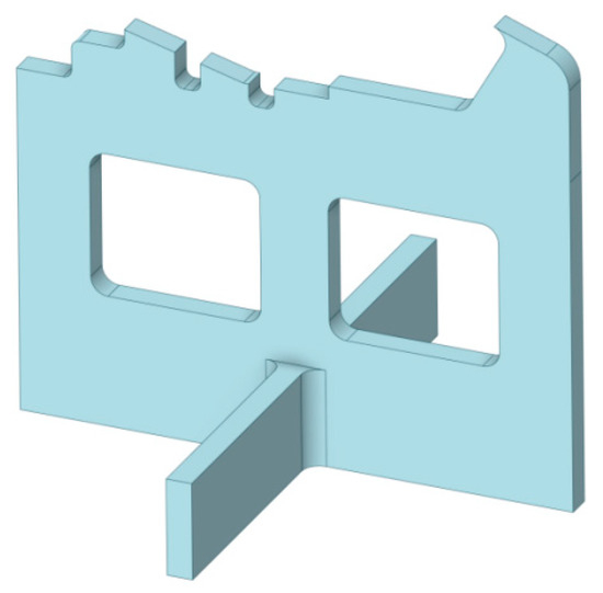
Figure 7.
Cruciform stiffener structural model for the diffuser section.
The resulting large, thin-walled cavity is subjected to significant differential pressure loads generated by the internal vacuum. Without adequate reinforcement, the diffuser is prone to deformation, instability, and harmful vibrations. The ribs, arranged in a rational pattern, form a robust skeletal framework that effectively resists these pressure loads, prevents collapse or excessive distortion, and suppresses detrimental vibrations. Consequently, the aerodynamic contour of the diffuser remains stable, the condenser vacuum is preserved, and the safe and efficient operation of the steam turbine is ensured.
Changes in the steam turbine’s last stage–exhaust hood structure directly impacted its thermodynamic performance and flow field. Thereafter, we conducted an in-depth comparative analysis of the thermodynamic and variable condition flow characteristics of the last stage–exhaust hood coupled structure before (without shroud and reinforcing ribs, as shown in Figure 8a) and after optimization (with shroud and reinforcing ribs, as shown in Figure 8b).
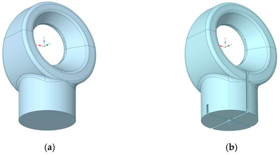
Figure 8.
Three-dimensional model of the last stage–exhaust hood flow field (a) before and (b) after optimization.
4. Analysis of Thermal and Flow Field Characteristics of the Last Stage–Exhaust Hood Coupled Model
4.1. Original Last Stage–Exhaust Hood Coupled Model
Under design conditions, the measured steam flow rate was G0. The pressure before the last stage and the exhaust pressure were considered as boundary conditions, and numerical calculations of the last stage–exhaust hood flow field were carried out. The calculated steam flow rate was determined to be G1 = 0.963 × G0, and it resulted in a calculation error of 3.72% in the steam flow rate. This indicated that the last stage–exhaust hood coupled model and CFD numerical calculation method established satisfied the requirements for analysis.
Figure 9 presents the three-dimensional streamlines of the baseline model under strong coupling between the free last-stage blades and the exhaust hood. Steam enters through the stator inlet and is accelerated by the last-stage stator blades; owing to blade curvature and stagger angle, it emerges as a swirling jet into the exhaust hood. Under the combined action of fluid inertia and viscous forces within the scroll, a pronounced channel vortex forms at the junction between the volute and the diffuser. Flow in the upper scroll travels as a channel vortex along both sidewalls before merging and mixing with the lower stream. A high-velocity region on the inner surface of the scroll generates significant flow-induced excitation. Guided by the turning vanes, the flow transitions from the axial to the radial direction, establishing the dominant channel vortex within the exhaust passage. The steam then decelerates progressively through the diffuser and exits the exhaust hood.
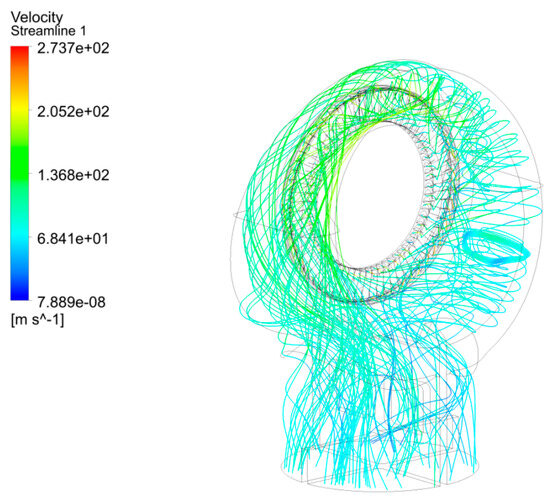
Figure 9.
Three-dimensional streamline of original exhaust hood.
The steam gradually decelerated in the exhaust hood and exited through the diffuser section. Therefore, the inlet boundary condition of the steam at the outlet of the stationary blades significantly impacted the flow field in the exhaust hood. Shrouds were installed at the top of the moving blades to minimize steam leakage losses at the moving blade tip, and this also improved steam flow. Flow field analysis revealed that there was a high degree of consolidation in the last stage–exhaust hood of compact steam turbines, along with complex steam flow excitation. This steam flow excitation significantly impacted the thin walls of the exhaust hood diffuser section and its vibration stability; this necessitated the addition of reinforcing ribs in the diffuser section of the last stage–exhaust hood. The introduction of reinforcing ribs in the flow field changed its characteristics, making it essential to study the impact of installing cross-shaped reinforcing ribs on the flow field characteristics.
4.2. Influence of Shroud on Coupled Flow Field of the Last Stage–Exhaust Hood
In this section, the coupled flow field of the exhaust hood was simulated with and without a shroud on the last-stage blades under the same inlet flow rate and outlet pressure boundary conditions. Under the same flow input conditions, the flow rate at the outlet of the shrouded moving blade was 4.7% higher than that of the non-shrouded blade, indicating that installing the shroud decreased steam flow losses at the blade tip, and the simulation results were more closely aligned with the numerical results. The performance of the exhaust hood before and after the shroud was installed is presented in Table 2.
Table 2.
Aerodynamic parameters of the exhaust hood before and after the shroud was installed.
After the shroud was installed, the exhaust hood’s efficiency increased and its inefficiencies decreased, demonstrating that the shroud effectively decreased inter-stage steam flow losses, enhanced the static pressure recovery capability of the exhaust hood, and improved its aerodynamic performance.
Figure 10 presents pressure contour diagrams at the outlet of the last-stage blades with and without the shroud coupled. Figure 11 shows pressure distribution curves at the outlet of the last-stage blades; these were taken from the same horizontal cross-section through the shaft center.
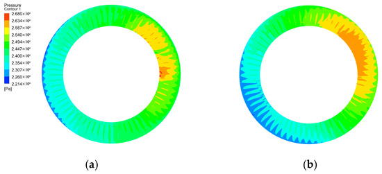
Figure 10.
Last-stage blades outlet pressure contour diagrams: (a) without shroud; (b) with shroud.
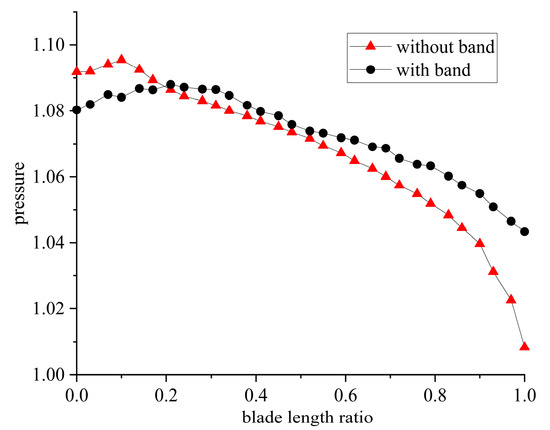
Figure 11.
Last-stage blades outlet pressure distribution curves.
As depicted in Figure 10b, the installation of a blade-tip shroud results in a marked contraction of the high-pressure region at the rotor exit and a 12.3% reduction in pressure non-uniformity. Compared to the last stage without the shroud, the last stage with the shroud had a lower pressure variation range at the outlet of the moving blades. This decreased the asymmetry in the steam exhaust of the last stage and resulted in more uniform pressure distribution.
Figure 12 displays the distribution of turbulence kinetic energy in the exhaust hood flow field. The last stage without the shroud exhibited higher turbulence kinetic energy on the side walls of the exhaust hood volute. This was primarily because the steam flow directly impacted the exhaust hood volute after it was discharged from the last stage; this resulted in increased local turbulence intensity and greater likelihood of significant steam flow excitation effects. After the shroud was added to the last stage, the turbulence kinetic energy on the volute decreased significantly, resulting in a more uniform steam flow.
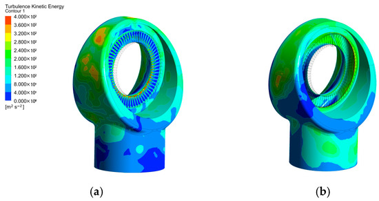
Figure 12.
Exhaust hood flow field turbulence kinetic energy contour diagrams: (a) without shroud; (b) with shroud.
Figure 13 shows the streamlines in the exhaust hood at a cross-section perpendicular to the axial direction. The steam flow from the last stage entered the exhaust hood volute at a certain angle and curled along the volute’s topology toward the diffuser of the exhaust hood. In the original structure, noticeable vortex formation and flow separation occurred at the junction between the volute and the diffuser. However, after optimizing the volute, these phenomena of vortex formation and flow separation were suppressed to some extent.
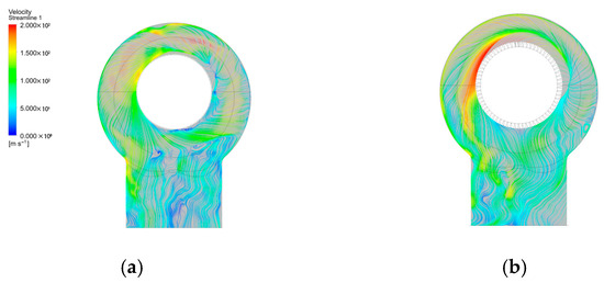
Figure 13.
Plane streamline diagram of the exhaust hood: (a) without shroud; (b) with shroud.
4.3. Influence of Reinforcing Ribs on Coupled Flow Field of the Last Stage–Exhaust Hood
In this section, simulations were conducted on the exhaust hood coupled model before and after the reinforcing ribs were installed; this was performed based on the last-stage blades with the shroud under the same inlet flow rate and outlet pressure boundary conditions.
Figure 14 and Figure 15 show the streamline diagrams of the exhaust hood diffuser at the horizontal mid-plane and the exhaust hood outlet before and after the installation of reinforcing ribs, respectively. Analysis of these diagrams revealed that the flow lines in the horizontal mid-plane of the exhaust hood diffuser were roughly the same before and after the installation of the reinforcing ribs, indicating that the primary impact of the reinforcing ribs was concentrated at the exhaust hood outlet.
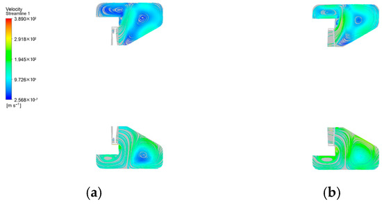
Figure 14.
Exhaust hood diffuser at the horizontal mid-plane streamline diagrams: (a) without reinforcing ribs; (b) with reinforcing ribs.
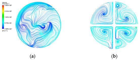
Figure 15.
Exhaust hood outlet streamline diagrams: (a) without reinforcing ribs; (b) with reinforcing ribs.
In the original model, the flow state at the exhaust hood outlet was complex, and there were collisions and mixtures of streams in various directions. After the reinforcing ribs were installed, steam at the outlet formed four main passage vortices, and it was divided into separate sections. In each section, there were vortices of varying intensities. The presence of these vortices increased the circumferential energy dissipation in the exhaust hood chamber, which hindered the axial transfer of energy. This increased energy dissipation led to greater energy losses and decreased the flow capacity of the exhaust hood.
After calculations, the performance of the exhaust hood without and with reinforcing ribs is shown in Table 3.
Table 3.
Aerodynamic parameters of the exhaust hood before and after the installation of reinforcing ribs.
Installing cross-shaped reinforcing ribs disrupted the normal flow of steam and caused the steam to continuously mix and formed small, numerous vortices within the four separated regions as it descended. Installing the reinforcing ribs decreased the efficiency, increased the inefficiency, decreased the static pressure recovery capability of the exhaust hood, increased the pressure loss, and negatively influenced the exhaust hood’s flow efficiency.
Figure 16 shows the velocity distribution contour diagrams at the exhaust hood outlet before and after installing the reinforcing ribs. Because of the reinforcing ribs, a smoother trend in the decrease in steam velocity was observed at the exhaust hood outlet. Sixteen measurement points were randomly selected at the same positions at the outlet of both models to measure the velocity non-uniformity at the outlet cross-section. The velocity non-uniformity at the exhaust hood outlet without reinforcing ribs was 0.605, and with cross-shaped reinforcing ribs installed, it was 0.427. This indicated that installing the cross-shaped reinforcing ribs led to a more uniform distribution of steam velocity at the outlet, and this was beneficial for the steam entering the condenser from the exhaust hood.
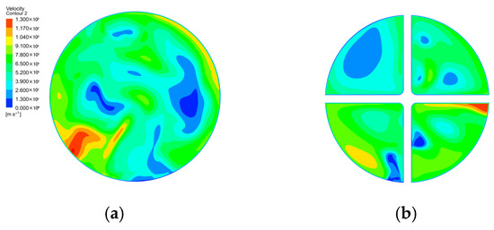
Figure 16.
Exhaust hood outlet velocity contour diagrams: (a) without reinforcing ribs; (b) with reinforcing ribs.
Thus, we concluded that coupling the last-stage blades with the shroud and the exhaust hood with cross-shaped reinforcing ribs considered the influence of the last-stage blades on the exhaust hood, and the results were thus more realistic. Reinforcing ribs were also added to the existing model. Next, we conducted an analysis of the flow field of the exhaust hood under different operating conditions with a shroud as well as reinforcing ribs and evaluated the impact of structural optimization on the exhaust hood.
5. Analysis of Flow Field Characteristics of the Last Stage–Exhaust Hood Coupled Model Under Varying Conditions
5.1. Last Stage–Exhaust Hood Flow Field Under Different Flow Conditions
Marine steam turbines often operate under varying and complex sea conditions, and different steam flow rates enter the turbine depending on the operating state. In this section, the coupled flow field of the last stage–exhaust hood was analyzed under three flow conditions, that is, 10, 50, and 100% of the design flow rate; the same outlet pressure conditions were considered while the inlet flow rate was varied.
Figure 17 presents the streamline diagrams at different blade heights within the last-stage blades under three conditions. Figure 18 shows the pressure variation curves at different blade heights at the outlet of the last-stage blades under these conditions. At a 10% flow rate, a few vortices were formed near the hub of the last-stage blades. The pressure range at the blade outlet was between 0.985 and 1.010, with a pressure variation magnitude of 0.025. At a 50% flow rate, vortices formed inside the last-stage blades were not significantly different from those at a 10% flow rate, the pressure range at the blade outlet was between 1.026 and 1.063, and the pressure variation magnitude was 0.037. In the 100% flow rate condition, the steam exhibited better flow characteristics inside the last-stage blades, and the pressure range at the blade outlet was between 1.097 and 1.208, and the pressure variation magnitude was 0.111. As the flow rate increased, the outlet pressure of the last stage gradually increased, and the pressure variation magnitude increased, leading to enhanced pressure non-uniformity.
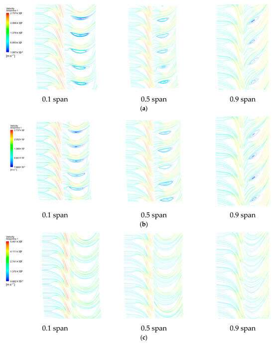
Figure 17.
Streamline diagrams at different blade span within the last-stage blades under three flow conditions: (a–c) 10, 50, and 100%, respectively.
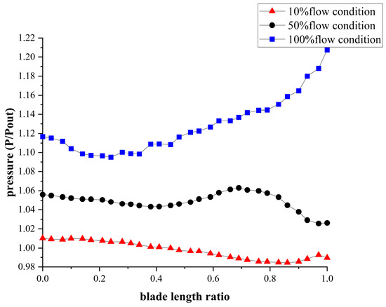
Figure 18.
Pressure variation curves at different blade span within the last-stage blades under three flow conditions.
Figure 19 shows the turbulence kinetic energy variation curves at different blade heights in the last-stage blades under the three flow conditions. At a 10% flow rate, the turbulence kinetic energy was less at the blade root and tip but high at the middle of the blade, which indicated significant turbulence. At a 50% flow rate, the turbulence kinetic energy was relatively low across the entire blade outlet. However, at a 100% flow rate, the turbulence kinetic energy was high at the blade root and tip but low in the middle, suggesting that at high flow rates, the blade root and tip influenced the steam flow, leading to energy losses. This model demonstrated better aerodynamic performance under the 50% flow rate condition.
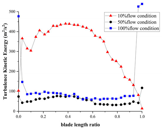
Figure 19.
Turbulence kinetic energy variation curves at different blade span within the last-stage blades under three flow conditions.
Figure 20 displays the streamlines starting from the inlet of the moving blades under the three flow conditions. Under low-flow conditions, steam underwent multiple axial rotations around the blades at the last-stage outlet. When merging with the upper steam flow and exiting, the flow of steam was hindered because of the presence of reinforcing ribs, causing energy dissipation. This resulted in a disordered flow state in the exhaust hood and was accompanied by backflow at the outlet. With an increase in the flow rate, numerous passage vortices formed inside the expander after the steam flowed through the last-stage blades. Under high-flow conditions, steam velocity was more perpendicular to the outlet. At a 100% flow rate, because of the high velocity of the steam flow, the reinforcing ribs created significant obstruction, generating vortices in the vertical direction. The cross-shaped reinforcing ribs had a more pronounced rectifying effect under high-flow conditions, but they also created four passage vortices at the outlet, which decreased the working efficiency of the exhaust hood to some extent.
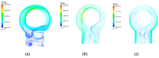
Figure 20.
Plane streamline diagram of the exhaust hood under three flow conditions: (a–c) 10, 50, and 100%, respectively.
According to the aerodynamic performance parameters of the exhaust hood under three different flow rate conditions (Table 4), with an increase in the input flow rate, for the 50% inlet flow rate condition, the static pressure recovery coefficient (cpsr) was >0, and the total pressure loss coefficient (cptl) was the lowest. For the other two conditions, the cpsr values were <0. This indicated that the exhaust hood lost its static pressure recovery capability when the inlet flow rate was either too low or too high, leading to an inability to recover the kinetic energy of the steam and resulting in significant pressure losses.
Table 4.
Aerodynamic parameters of the exhaust hood under three flow conditions.
Analysis of the aforementioned calculation results indicated that the coupled model of the last stage and the exhaust hood was significantly influenced by the steam inlet flow rate. Operation under the 50% flow rate condition was the most suitable.
5.2. Last Stage–Exhaust Hood Flow Field Under Different Outlet Pressure Conditions
Under varying operational conditions, the steam flow rate differed, and the exhaust pressure also varied accordingly. Therefore, this section primarily analyzed the flow field of the exhaust hood under three different exhaust pressure conditions, namely, 80, 100, and 120%, while maintaining a constant inlet flow rate of 50%.
Figure 21 displays the sectional streamline diagrams at different blade heights within the last-stage blades under the three conditions. Figure 22 shows the pressure variation curves at different blade heights at the last-stage blade outlet. Under the 80% exhaust pressure condition, there were very few vortices within the entire blade, indicating good flow characteristics. The pressure range at the blade outlet was between 1.062 and 1.136, and the pressure variation magnitude was 0.074. Under the 100% exhaust pressure condition, small vortices formed near the blade hub, and the pressure range at the blade outlet was between 1.026 and 1.063, with a pressure variation magnitude of 0.037. At the 120% exhaust pressure condition, larger vortices formed near the blade hub, and steam flow separation occurred in the middle of the blade back at the root. The interaction of these two factors affected the flow efficiency, and the pressure range at the blade outlet was between 0.985 and 1.022, with a pressure variation magnitude of 0.037. As the exhaust pressure increased, vortices formed within the blades became larger, the ratio of the outlet pressure of the last stage to the exhaust pressure decreased, and the flow effect worsened. Meanwhile, the pressure variation magnitude decreased, indicating a decrease in pressure non-uniformity.
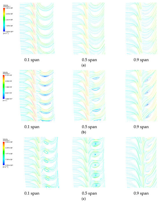
Figure 21.
Streamline diagrams at different blade spans within the last-stage blades under three outlet pressure conditions: (a–c) 80, 100, and 120%, respectively.
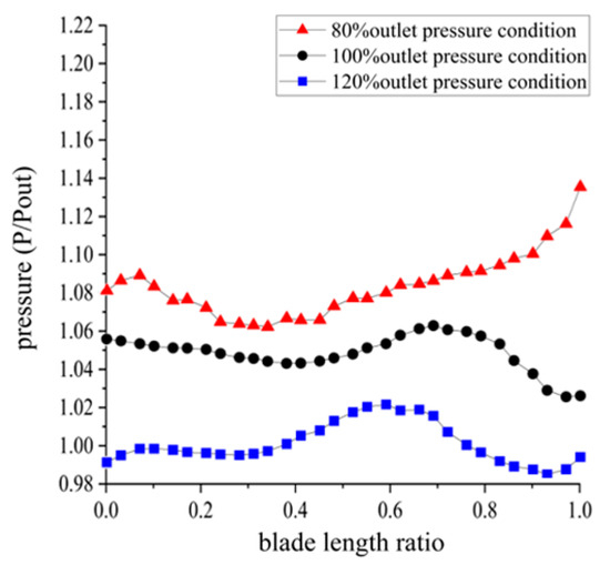
Figure 22.
Pressure variation curves at different blade spans within the last-stage blades under three outlet pressure conditions.
Figure 23 shows the turbulence kinetic energy variation curves at different blade heights within the last-stage blades under the three conditions. Under the 80% exhaust pressure condition, the turbulence kinetic energy was higher at the blade root and tip, indicating significant turbulence. At the 100% exhaust pressure condition, the turbulence kinetic energy was relatively low across the entire blade outlet. Under the 120% exhaust pressure condition, the turbulence kinetic energy was higher at the blade root and lower at the tip, suggesting that under low or excessively high exhaust pressure, strong turbulence occurred at the blade root, causing significant energy loss. Notably, under low exhaust pressure conditions, turbulence also occurred at the blade tip. The best aerodynamic performance was achieved under the 100% exhaust pressure condition.
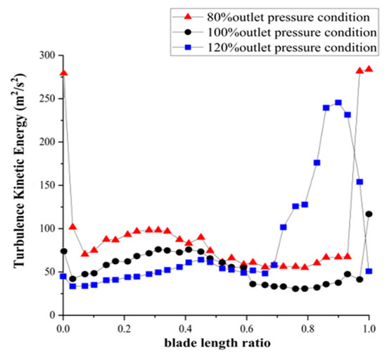
Figure 23.
Turbulence kinetic energy variation curves at different blade span within the last-stage blades under three outlet pressure conditions.
Figure 24 presents the sectional streamline diagrams starting from the inlet of the moving blades under the three exhaust pressure conditions. Under low exhaust pressure conditions at the exhaust hood outlet, steam was more uniformly distributed. As the outlet pressure increased to 100%, the vertical flow of steam improved. With further increase in the exhaust pressure, as shown in Figure 14, the pressure difference between the inlet and outlet of the exhaust hood decreased, intensifying energy dissipation within the exhaust hood and progressively forming a large amount of turbulence.
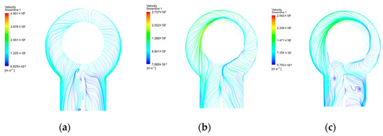
Figure 24.
Plane streamline diagram of the exhaust hood under three outlet pressure conditions: (a–c) 80, 100, and 120%, respectively.
Table 5 presents the aerodynamic performance parameters of the exhaust hood for the last-stage blades under three different exhaust pressure conditions. At 100% exhaust pressure, the cpsr of the exhaust hood was >0, and the cptl was the lowest. In contrast, under the other two conditions (80 and 120% exhaust pressure), the cpsr was <0. This indicated that the exhaust hood lost its static pressure recovery capability when the exhaust pressure was either too low or too high.
Table 5.
Aerodynamic parameters of the exhaust hood under three outlet pressure conditions.
6. Conclusions
- The three-dimensional last stage–exhaust hood coupled model and numerical framework developed in this study accurately resolve the flow characteristics within the stator cascade, rotor passages, upper/lower scrolls, and diffuser; results agree with prototype measurements to within 4% in mass flow prediction, confirming the model’s suitability for off-design analyses.
- Shroud optimization raises the static pressure recovery coefficient by 11.5% and reduces the total pressure loss coefficient by 2.3%. It simultaneously attenuates turbulence kinetic energy in the scroll and blade rows, enhances rotor vibration stability, smooths the exhaust-scroll flow, and suppresses transition-region vortices and flow separation.
- Stiffening ribs significantly increase exhaust-hood rigidity, produce a more uniform stress field, and mitigate flow-induced vibrations. Nevertheless, they reduce exit-flow non-uniformity at the expense of a lower static pressure recovery coefficient and higher total pressure losses. Future work will focus on rib-shape optimization to reconcile structural stiffness with aerodynamic performance.
- Numerical assessments of the optimized exhaust hood across a broad operating envelope reveal that both excessively low and high inlet flows degrade aerodynamic performance; the 50% mass flow and 100% exhaust pressure conditions constitute the optimum, with rapid deterioration observed outside this range. Active-control strategies, such as adjustable guide vanes, merit further investigation.
Author Contributions
Conceptualization, L.Z.; Methodology, L.Z.; Software, Y.S. and L.X.; Validation, Y.S. and Y.Z.; Data curation, Y.S.; Writing—original draft, Y.S. and L.X.; Writing—review & editing, L.Z., Y.Z. and Z.Y.; Supervision, Z.Y. All authors have read and agreed to the published version of the manuscript.
Funding
This research received no external funding.
Data Availability Statement
Data are contained within the article.
Conflicts of Interest
The authors declare no conflict of interest.
Glossary
| CFD | Computational fluid dynamics |
| SST | Shear stress transport |
| U | Velocity |
| Cpsr | Static pressure recovery coefficient |
| Cptl | Total pressure loss coefficient |
| Cross-sectional velocity non-uniformity | |
| Inlet average static pressures | |
| Outlet average static pressures | |
| Inlet average total pressures | |
| Outlet average total pressures | |
| Average velocity |
References
- Burton, Z.; Ingram, G.L.; Hogg, S. A Literature Review of Low Pressure Steam Turbine Exhaust Hood and Diffuser Studies. J. Eng. Gas Turbines Power 2013, 135, 062001. [Google Scholar] [CrossRef]
- Veerabathraswamy, K.; Senthil Kumar, A. Effective Boundary Conditions and Turbulence Modeling for the Analysis of Steam Turbine Exhaust Hood. Appl. Therm. Eng. 2016, 103, 3–80. [Google Scholar] [CrossRef]
- Cai, L.; Xiao, J.; Wang, S.; Gao, S.; Duan, J.; Mao, J. Gas-Particle Flows and Erosion Characteristic of Large Capacity Dry Top Gas Pressure Recovery Turbine. Energy 2017, 120, 498–506. [Google Scholar] [CrossRef]
- Munyoki, D.; Schatz, M.; Vogt, D.M. Numerical Investigation of the Influence of Hood Height Variation on Performance of Low Pressure Steam Turbine Exhaust Hoods. In Proceedings of the SME Turbo Expo 2018: Turbomachinery Technical Conference and Exposition, Power for Land, Sea, and Air, Oslo, Norway, 11–15 June 2018. [Google Scholar]
- Tabata, S.; Fukushima, H.; Segawa, K.; Ishibashi, K.; Kuwamura, Y.; Sugishita, H. Experimental and Numerical Investigations of Steam Turbine Exhaust Hood Flow Field with Two Types of Diffusers. In Proceedings of the ASME Turbo Expo 2019: Turbomachinery Technical Conference and Exposition, Power for Land, Sea, and Air, Phoenix, AZ, USA, 17–21 June 2019. [Google Scholar]
- Cao, L.; Li, L.; Hu, B.; Si, H.; Hu, P. Aerodynamic Performance Change of Exhaust Passage in Steam Turbine under Low-Load Conditions. Int. J. Heat Mass Transf. 2020, 157, 119929. [Google Scholar] [CrossRef]
- Sadasivan, S.; Arumugam, S.K.; Aggarwal, M.C. Computational Investigation of Multi-Phase Flow Effects on the Performance of the Steam Turbine Exhaust Hood. Proc. Inst. Mech. Eng. Part A J. Power Energy 2021, 235, 279–290. [Google Scholar] [CrossRef]
- Tupy, D.; Slama, V.; Kalista, R.; Pulec, J.; Novosad, J.; Dančová, P. Experimental Research on the Flow in the Steam Turbine Axial Exhaust Hood. In Proceedings of the EPJ Web of Conferences, Busan, Republic of Korea, 13–17 June 2022. [Google Scholar]
- Ercan, I.; Vogt, D.M. Analysis of Turbulent Effects in a Low-Pressure Model Steam Turbine Operating under Various Operating Conditions Using Detached Eddy Simulation. In Proceedings of the ASME Turbo Expo 2022: Turbomachinery Technical Conference and Exposition, Power for Land, Sea, and Air, Rotterdam, The Netherlands, 14–16 June 2022. [Google Scholar]
- Fomina, A.; Fuhrer, C.; Vogt, D.M.; Willeke, T. Numerical Study on the Influence of Geometrical Parameters on the Performance of a Turbine Exhaust Hood. In Proceedings of the ASME Turbo Expo 2023: Turbomachinery Technical Conference and Exposition, Power for Land, Sea, and Air, Boston, MA, USA, 26–30 June 2023. [Google Scholar]
- Zhang, L.; Congiu, F.; Gan, X.; Karunakara, D. Performance Prediction and Optimization of Low Pressure Steam Turbine Radial Diffuser at Design and Off-Design Conditions Using Streamline Curvature Method. J. Eng. Gas Turbines Power 2017, 139, 072601. [Google Scholar] [CrossRef]
- Weixue, C.; Xueyi, Y. The Inverse Optimization of Exhaust Hood by Using Intelligent Algorithms and CFD Simulation. Powder Technol. 2017, 315, 282–289. [Google Scholar] [CrossRef]
- Gribin, V.G.; Paramonov, A.N.; Mitrokhova, O.M. The Effect of Condensing Steam Turbine Exhaust Hood Body Geometry on Exhaust Performance Efficiency. Therm. Eng. 2018, 65, 371–378. [Google Scholar] [CrossRef]
- Galaev, S.A.; Ris, V.V.; Smirnov, E.M.; Babiev, A.N. Experience Gained from Designing Exhaust Hoods of Large Steam Turbines Using Computational Fluid Dynamics Techniques. Therm. Eng. 2018, 65, 352–361. [Google Scholar] [CrossRef]
- Kandasamy, V.; Arumugam, S.K. Design Optimization of Multi-Kink Axial Radial Diffuser of Steam Turbine Exhaust Hoods. J. Eng. Sci. Technol. 2019, 14, 1088–1100. [Google Scholar]
- Cao, L.; Li, L.; Dong, E.; Si, H.; Ning, Z.; Liu, M. Influence of Aerodynamic Characteristics Optimization of Exhaust Passage on Heat Transfer of Condenser in Steam Turbine. Energy 2019, 188, 116094. [Google Scholar] [CrossRef]
- Xu, Q.; Lin, A.; Cai, Y.; Ahmad, N.; Duan, Y.; Liu, C. Numerical Analysis of Aerodynamic Characteristics of Exhaust Passage with Consideration of Wet Steam Effect in a Supercritical Steam Turbine. Energies 2020, 13, 1560. [Google Scholar] [CrossRef]
- Doll, P.; Müller, F.F.; Schippling, S.; Vogt, D.M.; Aschenbruck, J. Influence of a Rib in the Diffuser of a Low-Pressure Steam Turbine on Aerodynamic Excitation at Part Load Operation. In Proceedings of the ASME Turbo Expo 2023: Turbomachinery Technical Conference and Exposition, Power for Land, Sea, and Air, Boston, MA, USA, 26–30 June 2023. [Google Scholar]
- Song, Z.; Xu, J.Q.; Sun, L.P.; Liu, M.T. Study of Coupling Numerical Flow Field Simulation of Low-Pressure Last Stage Exhaust Passage in Steam Turbine. Appl. Mech. Mater. 2014, 672, 26–32. [Google Scholar] [CrossRef]
- Stein, P.; Pfoster, C.; Sell, M.; Galpin, P.; Hansen, T. CFD Modeling of Low Pressure Steam Turbine Radial Diffuser Flow by Using a Novel Multiple Mixing Plane Based Coupling, Simulation and Validation. In Proceedings of the ASME Turbo Expo 2015: Turbomachinery Technical Conference and Exposition, Power for Land, Sea, and Air, Montreal, QC, Canada, 15–19 June 2015. [Google Scholar]
- Cao, L.; Lin, A.; Li, Y.; Xiao, B. Optimum Tilt Angle of Flow Guide in Steam Turbine Exhaust Hood Considering the Effect of Last Stage Flow Field. Chin. J. Mech. Eng. 2017, 30, 866–875. [Google Scholar] [CrossRef]
- Cao, L.; Si, H.; Lin, A.; Li, P.; Li, Y. Multi-Factor Optimization Study on Aerodynamic Performance of Low-Pressure Exhaust Passage in Steam Turbines. Appl. Therm. Eng. 2017, 124, 224–231. [Google Scholar] [CrossRef]
- Mitrokhova, O.; Gribin, V.; Paramonov, A.; Guryanova, A.; Revenko, A. Numerical Simulation of 3d Flow in the Diffuser Exhaust Hood of the High-Power Steam Turbine. In Proceedings of the 18th Conference of Power System Engineering, Thermodynamics and Fluid Mechanics, Pilsen, Czech Republic, 11–13 June 2019; AIP Publishing: Melville, NY, USA, 2019. [Google Scholar]
- Fondelli, T.; Diurno, T.; Palanti, L.; Andreini, A.; Facchini, B.; Nettis, L.; Arcangeli, L.; Maceli, N. Investigation on Low-Pressure Steam Turbine Exhaust Hood Modelling through Computational Fluid Dynamic Simulations. In Proceedings of the 74th ATI National Congress: Energy Conversion: Research, Innovation and Development for Industry and Territories, Modena, Italy, 11–13 September 2019; AIP Publishing: Melville, NY, USA, 2019. [Google Scholar]
- Mambro, A.; Congiu, F.; Galloni, E.; Canale, L. Experimental Study and Modelling of the Ventilation Power and Maximum Temperature of Low-Pressure Steam Turbine Last Stages at Low Load. Appl. Energy 2019, 241, 59–72. [Google Scholar] [CrossRef]
- Jiang, X.; Lin, A.; Malik, A.; Chang, X.; Xu, Y. Numerical Investigation on Aerodynamic Characteristics of Exhaust Passage with Consideration of Multi-Factor Components in a Supercritical Steam Turbine. Appl. Therm. Eng. 2019, 162, 114085. [Google Scholar] [CrossRef]
- Sadasivan, S.; Arumugam, S.K.; Aggarwal, M.C. An Alternative Numerical Model for Investigating Three-Dimensional Steam Turbine Exhaust Hood. J. Appl. Fluid Mech. 2020, 13, 639–650. [Google Scholar] [CrossRef]
- Wang, X.; Zhu, Y.; Li, W.; Zhang, X.; Chen, H. Flow Characteristics of an Axial Turbine with Chamber and Diffuser Adopted in Compressed Air Energy Storage System. Energy Rep. 2020, 6, 45–57. [Google Scholar] [CrossRef]
- Diurno, T.; Fondelli, T.; Nettis, L.; Maceli, N.; Arcangeli, L.; Andreini, A.; Facchini, B. Numerical Investigation on the Aerodynamic Performance of a Low-Pressure Steam Turbine Exhaust Hood Using Design of Experiment Analysis. J. Eng. Gas Turbines Power 2020, 142, 111006. [Google Scholar] [CrossRef]
- Diurno, T. Aerodynamic Investigation of Steam Turbine Exhaust System through CFD Modelling, Design Performance Optimization and Off-Design Assessment. Ph.D. Thesis, University of Florence, Florence, Italy, 2022. [Google Scholar]


Disclaimer/Publisher’s Note: The statements, opinions and data contained in all publications are solely those of the individual author(s) and contributor(s) and not of MDPI and/or the editor(s). MDPI and/or the editor(s) disclaim responsibility for any injury to people or property resulting from any ideas, methods, instructions or products referred to in the content. |
© 2025 by the authors. Licensee MDPI, Basel, Switzerland. This article is an open access article distributed under the terms and conditions of the Creative Commons Attribution (CC BY) license (https://creativecommons.org/licenses/by/4.0/).