1. Introduction
Previous research, such as the work of Jahan et al. [
1], shows that one of the key factors in reducing the cycle time of an injection molding process—and thereby increasing its productivity—is the ability to effectively cool both halves of the mold, as well as any inserts used to create internal cavities. Efficient cooling allows for faster ejection of the molded part without deformation. However, traditional cooling channels are limited by the constraints of conventional machining, which prevent the implementation of geometrically optimized cooling solutions. In some cases, inserts may be too small to be machined with internal cooling channels, further reducing thermal efficiency.
Works such as those developed by Jahan et al. [
2], Kirchheim et al. [
3] or Marques et al. [
4], agree that a promising solution to these limitations is the use of conformal cooling channels (CCCs), which can be adapted to the geometry of the molded part and positioned closer to functional surfaces of the mold. This approach improves heat dissipation, enabling a shorter cycle time without compromising part quality. Additionally, CCCs allow for greater design flexibility, making it feasible to produce thicker injection-molded parts without significantly increasing cycle time.
To manufacture molds with integrated CCCs more affordably, alternative metal AM technologies must be considered. As established in the work of Parenti et al. [
5], in which different technical and economic aspects of influence are analyzed to develop a decision system to select the appropriate metal AM technology, Metal-Fused Filament Fabrication (Metal-FFF) is an additive manufacturing (AM) technology that provides a simpler and more cost-effective alternative to other metal AM techniques, such as Laser Powder Bed Fusion (LPBF). Metal-FFF enables the production of complex geometries that are difficult or impossible to achieve through conventional machining. However, the process involves a debinding and sintering stage, in which the printed part shrinks by approximately 20% when using commercial filaments, posing challenges for dimensional accuracy. Limitations that became evident in works such as those developed by Ait-Mansour et al. [
6], focused on the predicting the influence of infill level and build orientations on shrinkage behavior to adapt the original design of the part, or Quarto el al. [
7], in which parameters such as infill pattern, extrusion speed or layer thickness are analyzed to evaluate their influence on dimensional shrinkage and bulk density in metal FDM parts.
CCCs have been extensively studied and proven to enhance thermal efficiency in injection molding. However, almost all research and industrial applications have focused on LPBF, a high-cost technology that requires specialized equipment and significant material investment, as established in the work of Parenti et al. [
5]. Despite LPBF’s superior precision, injection molds still require post-processing machining to meet the strict dimensional tolerances and surface roughness requirements necessary for successful molding operations. An aspect that can be seen in different works focused on improving the manufacturing of conformal cooling channels for injection molds using metal AM thechnologiessuch as the ones developed by Marin et al. [
8], Oh et al. [
9] or Mazur et al. [
10]. This raises an important question: if post-processing is always required, could Metal-FFF be a more cost-effective alternative?
This study aims to confirm the feasibility of Metal-FFF as a method to produce functional injection molds incorporating CCCs as a proof of concept. By leveraging the lower cost of Metal-FFF while acknowledging that post-processing is inevitable, this research investigates whether Metal-FFF can achieve the same benefits as LPBF-based molds but at a fraction of the cost. It does not seek to close a comprehensive knowledge gap; rather, it tests basic feasibility and value, providing a starting point for deeper studies. The project consists of the design, fabrication, and experimental validation of a mold manufactured using Metal-FFF.
The key steps in this study include optimizing the design of CCCs for both halves of the mold and adapting the geometry to the constraints of Metal-FFF, particularly taking into account the requirements of the sintering process. After fabrication, the mold undergoes post-sintering machining to achieve the dimensional tolerances necessary for successful injection molding. Additionally, functional elements such as cooling connections, ejectors, and attachment points are integrated to ensure proper mold operation. Once the mold is complete, injection molding trials are conducted to evaluate part quality and measure improvements in cycle time. The performance of the Metal-FFF mold is then compared to that of a conventionally machined mold with traditional cooling channels, allowing for an assessment of the potential benefits of conformal cooling.
2. Materials and Methods
2.1. Geometrical and Mold Design Considerations in Injection Molding
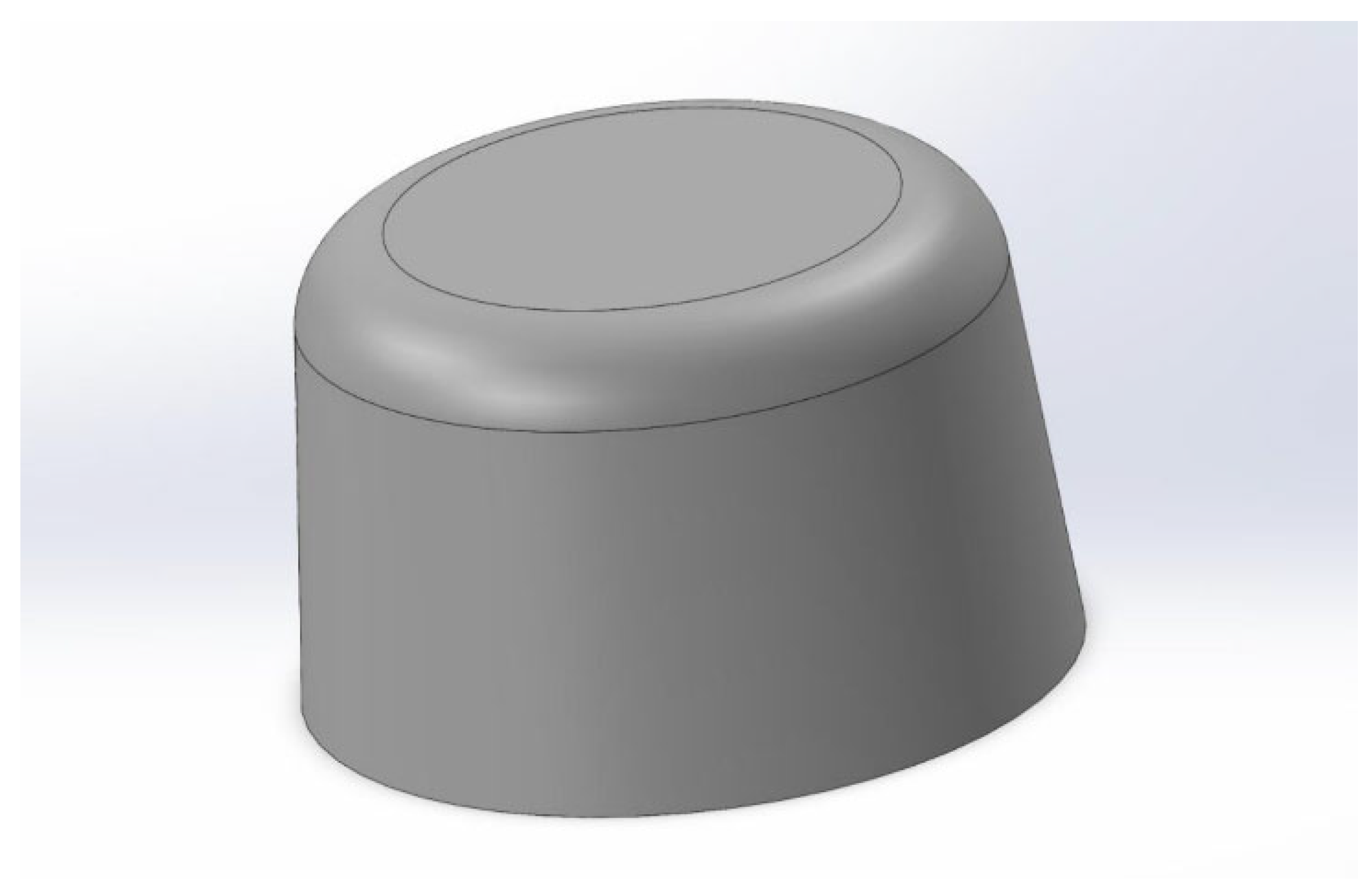
The design process begins with the selection and modeling of the plastic part to be injected: a 40 mm diameter plastic cap with a 5° draft angle to facilitate ejection and a 2.5 mm wall thickness, selected to ensure a sufficiently long cooling time for evaluating the impact of improved thermal performance, as seen in
Figure 1.
A symmetrical design was chosen to eliminate hot spots—regions where poor cooling could delay solidification. Previous research has extensively demonstrated that CCCs improve cooling performance, with various strategies explored based on geometry. Since CCCs have already been validated as an effective solution in prior studies, such as the works developed by Marin et al. [
8] or Mercado-Colmenero et al. [
11], this research focuses instead on verifying the feasibility of Metal-FFF for producing mold inserts and quantifying its performance compared to traditional cooling methods.
Traditionally, injection molds are manufactured by CNC machining the negative of the cavity directly into the mold halves. However, inserts are often used when complex geometries or deep cavities make direct machining impractical. Inserts also facilitate mold interchangeability, allowing for easy replacement and greater mold base utilization. Given the constraints of Metal-FFF, the most practical approach is to fabricate only the inserts using AM, rather than the entire mold. This strategy takes advantage of AM’s geometric flexibility to implement internal cooling channels while minimizing material use in non-critical mold areas, an approach adopted by authors such as Kirchheim et al. [
3] and Homar et al. [
12]. Additionally, as observed in the works of Quarto et al. [
7] and Tosto et al. [
13], Metal-FFF parts shrink during sintering, making full-mold fabrication impractical due to difficulties in maintaining dimensional accuracy.
Thus, both inserts were designed with an additional material allowance of 1 mm on each axis beyond their theoretical dimensions, ensuring that, after post-sintering machining, they meet the required tolerances for proper fit and function within the mold.
2.2. Insert Design
The interior insert was designed with an ascending helical cooling channel positioned beneath the functional surface. To avoid printing defects, a teardrop-shaped cross-section was chosen instead of a perfect circular channel, as seen in
Figure 2. This prevents overhangs exceeding 45°, a known threshold in AM that can lead to printing failures, and is a widely recommended design rule by filament manufacturers. The cooling system was finalized by mirroring and rotating the helical structure to create a descending spiral, connecting the inlet and outlet at the ends of the insert.
The exterior insert followed a similar design approach, though its geometric constraints required additional adjustments. Space had to be reserved in the center for machining the injection point, and due to thinner walls, the cooling channels had to be carefully positioned to maintain structural integrity.
The design of both inserts also required consideration of limitations associated with the Metal-FFF process. These are detailed in technical datasheets provided by filament manufacturers and relate primarily to the sintering stage. Key constraints include the final sintered part size, wall slenderness to prevent collapse under self-weight, and maximum thickness for proper debinding.
2.3. Material Selection and Design Optimization
Once the injected part has been selected and the general geometry of the inserts has been defined, the next step is to choose the most suitable printing material among those commercially available. This decision directly affects the mechanical and thermal performance of the inserts, especially under injection molding conditions.
A wide range of metal filaments are currently available for FFF, including 316 L stainless steel, 17-4 PH stainless steel, copper, bronze, aluminum 6061, tungsten, titanium Ti6Al4V, and H13 tool steel. Among these, BASF’s 17-4 PH stainless steel was selected for this study due to its balanced cost, ease of printing, and high mechanical strength. With a yield strength of up to 760 MPa, it is well suited for mold applications.
To adapt the insert geometry to the selected material and optimize its performance, Finite Element Analysis (FEA) was carried out in SolidWorks (
https://www.solidworks.com/). The goal was to determine the optimal channel diameter and wall thickness to maximize cooling density while ensuring mechanical reliability. Static strength analyses were performed by constraining the parts along the surfaces interfacing with the mold cavity and applying pressure loads to the functional surfaces. The applied pressure was based on an estimated clamping force of 20 tons exerted by the injection machine during the injection phase, distributed over the relevant contact areas. The parameters that varied in the simulations included CCC diameter, their distance from the mold surface, and the spiral pitch. A minimum safety factor of four with respect to the yield strength was set as the design constraint. The most favorable combination of these elements is shown in
Table 1 and
Figure 3.
2.4. Manufacturing Process
With the optimal design parameters defined and the printing material selected, the next stage in the process involved fabricating the inserts via Metal-FFF and performing post-processing operations to ensure dimensional accuracy and functional compatibility. This included 3D printing, sintering, precision machining, and final adjustments to integrate the inserts into the injection mold assembly.
Once the inserts were designed, they were exported as STL files and scaled by 20% in the XY plane and 26% in the Z axis, according to the manufacturer’s recommendations, to compensate for shrinkage during debinding and sintering. The parts were then printed using the parameters recommended by the manufacturer, as detailed in
Table 2, and underwent a standard sintering process performed by Elnik, BASF’s certified partner for these post-processing operations, ensuring a controlled and validated workflow. The result of this sintering process can be seen in
Figure 4.
The sintering cycle consisted of a temperature ramp from room temperature to 600 °C at a rate of 5 K/min, with a 1 h hold at that temperature. The cycle then continued at the same heating rate to 1300 °C, with a 3 h holding period, followed by controlled furnace cooling. Once the inserts were sintered, a machining process was performed to remove the excess material intentionally added to compensate for dimensional variations during sintering and to achieve the required surface finish for injection molding. Depending on mold complexity, various machining methods such as milling, turning, or electrical discharge machining (EDM) may be used. However, due to the relatively simple geometry of the inserts, conventional turning was sufficient to achieve the final shape.
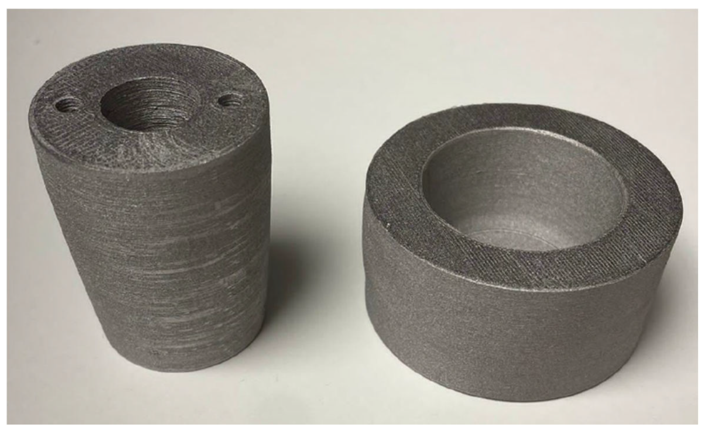
The machining was carried out on an OPTIturn S 750 CNC lathe (Optimum Maschinen Germany GmbH, Hallstadt, Germany) using lubricated turning operations with a maximum cutting speed of 200 m/min and a cut depth of 0.25 mm. The final machined inserts are shown in
Figure 5. The figure includes two images that allow the visualization of the opposite faces of both pieces. During machining, the inserts exhibited no structural defects such as cracks, delamination, or edge failures, confirming their mechanical integrity after sintering. As a quality control step, key insert dimensions were measured prior to machining and compared to their theoretical values, as shown in
Table 3. This ensured that sufficient material had been retained to reach the final dimensions and validated the effectiveness of the manufacturer’s scaling recommendations.
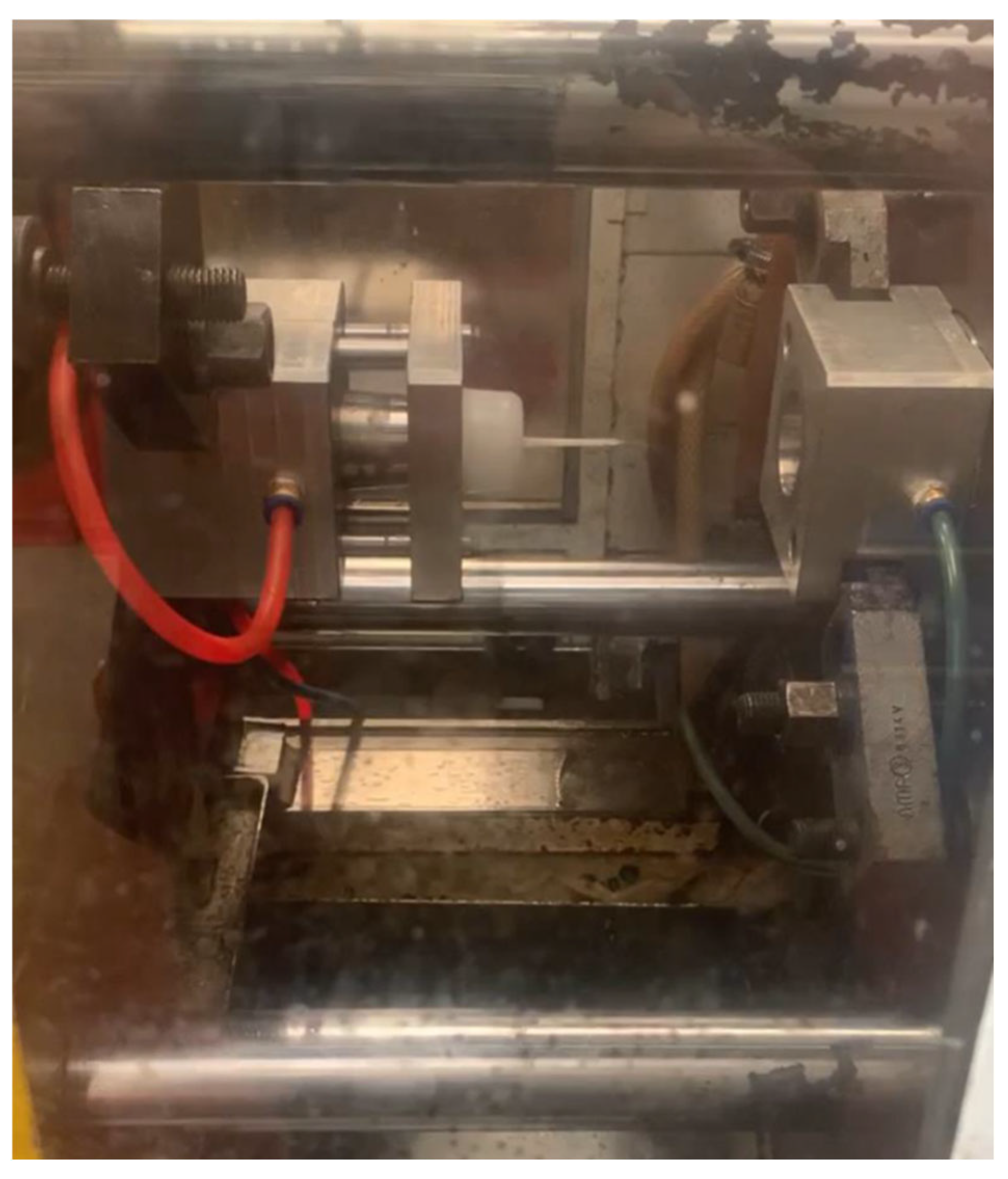
Finally, the inserts were completed with functional features, including threaded holes for mounting onto the mold base and an injection nozzle opening in the exterior insert, ensuring full compatibility with the molding system, and can be seen installed in the mold in their final configuration in
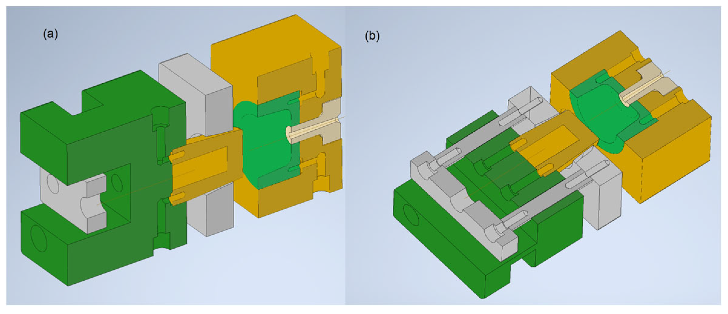
Figure 6. In addition,
Figure 7 presents the ideal representation of the complete mold assembly, with sectional views taken along the plane of the cooling channels and the plane corresponding to the insert mounting holes.
3. Results and Discussion
To evaluate the effectiveness of CCCs compared to traditional cooling methods, a machined replica of the inserts was created using 17-4 PH stainless steel from Outokumpu (Helsinki, Finland), matching the material used for the AM inserts. This ensured a fair comparison by maintaining an identical thermal conductivity coefficient, although a slight reduction in conductivity was expected in the AM inserts due to their inherent porosity.
For the machined inserts, conventional cooling was applied where possible. The interior insert, being solid, was fitted with a central drilled channel measuring 10 mm in diameter and 30 mm in depth, containing a welded plate 2 mm thick, and creating a bifurcated flow path for coolant circulation, as shown in
Figure 8. However, the exterior insert could not accommodate conventional cooling due to its geometry and instead relied on passive cooling from the mold base’s circulating water.
Polypropylene pellets (PP copolymer) were used for the injection molding trials. The process parameters included a clamping force of 25 tons, an injection pressure of 174 bar for the 6.7 s required to fill the injection chamber, and a holding pressure of 100 bar during cooling. The cooling time was varied during testing to determine the optimal value for each configuration.
To assess thermal behavior, repeated injections were performed in automatic mode until the system reached a steady-state operating temperature. Identical injection parameters were used for both insert sets: 6.7 s for injection followed by 25 s for cooling. After ejection, the mold was left open, and thermal imaging with a Testo 875-2i thermal camera (Testo SE & Co. KGaA, Titisee-Neustadt, Germany) was used to record the maximum surface temperature of the inserts at 5 s intervals, capturing the cooling rate for each configuration. This information is shown in
Figure 9.
Additionally, further injection tests were conducted at progressively shorter cooling times to determine the minimum feasible cycle time before part quality deteriorated. While no major defects such as incomplete filling were observed, surface imperfections became increasingly apparent as the cooling time decreased, caused by continued part contraction in open air after ejection.
Results indicated that CCC-based cooling was significantly more effective than traditional cooling, maintaining a much lower mold surface temperature. Under steady-state conditions, the CCC-cooled mold reached an initial surface temperature less than half that of the conventionally cooled mold. However, the slightly slower cooling rate observed in CCCs could be attributed to lower thermal gradients between the coolant and the part, as well as the expected reduction in thermal conductivity due to AM-induced porosity. Ultimately, the practical speed advantage of the AM mold depends on the required surface finish and geometric tolerances.
Figure 10 presents parts produced with cooling times of 5, 10, 15, and 20 s, along with a direct comparison between traditional cooling and CCC cooling at 20 s. We acknowledge that three-dimensional quality aspects—such as surface finish, absence of indentations, and concentricity—are difficult to convey in photographs; therefore, a scan and mesh comparison was carried out.
Quality experts from the company responsible for the injection molding concluded that parts cooled for 15 s with CCCs would be acceptable for low-demand applications, while those cooled for 20 s would meet standard quality requirements. A direct comparison between a 20 s CCC-cooled part and a traditionally cooled part clearly illustrates the benefit of conformal cooling: the conventionally cooled part exhibited significant ovality, whereas the CCC-cooled part maintained dimensional accuracy. Notably, the same quality achieved with CCCs in 20 s required 45 s with traditional cooling, highlighting the efficiency gains enabled by AM-produced cooling channels.
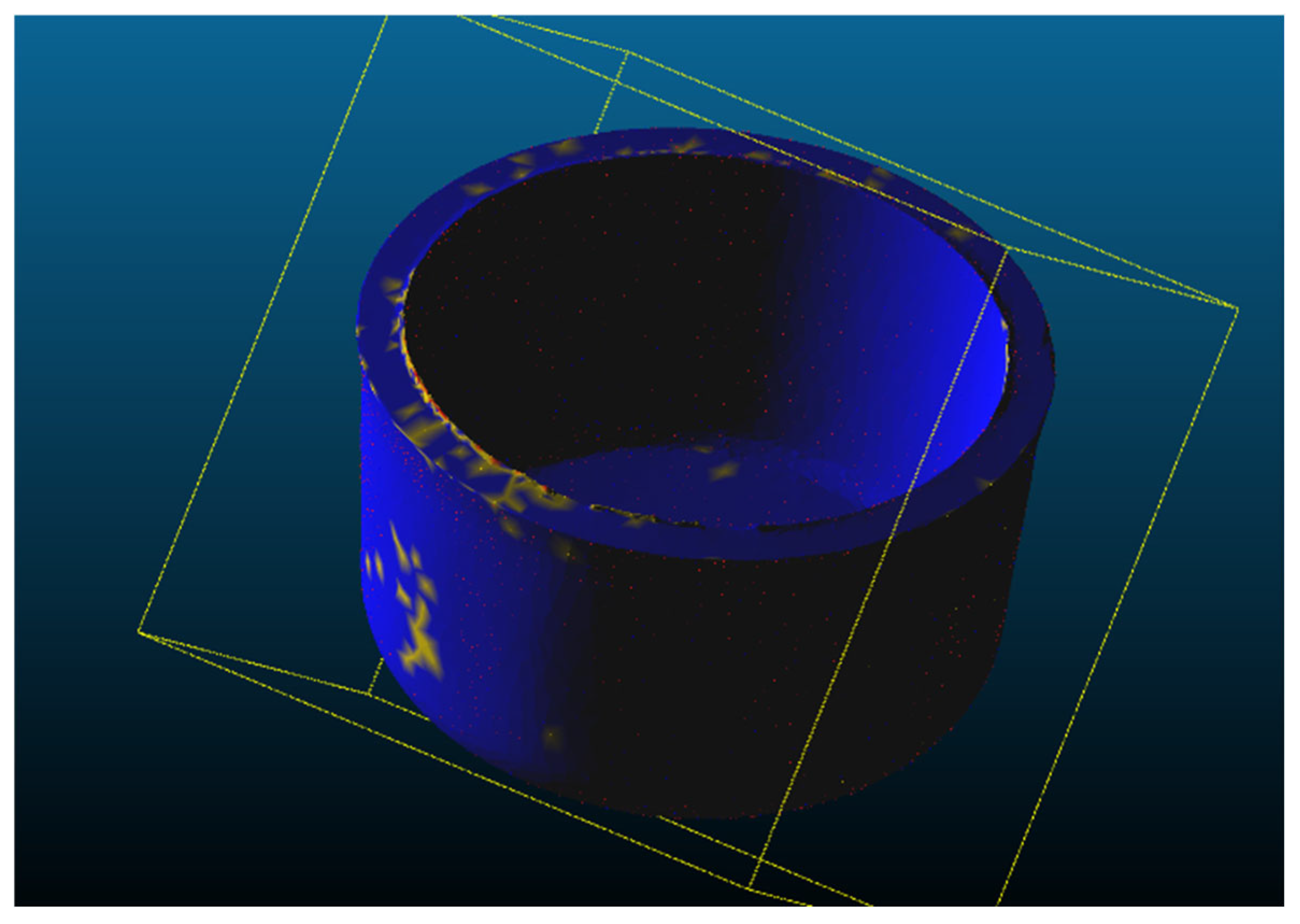
To verify this statement, two parts were digitally scanned: one produced with conventional cooling and a cooling time of 45 s, and another with enhanced cooling channels and a cooling time of 20 s. The resulting geometries were examined metrologically using a COMET L3D structured-light 3D scanner (Carl Zeiss Optotechnik GmbH, Neubeuern, Germany), along with the inspection software CloudCompare v2.13.1, which compares distances between mesh vertices (
Figure 11). In this figure, the superposition of both meshes can be seen, with discrepancies highlighted in yellow or red depending on their severity.
The analysis revealed a mean distance between vertices of 0.0167 mm, indicating excellent overlap between the geometries and validating the hypothesis that they are equivalent in quality. The complete distribution of distances can be found in
Figure 12, showing 8 classes or intervals that are differentiated with colors.
It is important to note that, after determining the optimal cooling time, a preliminary durability assessment of the mold was carried out by operating it continuously for an entire work shift of 8 h. Given the injection cycle time of the part, this produced 950 mass-produced units.
This result is significant because, although injection molds traditionally withstand hundreds of thousands of cycles, Metal-FFF inserts—produced by printing and subsequent sintering—are still not well characterized in terms of fatigue performance. Achieving this production volume therefore represents a meaningful step toward demonstrating the industrial viability of these components. Furthermore, no defects such as cracking or deformation of the insert surfaces were observed at the end of the process, nor were there any underfilling issues or signs of coolant leakage into the injection chamber caused by pores connecting the cooling circuit to the mold surface.
4. Conclusions
As a summary,
Table 4 shows the times for each part of the injection cycle for acceptable part quality. With a total cycle time of 65.7 s for traditional cooling and a time of 40.7 s for CCC cooling, we were able to reduce the total cycle time by 38%.
Figure 13 shows the ejection of a finished part after opening the mold.
We can therefore conclude that this study successfully demonstrates the feasibility and effectiveness of using additively manufactured tooling in high-performance industrial applications such as plastic injection molding.
This was achieved using Metal-FFF, a more accessible, user-friendly, and cost-effective AM technology compared to other metal AM methods such as LPBF. As a proof of concept, in addition to proving feasibility, this study achieved a significant improvement in process productivity, enabled by the integration of CCCs through AM. These results establish a working baseline for Metal-FFF CCCs and motivate focused process and design improvements to optimize cost, performance, and reliability.
During the tests conducted in this study, the mold operated continuously for eight hours without exhibiting fatigue or functional issues. However, further investigation is required to evaluate its long-term durability, which is a critical factor for ensuring the economic viability of injection-molded parts. Future work should include endurance testing under representative thermomechanical cycles (cooling/heating transients, clamping forces, injection pressures) to quantify degradation mechanisms over time. In particular, the fatigue life of sintered components should be characterized via standardized methodologies and correlated with in-press loading spectra to support durability predictions.
One of the main challenges for the practical application of this process is the inherent porosity of Metal-FFF components. If pores form between the cooling channels and the functional mold surfaces, coolant leakage into the injection cavity could render the mold unusable. Theoretically, porosity can be controlled by fine-tuning debinding and sintering parameters; however, in this study, process adjustments were not possible due to reliance on an external service provider that did not allow modifications. Additionally, determining the practical limit for the distance between cooling channels and the mold surface is essential. Even if some porosity is present, an optimized channel placement strategy could prevent leakage, improving the reliability of Metal-FFF molds for industrial use.
