Abstract
The design of the buckling configuration for a rolling soft robot has a significant effect on its rolling performance, but a thorough analysis remains lacking for many soft robot buckling configurations because of the difficulty of analyzing the buckling problem. This work comprehensively analyzes the static buckling morphology of two nested elastic rings under gravity based on a theoretical model using the minimum potential energy principle. Two nested rings present a tank-track-like buckling morphology under gravity, which depends on the length ratio, the bending stiffness ratio, and the gravity ratio of the inner ring to the outer ring. Increases in these three ratios lead to a lower tank-track-like buckling structure with an increased ground contact length and a reduced gravity moment on the slope. The tank-track-like buckling structures predicted using the theory agree well with Finite Element Method (FEM) simulations and experimental results. This work provides design guidance on achieving the maximum slope stability and the required robot configuration by tuning the geometrical and material parameters of rolling soft robots.
1. Introduction
Soft robots have gained massive attention owing to their excellent flexibility enabled by soft materials, intrinsically safe human–robot interactions, and good adaptability to harsh environments [1,2,3,4,5,6,7]. A variety of soft robots (soft wearable devices [8,9,10,11,12,13], soft grippers [14,15,16,17,18,19], soft arms [20,21,22,23,24,25], and mobile soft robots [26,27,28,29,30,31]) with different functions (i.e., transportation [2,5], manipulation [14,20], rehabilitation [32,33,34]) have been reported for distinct applications, such as healthcare [8], land exploration [2,5], industrial manufacturing [14,20], etc. Among mobile soft robots, rolling soft robots exhibit a good locomotion performance (velocity, stability, efficiency, and terrain adaptability) compared to that under other terrestrial locomotion modes for soft robots [5].
The configuration of a rolling soft robot has a significant effect on its rolling performance [35]. The common configurations adopted for rolling soft robots include circular shapes [36], polygonal shapes [37], ellipse-like shapes [38], and tank-track-like shapes [39]. Generally, rolling soft robots with a circular configuration possess a good rolling velocity, but their adaptability to complex terrains (the slope, the wide broken bridge and the stairs) is limited due to their relatively higher center of gravity and shorter ground contact lengths. Rolling soft robots with non-circular configurations (a polygonal shape [37], an ellipse-like shape [38], or a tank-track-like shape [39]) have a relatively lower center of gravity, longer ground contact lengths, and better adaptability to complex terrains, but their rolling velocities are usually slow due to their rolling mechanism being driven by large deformations.
Compared with previous rolling soft robots from other researchers, our previous work [5,40] reported a tank-track-like rolling soft robot with a balanced rolling performance (both a good rolling velocity and excellent terrain adaptability), where two nested elastic rings were used as the main structure of the robot and local snap-through buckling was employed for rolling locomotion actuation. The robot’s tank-track-like configuration provides good adaptability to complex terrains, and serves as the basis of the configuration for the rolling mechanism, which is driven by the local snap-through buckling. However, the previous theory [5,40] lacks a thorough analysis of the effect of the design parameters (length ratio, bending stiffness ratio, and gravity ratio) on the robot’s tank-track-like configuration and slope stability, which limits further improvements in this robot’s rolling performance. Thus, it is necessary to comprehensively analyze how the design parameters of the two nested elastic rings influence the robot configuration so that design guidance on the selection of the geometrical and material parameters can be obtained. The design parameters for the static configuration of the rolling soft robot comprise ratios of the length, bending stiffness, and gravity of the inner ring to those of the outer ring, which will be introduced in Section 3.1.
This study comprehensively analyzes the evolution of the static buckling morphology of two nested elastic rings under gravity based on a theoretical model using the minimum potential energy principle. This model is thoroughly validated using FEM simulations and experiments. The influences of the design parameters on the buckling morphology and the corresponding characteristic parameters (the ground contact length, the robot height, and the blister height) are uncovered. Equally, the adaptability of different buckling morphologies to slopes is analyzed by calculating their gravitational moments on slopes with distinct slope angles. This paper is organized as follows: The analytical model, simulation, and experimental methods are presented in Section 2. Section 3 provides a comprehensive analysis of how the gravity ratio, stiffness ratio, and length ratio of the inner ring to the outer ring influence the nested ring bucking configurations, as well as the resulting gravitational moments on slopes with varying inclination angles. Finally, Section 4 summarizes this study’s findings.
2. Materials and Methods
2.1. The Analytical Model
Two initially straight, nonstretchable beams with lengths Lₒ and Lᵢ (Lₒ < Lᵢ), thicknesses tₒ and tᵢ, and equal widths (wo = wi) are connected at their ends to form two rings with the radii Ro and Ri (Ro < Ri), respectively (see Figure 1a). According to the principle of the minimum potential energy [41,42], when two elastic rings with different radii are nested together on the ground, the circumferential mismatch between the two rings along with gravity induces a compressive force in the inner ring and a tensile force in the outer ring. Then, the tank-track-like buckling structure of the two nested rings is spontaneously formed, and a “blister” structure [43,44,45,46] in the inner ring is generated to minimize the overall potential energy, which is the balanced result between the strain energy and the gravitational potential energy.
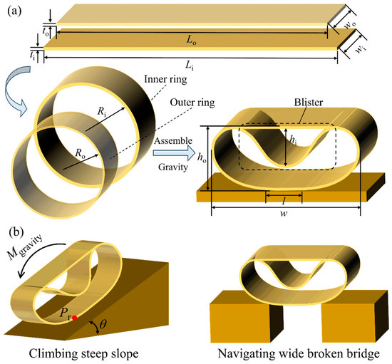
Figure 1.
(a) A schematic illustration of the formation and geometrical parameters of two nested elastic rings. Two rings with different diameters are nested together to form a tank-track-like structure under gravity. (b) The terrain adaptability to a steep slope and a wide broken bridge for rolling soft robots with a tank-track-like configuration.
The tank-track-like buckling structure is characterized by four geometrical parameters: total height (ho), total width (w), blister height (hi), and ground contact length (l). This study employs three dimensionless geometrical parameters to quantitatively characterize the morphology of the nested ring buckling structure: the aspect ratio α, the blister height, β and the contact length γ:
The dimensionless geometrical parameters α and γ are related to the outline of the buckling structure, i.e., the tank-track-like configuration, which can influence the terrain adaptability of the rolling soft robot (Figure 1b). The dimensionless geometrical parameter β is related to the rolling velocity of the rolling soft robot [5]. Thus, these three dimensionless geometrical parameters determine the rolling performance of the rolling soft robot, and then, their relationship with the design parameters is analyzed using a theoretical model based on the minimum potential energy principle.
Both Cartesian and natural coordinate systems are adopted to analyze the structural evolution of the nested ring buckling structure under gravity (Figure 2). The Cartesian coordinate system oxy is established by setting the midpoint of the contact surface between the nested ring buckling structure and the ground as the origin. In the following text, the subscripts ‘c’, ‘i’, and ‘o’ denote the combined segment of two rings, the inner ring, and the outer ring, respectively. The natural coordinates sc, si, and so are used to denote the arc length of the combined segment of two rings, the arc length of the inner ring, and the arc length of the outer ring, respectively. The origin in natural coordinates of the combined segment of two rings (sc = 0) is defined at the separation point where the nested ring buckling structure detaches from the ground surface. The bottom of the inner ring’s blister is set as the origin of natural coordinates of the inner ring (si = 0), while the vertex of the outer ring is set as the origin of the outer ring (so = 0). The inner (outer) ring detachment region can be expressed as . For the nested ring buckling structure, φξ(sξ) (ξ = c, i, o) denotes the angle between the tangent line at the given point qξ (ξ = c, i, o) and the positive direction of the x axis.
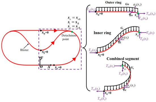
Figure 2.
A force diagram of the nested ring buckling structure.
It is assumed that the mass distribution is uniform along the direction of the arc length for two rings, and the nested ring buckling structure is symmetric. For simplification, only the right half of the nested ring buckling structure is considered due to symmetry (Figure 2). The position of an arbitrary point qξ (ξ = c, i, o) on the nested ring buckling structure can be described in Cartesian coordinates as . The inextensible condition [47,48] for the inner and outer rings requires the ring curve to satisfy , where denotes the unit tangent vector of the curve. Thus, the following equation can be obtained.
This study quantitatively investigates the morphological changes in the two nested elastic rings under gravity through energy minimization principles. The energy functional of the system includes the bending energy, characterizing bending deformation; gravitational potential energy, describing the effect of gravity; and constraints in the x and y directions arising from the inextensible condition. The energy functional can be expressed as follows:
where Kξ = EξIξ (ξ = c, i, o) denotes the bending stiffness of the ring, which is the product of the modulus of elasticity Eξ and the moment of inertia of the cross-section Iξ. . denotes the curvature. σξ (ξ = c, i, o) denotes the mass per unit length of the ring, and . Gξ(ξ = c, i, o) = σξLξ denotes the gravity of the ring. Tξx and Tξy (Lagrange multipliers) denote the internal forces in the x and y directions, respectively.
The first variation in the energy functional E is derived by considering infinitesimal virtual displacements of the nested ring buckling configuration.
where is a small positive parameter. Given the arbitrary characteristics of these parameters , , and , the equilibrium equations for the right half of the nested ring buckling structure can be derived as follows:
Equation (5) states that the internal forces in the x direction of the nested ring buckling structure remain constant, whereas the internal forces in the y direction vary with the arc length. Note that in the energy functional of Equation (3), Tξx and Tξy are initially the Lagrange multipliers of two constraint terms. After the first variation in the energy functional, Tξx and Tξy show the meaning of the internal constraint forces in the equilibrium equation (Equation (5)). At the detachment point (the green square in Figure 2), the internal force of the nested ring buckling structure satisfies the following equilibrium equation:
Adding appropriate boundary and continuity conditions allows Equation (5) to be solved numerically using the bvp4c solver on the MATLAB 2020b platform [49,50,51], and thus, the deformation law for the nested ring buckling structure under gravity is revealed. The boundary conditions for the surface contact (l > 0) are as follows:
For line contact (l = 0), the following boundary conditions are applied:
Furthermore, the nested ring buckling configuration should satisfy the continuity conditions at the detachment point (denoted by the green square in Figure 2):
2.2. The Experimental Method
The outer ring was made of 0.1 mm thick printing paper with a width of 45 mm, exhibiting a density of 750 kg·m−3 and a Young’s modulus of 1.65 GPa. The inner ring was made of 45 mm wide PET strips (0.3 mm thick) coated with a 0.12 mm silicone layer to enhance the gravitational effects. The PET/silicone composites exhibit an effective density of 2800 kg·m−3 and an effective Young’s modulus of 2.4 GPa. The two rings were bonded at both ends using double-sided tape to form closed loops, respectively. The bonding section was placed at the bottom of the nested ring buckling structure to avoid it influencing the overall structure. In the experiments, the inner ring’s circumference was fixed at 380 mm, and Li/Lo was regulated by adjusting the outer ring’s circumference to study how the static structure evolved under gravity.
2.3. The Simulation Method
The theoretical analysis was further validated through FEM simulations conducted using the implicit method in the commercial software ABAQUS 2021 [52,53,54]. The simulation model used the same material properties and geometrical parameters as those in the theoretical model so that it could be compared with theory. Solid models of the two rings were constructed based on the theoretical dimensions of the outer ring, and the inner ring’s circumference was precisely controlled via thermal expansion to match its theoretical dimensions. The simulation setup included a fixed rigid ground surface in contact with the bottom of the model and uniform gravitational loading throughout the nested ring buckling structure. All simulations employed C3D8R elements, and mesh sensitivity studies were performed to verify both the accuracy of the results and mesh fineness.
3. Results and Discussions
3.1. Evolution of the Configuration of Two Nested Rings
When subjected to gravitational loading, two nested rings resting horizontally on the ground undergo significant morphological transformation. The equilibrium configuration of the nested ring buckling configuration is principally governed by the rings’ bending stiffness, circumferential length, and gravity. Based on this understanding, the static configurations of the two nested rings can be effectively controlled by tuning three dimensionless design parameters: the ratios of the stiffness (Ki/Ko), length (Li/Lo), and gravitational force (Gi/Go) of the inner ring to those of the outer ring.
The evolution of the buckling configuration of the two nested rings is systematically analyzed for different combinations of the Ki/Ko and Li/Lo parameters, with Gi/Go fixed, as shown in Figure 3a. The aspect ratio α and the ground contact length γ of the configuration are predominantly governed by Ki/Ko, whereas Li/Lo primarily modulates the height β of the inner ring’s blister in the nested ring buckling structure. When Li/Lo is fixed and Ki/Ko increases, the outer contour of the nested ring buckling structure changes progressively from a circular shape to a tank-track-like shape. This morphological shift is characterized by widening of the structure, a reduction in height, and elongation of the ground contact distance. The tank-track-like configuration enhances the adaptability of rolling soft robots when moving across complex terrains [5]. When Ki/Ko remains constant, the blister height β exhibits a positive correlation with Li/Lo, while the combined segment of two rings progressively decreases. Notably, the critical state where the blister reaches its maximum height occurs when the bottom of the blister (si = 0) is in contact with the combined segment of two rings. This unique configuration is synergistically determined by Ki/Ko and Li/Lo.
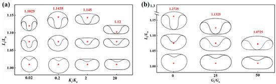
Figure 3.
Evolution of the configurations of the nested ring buckling structures. (a) Nested ring buckling structures with different Ki/Ko and Li/Lo values. Gi/Go is fixed at 18. (b) Nested ring buckling structures with different Gi/Go and Li/Lo values. Ki/Ko is fixed at 1. The red dots show the Li/Lo values of corresponding configurations.
Figure 3b illustrates the evolution of the configuration with different Gi/Go and Li/Lo parameters when Ki/Ko is fixed. The influence of Gi/Go on the nested ring buckling configuration resembles that of Ki/Ko, while Gi/Go has a negligible impact on the curved feature of the outer contour’s top. Equally, Gi/Go has a larger impact on the ground contact length and the blister height compared with that of Ki/Ko. With an increase in the inner ring’s gravity, the blister height increases due to its larger weight, and the ground contact length rises since a larger area of contact with the ground is required to support the heavier structure. The curved feature of the structure’s top is not influenced since Gi/Go has a negligible effect on the tensile force in the outer ring.
The above analysis reveals that the static configuration of the nested ring buckling structure under gravity is collectively governed by Gi/Go, Ki/Ko, and Li/Lo, which characterize the geometrical and material properties of the structure. Gi/Go and Ki/Ko predominantly dictate the macroscopic geometry of the nested ring buckling structure (e.g., the aspect ratio α and the ground contact length γ), while Li/Lo plays a role in shaping the local features, such as the blister height β and the combined segment length of both rings. This finding provides a critical theoretical basis for the morphological design of flexible nested ring buckling structures.
3.2. The Influence of the Design Parameters on α and β
To further reveal the effect of specific design parameters on certain geometrical parameters of the nested ring buckling structure, systematical analyses using the theory and FEM simulations are conducted. When Li/Lo and Gi/Go remain constant, an increase in Ki/Ko significantly transforms the nested ring buckling structure from a circular shape to a tank-track-like shape. This morphological evolution is reflected by the positive correlation between the characteristic parameter α and Ki/Ko, as illustrated in Figure 4a. Notably, α exhibits strong dependence on Ki/Ko but weak sensitivity to Li/Lo, which aligns with the results in Figure 3a.
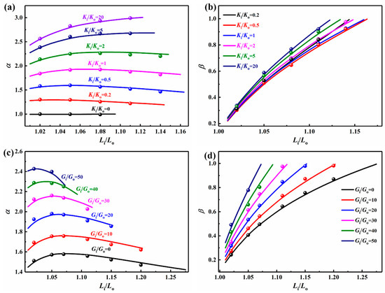
Figure 4.
Ki/Ko and Li/Lo versus (a) α and (b) β calculated using the theory and FEM simulation for Gi/Go = 18. Gi/Go and Li/Lo versus (c) α and (d) β calculated using the theory and FEM simulation for Ki/Ko = 1. The solid lines denote the theoretical results, and the circles denote the FEM simulation results.
When Ki/Ko is kept constant, increasing the length of the inner ring Li substantially elevates the structure’s compressive strain energy. This energy accumulation can be mitigated effectively by enhancing the blister height (see Figure 4b), which serves as an energy release mechanism to minimize the structure’s total energy. When Gi/Go is constant, the effect of Ki/Ko on β is small, which is consistent with the results in Figure 3a.
For a fixed Li/Lo value with Ki/Ko = 1, the parameter α is directly dependent on Gi/Go. As evidenced in Figure 4c, α increases monotonically with Gi/Go. However, when Gi/Go is held constant, the effect of Li/Lo on α is small. Furthermore, β increases nonlinearly with Li/Lo at a constant Gi/Go, as demonstrated in Figure 4d. When Li/Lo is constant, the enhanced gravity of the inner ring Gi increases the structure’s gravitational potential energy. The inner ring compensates for this by increasing the blister height to restore equilibrium, resulting in a continuous increase in β with higher Gi/Go values. Note that the cases of Gi/Go = 0 and Gi/Go = 50 are the lower and upper theoretical limitations for isolating the influence of the inner ring’s gravity and exploring extreme forms of buckling. In the experiment, a large Gi/Go value can be achieved by using a thick silicone layer for the inner ring.
The above analysis reveals that the characteristic parameters α and β of the nested ring buckling structure exhibit significant multi-parameter coupling behavior. Their variation patterns are governed by the combined effects of three dimensionless parameters: Ki/Ko, Gi/Go, and Li/Lo. As evidenced in Figure 4, the theoretical predictions show excellent agreement with the results of the FEM simulations, thus validating the accuracy and reliability of the proposed theoretical model for predicting the structural behavior of the nested ring buckling structure.
3.3. The Influence of the Design Parameters on γ
The normalized ground contact length γ of the nested ring buckling structure depends strongly on Ki/Ko and Gi/Go while demonstrating relatively weak sensitivity to Li/Lo (Figure 5). Increasing Ki/Ko enhances the inner ring’s relative rigidity, thereby preserving contact with the ground. Conversely, the configuration shows line contact (γ = 0) with the ground when Ki/Ko is small (see Figure 5a). Gi/Go modulates the contact characteristics by governing the system’s total gravitational potential. An increased Gi/Go value enhances the contact with the ground through larger gravity, as shown in Figure 5b. Significantly, Ki/Ko exhibits synergistic interactions with Gi/Go, where simultaneous increases in these two parameters produce an amplified effect on γ.
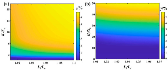
Figure 5.
(a) Ki/Ko and Li/Lo versus γ for Gi/Go = 18. (b) Gi/Go and Li/Lo versus γ for Ki/Ko = 1.
3.4. The Experimental and FEM Verification
To validate the accuracy and reliability of the theoretical model, we conducted experimental tests of static configurations of the two nested rings under gravity by varying the Li/Lo ratios (see Figure 6), where a camera in front of the rings was used to obtain the buckling configurations of the rings. In the experiments, the circumference of the inner ring was kept constant at 380 mm, and the densities of the inner and outer rings were kept constant. Adjusting the circumference of the outer ring (printing paper) changes both the Li/Lo and Gi/Go values. Then, the theoretical results with the corresponding parameters are calculated and overlapped onto the experimental buckling configuration, as shown in Figure 6. Characteristic parameters (α, β) of the buckling structures are compared between the theory and the experiment, as shown in Table 1, where γ = 0 for all of the rings. The results demonstrate excellent agreement between the theory and the experiment for the static configurations under gravity, thus validating the accuracy and predictive capability of the proposed theoretical model.
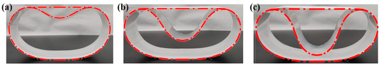
Figure 6.
A comparison between the theory and experiment for Li/Lo and Gi/Go values of (a) 1.01 and 3.77, (b) 1.09 and 4.07, and (c) 1.15 and 4.29 at Ki/Ko = 1.45. The red dashed–dotted lines denote the theoretical results.

Table 1.
Configuration comparison between theory and experiment.
Furthermore, we compared the FEM simulation and the theory by varying one parameter (Li/Lo, Gi/Go, or Ki/Ko) while fixing the other two, as shown in Figure 7. Both the FEM simulation and theory show strong consistency in predicting the static buckling configuration of the two nested rings under different parameters, thereby confirming the model’s accuracy. Based on this result, precise regulation of the static configurations of the nested ring buckling structure can be achieved by reasonably selecting the design parameters (Li/Lo, Gi/Go, or Ki/Ko). This will satisfy specific structural morphology needs in different application scenarios for rolling soft robots. Note that the cases Gi/Go = 0 and Gi/Go = 50 are the lower and upper theoretical limitations for isolating the influence of the inner ring’s gravity and exploring extreme forms of buckling.
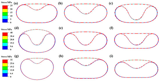
Figure 7.
Comparison between theory and FEM simulation for Li/Lo of (a) 1.02, (b) 1.05, and (c) 1.11 with Gi/Go = 18 and Ki/Ko = 2. Comparison between theory and FEM simulation for Ki/Ko of (d) 0.5, (e) 2, and (f) 20 with Li/Lo = 1.08 and Gi/Go = 18. Comparison between theory and FEM simulation for Gi/Go of (g) 0, (h) 30, and (i) 50 with Li/Lo = 1.02 and Ki/Ko = 1. The red dashed line presents the theoretical results.
3.5. The Influence of the Design Parameters on the Gravitational Moment
To evaluate the slope adaptability of a rolling soft robot with the nested ring buckling structure, we quantitatively assessed the gravitational moment Mgarvity relative to point Pc (the lower endpoint of the ground contact length) at various inclination angles (see Figure 1b). Point Pc serves as the reference point for Mgarvity calculation, representing the instantaneous center of rotation when the robot cannot remain stationary on a slope, i.e., the structure undergoes rigid-body rotation around point Pc due to the gravitational moment. The gravitational moment calculations are based on the horizontal configuration of the nested ring buckling structure, which is reliable for small slopes (θ < 20°) because the gravity component perpendicular to the slope is dominant.
Increasing the structural parameters Gi/Go and Ki/Ko progressively reduces Mgarvity of the nested ring buckling structure, as presented in Figure 8a,b. Interestingly, Mgarvity approaches zero and eventually becomes negative on the slopes, indicating that the structure can remain stable on such terrain. Figure 8c,d show the maximum stable inclination angles θmax (Mgarvity = 0) for the different design parameters Gi/Go, Ki/Ko, and Li/Lo, which reveal distinct stability thresholds for various configurations. The maximum critical slope inclination in this study is 20° because soft rolling robots can only climb slopes with an angle of less than 20° [5]. The parametric analysis reveals that increasing the values of Gi/Go, Ki/Ko, and Li/Lo enhances both the ground contact length and the overall structural width, consequently significantly elevating θmax. The improved stability stems from the increased resistance to Mgarvity of the flattened nested ring buckling configuration, suggesting that strategic design parameter selection can avoid spontaneous downward rolling and reduce the drive force required to traverse the inclined terrain.
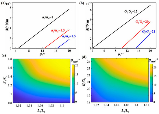
Figure 8.
Mgarvity of the nested ring buckling structure at different slope angles for different (a) Ki/Ko and (b) Gi/Go values. (c) Ki/Ko and Li/Lo versus θmax for Gi/Go = 18. (d) Gi/Go and Li/Lo versus θmax for Ki/Ko = 1.
4. Conclusions
This study presents a theoretical model for a nested ring buckling structure based on the minimum potential energy principle, which elucidates the evolution mechanism for the configuration under gravity and the corresponding control strategy. Theoretical analyses demonstrate that the morphological parameters (α, β, and γ) are governed cooperatively by three design parameters (Ki/Ko, Gi/Go, and Li/Lo). Ki/Ko and Gi/Go govern the macroscopic morphological evolution of the nested ring buckling structure from the circular shape to the tank-track-like shape. Conversely, Li/Lo primarily modulates the local features and exhibits a strong correlation with the blister height and the combined segment length of both rings. Notably, the synergistic effect between these three parameters increases the ground contact length and significantly improves the static stability on inclined planes. Furthermore, the experiment and FEM simulations confirm that the theoretical model can accurately predict stable configurations of the nested ring buckling structure. When the nested ring buckling structure is used in a rolling soft robot [5], the overall configuration of the robot (the parameters α and γ) determines its terrain adaptability (Section 3.5 gives an example of slope adaptability), and the blister configuration (parameter β) is related to the critical loading of actuation (see Figure 6 of ref. [5] for details). Thus, by tuning three design parameters (Ki/Ko, Gi/Go, and Li/Lo) of the two nested rings, the robot’s terrain adaptability and critical loading can be tuned. This work not only advances our fundamental understanding of the deformation of flexible nested ring buckling structures under gravity but also establishes a robust design methodology for optimizing the design of nested ring buckling structures for engineering applications.
Author Contributions
Conceptualization: P.Y.; methodology: F.D.; software: F.D.; validation: F.D. and K.P.; investigation: F.D. and D.Y.; writing—original draft preparation: F.D.; writing—review and editing: P.Y. and F.D.; visualization: K.P. and D.Y.; supervision: P.Y.; project administration: P.Y. and F.D.; funding acquisition: P.Y. and F.D. All authors have read and agreed to the published version of the manuscript.
Funding
This research was funded by the National Natural Science Foundation of China, grant number 12302132, the Natural Science Foundation of Fujian Province, grant number 2023J05249 and the Research Project of Fashu Foundation, grant number MFK24012.
Data Availability Statement
The data that support the findings of this study are available from the corresponding author, P.Y., upon reasonable request.
Acknowledgments
The authors would like to thank Fuzhou University and Minjiang University for their support.
Conflicts of Interest
The authors declare no conflicts of interest.
References
- Yan, Y.; Wang, T.; Zhang, R.; Liu, Y.; Hu, W.; Sitti, M. Magnetically assisted soft milli-tools for occluded lumen morphology detection. Sci. Adv. 2023, 9, eadi3979. [Google Scholar] [CrossRef]
- Yang, P.; Wang, X.; Dang, F.; Yang, Z.; Liu, Z.; Yan, Y.; Zhu, L.; Liu, Y.; Xiao, H.; Chen, X. Elementary Slender Soft Robots Inspired by Skeleton Joint System of Animals. Soft Robot. 2019, 6, 377–388. [Google Scholar] [CrossRef] [PubMed]
- Yan, Y.; Shui, L.; Liu, S.; Liu, Z.; Liu, Y. Terrain Adaptability and Optimum Contact Stiffness of Vibro-bot with Arrayed Soft Legs. Soft Robot. 2022, 9, 981–990. [Google Scholar] [CrossRef] [PubMed]
- Garcia, M.; Esquen, A.-C.; Sabbagh, M.; Grace, D.; Schneider, E.; Ashuri, T.; Voicu, R.C.; Tekes, A.; Amiri Moghadam, A.A. Soft Robots: Computational Design, Fabrication, and Position Control of a Novel 3-DOF Soft Robot. Machines 2024, 12, 539. [Google Scholar] [CrossRef]
- Yang, P.; Mao, Y.; Liu, H.; Gao, L.; Huang, F.; Dang, F. A Rolling Soft Robot Driven by Local Snap-Through Buckling. Soft Robot. 2024. [Google Scholar] [CrossRef]
- Hasanshahi, B.; Cao, L.; Song, K.-Y.; Zhang, W. Design of Soft Robots: A Review of Methods and Future Opportunities for Research. Machines 2024, 12, 527. [Google Scholar] [CrossRef]
- Ridremont, T.; Singh, I.; Bruzek, B.; Erel, V.; Jamieson, A.; Gu, Y.; Merzouki, R.; Wijesundara, M.B.J. Soft Robotic Bilateral Rehabilitation System for Hand and Wrist Joints. Machines 2024, 12, 288. [Google Scholar] [CrossRef]
- Liu, H.; Wu, C.; Lin, S.; Xi, N.; Lou, V.W.Q.; Hu, Y.; Or, C.K.L.; Chen, Y. From Skin Movement to Wearable Robotics: The Case of Robotic Gloves. Soft Robot. 2024, 11, 755–766. [Google Scholar] [CrossRef]
- Xu, M.; Liao, J.; Li, J.; Shi, Y.; Zhang, Z.; Fu, Y.; Gu, Z.; Xu, H. Elastic Nanoparticle-Reinforced. Conductive Structural Color Hydrogel with Super Stretchability, Self-Adhesion, Self-Healing as Electrical/Optical Dual-Responsive Visual Electronic Skins. Exploration 2025, 5, 270008. [Google Scholar] [CrossRef]
- Sun, Z.; Ou, Q.; Dong, C.; Zhou, J.; Hu, H.; Li, C.; Huang, Z. Conducting polymer hydrogels based on supramolecular strategies for wearable sensors. Exploration 2024, 4, 20220167. [Google Scholar] [CrossRef]
- Ma, J.; Cheng, X.; Wang, P.; Jiao, Z.; Yu, Y.; Yu, M.; Luo, B.; Yang, W. A Haptic Feedback Actuator Suitable for the Soft Wearable Device. Appl. Sci. 2020, 10, 8827. [Google Scholar] [CrossRef]
- Simons, M.; Digumarti, K.; Le, N.; Chen, H.; Carreira, S.; Zaghloul, N. B: Ionic Glove: A soft smart wearable sensory feedback device for upper limb robotic prostheses. IEEE Robot. Autom. Let. 2021, 6, 3311–3316. [Google Scholar] [CrossRef]
- Fiska, V.; Mitsopoulos, K.; Mantiou, V.; Petronikolou, V.; Antoniou, P.; Tagaras, K.; Kasimis, K.; Nizamis, K.; Tsipouras, M.G.; Astaras, A. Integration and Validation of Soft Wearable Robotic Gloves for Sensorimotor Rehabilitation of Human Hand Function. Appl. Sci. 2025, 15, 5299. [Google Scholar] [CrossRef]
- Zhu, M.; Xie, M.; Mori, Y.; Dai, J.; Kawamura, S.; Yue, X. A Variable Stiffness Soft Gripper Based on Rotational Layer Jamming. Soft Robot. 2024, 11, 85–94. [Google Scholar] [CrossRef] [PubMed]
- Wang, H.; Yang, X.; Qu, H.; Wang, X.; Liu, W.; Hu, B.; Guo, S. Construction and analysis of a thick-panel origami gripper with soft joints based on square-twist origami tessellation. Thin-Walled Struct. 2025, 210, 113049. [Google Scholar] [CrossRef]
- Ding, W.; Zhou, Y.; Sun, M.; Fu, H.; Chen, Y.; Zhang, Z.; Pei, Z.; Chai, H. Magnetorheological elastomer actuated multi-stable gripper reinforced stiffness with twisted and coiled polymer. Thin-Walled Struct. 2023, 193, 111223. [Google Scholar] [CrossRef]
- Zhang, Y.; Wang, Z. Integrating a Soft Pneumatic Gripper in a Robotic System for High-Speed Stable Handling of Raw Oysters. Foods 2025, 14, 2875. [Google Scholar] [CrossRef]
- Shen, J.; Ramírez-Gómez, Á.; Wang, J.; Zhang, F.; Li, Y. Intelligent and Precise Textile Drop-Off: A New Strategy for Integrating Soft Fingers and Machine Vision Technology. Textiles 2025, 5, 34. [Google Scholar] [CrossRef]
- Chen, Q.; Dingena, S.; Jovana, J. Model-based design of variable stiffness soft gripper actuated by smart hydrogels. Soft Robot. 2024, 11, 924–934. [Google Scholar] [CrossRef]
- Gomez, V.; Hernando, M.; Aguado, E.; Bajo, D.; Rossi, C. Design and Kinematic Modeling of a Soft Continuum Telescopic Arm for the Self-Assembly Mechanism of a Modular Robot. Soft Robot. 2024, 11, 347–360. [Google Scholar] [CrossRef]
- Liu, S.; Jiao, J.; Kong, W.; Huang, H.; Mei, T.; Meng, F.; Ming, A. Modeling of a bio-inspired soft arm with semicircular cross section for underwater grasping. Smart Mater. Struct. 2021, 30, 125029. [Google Scholar] [CrossRef]
- Uppalapati, N.; Girish, K. VaLeNS: Design of a novel variable length nested soft arm. IEEE Robot. Autom. Let. 2020, 5, 1135–1142. [Google Scholar] [CrossRef]
- García-Samartín, J.F.; Rieker, A.; Barrientos, A. Design, Manufacturing, and Open-Loop Control of a Soft Pneumatic Arm. Actuators 2024, 13, 36. [Google Scholar] [CrossRef]
- Papadakis, E.; Tsakiris, D.P.; Sfakiotakis, M. An Octopus-Inspired Soft Pneumatic Robotic Arm. Biomimetics 2024, 9, 773. [Google Scholar] [CrossRef] [PubMed]
- Wu, Q.; Gu, Y.; Li, Y.; Zhang, B.; Chepinskiy, S.A.; Wang, J.; Zhilenkov, A.A.; Krasnov, A.Y.; Chernyi, S. Position Control of Cable-Driven Robotic Soft Arm Based on Deep Reinforcement Learning. Information 2020, 11, 310. [Google Scholar] [CrossRef]
- Liu, J.; Li, P.; Huang, Z.; Liu, H.; Huang, T. Earthworm-inspired multimodal pneumatic continuous soft robot enhanced by winding transmission. Cyborg Bionic Syst. 2025, 6, 0204. [Google Scholar] [CrossRef] [PubMed]
- Tongil Park Cha, Y. Soft mobile robot inspired by animal-like running motion. Sci. Rep. 2019, 9, 14700. [Google Scholar] [CrossRef]
- Al-Ibadi, M.A.; Al-Assfor, F.K.; Al-Ibadi, A. An Automatic Self Shape-Shifting Soft Mobile Robot (A4SMR). Robotics 2022, 11, 118. [Google Scholar] [CrossRef]
- Ye, C.; Liu, Z.; Yu, S.; Fan, Z.; Wang, Y. Design and Motion Analysis of a Soft-Limb Robot Inspired by Bacterial Flagella. Biomimetics 2023, 8, 271. [Google Scholar] [CrossRef]
- Pilz daCunha, M.; Ambergen, S.; Debije, M.G.; Homburg, E.F.G.A.; denToonder, J.M.J.; Schenning, A.P.H.J. A soft transporter robot fueled by light. Adv. Sci. 2020, 7, 1902842. [Google Scholar] [CrossRef] [PubMed]
- Lodh, T.; Le, H.P. An Ultra High Gain Converter for Driving HASEL Actuator Used in Soft Mobile Robots. Biomimetics 2023, 8, 53. [Google Scholar] [CrossRef]
- Bazina, T.; Kladarić, M.; Kamenar, E.; Gregov, G. Development of Rehabilitation Glove: Soft Robot Approach. Actuators 2024, 13, 472. [Google Scholar] [CrossRef]
- Ribas Neto, A.; Fajardo, J.; da Silva, W.H.A.; Gomes, M.K.; de Castro, M.C.F.; Fujiwara, E.; Rohmer, E. Design of Tendon-Actuated Robotic Glove Integrated with Optical Fiber Force Myography Sensor. Automation 2021, 2, 187–201. [Google Scholar] [CrossRef]
- Zhou, Z.; Ai, Q.; Li, M.; Meng, W.; Liu, Q.; Xie, S.Q. The Design and Adaptive Control of a Parallel Chambered Pneumatic Muscle-Driven Soft Hand Robot for Grasping Rehabilitation. Biomimetics 2024, 9, 706. [Google Scholar] [CrossRef] [PubMed]
- Dang, F.; Peng, K.; Yang, P.; Liu, Z.; Zheng, X. Morphology analysis of a thin elastic ring under gravity for configuration design of rolling soft robots. Meccanica 2025, 60, 1437–1444. [Google Scholar] [CrossRef]
- Li, W.B.; Zhang, W.M.; Gao, Q.H.; Guo, Q.; Wu, S.; Zou, H.X.; Peng, Z.K.; Meng, G. Electrically Activated Soft Robots: Speed Up by Rolling. Soft Robot. 2021, 8, 611–624. [Google Scholar] [CrossRef] [PubMed]
- Wang, J.; Fei, Y.; Liu, Z. Locomotion modeling of a triangular closed-chain soft rolling robot. Mechatronics 2019, 57, 150–163. [Google Scholar] [CrossRef]
- Firouzeh, A.; Ozmaeian, M.; Alasty, A.; Iraji zad, A. An IPMC-made deformable-ring-like robot. Smart Mater. Struct. 2012, 21, 065011. [Google Scholar] [CrossRef]
- Johnsen, L.P.; Tsukagoshi, H. Deformation-Driven Closed-Chain Soft Mobile Robot Aimed for Rolling and Climbing Locomotion. IEEE Robot. Autom. Lett. 2022, 7, 10264–10271. [Google Scholar] [CrossRef]
- Yang, P.; Huang, R.; Dang, F.; Shan, B.; Wang, D.; Liu, H.; Li, Y.; Liao, X. Motorizing the buckled blister for rotary actuation. Exploration 2024, 4, 20230055. [Google Scholar] [CrossRef]
- Yang, P.; Wang, D.; Liu, H.; Huang, R.; Li, X.; Xin, S.; Huang, F.; Dang, F. Spontaneous buckling morphology transition of an elastic ring confined in an annular region constraint. Eur. J. Mech. A—Solids 2023, 100, 105026. [Google Scholar] [CrossRef]
- Yang, P.; Xin, S.; Dang, F. A single-axis force sensor based on a 3D-printed elastic ring. Measurement 2024, 236, 115140. [Google Scholar] [CrossRef]
- De Tommasi, D.; Devillanova, G.; Maddalena, F.; Napoli, G.; Puglisi, G. Elastic multi-blisters induced by geometric constraints. Proc. R. Soc. A—Math. Phy. 2021, 477, 20200562. [Google Scholar]
- Yu, C.; Zhang, M. Evaluation Methods and Influence Factors of Blisters Disease in Concrete Composite Bridges. Buildings 2024, 14, 1763. [Google Scholar] [CrossRef]
- Pascalis, R.D.; Napoli, G.; Turzi, S. Growth-induced blisters in a circular tube. Phys. D 2014, 283, 1–9. [Google Scholar] [CrossRef]
- Napoli, G.; Turzi, S. The delamination of a growing elastic sheet with adhesion. Meccanica 2017, 52, 3481–3487. [Google Scholar] [CrossRef]
- Yang, P.; Li, X.; Xin, S.; Mao, Y.; Gao, L.; Dang, F. Snap-through mechanism of a thin beam confined in a curved constraint. Thin-Walled Struct. 2025, 207, 112745. [Google Scholar] [CrossRef]
- Yang, P.; Liu, H.; Li, X.; Xin, S.; Dang, F. Snap-through mechanism of an elastic bimetal ring for rotary actuation. Commun. Nonlinear Sci. 2025, 140, 108432. [Google Scholar] [CrossRef]
- Cutolo, A.; Fraldi, M.; Napoli, G.; Puglisi, G. Growth of a flexible fibre in a deformable ring. Soft Matter 2023, 19, 3366–3376. [Google Scholar] [CrossRef] [PubMed]
- Kumar, B.R.; Mohana, C.M. Thermal and entropy analysis of ternary hybrid nanofluid using Keller Box method. Commun. Nonlinear Sci. 2025, 140, 108366. [Google Scholar] [CrossRef]
- Noakes, L.; Zhang, E. Finding extremals of Lagrangian actions. Commun. Nonlinear Sci. 2023, 116, 106826. [Google Scholar] [CrossRef]
- Jimenez Abarca, M.; Darabi, R.; de Sa, J.C.; Parente, M.; Reis, A. Multi-scale modeling for prediction of residual stress and distortion in Ti–6Al–4V semi-circular thin-walled parts additively manufactured by laser powder bed fusion (LPBF). Thin-Walled Struct. 2023, 182, 110151. [Google Scholar] [CrossRef]
- Fincato, R.; Tsutsumi, S. Unconventional cyclic plasticity model implementation for shell and plane stress elements in UMAT/Abaqus. Thin-Walled Struct. 2024, 198, 111726. [Google Scholar] [CrossRef]
- Yuan, J.; Si, J.; Qiao, Y.; Sun, W.; Qiao, S.; Niu, X.; Zhou, M.; Ju, J. Parametric Modeling and Numerical Simulation of a Three-Dimensional Random Aggregate Model of Lime–Sand Piles Based on Python–Abaqus. Buildings 2024, 14, 1842. [Google Scholar] [CrossRef]


Disclaimer/Publisher’s Note: The statements, opinions and data contained in all publications are solely those of the individual author(s) and contributor(s) and not of MDPI and/or the editor(s). MDPI and/or the editor(s) disclaim responsibility for any injury to people or property resulting from any ideas, methods, instructions or products referred to in the content. |
© 2025 by the authors. Licensee MDPI, Basel, Switzerland. This article is an open access article distributed under the terms and conditions of the Creative Commons Attribution (CC BY) license (https://creativecommons.org/licenses/by/4.0/).