Review

A Comprehensive Review of Flow-Induced Vibration and Fatigue Failure in the Moving Components of Control Valves

1
School of Petrochemical Engineering, Lanzhou University of Technology, Lanzhou 730050, China
2
Machinery Industry Pump Special Valve Engineering Research Center, Lanzhou 730050, China
*
Author to whom correspondence should be addressed.
Machines 2025, 13(9), 766; https://doi.org/10.3390/machines13090766
Submission received: 27 June 2025 / Revised: 11 August 2025 / Accepted: 20 August 2025 / Published: 27 August 2025
(This article belongs to the Section Machines Testing and Maintenance)

Abstract

Control valves are the main throttling resistance components in industries such as chemical engineering, nuclear power, aerospace, hydrogen energy, natural gas transportation, marine engineering, and energy systems. Flow-induced vibration fatigue failure is a common failure mode. To provide engineers and researchers with a reference for reliable design analysis of control valves and to predict and prevent potential failures, this article reviews and categorizes vibration-induced failure in control valves by integrating numerous engineering cases and research articles. The vibration failures of control valves are mainly divided into categories such as jet flow, vortex flow, cavitation, and acoustic cavity resonance. This paper reviews control valve vibration research from three aspects: theoretical models, numerical simulations, and experimental methods. It highlights the mechanisms by which internal unstable flow, jet flow, vortex shedding, cavitation, and acoustic resonance lead to vibration-induced fractures in valve components. Additionally, it examines the influence of valve geometry, component constraints, and damping on flow-induced valve failures and summarizes research on vibration and noise reduction in control valves. This paper aims to serve as a reference for the analysis of vibration-induced failures in control valves, helping identify failure mechanisms under different operating conditions and proposing effective solutions to enhance structural reliability and reduce the occurrence of vibration failures.

1. Introduction

Control valves serve as key throttling components in fluid transportation systems across a multitude of industries, including chemical processing, nuclear power, aerospace, hydrogen and natural gas transportation, ocean engineering, and energy systems. Their reliable operation and regulatory performance are paramount for ensuring the safe functioning of these systems. For instance, in the chemical industry, control valves are integral to managing fluid flow within rotor–oscillator systems, where understanding vibration characteristics is crucial. For instance, Anilkumar and Kartik [1] investigated vibration characteristics in chemical industry rotor–oscillator systems, emphasizing how vibrations induced by control valve operations directly affect system stability. Similarly, Chen et al. [2] studied flow-induced vibrations arising from control valves within aerospace systems, demonstrating their influence on structural safety and reliability under complex fluid–thermal–structural interactions. Moreover, in energy systems such as wind turbines, Chizfahm et al. [3] highlighted how vibration phenomena generated by control valves affect turbine operational performance under dynamic conditions. As the environmental situation becomes increasingly severe, energy conservation, environmental protection, and high efficiency have become common goals across the world. In order to achieve efficient utilization of energy, industrial parameters are becoming increasingly high-parameter and long-life, and design parameters are gradually being improved. In industrial processes, there are numerous applications that require high-pressure differential control valves, such as high-temperature and high-pressure safety valves, steam traps, check valves, control valves, and overflow valves. For example, a steam turbine control valve controls the output of the steam turbine by adjusting the flow rate. During the operation of the machine base, a large amount of energy generated by the fluid flow in the valve is dissipated in the valve cavity and converted into vibration and noise.
When the control valve operates under high-parameter working conditions, the valve stem movement assembly is one of the main components in the control valve. Under the action of fluid force, severe vibration fatigue damage is prone to occur, especially under small-opening working conditions, and resonance fracture is prone to occur. As shown in Figure 1, fracture failures occurred in the plug–stem assemblies of two different types of control valves, both resulting from flow-induced vibration [4]. The figure illustrates distinct structural configurations and failure locations, with one case involving mid-shaft fatigue and the other showing fracture near the plug–stem connection. The excitation frequency causing high vibration may be in the range of 100 Hz to several kHz [5,6]. At the same time, the vibration in the control valve may also extend to other steam turbine components, causing damage to the rotor and turbine blades and shortening their service life. For example, Duan et al. [7] found that valve-induced vibrations contributed to unsteady flow affecting downstream components, while Haimin and Liu et al. [8,9,10] reported potential impacts on turbine systems due to valve-propagated vibrations, increasing the risk of safety accidents and economic losses. Therefore, it is critical to study the causes and mechanisms of flow-induced vibration failure of control valves, which has certain guiding significance for avoiding the failure risk of fatigue fracture caused by flow-induced vibration of high-pressure differential control valves.
Despite extensive research on control valve vibration, the literature remains fragmented, with limited efforts made to systematically consolidate findings across diverse valve types, operating conditions, and failure mechanisms. Scholars have employed methods such as high-precision numerical simulations [11], nonlinear dynamic analysis [12], visual testing, and vibration modal testing [13,14] to investigate vibration fatigue failure. However, the complexity of real-world operating conditions and the variety of valve structures highlight the fragmented nature of existing studies and suggest the need for more integrated perspectives to better understand vibration-induced failures and guide practical solutions. Accordingly, this review focuses on summarizing key research efforts and identifying common patterns in the causes, mechanisms, and failure modes of vibration in high-pressure differential control valves.
The purpose of this review is to (1) determine the cause of control valve vibration failure, (2) provide a reference for studying the vibration mechanism of control valves, and (3) propose effective design and improvement optimization plans to improve the reliability of control valve structural design and reduce the number of occurrences of vibration fatigue failure of control valves.

2. Modes and Mechanisms of Failure Due to Flow-Induced Vibration in Control Valves

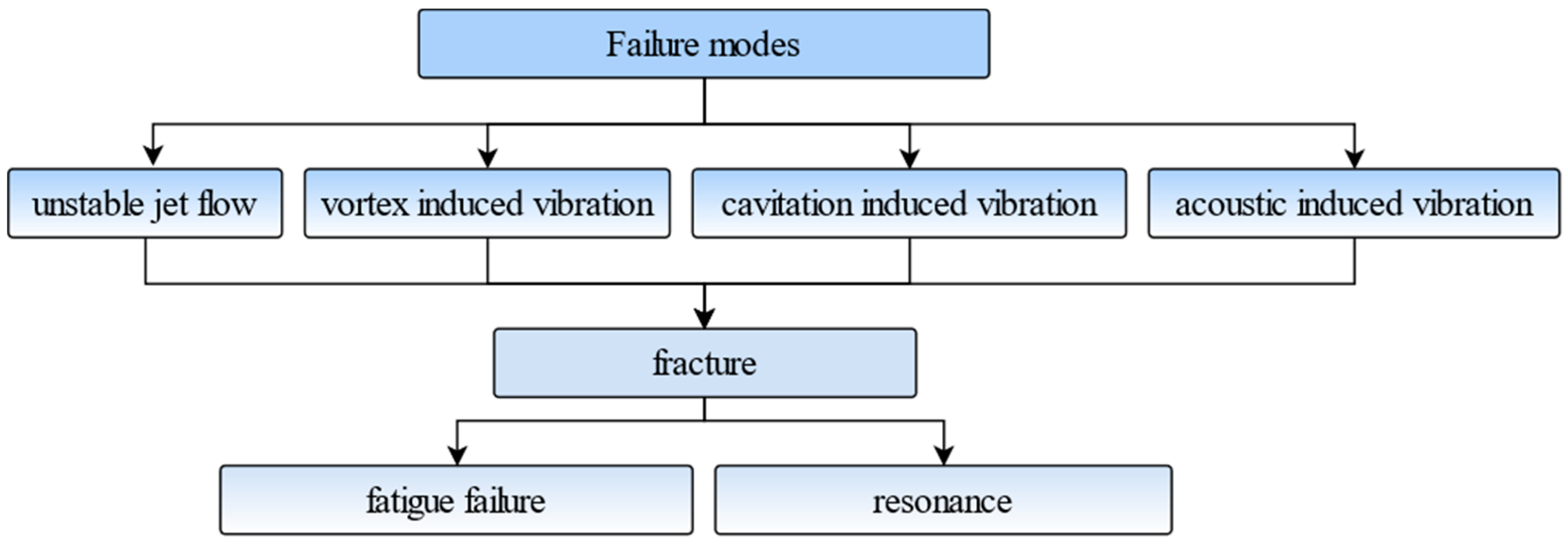
The primary failure modes of control valves involve vibration-induced fatigue and fracture of the moving parts, particularly the valve plug and stem assembly. These failures are often triggered by a combination of fluid dynamics and acoustic phenomena. The key contributing factors include unstable jet flow, vortex shedding, cavitation, and acoustic cavity resonance, all of which can generate significant excitation forces acting on the valve structure.
Vibration fractures frequently occur at the junction between the valve plug and stem, where stress concentrations are high. This is especially common under small valve opening conditions, where the flow instability and associated excitation forces are intensified. In addition, during valve opening or closing, transient flows originating from upstream sources (e.g., pumps and compressors) propagate through the pipeline, inducing high-frequency oscillations in the valve components. These fluid-driven excitations can lead to fatigue failure at the plug–stem connection, particularly under small-opening conditions or during frequent cycling. Furthermore, several influencing parameters—including valve plug geometry, fluid properties, flow direction, and operating conditions—have a critical impact on the vibration behavior of the valve stem. Table 1 summarizes and categorizes the different vibration-related failure modes observed in control valves, along with representative case studies. The mechanisms behind these failures are complex and span multiple disciplines, including fluid mechanics, vibration mechanics, and structural dynamics.
Therefore, a proper understanding of the valve’s structural design, functional principles, and operating environment is essential to accurately analyze the failure process. Figure 2 illustrates a typical example of a vibration-induced failure mode in a control valve.

3. Failure Phenomenon of Flow-Induced Vibration Fatigue Fracture of Control Valves

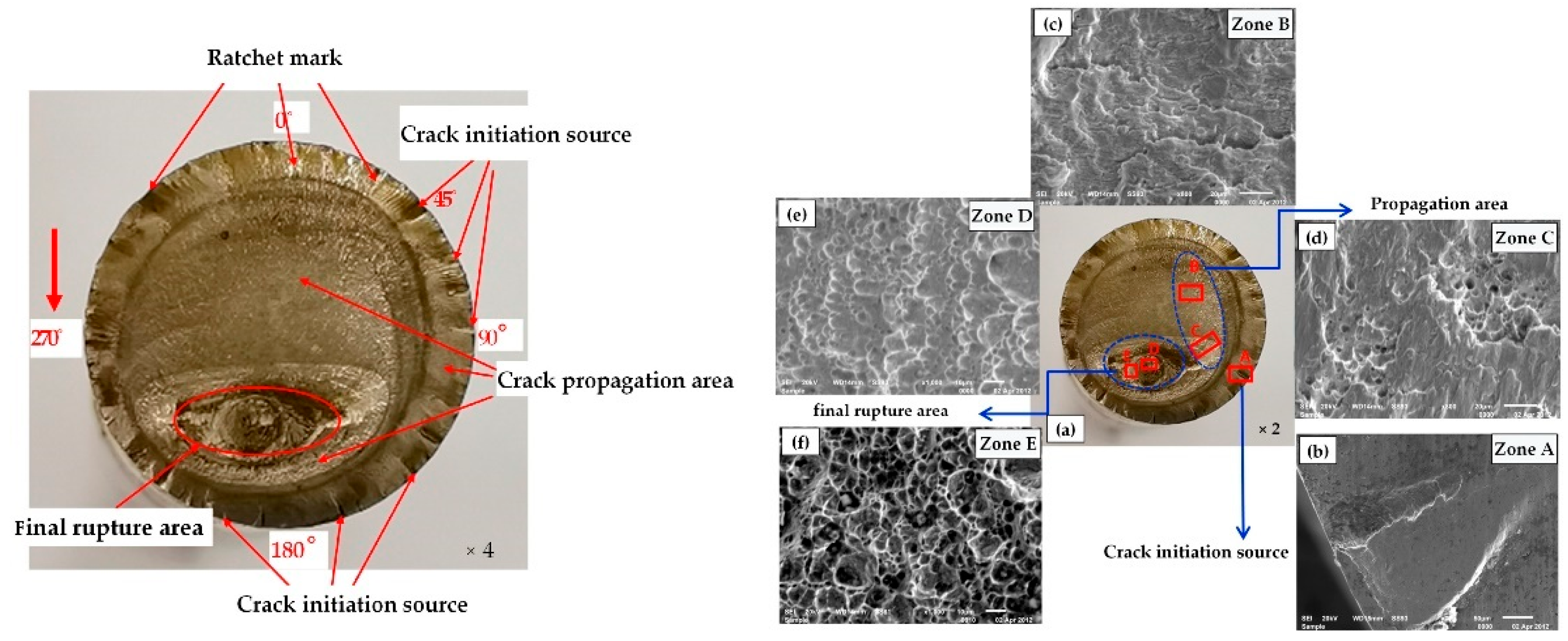
During the operation of a control valve, the valve stem–valve plug moving component is affected by the fluid excitation force, causing vibration fatigue damage and even resonance fracture problems. Experimental investigations combining macro-/micro-fractography, compositional analysis, and microhardness testing [4,61,62,63,64] reveal consistent failure patterns in control valve components. In high-pressure bypass valves operating at 600 °C during plant transients, forensic analysis of stem fractures at valve plug junctions identified bimodal failure signatures: progressive fatigue propagation evidenced by striation morphology, transitioning abruptly to brittle overload fracture with characteristic planar surfaces and minimal plasticity—indicating resonance-driven crack acceleration [62]. Similarly, in petrochemical sulfur recovery units, valve failures under small openings exhibited fracture surfaces inclined at 45° to the stem axis. SEM analysis identified three characteristic zones: Area A: the crack initiation zone at the geometric discontinuity between the stem and plug, marked by fatigue striations; Areas B and C: two distinct fatigue propagation zones with dense, directional striations showing progressive crack growth under cyclic fluid excitation; Areas D and E: final fracture zones, where the crack transitioned to brittle overload failure, exhibiting cleavage-like fracture surfaces and a rough morphology [4]. Coal chemical industry failures further demonstrated synergistic degradation mechanisms, encompassing particulate-induced erosion grooves predominantly observed during high-flow conditions at or above 50% valve opening, cavitation pitting generated by high-pressure differential flows, and fatigue cracks propagating radially from geometric stress concentrators at diameter transitions—a phenomenon particularly prevalent during low-flow operation at or below 40% opening [61]. These fractures invariably initiate at inherent geometric discontinuities such as stem–plug junctions and diameter transition zones, where fluid dynamic forces concentrate cyclic stresses. Diagnostic fractographic signatures consistently feature fatigue striations evidencing progressive crack advancement under sustained fluid excitation. Figure 3 illustrates the macroscopic and microscopic features of such fractures, with SEM micrographs corresponding to the key regions (A–E) discussed above.
In conclusion, the fracture failure of the valve stem and plug motion assembly caused by fluid excitation forces in control valves primarily manifests as the fracture originates at stress concentration areas formed by structural discontinuities, such as at the connection between the valve stem and plug. Obvious striations appear on the fracture surface, showing the progressive expansion of cracks under cyclic fluid excitation forces. Additionally, part of the fracture surface exhibits brittle fracture characteristics at an inclined angle, with a rough surface and relatively flat fracture plane, indicating that during the later stages of crack propagation the material rapidly lost its load-bearing capacity, resulting in a sudden fracture. These characteristics collectively reflect the destructive impact of fluid excitation forces on the valve stem motion assembly.

4. Failure Factors

4.1. Unstable Jet Flow-Induced Vibration

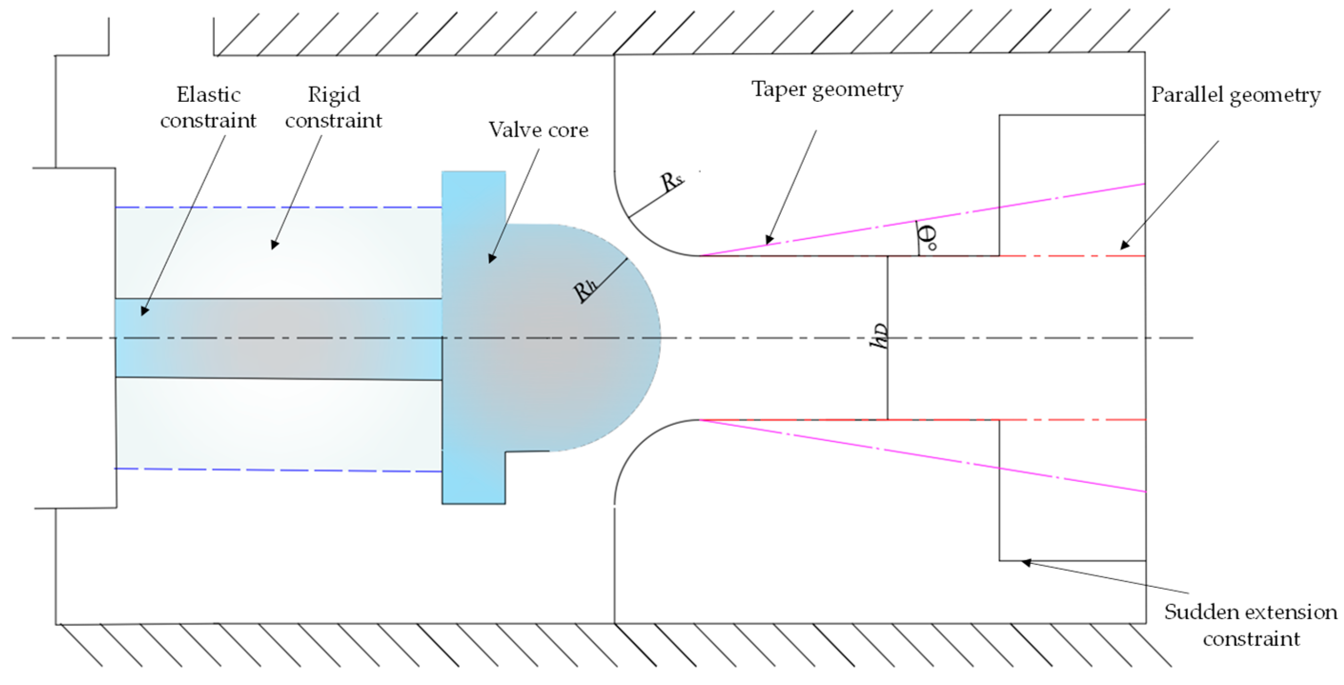
As previously discussed, unstable jet flow is a primary form of fluid-induced excitation in control valve vibration failures, especially under small or partial valve openings. To elaborate on this mechanism, several fluid dynamic phenomena—such as the Coandă effect, supersonic jet expansion, flow separation, shear layer instability, steam-phase expansion, and bubble detachment—can be considered as key contributors to jet unsteadiness [61]. These mechanisms disrupt flow symmetry and create oscillatory jet behavior, resulting in pressure fluctuations and alternating aerodynamic forces on the valve internals. For instance, the Coandă effect causes intermittent jet attachment to the valve wall, while shear layer instability generates broadband turbulence. In compressible fluids like steam, supersonic expansion and bubble separation can further amplify pressure pulsations. Terachi and Okutsu’s team conducted pivotal experimental investigations using a bespoke steam control valve test rig [65,66,67,68]. Figure 4 presents an illustration of schematic combinations of valve plugs and seats under different constraint conditions. Their work combined physical testing—incorporating variations in valve seat geometries, rigid and elastic support conditions, pressure ratios, and valve openings—with CFD simulations [13,27,66,67,68,69] and identified five distinct flow regimes: relatively stable asymmetric continuous flow and symmetric free jets, alongside unstable symmetric oscillation, asymmetric oscillation, and mixed unsteady oscillation. Crucially, they established that transverse fluid forces, generated predominantly by localized high-pressure zones on the valve plug surface, constitute the main excitation source. Furthermore, rigid supports were shown to exacerbate vibration compared to elastic supports, and configurations where the valve plug radius exceeds the valve seat radius heighten susceptibility to transverse forces. Notably, while small vibration displacements correlate with stochastic downstream pressure pulsations, large amplitudes synchronize the downstream flow periodicity with the valve plug vibration frequency, culminating in self-excited vibration.
Complementary studies reinforced the critical role of intrinsic flow instabilities. Hardin et al. [20], employing pressure fluctuation measurements and RANS simulations, demonstrated that valve vibrations stem primarily from flow instabilities largely independent of valve mechanical properties. Consequently, altering valve material, installation fit, or natural frequency proves ineffective in mitigating these recurrent vibration failures. This inherent fluid-driven nature necessitates focus on flow field management. Zaryankin et al. [70], using LES, confirmed a strong correlation between valve vibrations and pressure pulsations, emphasizing that pulsation amplitude depends critically on fluid passage geometry, thereby underscoring the necessity for flow geometry redesign to achieve stability.
Research has further delineated specific mechanisms generating destabilizing forces. Morita et al. [26], combining experiments with LES, identified asymmetric lateral loads on the valve plug due to flow instability as the principal vibration driver. This asymmetry is exacerbated by transonic flow pattern transitions and the dynamic migration of high-pressure zones induced by impinging jets. Zanazzi et al. [17,71] attributed substantial unbalanced forces to the interaction between asymmetric supersonic jets emanating from the shaft-seat gap and downstream diffusers. Similarly, DES analyses by Zeng et al. linked unstable flow patterns and migrating high-pressure zones to low-frequency intermittent vibrations of the valve stem [53]. Domnik et al. [38,50,72,73], utilizing SAS-F simulations, characterized three distinct diffuser flow topologies under varying openings and pressures: fully diffused flow, wall jet flow, and wall-separated jet flow. Significantly, wall jets and off-wall jets under partial obstruction were found to induce substantial stem vibrations.
To resolve the underlying coherent structures driving these forces, Wang Peng et al. [59,60] performed Proper Orthogonal Decomposition (POD) modal analysis on the unsteady flow field. Their results revealed that lateral force fluctuations on the valve plug assembly arise primarily from synchronous and alternating oscillations of the annular wall-mounted jet flow.
Collectively, these investigations underscore that flow-induced instability and vibration in control valves involve intricate, geometry-dependent fluid–structure interactions. Key influencing factors include the design of internal components—such as seat and diffuser profiles and their clearances—as well as operating conditions like pressure ratio, valve opening, and support rigidity. Importantly, mitigation strategies should not rely solely on purely structural modifications (e.g., increasing stiffness or changing material properties), as they may not address the root cause of instability originating from adverse flow behaviors. Instead, effective vibration suppression requires integrated design approaches that simultaneously consider flow field optimization—through geometry refinement, flow path smoothing, and jet deflection—and structural robustness, thereby minimizing excitation sources and enhancing system damping.

4.2. Vortex-Induced Vibration

Under high-pressure operating conditions, fluid passage through pressure-reducing components within control valves can induce periodic vortex shedding in their wake. This shedding possesses a characteristic dominant frequency. A critical concern arises when this vortex-shedding frequency coincides with or approaches a structural natural frequency of the valve assembly, leading to vortex-induced resonance. This resonant condition amplifies displacements and deformations of internal components, generating significant vibration and noise that compromise system integrity and safety.
Valve operation at minimal openings is particularly susceptible. High fluid forces are generated across the throttling region, while turbulent flow past the valve plug–stem structure can trigger vortex formation. The resultant oscillatory forces may excite structural modes, culminating in resonance and potential damage. Butterfly valves exemplify this vulnerability, especially at reduced openings. At small openings, the butterfly valve disc partially obstructs the flow, generating an unsteady wake characterized by alternating vortex shedding from its edges. This phenomenon resembles the von Kármán vortex street observed in bluff body flows, such as external flow over a cylinder. While the internal valve flow is more complex due to geometric confinement and non-uniform inlet profiles, the underlying shedding mechanism remains analogous. Notably, vortex distribution within the valve evolves with opening, and the number of small-scale vortices on the disc surface and downstream diminishes significantly compared to larger openings [74]. Furthermore, jet effects and the premature detachment/collapse of low-temperature cavitation bubbles can enhance turbulence intensity, promoting the shedding of numerous discrete vortices within the flow field.
Under simplified assumptions, the vortex shedding frequency, Fk, may be approximated using the Strouhal relation [75,76,77]:
F k = S t × v T
In the formula: Fk represents the shedding frequency of the von Kármán vortex (Hz), representing the frequency at which vortices are shed from the valve plate due to fluid flow; St is the Strouhal number; v is the velocity of the water flowing past the butterfly plate (m/s); and T is the thickness of the water outlet edge (m). It must be emphasized that this estimation is only valid in idealized flow conditions and is presented here for conceptual illustration. For actual valve flows, precise frequency prediction requires CFD simulation or experimental identification due to complex boundary interactions.
In addition to butterfly valves, other valve types with intricate internal geometries are also susceptible to vortex-induced vibrations (VIVs). Labyrinth-type, cage-with-streamlined-windows, and multi-hole sleeve valves are key examples. In sleeve valves, flow separation occurs at the edges of the throttling elements, such as holes or windows. This separation leads to the formation and alternating shedding of vortices downstream. The fluctuating pressure fields created by these vortices apply periodic forces to the internal structure, resulting in vibrations. Resonance happens when the shedding frequency aligns with a structural natural frequency. The severity of VIVs is typically greatest during valve opening and closing transients or sustained operation at small openings, with flow velocity and pressure differential being the primary influencing factors [78,79,80].

4.3. Cavitation-Induced Vibration

Cavitation flow within industrial plants poses significant risks to equipment and components, manifesting as erosion, noise, and detrimental vibration [81,82,83]. Control valves, ubiquitous in flow regulation, are particularly vulnerable when handling cavitating fluids. While brief exposure may be tolerable, sustained operation under cavitation conditions accelerates damage to critical components like valve plugs and shafts [12,84,85,86]. Consequently, research efforts focus on elucidating cavitation vibration mechanisms and developing predictive models for valve remaining life.
The evolution of cavitation-induced vibration can be predicted via numerical simulation by modeling changes in fluid bulk moduli resulting from the presence and dynamics of cavitation bubbles. Visual experiments reveal the dynamic interplay between control valve spool displacement, cavitation bubble population density, and localized pressure fields near the spool [87,88,89]. Furthermore, analyzing high-frequency components of valve acceleration data, alongside strain and pressure pulsation measurements, establishes correlations between acceleration response and pressure differential across the valve. This approach also identifies distinct characteristics and critical thresholds for cavitation inception [90]. Empirical observations indicate that cavitation initiates when the cavitation coefficient (σ) falls within the range of 0.42 to 0.47. Severe vibration, characterized by a sharp increase in stem displacement amplitude in the flow resistance direction, occurs when σ exceeds 0.8. The cavitation coefficient (σ), defined in this study as
σ = p 1 p v p 1 p 2
where p1 is the upstream pressure, p2 is the downstream pressure, and pv is the vapor pressure of the fluid, serves as an indicator of the cavitation potential within the valve. This definition is consistent with standard formulations used in control valve analysis.
During cavitation-induced vibration, transitions between multiphase (vapor/liquid) and single-phase (liquid) flow regimes induce significant pressure fluctuations within the flow field. These pressure variations drive corresponding oscillations in the cavitation bubble population density. Crucially, the valve spool displacement waveform exhibits a phase lag of approximately one-quarter wavelength relative to the bubble density fluctuation [91]. Pressure surges are prominent during valve opening, while rapid pressure drops occur during closing. This strong temporal correlation identifies bubble population fluctuation as the fundamental driver of cavitation vibration.
The cavitation bubble population density is highly sensitive to downstream pressure. Increasing downstream pressure suppresses cavitation, as evidenced by the release of annular vortices downstream prior to bubble collapse and the eventual elimination of cavitation. From a cavitation–eddy interaction perspective, the periodic structure of cavitation is intrinsically linked to corresponding changes in vortex distribution and the dynamics of large-scale coherent structures. Cavitation intensity is primarily governed by inlet pressure and throttling geometry. Additionally, the position of the control valve within the pipeline can influence local pressure gradients and flow resistance, thereby offering a system-level means to mitigate cavitation-induced vibration. Research further confirms a positive correlation between turbulent jet intensity and cavitation severity. Mitigation strategies exploiting this relationship include perturbing the primary jet—for instance, by introducing continuous microjets of water around its periphery—to suppress cavitation development and reduce associated vibration [92,93].
The effects of the cavitation have been shown by investigating a butterfly valve in cavitating. The spectral properties of the local pressure fluctuations are slightly influenced. However, the level of fluctuation increases at the high frequencies when the cavitation number decreases. And the cavitation induces a decrease in the resonance frequencies. In order to determine the transfer function or the response of frequency, the characteristics of the cavitation area, c, is estimated in [94,95]. The formulation is shown in Equations (2) and (3).
cos ω L c C c ( 1 M 2 ) sin ω ( L 1 + L 2 ) c + sin ω L c C c ( 1 M 2 ) [ C c c cos ω L 1 c cos ω L 2 c c C c cos ω L 1 c cos ω L 2 c ] + i M C c sin ω L 2 c sin ω ( L 2 L 1 ) c = 0
C c = [ 1 α C i 2 ( 1 α + α ρ g ρ 1 ) + α C g 2 ( α + ( 1 α ) ρ 1 ρ g ) ] 1 / 2
where M is the Mach number; L1 is the upstream length of the pipe; L2 is the downstream length of the pipe; and Cc and Lc are, respectively, the sound velocity and the length of the cavitating region. The imaginary term has a small effect and one can suppose that the resonance frequencies are given by the annulment of the real part of this expression, where Cl and Cg are, respectively, the sound velocity in the liquid and the gas and ρl and ρg are, respectively, the mass density in the liquid and the gas.

4.4. Flow-Excited Acoustic Resonance

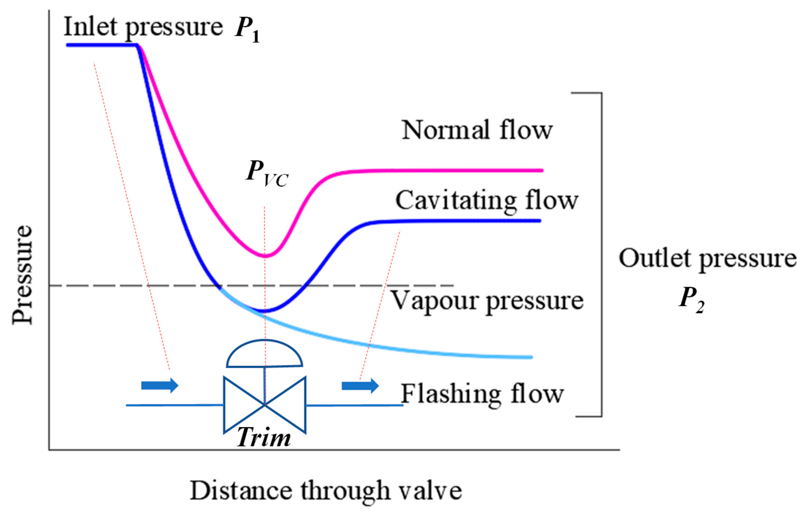
Industrial energy systems frequently operate under high-pressure and high-temperature conditions to maximize efficiency and economic benefit. This high-parameter environment poses significant challenges for local throttling devices, particularly control valves, where the passage of high-pressure fluids can generate complex flow phenomena. These phenomena induce mechanical vibration, flow fluctuations, and intense noise, impacting system stability and environmental compliance. Flow-induced noise encompasses several mechanisms, including turbulence-generated noise, cavitation noise, and flash vaporization noise [96]. When fluid flows through the narrow throttling regions of a control valve, its velocity increases while the pressure drops, according to the principle of energy conservation. If the working fluid is a liquid and the local pressure falls below its vapor pressure, vapor bubbles begin to form—this is commonly referred to as flashing. If the pressure subsequently recovers above the vapor pressure downstream, these vapor bubbles may collapse abruptly, causing cavitation. Figure 5 schematically illustrates this process by showing the typical pressure profile across a control valve. It is important to distinguish between flashing and cavitation: flashing refers to vapor formation due to pressure drop, while cavitation involves vapor collapse and the associated pressure surges and vibrations.
Cavitation noise is a prevalent source, arising when localized fluid pressure drops below the vapor pressure, triggering bubble formation and collapse. This process significantly amplifies fluid velocity, noise levels, and structural vibration [97,98,99,100]. Under specific pressure differentials, a blocked flow condition occurs where the volumetric flow rate saturates despite increasing pressure drop. Concurrently, jet velocities escalate, further depressurizing localized regions. This confirms cavitation as a primary noise generation mechanism. Critically, the intense noise generated downstream can propagate through piping systems, leading to fatigue and failure of pipework and components.
Beyond cavitation, acoustic resonance presents a major vibration hazard. In single-seat control valves operating under high pressure ratios, compressible fluids form supersonic jets at the valve plug throttling point [101]. These jets exhibit inherent instability, featuring complex shock structures and oscillatory behavior. Crucially, this flow instability can couple energetically with the acoustic modes of the valve body or connected piping system, resulting in severe stem vibrations [17,19,41,42]. Field experiments and scaled model studies on turbine control valves demonstrate that internal jet impingement directly excites these acoustic resonances, causing destructive vibrations that damage components like pistons and sleeves.
The acoustic resonance mechanism is further evidenced by experimental studies investigating geometric dependence. Measurements reveal an inverse relationship between the oscillation frequency and the characteristic diameter of the valve chamber. Critically, the observed frequencies align precisely with calculated natural frequencies of the acoustic modes within the system cavity, confirming acoustic resonance as the primary driver of the vibrations [16]. This resonant excitation arises from the interaction of turbulent vortical structures within the flow, generating strong pressure fluctuations capable of exciting longitudinal acoustic modes [15,56]. Such resonances impose severe dynamic loads, posing a significant risk to valve integrity.
Similar phenomena, where intense noise generated at valve restrictions (e.g., body necks) excites downstream piping resonances leading to failure, have been documented [102]. Predicting and mitigating these flow-excited acoustic resonances is therefore paramount for industrial system reliability. Uncontrolled vibrations not only damage the valve itself but also propagate amplified pressure waves through the connected pipe network. This can induce fatigue in critical components like pipe supports, elbows, and instrumentation, ultimately risking system failure.

5. Anti-Vibration Measures

In order to prevent the control valve from breaking and failing due to flow-induced vibration during operation, based on the investigation of control valve flow-induced vibration failure cases and related research, the reasons for the flow-induced vibration failure of the control valve were analyzed, and it was concluded that the following measures can be taken to avoid resonance failure:
  • Change the structural dynamics characteristics of the valve stem moving component: Changing the material of the valve plug–valve stem moving component, increasing the diameter of the valve stem, optimizing the connection method between the valve stem and the valve plug, and adjusting the restraint method of the valve stem can effectively change the natural frequency and vibration shape of its structure. This helps prevent the natural frequency of the valve plug assembly from resonating with the fluid excitation frequency. At the same time, the rigidity of the valve stem is improved and the valve stem’s ability to resist deformation is enhanced, thereby reducing the risk of valve stem breakage caused by flow-induced vibration.
  • Optimize the valve stem structure to avoid local high stress: Optimizing the structure of the valve stem and valve plug, especially smooth transition processing in the connection transition area, can effectively avoid stress concentration. In addition, changing the shape of the valve plug and designing more reasonable flow channels can disperse and reduce local high stress areas.
  • Add damping: Increasing structural damping can significantly improve the system’s ability to absorb vibrations. Damping can be improved by introducing springs, using soft sealing structures, and using packing materials with high friction to attenuate flow-induced vibrations.
  • Change the fluid flow characteristics: The fluid flow characteristics within the control valve can be changed by changing the shape of the orifice or using a different type of valve plug. For example, the use of multi-stage pressure-reducing sleeve control valves can reduce cavitation. The impact force caused by bubble collapse during cavitation is absorbed by the fluid, thereby reducing the vibration caused by cavitation.
Selecting an appropriate control valve type is crucial to mitigating vibration-induced failure. Prior to commissioning, modal and harmonic response analyses should be conducted to evaluate the structural dynamics of the valve assembly. Specifically, it is essential to ensure that the valve’s natural frequencies do not coincide with dominant flow-induced excitation frequencies under expected operating conditions. Valves with inherently higher damping characteristics—such as globe valves with guided stems—may be preferred in high-vibration environments. These design and selection measures help suppress resonance, reduce fatigue risk, and enhance the operational longevity and reliability of the system.

6. Conclusions

This research focuses on the economic losses and safety accidents caused by the vibration and fracture failure of control valve internals in industrial, chemical, and energy sectors. It reviews the phenomena and typical cases of flow-induced vibration fatigue fracture in valve plug–stem assemblies in industrial systems and the main causes of flow-induced vibration failure in control valves, namely, unstable flow, jets, vortices, cavitation, and acoustic cavity resonance.
In addition, the study summarizes key measures to prevent valve stem vibration, aimed at enhancing the operational stability and fatigue life of control valves. From the reviewed research, the following conclusions were reached: Fracture failure in control valve stems due to fluid excitation primarily presents as cracks originating from structural discontinuities at the valve stem–plug connection, with progressive crack propagation under cyclic fluid excitation, and brittle fracture characteristics at an inclined angle.
Unstable flow and the vibration phenomena it induces in control valves involve complex fluid dynamics mechanisms, primarily due to flow instability. These include five flow modes: asymmetric continuous flow, symmetric free jets, symmetric oscillation, asymmetric oscillation, and mixed unsteady oscillation. The synchronized and alternating oscillations of annular wall-attached and detached flows exacerbate the vibration of the valve plug–stem assembly. These effects are closely related to valve geometry, flow conditions, and support methods.
Labyrinth-type, profiled-window, multi-hole sleeve, and butterfly valves are susceptible to vortex-induced vibrations at small openings. As fluid passes through pressure-reducing components, periodic vortices may form in the wake, exerting alternating forces on the internal structures of the valve. If the primary frequency of vortex shedding matches or is close to the valve’s modal frequency, vortex-induced resonance may occur.
Cavitation intensity in control valves primarily depends on the inlet pressure and throttle diameter. Fluctuations in cavitation bubble populations are regarded as a key contributor to vibration in the valve stem assembly. From the perspective of cavitation–vortex interaction, periodic cavitation structures are closely associated with changes in vortex distribution and the presence of large-scale vortices. Similarly, in cavitation–jet interaction, cavitation intensity is positively correlated with jet strength. To mitigate cavitation effects, continuous microjets can be introduced around the main jet. Moreover, calculating cavitation area parameters and the corresponding resonance frequency aids in characterizing cavitation behavior and informing structural design improvements.
Jets, turbulence, and cavitation flow within control valves are the main sources of noise. Compressible fluids form supersonic jets at the throttle, and the resulting multiple shock waves and jet instability excite structural acoustic modes, which are a primary cause of vibration. Vortex interactions generate intense noise, exciting longitudinal acoustic modes, which also contribute to vibration-induced damage to the valve. Additionally, the flow noise produced by the valve may excite downstream piping acoustic modes, leading to damage in downstream components.
To avoid fracture failure of the control valve stem motion assembly caused by flow-induced vibration during operation, measures such as selecting the appropriate type of control valve, changing the dynamic characteristics of the stem–plug motion assembly, optimizing the valve stem structure to reduce localized high stress, adding damping, and altering the fluid flow characteristics within the valve can help. These actions prevent the vibration-induced fracture of the stem motion assembly, extend the control valve’s service life, and improve its overall reliability.

Author Contributions

Conceptualization, L.Y.; methodology, S.L.; writing—original draft preparation, L.Y.; writing—review and editing, J.H.; formal analysis, L.Y.; investigation, J.H. and L.Y.; supervision, L.Y. and S.L. All authors have read and agreed to the published version of the manuscript.

Funding

This research was funded by a program for the National Natural Science Foundation of China (Research Project: 51569012); Gansu Province Science and Technology Program Funding: Grant No. 22CX8GA125; and the Gansu Provincial Education Department: Industry Support Plan Project 2025CYZC-04.

Conflicts of Interest

The authors declare no conflicts of interest.

References

  1. Anilkumar, A.; Kartik, V. Eigen and temporal characteristics of multi-frequency parametrically-excited rotor-oscillator systems. J. Sound Vib. 2021, 493, 115824. [Google Scholar] [CrossRef]
  2. Chen, F.; Liu, H.; Zhang, S. Time-adaptive loosely coupled analysis on fluid-thermal-structural behaviors of hypersonic wing structures under sustained aeroheating. Aerosp. Sci. Technol. 2018, 78, 620–636. [Google Scholar] [CrossRef]
  3. Chizfahm, A.; Yazdi, E.A.; Eghtesad, M. Dynamic modeling of vortex induced vibration wind turbines. Renew. Energy 2018, 121, 632–643. [Google Scholar] [CrossRef]
  4. Guo, F.; Lyu, Y.; Duan, Z.; Fan, Z.; Li, W.; Chen, F. Analysis of Regulating Valve Stem Fracture in a Petrochemical Plant. Processes 2023, 11, 1106. [Google Scholar] [CrossRef]
  5. El Bouzidi, S.; Hassan, M.; Ziada, S. Experimental characterisation of the self-excited vibrations of spring-loaded valves. J. Fluids Struct. 2018, 76, 558–572. [Google Scholar] [CrossRef]
  6. El Bouzidi, S.; Hassan, M.; Ziada, S. Self-excited vibrations of spring-loaded valves operating at small pressure drops. J. Fluids Struct. 2018, 83, 72–90. [Google Scholar] [CrossRef]
  7. Duan, Y.; Revell, A.; Sinha, J.; Hahn, W. A computational fluid dynamics (CFD) analysis of fluid excitations on the spindle in a high-pressure valve. Int. J. Press. Vessel. Pip. 2019, 175, 103922. [Google Scholar] [CrossRef]
  8. Haimin, W.; Feng, H.; Xiangshuai, K.; Si, C. Pressure fluctuation of steam on the disc in a triple eccentric butterfly valve. SN Appl. Sci. 2020, 2, 1193. [Google Scholar] [CrossRef]
  9. Liu, J.; Chen, X.; Han, C.; Ma, X.; Wu, F. Analysis on flow induced vibration of main steam bypass valve in a nuclear power plant. J. Phys. Conf. Ser. 2021, 1985, 012027. [Google Scholar] [CrossRef]
  10. Liu, S.; Huang, X.; Feng, Z.; Jiang, X.; Wang, B.; Wu, W. Study on Flow-Induced Vibration of Self-Regulation Check Valve During Opening. Press. Vessel. Pip. Conf. 2021, 85352, V005T007A012. [Google Scholar]
  11. Sun, X.; Li, X.; Zheng, Z.; Huang, D. Fluid–structure interaction analysis of a high-pressure regulating valve of a 600-MW ultra-supercritical steam turbine. Proc. Inst. Mech. Eng. Part A J. Power Energy 2015, 229, 270–279. [Google Scholar] [CrossRef]
  12. Wei, A.-B.; Gao, R.; Zhang, W.; Wang, S.-H.; Zhou, R.; Zhang, X.-B. Computational fluid dynamics analysis on flow-induced vibration of a cryogenic poppet valve in consideration of cavitation effect. J. Zhejiang Univ.-Sci. A 2022, 23, 83–100. [Google Scholar] [CrossRef]
  13. Yonezawa, K.; Ogawa, R.; Ogi, K.; Takino, T.; Tsujimoto, Y.; Endo, T.; Tezuka, K.; Morita, R.; Inada, F. Flow-induced vibration of a steam control valve. J. Fluids Struct. 2012, 35, 76–88. [Google Scholar] [CrossRef]
  14. Zeid, A.; Shouman, M. Flow-induced vibration on the control valve with a different concave plug shape using FSI simulation. Shock Vib. 2019, 2019, 8724089. [Google Scholar] [CrossRef]
  15. Widell, K.-E. Governing valve vibrations in a large steam turbine. In Practical Experiences With Flow-Induced Vibrations; Springer: Berline/Heidelberg, Germany, 1980; pp. 320–322. [Google Scholar] [CrossRef]
  16. Nakano, M.; Outa, E.; Tajima, K. Noise and vibration related to the patterns of supersonic annular flow in a pressure reducing gas valve. J. Fluids Eng. 1988, 110, 55–61. [Google Scholar] [CrossRef]
  17. Ziada, S.; Bühlmann, E.; Bolleter, U. Flow impingement as an excitation source in control valves. J. Fluids Struct. 1989, 3, 529–549. [Google Scholar] [CrossRef]
  18. Pluviose, M. Stabilization of flow through steam-turbine control valves. J. Eng. Gas Turbines Power. 1989, 111, 642–646. [Google Scholar] [CrossRef]
  19. Michaud, S.; Ziada, S.; Pastorel, H. Acoustic fatigue of a steam dump pipe system excited by valve noise. J. Press. Vessel Technol. 2001, 123, 461–468. [Google Scholar] [CrossRef]
  20. Hardin, J.R.; Kushner, F.; Koester, S. Elimination of Flow-Induced Instability from Steam Turbine Control Valves; Texas A&M University: College Station, TX, USA, 2003. [Google Scholar]
  21. Stastny, M.; Bednar, L.; Tajc, L.; Kolar, P.; Martinu, P.; Matas, R. Pulsating flows in the inlet of a nuclear steam turbine. In Proceedings of the 5th European Conference on Turbomachinery, Fluid Dynamics and Thermodynamics, Prague, Czech Republic, 18–21 March 2003; pp. 17–22. [Google Scholar]
  22. Zhang, D.; Engeda, A.; Hardin, J.; Aungier, R. Experimental study of steam turbine control valves. Proc. Inst. Mech. Eng. Part C J. Mech. Eng. Sci. 2004, 218, 493–507. [Google Scholar] [CrossRef]
  23. Zhang, D.; Engeda, A. Vent uri valves for steam turbines and improved design considerations. Proc. Inst. Mech. Eng. Part A J. Power Energy 2003, 217, 219–230. [Google Scholar] [CrossRef]
  24. Morita, R.; Inada, F.; Mori, M.; Tezuka, K.; Tsujimoto, Y. CFD calculation and experiments of unsteady flow on control valve. Heat Transf. Summer Conf. 2004, 46911, 51–58. [Google Scholar]
  25. Morita, R.; Inada, F.; Mori, M.; Tezuka, K.; Tsujimoto, Y. Flow induced vibration of a steam control valve in middle-opening condition. ASME Press. Vessel. Pip. Conf. 2005, 41898, 485–490. [Google Scholar]
  26. Morita, R.; Inada, F.; Mori, M.; Tezuka, K.; Tsujimoto, Y. CFD simulations and experiments of flow fluctuations around a steam control valve. J. Fluids Eng. 2007, 129, 48–54. [Google Scholar] [CrossRef]
  27. Yonezawa, K.; Toyohira, Y.; Nagashima, T.; Tsujimoto, Y.; Tezuka, K.; Mori, M.; Morita, R.; Inada, F. An experimental study of unsteady transonic flow in a steam control valve with simple model. J. Environ. Eng. 2010, 5, 134–143. [Google Scholar] [CrossRef]
  28. Zanazzi, G.; Schaefer, O.; Sell, M.; Ridoutt, C. Unsteady CFD simulation of control valve in throttling conditions and comparison with experiments. In Proceedings of the ASME Turbo Expo 2013: Turbine Technical Conference and Exposition, San Antonio, TX, USA, 3–7 June 2013; p. V05BT25A019. [Google Scholar]
  29. Janzen, V.P.; Smith, B.A.; Luloff, B.V.; Pozsgai, J.; Dietrich, A.R.; Bouvier, J.M.; Errett, A.J.; Kitko, G.T.; Roberts, T.C. Acoustic noise reduction in large-diameter steam-line gate valves. ASME Press. Vessel. Pip. Conf. 2007, 42827, 513–522. [Google Scholar]
  30. Zaryankin, A.; Arianov, S.; Paramonov, A.; Gotovtsev, A.; Storozhuk, S. A new control valve with a push rod for intermediate-pressure cylinders of steam turbines. Therm. Eng. 2007, 54, 879–885. [Google Scholar] [CrossRef]
  31. Liu, G.; Wang, S.; Guo, H.; Mao, J.; Feng, Z.; Xiang, X. Investigation on flow characteristics and stability of control valves for steam turbines. In Proceedings of the ASME Turbo Expo 2008: Power for Land, Sea, and Air, Berlin, Germany, 9–13 June 2008; pp. 811–820. [Google Scholar]
  32. Tecza, J.; Chochua, G.; Moll, R. Analysis of fluid-structure interaction in a steam turbine throttle valve. In Proceedings of the ASME Turbo Expo 2010: Power for Land, Sea, and Air, Glasgow, UK, 14–18 June 2010; pp. 2329–2338. [Google Scholar]
  33. Clari, M.B.; Polklas, T.; Joos, F. Three-dimensional flow separations in the diffuser of a steam turbine control valve. In Proceedings of the ASME 2011 Turbo Expo: Turbine Technical Conference and Exposition, Vancouver, BC, Canada, 6–10 June 2011; pp. 2327–2334. [Google Scholar]
  34. Lindqvist, H. CFD simulation on flow induced vibrations in high pressure control and emergency stop turbine valve. In Proceedings of the NURETH-14: 14. International Topical Meeting on Nuclear Reactor Thermalhydraulics, Toronto, ON, Canada, 25–30 September 2011. [Google Scholar]
  35. Engeda, A. Performance study and instability analysis of steam turbine control valve. In Proceedings of the ASME Turbo Expo 2012: Turbine Technical Conference and Exposition, Copenhagen, Denmark, 11–15 June 2012; pp. 651–661. [Google Scholar]
  36. Hajšman, M.; Kovandová, D.; Matas, R. Some aspects of numerical simulation of control valves for steam turbines. EPJ Web Conf. 2012, 25, 01052. [Google Scholar] [CrossRef]
  37. Matas, R.; Straka, F.; Hoznedl, M. Numerical simulation of flow and determination of aerodynamic forces in the balanced control valve. EPJ Web Conf. 2013, 45, 01062. [Google Scholar] [CrossRef]
  38. Barannyk, O.; Oshkai, P. Investigation of diametral acoustic modes in a model of a steam control gate valve. J. Press. Vessel Technol. 2014, 136, 061302. [Google Scholar] [CrossRef]
  39. Bianchini, C.; Da Soghe, R.; Cosi, L.; Imparato, E. Numerical analysis of the unsteady loads on a steam turbine double seat control valve. In Proceedings of the ASME Turbo Expo 2014: Turbine Technical Conference and Exposition, Düsseldorf, Germany, 16–20 June 2014; p. V01BT27A048. [Google Scholar]
  40. Bianchini, C.; Da Soghe, R.; Imparato, E.; Cosi, L. Aeroacoustic analysis of a steam turbine double seat control valve. In Proceedings of the 11th European Conference on Turbomachinery Fluid Dynamics & Thermodynamics ETC11, Madrid, Spain, 23–27 March 2015. [Google Scholar]
  41. Brüggemann, P.; Vinnemeier, P.; Balkowski, I.; Büscher, C.; Stapper, P.; Zimmer, G.; Wirsum, M. A new emergency stop and control valves design: Part 1—Experimental verification with scaled models. In Proceedings of the ASME Turbo Expo 2014: Turbine Technical Conference and Exposition, Düsseldorf, Germany, 16–20 June 2014; p. V01BT27A001. [Google Scholar]
  42. Musch, C.; Deister, F.; Zimmer, G.; Balkowski, I.; Brüggemann, P.; Haslinger, W. A new emergency stop and control valve design: Part 2—Validation of numerical model and transient flow physics. In Proceedings of the ASME Turbo Expo 2014: Turbine Technical Conference and Exposition, Düsseldorf, Germany, 16–20 June 2014; p. V01BT27A002. [Google Scholar]
  43. Chakrabarti, S.; Potdar, Y.; Baik, S.; Welch, D.; Forte, G. Forced Response Analysis of Steam Turbine Inlet Flow Control Valves. In Proceedings of the ASME Turbo Expo 2014: Turbine Technical Conference and Exposition, Düsseldorf, Germany, 16–20 June 2014; p. V07BT35A023. [Google Scholar]
  44. Domnick, C.; Benra, F.; Dohmen, H.; Musch, C. Numerical investigation on under expanded wall jet separation in a steam turbine valve diffuser. In Proceedings of the International Symposium on Rotating Machinery ISROMAC-15, Honolulu, HI, USA, 24–28 February 2014. [Google Scholar]
  45. Domnick, C.B.; Benra, F.-K.; Brillert, D.; Dohmen, H.J.; Musch, C. Numerical investigation on the time-variant flow field and dynamic forces acting in steam turbine inlet valves. J. Eng. Gas Turbines Power 2015, 137, 081601. [Google Scholar] [CrossRef]
  46. Domnick, C.B.; Benra, F.-K.; Brillert, D.; Dohmen, H.J.; Musch, C. Improving the design of steam turbine inlet valves by numerical methods for enhanced part load operation. In Proceedings of the 11th European Conference on Turbomachinery Fluid dynamics & Thermodynamics, Madrid, Spain, 23–27 March 2015. [Google Scholar]
  47. Domnick, C.; Benra, F.; Brillert, D.; Dohmen, H.; Musch, C. Numerical Investigation of the Fluid and Structure Dynamics of a Steam Turbine Inlet Valve at Different Operation Conditions. In Proceedings of the VKI Workshop on Safety and Control Valves, Von Kármán Institute, Sint Genesius Rhode, Belgium, 8–9 April 2015. [Google Scholar]
  48. Domnick, C.B.; Benra, F.-K.; Brillert, D.; Dohmen, H.J.; Musch, C. Numerical investigation on the vibration of steam turbine inlet valves and the feedback to the dynamic flow field. In Proceedings of the ASME Turbo Expo 2015: Turbine Technical Conference and Exposition, Montreal, QC, Canada, 15–19 June 2015; p. V008T026A004. [Google Scholar]
  49. Domnick, C.B.; Benra, F.-K.; Brillert, D.; Musch, C. Modification of a steam valve diffuser for enhanced full load and part load operation using numerical methods. Period. Polytech. Mech. Eng. 2016, 60, 185–192. [Google Scholar] [CrossRef]
  50. Domnick, C.B.; Benra, F.-K.; Brillert, D.; Dohmen, H.J.; Musch, C. Investigation on flow-induced vibrations of a steam turbine inlet valve considering fluid–structure interaction effects. J. Eng. Gas Turbines Power 2017, 139, 022507. [Google Scholar] [CrossRef]
  51. Domnick, C.B.; Brillert, D.; Musch, C.; Benra, F.-K. Clarifying the physics of flow separations in steam turbine inlet valves at part load operation and improved design considerations. J. Fluids Eng. 2017, 139, 081105. [Google Scholar] [CrossRef]
  52. Schramm, A.; Müller, T.; Polklas, T.; Brunn, O.; Mailach, R. Unsteady Flow in Extraction Modules of Industrial Steam Turbines. In Proceedings of the ASME Turbo Expo 2014: Turbine Technical Conference and Exposition, Düsseldorf, Germany, 16–20 June 2014; p. V01BT27A009. [Google Scholar]
  53. Zeng, L.-F.; Liu, G.-W.; Mao, J.-R.; Wang, S.-S.; Zhang, C.; Yu, X.; Zhang, J.-J.; Xu, Y.-T. Research on the coupling mechanism between alternating flow pattern and valve stem system of steam turbine control valve. In Proceedings of the ASME Turbo Expo 2014: Turbine Technical Conference and Exposition, Düsseldorf, Germany, 16–20 June 2014; p. V01BT27A049. [Google Scholar]
  54. Zanazzi, G.; Rice, T.; Sell, M.; Ridoutt, C. Experimental and numerical investigation into the aerodynamics of a novel steam turbine valve and its field application. J. Eng. Gas Turbines Power 2014, 136, 091601. [Google Scholar] [CrossRef]
  55. Bianchini, C.; Da Soghe, R.; Cosi, L.; Imparato, E. Aeroacoustic computational analysis of a steam turbine trip valve. In Proceedings of the ASME Turbo Expo 2015: Turbine Technical Conference and Exposition, Montreal, QC, Canada, 15–19 June 2015; p. V008T026A014. [Google Scholar]
  56. Bolin, C.; Engeda, A. Analysis of flow-induced instability in a redesigned steam control valve. Appl. Therm. Eng. 2015, 83, 40–47. [Google Scholar] [CrossRef]
  57. Zeng, L.; Liu, G.; Mao, J.; Yuan, Q.; Wang, S.; Wei, L.; Wang, Z. A novel numerical simulation method to verify turbulence models for predicting flow patterns in control valves. J. Fluid Sci. Technol. 2015, 10, JFST0007. [Google Scholar] [CrossRef]
  58. Zeß, J.-P.; Polklas, T.; Joos, F. Experimental Investigation of the Flow in a Control Valve of an Industrial Steam Turbine. In Proceedings of the ASME Turbo Expo 2016: Turbomachinery Technical Conference and Exposition, Seoul, Republic of Korea, 13–17 June 2016; p. V008T026A028. [Google Scholar]
  59. Wang, P.; Liu, Y. Influence of a circular strainer on unsteady flow behavior in steam turbine control valves. Appl. Therm. Eng. 2017, 115, 463–476. [Google Scholar] [CrossRef]
  60. Wang, P.; Liu, Y. Unsteady flow behavior of a steam turbine control valve in the choked condition: Field measurement, detached eddy simulation and acoustic modal analysis. Appl. Therm. Eng. 2017, 117, 725–739. [Google Scholar] [CrossRef]
  61. Jin, H.; Zheng, Z.; Ou, G.; Zhang, L.; Rao, J.; Shu, G.; Wang, C. Failure analysis of a high pressure differential regulating valve in coal liquefaction. Eng. Fail. Anal. 2015, 55, 115–130. [Google Scholar] [CrossRef]
  62. Zhou, C.L.; Yan, A.J.; Wei, X.; Fan, Z.D.; Zhu, L. Fracture Failure Analysis of a High-Pressure Bypass Valve Stem. J. Fail. Anal. Prev. 2023, 23, 1038–1045. [Google Scholar] [CrossRef]
  63. Yi, J.; Hu, H.; Zheng, Y.; Zhang, Y. Experimental and computational failure analysis of a high pressure regulating valve in a chemical plant. Eng. Fail. Anal. 2016, 70, 188–199. [Google Scholar] [CrossRef]
  64. Kwon, O.G.; Han, M.S. Failure analysis of the exhaust valve stem from a Waukesha P9390 GSI gas engine. Eng. Fail. Anal. 2004, 11, 439–447. [Google Scholar] [CrossRef]
  65. Okutsu, R.; Kuramochi, S.; Outa, E.; Machiyama, T. Noise and Vibration Induced by Throttling of High Pressure Compressible Fluid: Part 1-Characteristics of Noise and Vibration Generated by Cage-guided Control Valve. Bull. JSME 1985, 28, 837–845. [Google Scholar] [CrossRef]
  66. Yonezawa, K.; Nakajima, T.; Toyohira, Y.; Tsujimoto, Y.; Morita, R.; Tezuka, K.; Mori, M. A two-dimensional study of scale effects of flow oscillation in a steam control valve. Nippon. Kikai Gakkai Ronbunshu B Hen 2006, 72, 2172–2177. [Google Scholar] [CrossRef]
  67. Terachi, Y.; Yonezawa, K.; Tsujimoto, Y.; Yokota, K.; Tezuka, K.; Mori, M.; Morita, R. A study of flow induced vibration in a steam control valve. Nippon Kikai Gakkai Ronbunshu B Hen 2004, 70, 371–379. [Google Scholar] [CrossRef]
  68. Yonezawa, K.; Toyohira, Y.; Ichida, Y.; Ogawa, R.; Tsujimoto, Y.; Tezuka, K.; Mori, M.; Morita, R.; Inada, F. A Study of Transonic Flow Fluctuation in Steam Control Valve and Pressure Fluctuation in Downstream Pipe. Trans. Jpn. Soc. Mech. Eng. Ser. B 2008, 74, 286–294. [Google Scholar] [CrossRef]
  69. Yonezawa, K.; Ogawa, R.; Ogi, K.; Takino, T.; Tsujimoto, Y.; Endo, T.; Tezuka, K.; Morita, R.; Inada, F. Flow-induced vibration of valve head of steam control valve. Nippon Kikai Gakkai Ronbunshu B Hen 2011, 77, 1098–1110. [Google Scholar] [CrossRef]
  70. Zaryankin, A.; Zroichikov, N.; Paramonov, A.; Noskov, V.; Grigor’ev, E.Y. Pressure pulsations in the turbine steam-admission path and their influence on the vibration state of the turbine control valves. Therm. Eng. 2012, 59, 106–112. [Google Scholar] [CrossRef]
  71. Sirovich, L. Turbulence and the Dynamics of Coherent Structures. 1. Coherent Structures. Q. Appl. Math. 1987, 45, 561–571. [Google Scholar] [CrossRef]
  72. Barbieri, R.; Barbieri, N. Finite element acoustic simulation based shape optimization of a muffler. Appl. Acoust. 2006, 67, 346–357. [Google Scholar] [CrossRef]
  73. Zhang, Q.S.; Liu, Y.Z. Wall-pressure fluctuations of separated and reattaching flow over blunt plate with chord-to-thickness ratio. Exp. Therm. Fluid Sci. 2012, 42, 125–135. [Google Scholar] [CrossRef]
  74. Zhang, G.; Wang, W.W.; Wu, Z.Y.; Kim, H.D.; Lin, Z. Effect of the opening degree on evolution of cryogenic cavitation through a butterfly valve. Energy 2023, 283, 128543. [Google Scholar] [CrossRef]
  75. Wang, H.; Kong, X.; Liu, H. Vibration characteristics analysis for a tri-eccentric butterfly valve. J. Vib. Shock 2018, 37, 202–212. [Google Scholar]
  76. Hasan, A.; Matsuo, S.; Setoguchi, T.; Kim, H. Transonic moist air flow around a symmetric disc butterfly valve with non-equilibrium condensation. Proc. Inst. Mech. Eng. Part C J. Mech. Eng. Sci. 2010, 224, 2165–2179. [Google Scholar] [CrossRef]
  77. Xu, D.; Ge, C.; Li, Y.; Liu, Y. Evaluation the possibility of vortex-induced resonance for a multistage pressure reducing valve. PLoS ONE 2022, 17, e0266414. [Google Scholar] [CrossRef] [PubMed]
  78. Li, S.; Zhang, W.; Wang, W.; Xu, X.; Zhu, L. Simulation for VIV of high pressure drop labyrinth-sleeve combined regulating valves. J. Vib. Shock 2020, 39, 95–103. [Google Scholar]
  79. Li, S.; Kang, Y.; Meng, L.; Pan, W.; Zhang, W.; Liu, T. Flow-induced noise of a high pressure drop control valve. J. Vib. Shock 2020, 39, 116–121. [Google Scholar]
  80. Qiu, C.; Jiang, C.-H.; Zhang, H.; Wu, J.-Y.; Jin, Z.-J. Pressure drop and cavitation analysis on sleeve regulating valve. Processes 2019, 7, 829. [Google Scholar] [CrossRef]
  81. Au-Yang, M.; Kirk, R. Flow-induced vibration of power and process plant components: A practical workbook. Appl. Mech. Rev. 2002, 55, B64. [Google Scholar] [CrossRef]
  82. Moussou, P.; Papaconstantinou, T.; Cohen, J. Scaling the Vibrations of Water Pipes: Application to Industrial Case Studies. ASME Press. Vessel. Pip. Conf. 2006, 47888, 389–396. [Google Scholar]
  83. Yang, B.-S.; Hwang, W.-W.; Ko, M.-H.; Lee, S.-J. Cavitation detection of butterfly valve using support vector machines. J. Sound Vib. 2005, 287, 25–43. [Google Scholar] [CrossRef]
  84. Yuzawa, S.; Okutsu, R.; Hashizume, T.; Outa, E. Cavitation erosion features in industrial control valves at an inlet pressure of 20 MPa. JSME Int. J. Ser. B Fluids Therm. Eng. 1998, 41, 1105–1113. [Google Scholar] [CrossRef]
  85. Yuzawa, S.; Okutsu, R.; Hashizume, T.; Outa, E. Development of Cavitation Erosion on a Contoured Plug in High Pressure Control Valves. Nihon Kikai Gakkai Ronbunshu B Hen/Trans. Jpn. Soc. Mech. Eng. Part B 2002, 68, 1697–1705. [Google Scholar] [CrossRef]
  86. Yi, D.; Lu, L.; Zou, J.; Fu, X. Interactions between poppet vibration and cavitation in relief valve. Proc. Inst. Mech. Eng. Part C J. Mech. Eng. Sci. 2015, 229, 1447–1461. [Google Scholar] [CrossRef]
  87. Inoue, F.; Outa, E.; Tajima, K.; Machiyama, T. An Experimental Study on Control Valve Cavitation (2nd Report, String Bubble Cavitation in Contoured-plug Valve). Trans. Jpn. Soc. Mech. Eng. 1991, 57, 7–15. [Google Scholar] [CrossRef]
  88. Inoue, F. An Experimenttal Study on Control Valve Cavitation (3rd Report, Vortex Shedding and Cavitation Inception on a Contoured Plug). Trans. JSME 1993, 59, 131–138. [Google Scholar] [CrossRef]
  89. Kumagai, K.; Ryu, S.; Ota, M.; Maeno, K. Investigation of poppet valve vibration with cavitation. Int. J. Fluid Power 2016, 17, 15–24. [Google Scholar] [CrossRef]
  90. Fumihiro, I.; Eisuke, O.; Kiyohiro, T.; Tadahiro, M. An Experimental Study on Control Valve Cavitation: 1st Report, Diagnostics of Cavitation Vibration at High Pressure Reduction and at Low Valve Opening. JSME Int. J. Bull. JSME 1987, 30, 1501. [Google Scholar]
  91. Yang, Q.; Aung, N.Z.; Li, S. Confirmation on the effectiveness of rectangle-shaped flapper in reducing cavitation in flapper–nozzle pilot valve. Energy Convers. Manag. 2015, 98, 184–198. [Google Scholar] [CrossRef]
  92. Yang, H.; Wang, W.; Lu, K.; Chen, Z. Cavitation reduction of a flapper-nozzle pilot valve using continuous microjets. Int. J. Heat Mass Transf. 2019, 133, 1099–1109. [Google Scholar] [CrossRef]
  93. Watanabe, M.; Nishino, K.; Kitajima, Y.; Yonekura, K.; Hagiwara, T. Flow-induced vibration of a control valve in a cavitating flow. ASME Press. Vessel. Pip. Conf. 2009, 43673, 239–246. [Google Scholar]
  94. Hassis, H.; Lauro, J.; Boyer, A.; Dueymes, E. Noise Caused by Cavitating Butterfly and Monovar Valves. Effects of Cavitation on Acoustic Sources; Numerical Simulation; Electricite de France (EDF): Paris, France, 1996. [Google Scholar]
  95. Hassis, H. Noise caused by cavitating butterfly and monovar valves. J. Sound Vib. 1999, 225, 515–526. [Google Scholar] [CrossRef]
  96. Sotoodeh, K. The mathematical analysis and review of noise in industrial valves. JMST Adv. 2022, 4, 45–55. [Google Scholar] [CrossRef]
  97. Merrick, R. Globe Valves-A New Standard. In Proceedings of the Valve World Conference, Asia, Suzhou, China, 23–24 September 2015. [Google Scholar]
  98. Sotoodeh, K. Cavitation in globe valves and solutions. Valve World Mag. 2016, 21, 32–36. [Google Scholar]
  99. Sotoodeh, K. Selecting a butterfly valve instead of a globe valve for fluid control in a utility service in the offshore industry (based on an industrial experience). Am. J. Mech. Eng. 2018, 6, 27–31. [Google Scholar] [CrossRef]
  100. Solutions, E.A. Control Valve Handbook; Fisher Controls International: Marshalltown, IA, USA, 2017. [Google Scholar]
  101. Semrau, S.; Skoda, R.; Wustmann, W.; Habr, K. Experimental and numerical investigation of noise generation due to acoustic resonance in a cavitating valve. J. Sound Vib. 2019, 463, 114956. [Google Scholar] [CrossRef]
  102. Shioyama, T.; Asakura, D.; Kobayashi, T.; Iseki, T.; Hosaka, H. Coupling vibrations between pipe wall and internal higher-order acoustic wave caused by valve choking. Trans. Jpn. Soc. Mech. Eng. Part C 1995, 61, 3450–3455. [Google Scholar] [CrossRef]
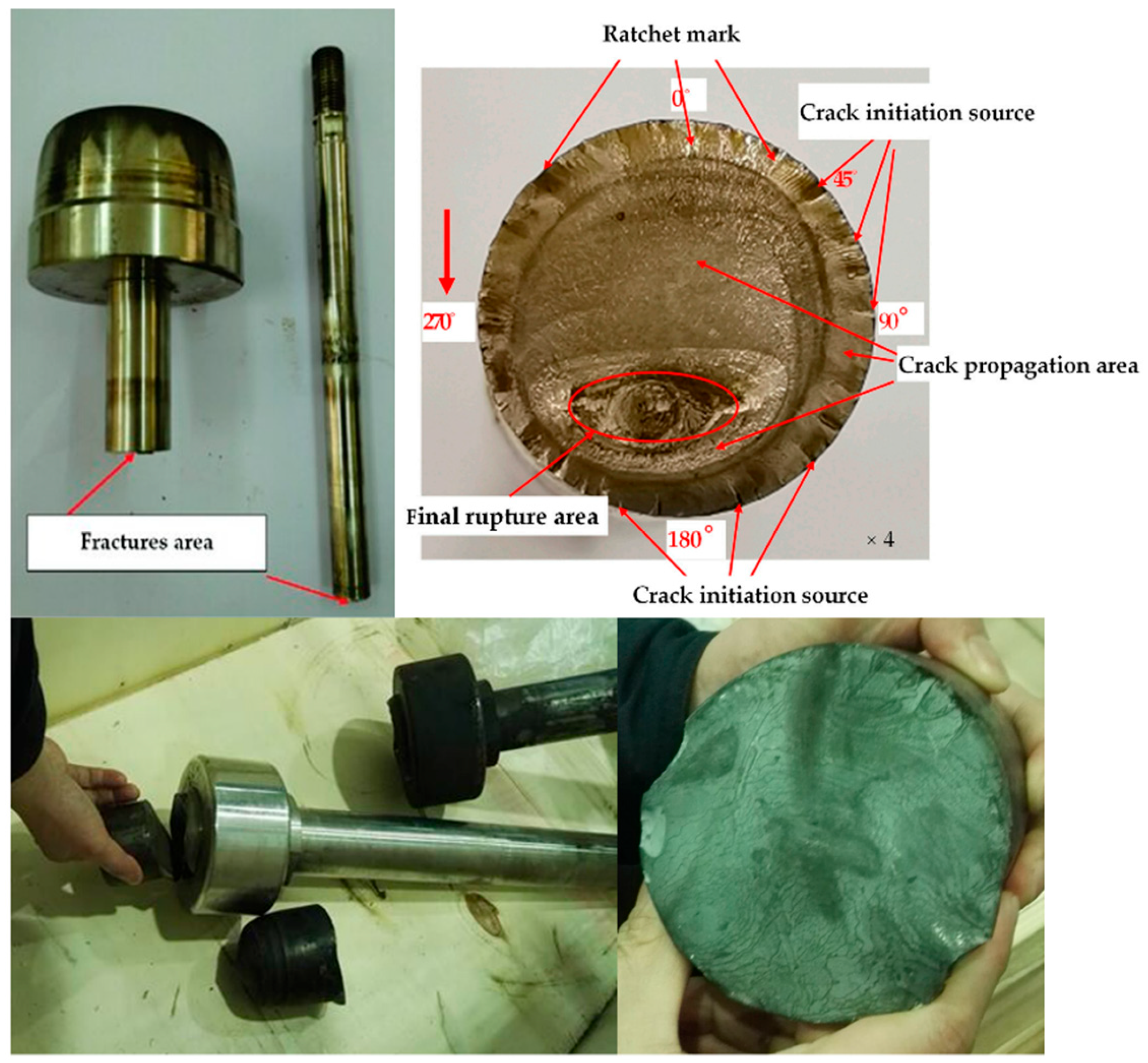
Figure 1. Damage photographs of valve plugs [4].
Machines 13 00766 g001
Figure 2. Diagram for common failure modes of valve.
Machines 13 00766 g002
Figure 3. SEM images of the fracture surface. (a) SEM observation locations of the fracture. (b) Fracture pattern of Area A at the crack source (300×). (c) Fracture pattern of B crack propagation area (800×). (d) Fracture pattern of C crack propagation area 5 (800×). (e) Fracture pattern of D final fracture area (1000×). (f) Fracture pattern of E final rupture area (1000×) [4].
Machines 13 00766 g003
Figure 4. Schematic illustration of valve plug and seat configurations under varying support and constraint conditions.
Machines 13 00766 g004
Figure 5. Control valve pressure dynamics: normal, cavitation, and flashing phases.
Machines 13 00766 g005
Table 1. Summary of flow-induced vibration failure of control valve.
Valve Plug ShapeValve Seat Flow
Direction
Identified Fluid ForcingReference
Contoured plugToricForward Acoustic mode excited by mass flow fluctuations[15]
Contoured plugToricReverse Oblique shock, jet impingement,
flow-excited acoustic resonance
[16]
Contoured plugToricReverse Jet impingement,
flow-excited acoustic resonance
[17]
Contoured plugToric with cut ForwardShock mixing processes,
separation from plug mixing processes
[18]
Slotted plugSharp edgeForwardTurbulent flow[19]
Contoured plugToricForwardSeparated flow, attached flow[20]
Disc-type plug ToricForwardShock, separation flow, attached flow[21]
Disc-type plugToricForwardUnsteady flow separation[22,23]
Contoured plugToricForwardUnsteady flow separation from the plug,
flow-excited acoustic resonance
[13,24,25,26,27,28]
ForwardVortex shedding[29]
Contoured plugToricForwardUnsteady flow[30]
Contoured plugToricForwardAsymmetric inflow at high mass flow rates[31]
Disc-type plug ToricForwardInternal flow[32]
FlatToricForwardShock-induced wall jet separation[33]
Contoured plugToricForwardUnstable flow separation, turbulent flow[34]
Contoured plugToricForwardFlow separation at diffuser outlet[35]
Contoured plugToricForwardFlow separation[36]
Disc-type plugConical ForwardWall jet separation[37]
ForwardFlow-excited acoustic resonance[38]
ForwardJet impingement[39,40]
Disc-type plugToricForwardAcoustic modes, shear layer instability[41,42]
Contoured plugToricForwardFlow-excited acoustic resonance[43]
Contoured plugToricForwardWall jet separation,
flow-excited acoustic resonance,
shear layer instability
[44,45,46,47,48,49,50,51]
Contoured plugToricForwardUnsteady flow jet detachment[52]
Disc-type plugToricForwardFlow separation from hemispherical plug[53]
Disc-type plugToricForwardJet flow[54]
Contoured plugToricForwardAcoustic-induced vibration[55]
Disc-type plugToricForwardFlow separation[56]
Contoured plugToricForwardUnsteady flow[11]
Disc-type plugToricForwardFlow separation[54,57]
Disc-type plugToricForwardWall jet separation[58]
Contoured plugToric ForwardFlow-excited acoustic resonance[59,60]
Disclaimer/Publisher’s Note: The statements, opinions and data contained in all publications are solely those of the individual author(s) and contributor(s) and not of MDPI and/or the editor(s). MDPI and/or the editor(s) disclaim responsibility for any injury to people or property resulting from any ideas, methods, instructions or products referred to in the content.