1. Introduction
With the continuous advancement of human economic society, energy demands have been growing increasingly larger. The scale of petrochemical projects employing hydrocracking technology has been consistently expanding. Correspondingly, the specifications required for reciprocating compressor units—the most critical equipment in hydrocracking installations—have also been progressively increasing. Large synchronous motors are typically employed to drive various load equipment such as reciprocating compressors. The load characteristics of such machinery exhibit continuous variations, with torque profiles generally demonstrating periodic fluctuations [
1]. Currently, in engineering practice, reciprocating compressors are increasingly adopting a stepless gas volume control system to reduce energy consumption levels and achieve cost savings [
2,
3]. This system integrates advanced control theory with electromechanical technology, enabling the entire unit to achieve maximum energy savings while maintaining high dynamic control performance [
4]. However, when driving reciprocating compressors equipped with a stepless gas volume control system, synchronous motors exhibit non-uniform oscillatory torque characteristics due to the real-time dynamic variations in compressor loading [
5,
6]. This will induce forced oscillations during the dynamic stable operation of the unit, posing potential risks to the safe and stable operation of the synchronous motor. Therefore, a dynamic characteristic analysis of the motor rotor must be conducted, as the rotor’s superior dynamic performance is essential for ensuring safe motor operation. The proper analysis of rotor system modal characteristics and critical speeds constitutes a critical aspect of both motor design and maintenance.
The dynamic characteristics of large synchronous motors (LSMs) have garnered significant research attention due to their critical role in high-power industrial applications. Recent studies primarily focus on three key aspects: the high-precision modeling of rotor-bearing systems, intelligent vibration suppression techniques, and adaptive control strategies under complex operating conditions.
Zhang et al. [
7] conducted a comprehensive rotor dynamic analysis incorporating nonlinear bearing characteristics, revealing that stiffness variations within the range of 10
8–10
9 N/m could induce significant shifts in critical speeds. Their finite element model successfully predicted vibration modes in a 10 MW synchronous motor, offering valuable insights for structural optimization. Liu et al. [
8] made substantial progress in real-time monitoring by developing a novel sliding mode observer with adaptive gain scheduling, achieving a 92% accuracy in eccentricity detection while reducing the computational load by 40% compared to conventional methods. Wang and Chen [
9] pioneered AI-enhanced predictive control by integrating deep reinforcement learning with traditional model predictive control, demonstrating a 35% improvement in transient response during sudden load changes on a 6 MW test platform.
However, current studies on modal and critical speed analyses of large synchronous motors remain relatively scarce, especially for ultra-long shaft systems (e.g., a shaft length of 5 m and a rotor diameter 6 m), for which an in-depth exploration of dynamic characteristics is still needed.
In rotating machinery systems, the predominant vibration modes include rotational, lateral (bending), and axial vibrations. Among these, rotational resonance is particularly critical as it directly impacts operational stability, especially in drivetrain systems. Therefore, for motor rotor systems, the rotational modal characteristics should be prioritized in dynamic analysis and design considerations [
10]. In modal analysis, the finite element method (FEA) has become a widely adopted approach due to its ability to handle complex geometric configurations and boundary conditions. Wang et al. [
11] investigated the rotor modal characteristics of large hydro-turbine shaft systems under varying rotational speeds using finite element methods. The study revealed a distinct speed-dependent frequency bifurcation phenomenon: the natural frequency of forward whirling modes exhibited progressive stiffening with increasing rotational speed, while backward whirling modes demonstrated corresponding softening behavior. Jung et al. [
12] performed a mechanical transient analysis on a rotor core using finite element analysis, by which the pole core structure was optimized to achieve a significant reduction in mechanical stresses within the core bridges. Du et al. [
13] conducted a modal analysis on the rotor system of a high-speed permanent magnet motor, systematically investigating the influence of bearing support stiffness, gyroscopic effects, and rotor dimensional parameters on the critical rotational speed. Wang et al. [
14] conducted a comprehensive modal analysis and critical speed determination for motor rotor shaft systems using a finite element analysis. The study successfully identified the first six-order modal shapes and corresponding natural frequencies of the rotor system. Through Campbell diagram construction, the critical speeds were precisely determined. The research notably revealed that gyroscopic moments acting on the rotor significantly influence its modal frequency characteristics. Li et al. [
15] conducted mechanical simulations on permanent magnet synchronous motor (PMSM) rotors, employing both the finite element method (FEM) and analytical approaches for comparative modal analysis with experimental validation. The study demonstrated superior agreement between the FEM results and experimental data, thereby verifying the accuracy of the finite element methodology. The calculation of natural frequencies in high-speed motors using the three-dimensional finite element method, coupled with the investigation of support stiffness effects on their dynamic characteristics, has emerged as a critical approach for vibration suppression in motor rotor systems [
16]. Hong et al. [
17] conducted numerical simulations to determine the natural frequencies of high-speed motors and performed a comparative analysis with experimental results. The demonstrated close agreement between simulation and experimental data effectively validated the accuracy of the computational methodology employed in the study. Current research in electromechanical dynamics predominantly focuses on small to medium power-rated high-speed rigid rotors, while studies addressing the dynamic characteristics and factors influencing flexible rotors in large-scale synchronous motors remain comparatively scarce. Compared to small- and medium-sized motors, large synchronous motors exhibit lower rotational speeds and feature rotor lengths exceeding their diameters. These machines predominantly employ flexible rotors that must traverse the first critical speed during their operation and operate between higher-order critical speeds. This operational characteristic poses significant challenges to the dynamic design of large synchronous motors, necessitating a precise dynamic analysis of the rotor system to ensure operational stability and reliability.
This study focuses on a large-scale low-speed synchronous motor (7800 kW, 18-pole, and 300 rpm). Initially, modal analyses are conducted on the rotor system under both bladed and non-bladed configurations to determine their respective natural frequencies. Subsequently, critical speed calculations are performed for the centralized-mass rotor system to evaluate the rationality of operational speed selection. Experimental validation is further conducted using a physical motor prototype to verify the model accuracy. The research outcomes provide crucial theoretical foundations and technical support for ensuring the stable rotor operation of large electrical machinery under complex working conditions.
2. Finite Element Model for Rotor System
In rotor dynamics analysis utilizing finite element analysis software, the rational simplification of three-dimensional rotor models demonstrates substantial engineering significance. The structural complexity of rotor systems often leads to prohibitive computational costs and time expenditures when performing analyses using full three-dimensional models. In dynamic characteristic analyses of rotating machinery systems, the dynamic performance is predominantly governed by three intrinsic mechanical properties: rotational inertia, elastic modulus, and damping characteristics. Consequently, employing simplified modeling methodologies—such as representing rotor components through beam elements, lumped mass points, or axisymmetric models—can effectively reduce computational complexity by minimizing the system’s degrees of freedom. This strategic simplification enables substantial improvements in computational efficiency while maintaining essential dynamic characteristics for engineering analysis. This approach not only effectively captures the primary dynamic characteristics of rotor systems—including critical speeds, vibration modes, and unbalance responses—but also streamlines the model by omitting non-essential details, thereby enabling a more focused analysis on the global dynamic behavior of the rotating machinery system.
2.1. Simplification Techniques for Modal Analysis of Three-Dimensional Rotor Models
The modal characteristics of a rotor system, including natural frequencies, mode shapes, and damping ratios, are collectively determined by multiple interacting factors. These principally encompass the rotor’s mass distribution, geometric configuration, material properties, and moment of inertia—all of which directly govern its stiffness and inertial characteristics. External loads and excitation may induce vibrations but exhibit minimal influence on natural frequencies; system boundary conditions (such as fixed ends or elastic supports) primarily determine the modal distribution and characteristic mode shapes. Through the rational adjustment of these parameters, the modal characteristics of the rotor system can be optimized, thereby enhancing its dynamic performance, operational safety, and operational efficiency.
The dynamic analysis of large synchronous motors mainly adopts geometric symmetry (sector model), concentrated mass approximation, and linearized bearing stiffness to reduce computational costs and retains fine meshes in key areas (such as air gaps) to ensure the accuracy of the model [
18,
19].
For the large synchronous motor discussed in this study, the structural complexity of the rotor system can be effectively simplified by omitting the fillet features on the rotor core and disregarding the blade-fastening bolt holes in the rotor spider assembly. The magnetic pole core can be simplified into lumped mass points through the mass lumping technique to effectively reduce model complexity.
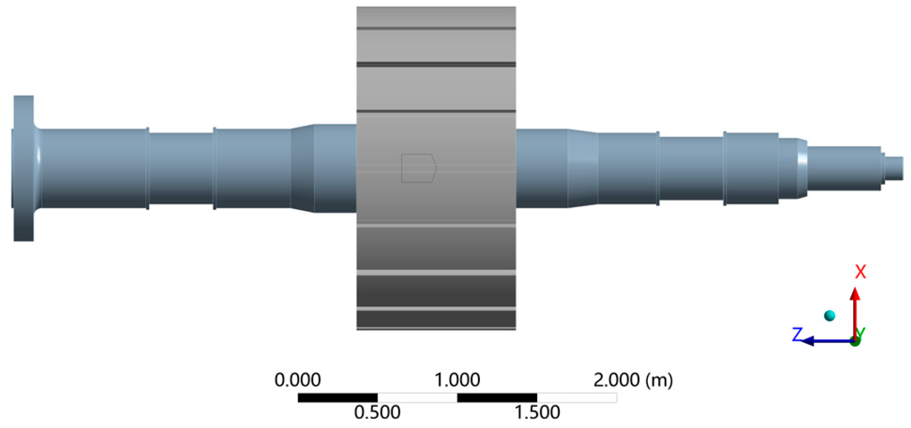
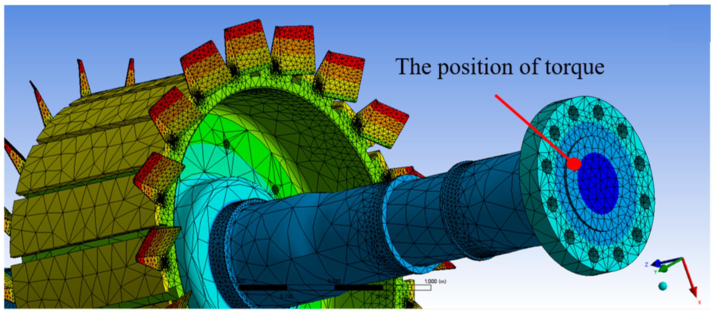
The rotor assembly of synchronous motors primarily consists of the following components: shaft body, rotor spider, field pole windings, pole cores, cooling fans, exciter armature, exciter cooling fan, and rotating rectifier assembly. The excitation system, owing to its excessive structural complexity and minimal impact on the overall mechanical framework, was simplified in the simulation analysis through substitution with a mass element incorporating rotational inertia properties. The rotor assembly configuration of the synchronous motor is illustrated in
Figure 1.
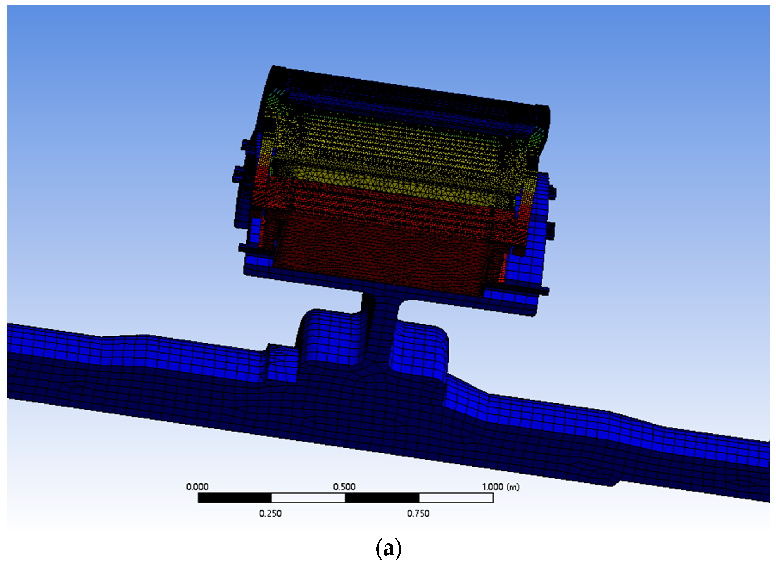
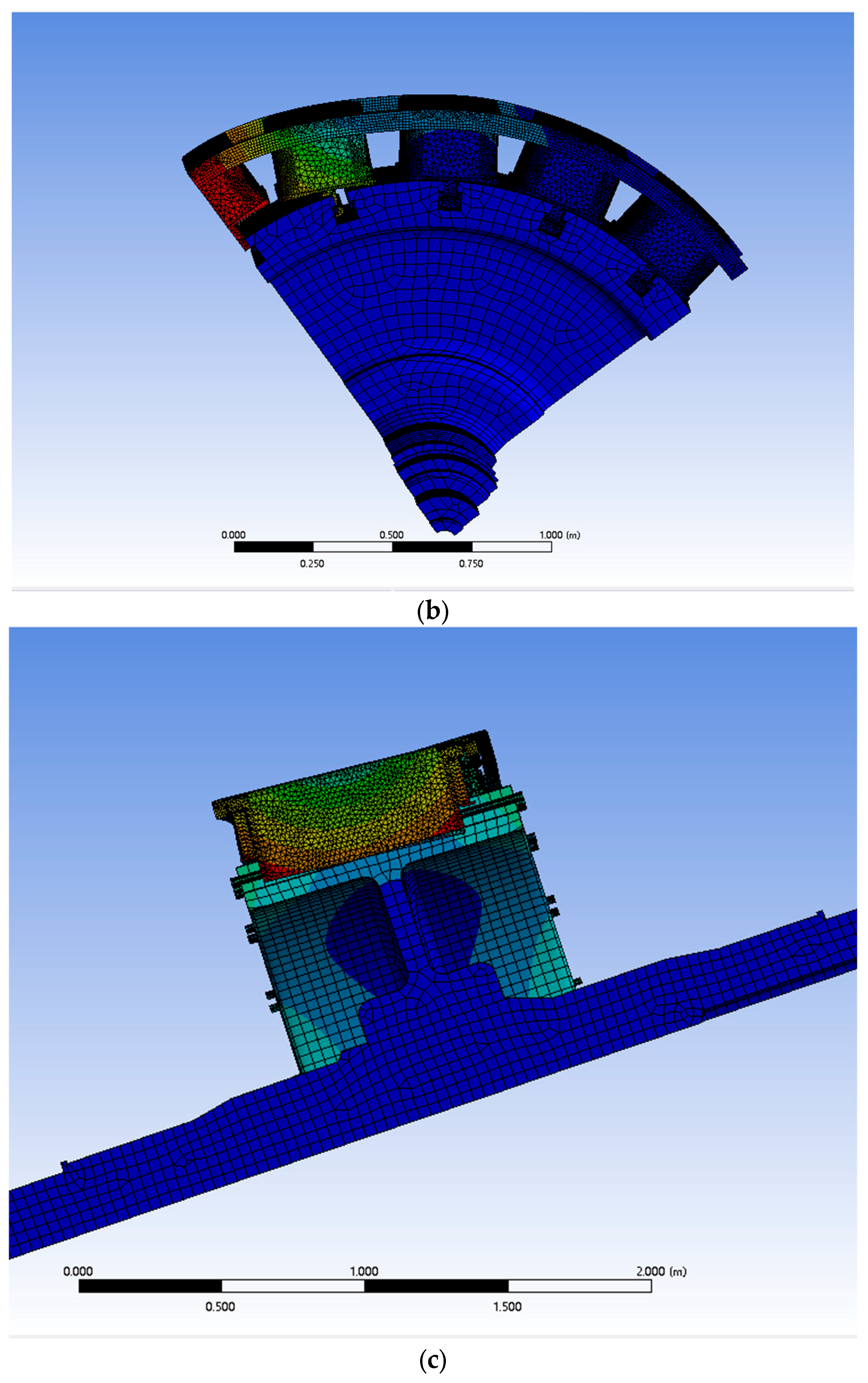
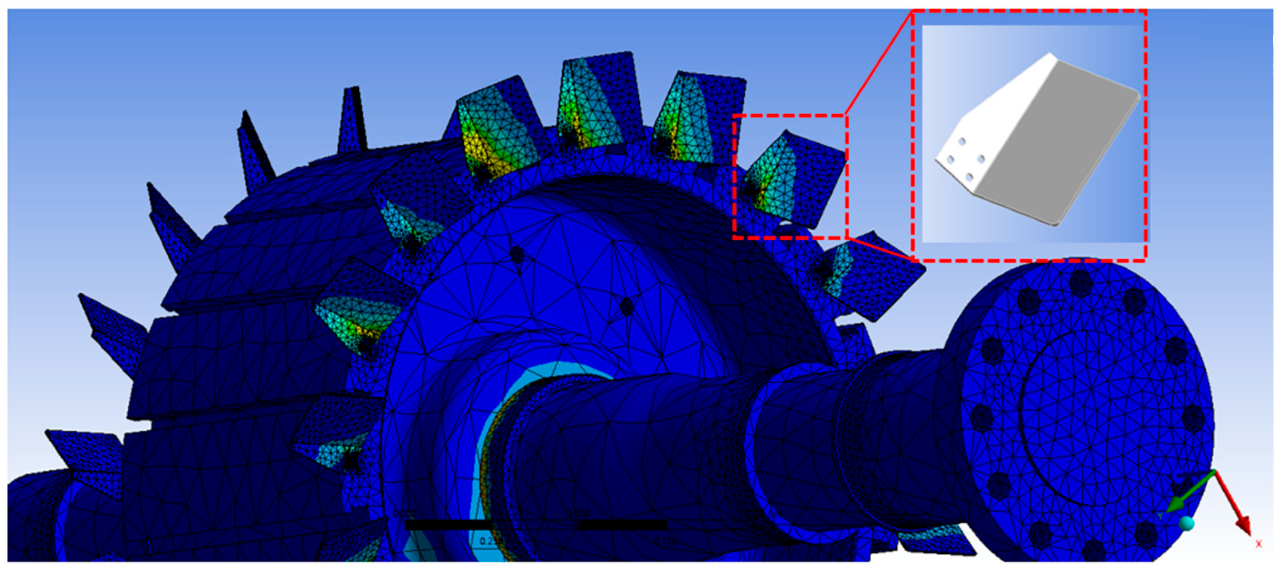
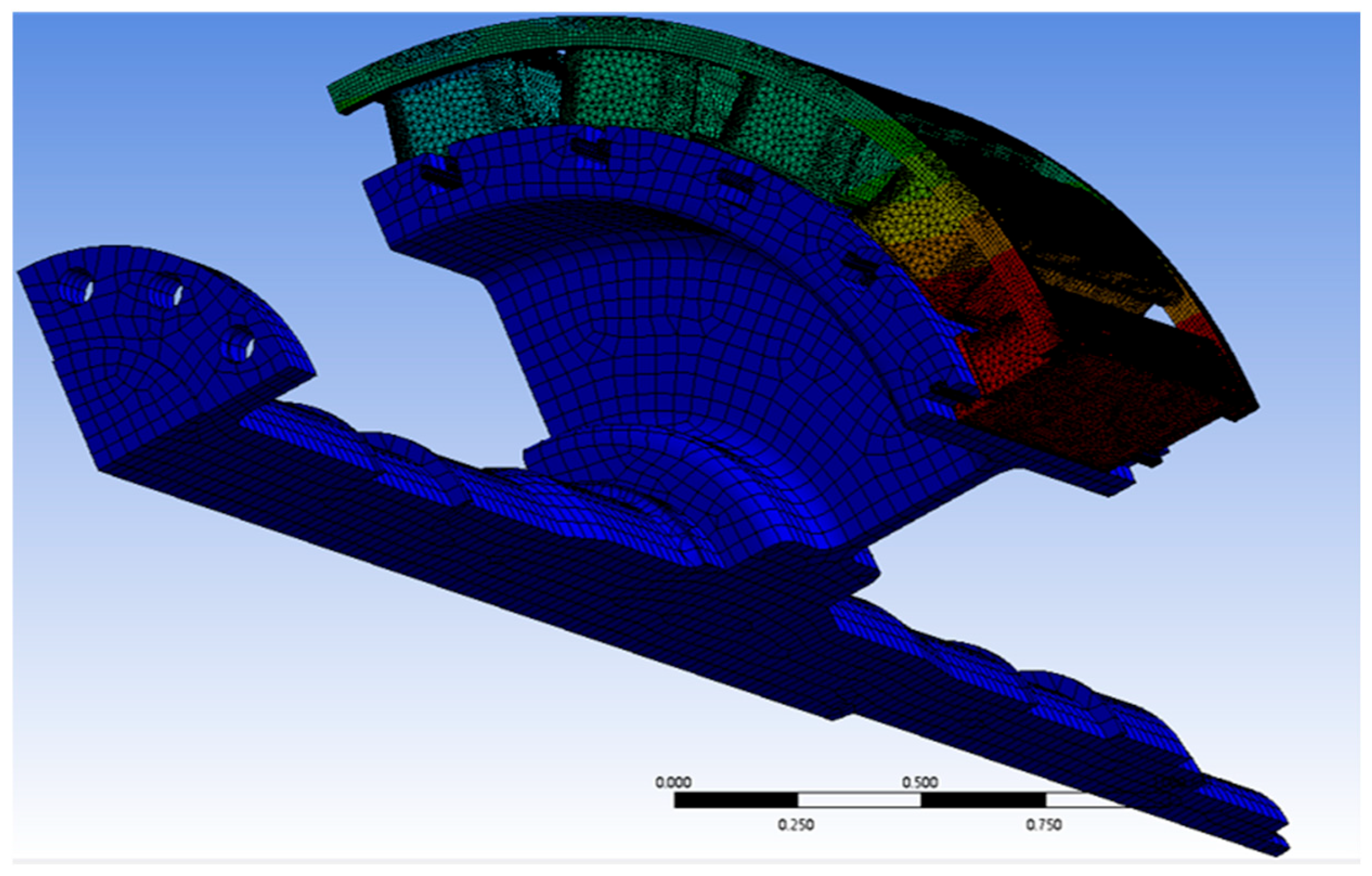
During modal analysis, while both the global deformation of the rotor assembly and local deformation of fan blades must be considered, the inherent complexity of the full-scale model presents challenges. The fixed orientation of fan blades creates geometric asymmetry, and numerous intricate components within the magnetic pole core relative to the overall structure complicate direct simulation. To address this, the analysis was segmented into two components: the fan blade assembly and the magnetic core assembly. The magnetic core subassembly, when analyzed independently, permits the implementation of quarter-symmetry for the simplification of computational efficiency. As illustrated in
Figure 2, only the magnetic core segment requires a quarter-symmetry simplification for efficient analysis.
2.2. Simplification Methods for Critical Speed
The analysis of three-dimensional rotor modeling critical speed, a paramount indicator in rotor system dynamics, is dictated by both intrinsic rotor characteristics and external supporting conditions. The rotor’s mass distribution, geometric configuration, material properties, and moment of inertia constitute critical influencing factors. The concentrated mass distribution generally elevates the critical speed, whereas rotors with higher length-to-diameter ratios or denser materials tend to exhibit lower critical speeds. Boundary conditions (including fixed-end, free-end, or elastic supports) significantly affect vibrational modes and natural frequencies, thereby modifying critical speed distribution patterns.
For the highly intricate rotor system under investigation, the spindle and rotor support brackets constitute the most substantial mass proportion within the assembly and serve as critical components. In the critical speed analysis, the bearing parameters were selected based on established engineering practice: a damping coefficient of 2 × 10
6 N·s/m and a stiffness value of 1 × 10
8 N/m were assigned to the bearing supports. We retained these essential elements while implementing strategic simplifications to enhance computational efficiency. The rotor geometry was simplified by neglecting minor features such as fillets and small apertures to reduce geometric complexity. Furthermore, the magnetic pole cores were abstracted as concentrated mass points through mass lumping techniques, thereby achieving effective model simplification while preserving mechanical integrity. This study employs a simplified modeling approach that preserves both mass and moment of inertia equivalence before and after the simplification. The methodology retains only critical components of the rotor system, specifically the main shaft and rotor bracket assembly, while representing secondary elements such as wedge keys, magnetic pole cores, and fixing blocks as discrete mass points.
Table 1 details the parametric specifications of the simplified entities. Components with negligible contributions to the overall mass or moment of inertia (typically below the 0.5% threshold) were systematically excluded from the model, as their exclusion was determined to exhibit a minimal impact on the comprehensive dynamic analysis.
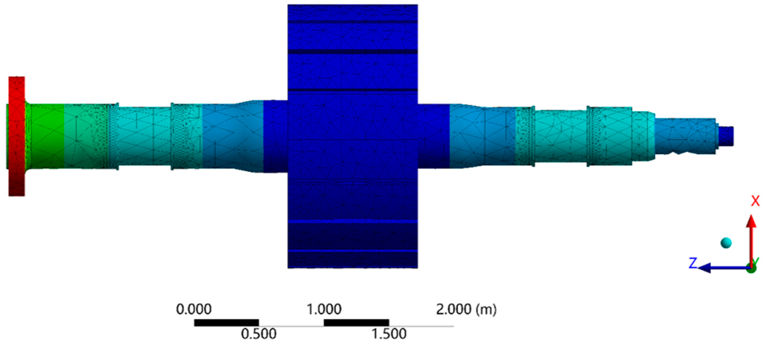
The streamlined model architecture is schematically presented in
Figure 3.
5. Critical Rotational Speed Analysis of Electric Motor Rotors
In rotor dynamics analysis, the critical speed refers to the rotational velocity at which the operating frequency of a rotor system coincides with its natural frequency, holding significant engineering implications. Through critical speed identification, engineers can prevent rotor systems from operating near or at these hazardous rotational velocities, thereby maintaining operational safety by steering clear of resonance zones. Furthermore, critical speed analysis enables a comprehensive evaluation of rotor system stability. By optimizing design parameters such as bearing stiffness and rotor geometry, engineers can strategically modify the distribution of critical speeds, effectively enhancing the rotor’s dynamic characteristics and operational reliability.
The Campbell diagram plays a pivotal role in analyzing the critical speeds of rotor systems by graphically presenting the variation in natural frequencies with rotational speed, superimposed with excitation frequency lines to visually identify critical speed positions. For synchronous motors experiencing rotational resonance, the primary excitation source stems from mass unbalance. Accordingly, the excitation frequency line is selected as the 1× rotational frequency line. The rotational speed range of 0–300 rpm was divided into four intervals, with the first 15 modal frequencies measured during each test. The Campbell diagram from the numerical simulation result is illustrated in
Figure 10.
At a rotational speed of 300 rpm, the 15th-order vibration mode is illustrated in
Figure 11. The actual natural frequency of this mode measures 298 Hz (note: the software artifact forced the value to be displayed as 0 Hz, which does not reflect the physical reality). This confirms that the excitation frequency line and the natural frequency curve of Mode 15 do not intersect in practical operation. Consequently, only the first five critical speed points are genuine, with the sixth point’s rotational speed significantly exceeding the rated speed of the large synchronous motor. This configuration ensures all critical speeds remain outside the motor’s normal operational range.
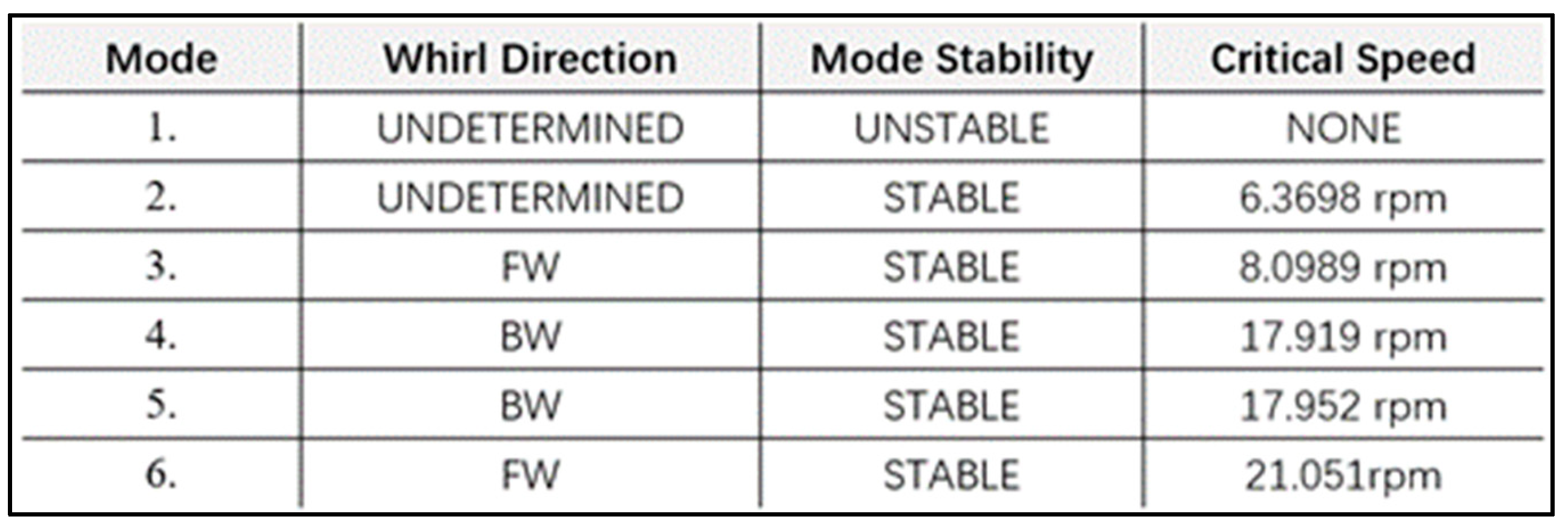
The actual critical speed analysis reveals five distinct critical speed points, as illustrated in
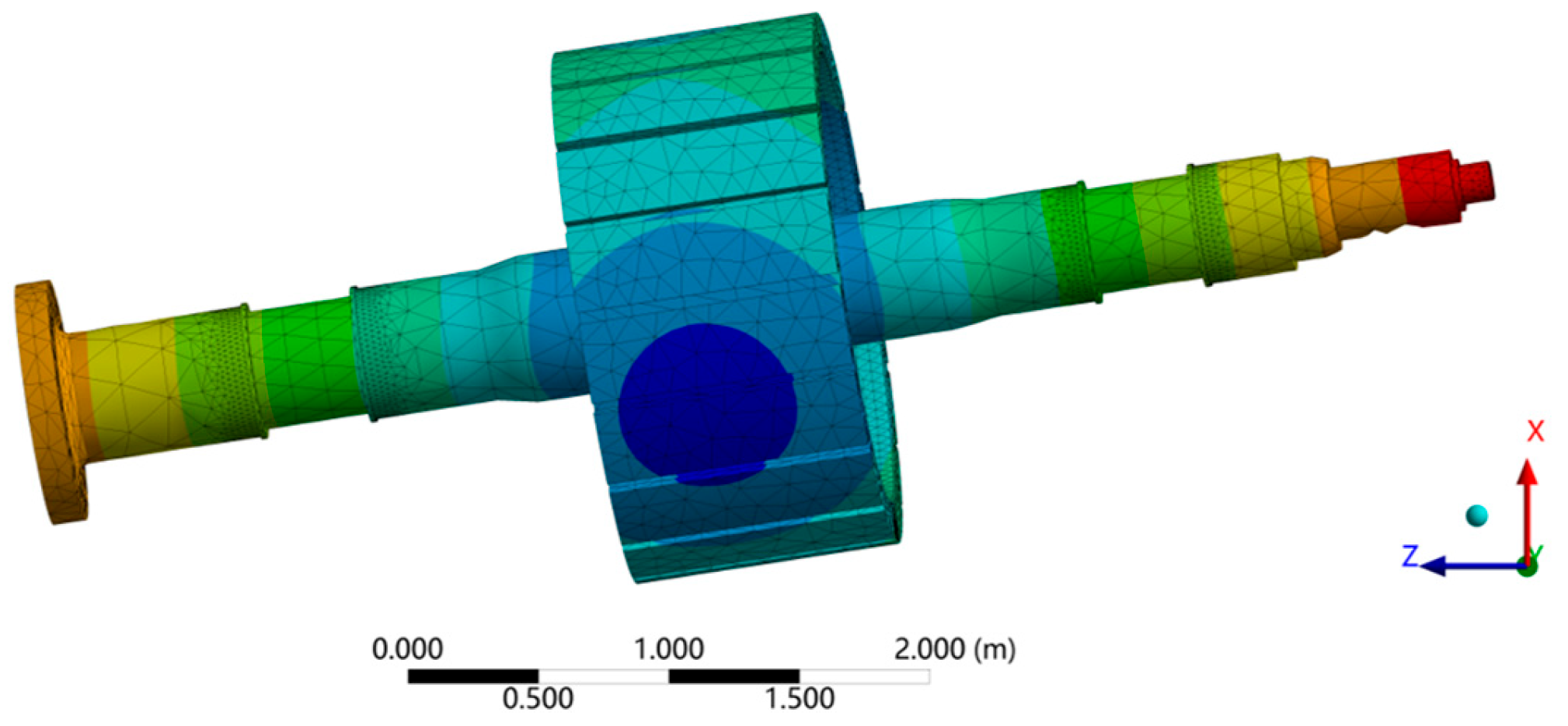
Figure 12, where FW and BW denote forward whirling and backward whirling, respectively. The critical speed analysis reveals two distinct whirling modes: forward whirling and backward whirling. Forward whirling, characterized by vibration orbits that rotate in the same direction as the shaft rotation, represents the primary resonance phenomenon induced by mass unbalance in rotor systems. Consequently, when analyzing rotational resonance behavior, only forward whirling requires consideration as the dominant mode. Therefore, only the two forward whirling modes (the third and sixth orders) require consideration. The third-order natural frequency corresponds to a composite bending–translational mode shape (
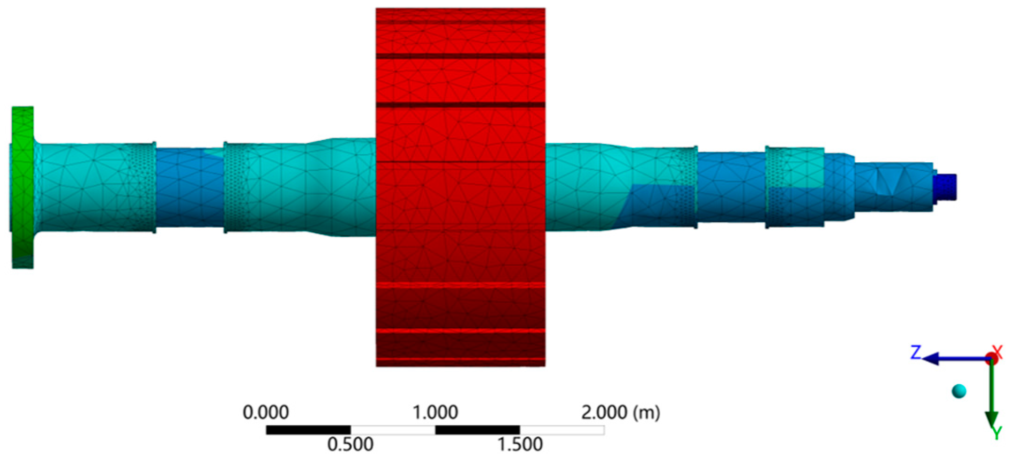
Figure 13), which fundamentally results from structural deformation rather than rotational effects. In contrast, the sixth-order natural frequency manifests as a rotational mode shape (
Figure 14), representing the genuine critical speed that must be avoided during operational conditions. The calculated critical speed was determined to be 21.051 rpm. Notably, this value is substantially lower than the rated operating speed of 300 rpm for this large-scale synchronous motor. This significant margin ensures that the motor maintains stable and continuous operations throughout its designed speed range.
6. Modal Testing of Motor Rotor Systems
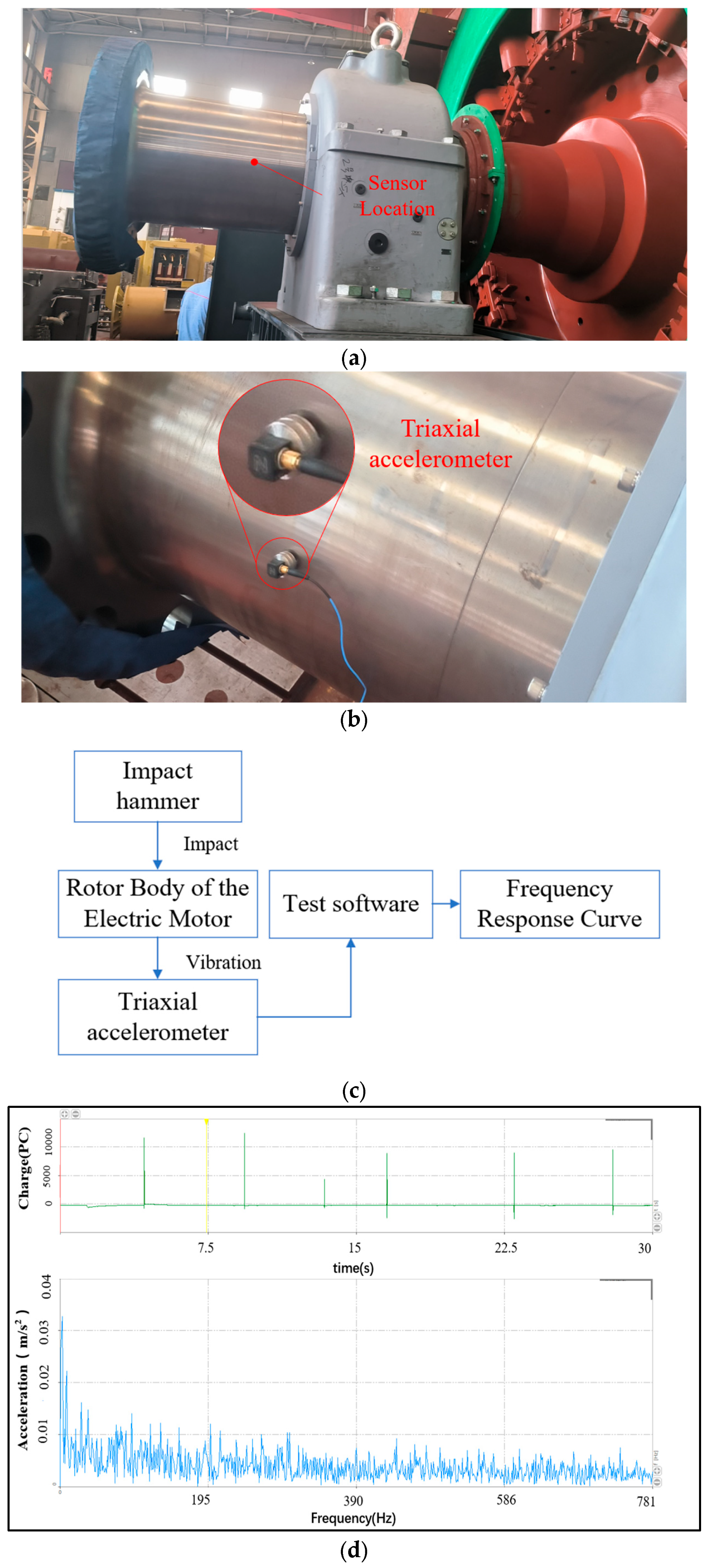
Based on the aforementioned theoretical analysis, this study conducted impact hammer modal testing on the actual motor rotor. The experimental setup employed a fully assembled large synchronous motor, complete with bearing support structures, ensuring close alignment with the boundary conditions specified in the simulation analysis. As illustrated in
Figure 15, the measurement configuration includes the overall motor rotor assembly (
Figure 15a) and the selection of measurement points, with the output flange end being designated as the primary measurement location. A triaxial acceleration sensor was employed to capture vibration responses (
Figure 15b). The impact excitation was applied adjacent to the measurement point due to the substantial mass of the motor rotor, where insufficient impact energy or excessive distance from the excitation source could result in undetectable vibration signals. Impact directions were systematically applied along both axial and radial orientations to ensure comprehensive modal parameter acquisition.
Figure 15c shows a flowchart of the experimental procedure, and the output results of the testing process are presented in
Figure 15d.
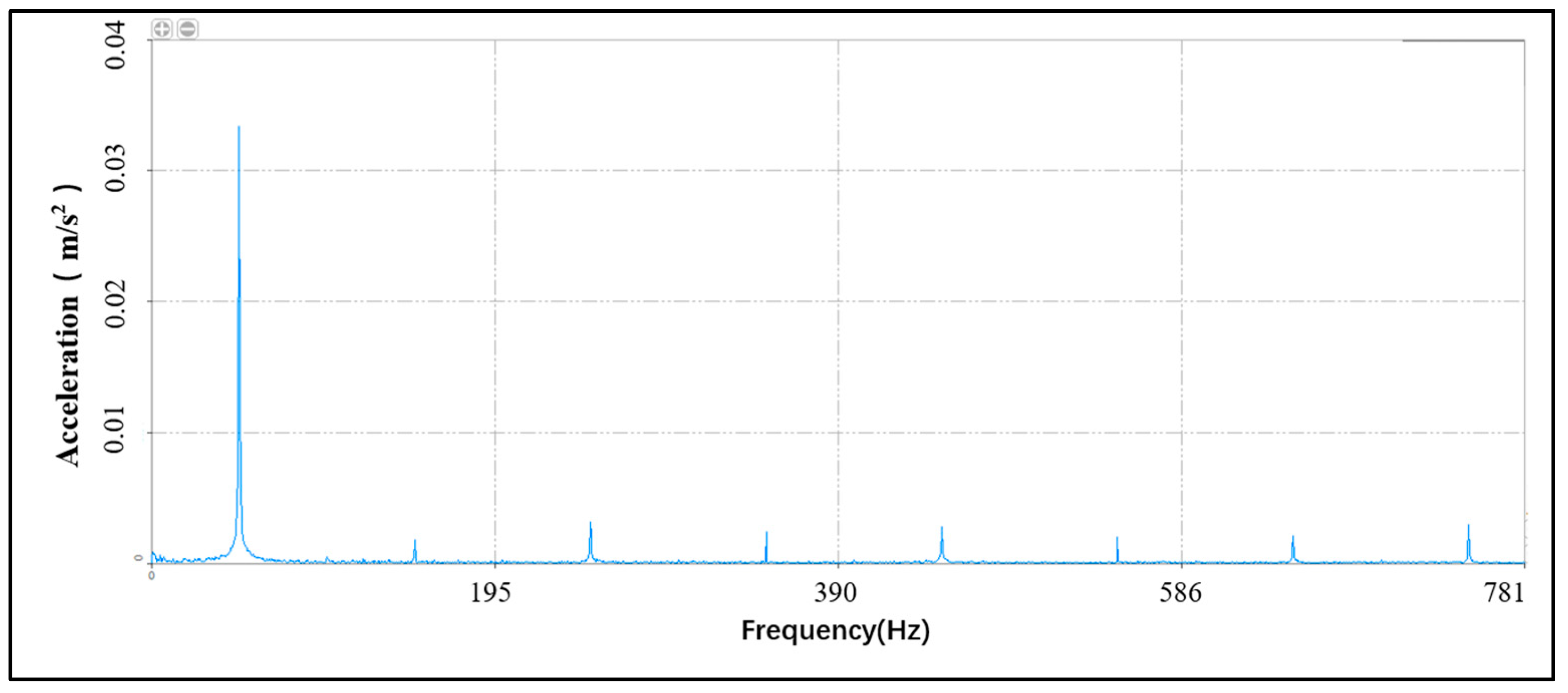
As illustrated in
Figure 16, the natural frequencies observed in radial impact testing consistently manifest as odd harmonics of the 50 Hz power supply frequency (i.e., 50 Hz, 150 Hz, 250 Hz, etc.). This phenomenon contradicts conventional mechanical excitation patterns, as typical vibration spectra should not contain odd multiples of line frequency. Two plausible mechanisms are proposed for this anomaly:
Power Supply Interference: During testing on the intact motor assembly, the fundamental power frequency and its harmonics may infiltrate vibration sensors through electromagnetic field coupling or electrical circuit coupling, thereby contaminating measurement signals with odd harmonic components;
Stator–Rotor Electromechanical Interaction: The complete motor configuration includes both stator and rotor components. Radial impacts may induce relative displacement between these electromagnetic subsystems, potentially generating stator–rotor coupling effects. This electromechanical interaction could preferentially excite odd harmonic frequencies in the system’s dynamic response.
Figure 16.
Frequency response curve under radial impact.
Figure 16.
Frequency response curve under radial impact.
This frequency characteristic suggests either measurement signal contamination by power line interference or the emergence of nonlinear electromagnetic–structural coupling phenomena during transient impact events. Further isolation testing (electrically decoupled configuration) and modal analyses are recommended to distinguish between these mechanisms.
Figure 17 presents the modal test results under axial impact loading. Due to the model’s complexity, the simulation analysis was performed by dividing the system into two separate components—the magnetic pole core assembly and the fan blade assembly—to investigate their individual dynamic responses. In contrast, experimental testing was conducted on the fully assembled rotor system, precluding the isolated component evaluation. For comparative validation, we selected the magnetic pole core simulation results from
Section 3.2 for analysis, as this component demonstrates greater influence on the overall system dynamics.
The peak values in
Figure 17 correspond to the motor’s natural frequencies, which can be precisely determined using the cursor positioning function in the analysis software to identify and record each resonant peak’s exact frequency value. The results presented in
Table 4 indicate that the natural frequencies obtained through the simulation exhibit relatively minor discrepancies compared with experimental measurements, demonstrating the reliability of the simulation model. Notably, certain experimentally observed frequencies (e.g., 207 Hz, 308 Hz, and 400 Hz) not corresponding to the simulation results were identified as even-order harmonics of the power supply frequency, potentially attributable to rotor–stator coupling effects or power supply frequency interference phenomena.
