Article

Collision Avoidance of Driving Robotic Vehicles Based on Model Predictive Control with Improved APF

Key Laboratory of Mechanism Theory and Equipment Design of Ministry of Education, Tianjin University, Tianjin 300350, China
*
Author to whom correspondence should be addressed.
Machines 2025, 13(8), 696; https://doi.org/10.3390/machines13080696
Submission received: 16 July 2025 / Revised: 31 July 2025 / Accepted: 4 August 2025 / Published: 6 August 2025

Abstract

To enhance road-testing safety for autonomous driving robotic vehicles (ADRVs), collision avoidance with sudden obstacles is essential during testing processes. This paper proposes an upper-level collision avoidance strategy integrating model predictive control (MPC) and improved artificial potential field (APF). The kinematic model of the driving robot is established, and a vehicle dynamics model considering road curvature is used as the foundation for vehicle control. The improved APF constraints are constructed. The boundary constraint uses a three-circle vehicle shape suitable for roads with arbitrary curvatures. A unified obstacle potential field constraint is designed for static/dynamic obstacles to generate collision-free trajectories. An auxiliary attractive potential field is designed to ensure stable trajectory recovery after obstacle avoidance completion. A multi-objective MPC framework coupled with artificial potential fields is designed to achieve obstacle avoidance and trajectory tracking while ensuring accuracy, comfort, and environmental constraints. Results from Carsim-Simulink and semi-physical experiments validate that the proposed strategy effectively avoids various obstacles under different road conditions while maintaining reference trajectory tracking.

1. Introduction

For robot-controlled vehicles to complete road tests, they must achieve precise and stable trajectory tracking while safely and efficiently handling emergencies, including complex scenarios with road obstacles and multi-vehicle coordination [1,2]. The decision-making module must quickly generate an obstacle avoidance path when necessary. The vehicle should then seamlessly resume its original trajectory after completing the maneuver to maintain mission continuity and integrity. Therefore, developing an intelligent obstacle avoidance strategy that can both ensure safety and maintain test efficiency has important theoretical significance and practical application value.
The field of autonomous vehicle path planning has witnessed rapid development, encompassing approaches from hierarchical multi-agent coordination systems [3] to individual vehicle decision-making algorithms. Various obstacle avoidance algorithms have found extensive application in domains like self-driving cars and unmanned aerial vehicles (UAVs). For autonomous driving robots controlling vehicles to perform obstacle avoidance tasks, the fundamental challenges such as real-time trajectory tracking, collision avoidance, and dynamic path replanning are conceptually analogous to those faced by autonomous vehicles [4]. Therefore, the development of upper-level collision avoidance algorithms for ADRV systems can refer to the avoidance algorithm of autonomous vehicles.
For autonomous driving applications, the main aim of path planning is to achieve safe, collision-free, and feasible trajectories. Currently, mainstream obstacle avoidance algorithms mainly include graph search methods, sampling methods, and optimization methods [5,6,7]. As a classical heuristic graph search algorithm, A* algorithm [8,9] identifies optimal paths by discretizing maps into grids and employing heuristic functions for cost estimation. However, conventional A* algorithms are primarily designed for global path planning in static environments and exhibit significant limitations when addressing dynamic obstacles [10]. In contrast with map-based search approaches, sampling-based planning algorithms eliminate the requirement for precise environmental modeling. Methods such as Probabilistic Roadmap (PRM) [11,12] and the Rapidly exploring Random Tree (RRT) [13] explore the configuration space through random sampling, demonstrating superior adaptability to dynamic conditions. For PRM, traditional PRM implementations face challenges including lack of directional guidance in sampling and inefficient search performance. In [14], a spatial axis-guided pseudo-random sampling strategy and optimized collision detection method are demonstrated to enhance construction speed and planning efficiency for vehicular applications. The RRT algorithm randomly explores the environment by creating nodes and a search tree. However, this randomness hinders the algorithm’s ability to guarantee high-quality paths [15]. While these methods demonstrate effectiveness in global path planning scenarios, they encounter limitations in real-time vehicle obstacle avoidance due to computational delays and requirements for complete environmental reconstruction.
The artificial potential field (APF) method has drawn considerable attention for its computational simplicity and real-time performance characteristics. This approach guides vehicle motion along the gradient descent direction of potential fields by constructing attractive fields toward target points and repulsive fields around obstacles [16,17,18]. However, conventional APF methods face inherent limitations like local minima, inability to reach the goal, and oscillation phenomena. Researchers have proposed various improvement strategies to address these challenges. In [19], an APF method based on collision regions and corresponding safety distances is introduced to adapt to dynamic environments, successfully generating safe paths in simulated traffic scenarios. A different approach uses a sub-goal path attraction potential field. This field is based on obstacle and path information, and includes a velocity repulsive potential field (RPF) to account for relative velocities. The improved APF boosts adaptability to dynamic obstacles and allows coordinated control of path tracking and local obstacle avoidance, though vehicle dynamics characteristics are not addressed [20]. The paper [21] has proposed an improved APF with an enhanced attractive potential field to address the local minima issue; however, this approach is only suitable for static obstacles. In [22], for UAV path planning applications, an improved rotational potential field is developed that effectively resolves local minima and oscillation issues. Nevertheless, existing APF methods in the literature predominantly apply to straight-line paths, assuming obstacle avoidance scenarios occur exclusively on linear segments. These approaches lack generalizability across different obstacle types and varying road conditions. Additionally, most potential field designs rely primarily on relative distance metrics. Therefore, there exists a critical need to establish a unified potential field model that is applicable across diverse road conditions and scenarios.
Model predictive control (MPC), an optimization-based control approach, has acquired widespread attention in path planning applications because of its systematic capability to handle multi-constraint and multi-objective optimization problems. MPC enables predictive obstacle avoidance trajectory planning by solving optimal control sequences within finite time horizons [23,24,25,26]. Traditional approaches for trajectory planning and tracking typically involve separate modules: a local trajectory planner designs appropriate trajectories, followed by a tracking controller that executes the planned path. For instance, reference [27] employs an improved APF method that considers vehicle dynamics constraints and incorporates adjustment factors to pre-plan feasible high-speed overtaking paths, subsequently utilizing MPC for tracking control. However, this approach is restricted to known scenarios and control applications. In recent years, the idea of integrated control has been developed, and the joint application of APF and MPC in vehicle dynamics and obstacle avoidance has been widely studied. By incorporating obstacle penalties into MPC cost functions, optimal control inputs can be generated that simultaneously address path planning and tracking control objectives [28]. The paper [29] has developed artificial risk potential field modeling that considers traffic environments and driving styles, integrating these elements into MPC design processes to optimize both trajectory and control outputs. In [30], a new APF method creates banana-shaped 3D virtual obstacles for curved roads. These help generate safe, comfortable, and feasible avoidance paths. An event-triggered model predictive control (EMPC) has been developed in [31]. It uses adaptive artificial potential fields and includes special obstacle avoidance constraints and robust terminal control to lower computational costs while maintaining effectiveness. However, considering the complexity of the vehicle–road system and the variability of environmental conditions, the obstacle avoidance problem of different obstacles in different road environments still needs attention. Furthermore, the multi-constraint optimization problems in MPC strategies present ongoing challenges for practical implementation.
Motivated by these considerations, this paper proposes an upper-level obstacle avoidance algorithm integrating path planning and tracking control for the ADRV. The proposed approach achieves unified path planning and trajectory tracking control through the integration of nonlinear MPC with environment-constrained potential field methods. The main contributions of this work are as follows:
(1)
This work proposes a unified universal potential field constraint framework that significantly advances current APF methodologies. The proposed generalized potential field model differs from existing APF methods. It considers threat levels and adapts to various obstacles and road types, unlike methods designed for specific obstacle types or straight paths. This approach significantly improves safety and adaptability compared to conventional distance-based potential field designs.
(2)
An environment-adaptive potential field design in the Frenet coordinate system is developed to address the limitations of existing methods in complex road scenarios. The coordinate-transformation-based framework ensures consistent performance across arbitrary road curvatures and features a novel auxiliary attractive potential field mechanism. This design guarantees stable trajectory recovery after obstacle avoidance maneuvers, solving the critical problem of seamless return to original paths.
(3)
An integrated MPC-APF optimization framework is established that unifies path planning and trajectory tracking in a single-stage approach. This unified optimization simultaneously handles path planning and trajectory tracking while reducing computational complexity. The framework incorporates multi-objective optimization considering comfort, safety, and control smoothness, providing superior performance compared to traditional two-stage planning and tracking approaches.
The remainder of this paper is organized as follows. In Section 2, the mechanical structure and kinematic model of the autonomous robot are introduced, and the vehicle error dynamics model considering the influence of road curvature is established. Section 3 presents the discretized vehicle model, introduces the moving obstacle model, and details the design of a multi-objective trajectory planner integrated with improved artificial potential field constraints. Section 4 evaluates the algorithm’s performance in obstacle avoidance scenarios using simulation and hardware-in-the-loop (HIL) validation with Opal-RT systems. The paper concludes in Section 5 with summary remarks and directions for future investigation.

2. Modeling of Driving Robot and Vehicle

The kinematic model of the driving robot is constructed in this section based on its mechanical structure, providing the groundwork for control system design. The vehicle dynamics modeling is also investigated.

2.1. Autonomous Driving Robot

The autonomous driving robot comprises three primary components: the steering robot, the pedal robot, and the gear shifting robot [32,33]. This study examines robot-controlled automatic transmission vehicles avoiding obstacles. Figure 1 shows the mechanical layouts of the steering and pedal units, which were structurally evaluated. For the pedal robot, the pedal robot comprises two main components: an accelerator actuator and a brake actuator. Both actuators employ a similar structural design, featuring a servo motor, a series of transmission linkages, and a clamping mechanism for pedal engagement. The steering robot, on the other hand, integrates a gear transmission system, a steering wheel clamp, and a servo motor to enable precise angular control.
The vehicle’s steering mechanism is modeled using simplified conditions that exclude steering shaft damping and power assistance influences. The kinematics of the steering robot are analyzed as shown in Equation (1):
θ r o b o t = i s i g δ f
where ig denotes the linear proportionality coefficient between the front-wheel steering angle and steering wheel angle, is indicates the transmission ratio between the steering wheel and steering mechanism, and δf represents the front-wheel steering angle.
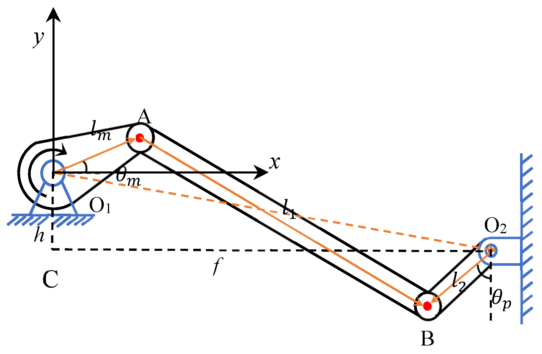
The driving robotic leg architecture undergoes reasonable simplification for analytical purposes. During the modeling, potential spatial displacement deviations at the ball joint connections of the robotic leg are considered. The actuator’s motion is constrained to a 2D plane for analysis, shown in Figure 2. This simplification relies on empirical engineering judgment: under normal operation, spatial offsets from ball joint connections have a relatively limited impact on overall control accuracy, allowing reasonable simplification while maintaining basic model accuracy. According to these principles, the kinematic representation of the driving robotic leg is formulated as follows:
f A cos ( θ m ) f B sin ( θ m ) f C = 0 f A = f l 2 sin ( θ p ) f B = h + l 2 cos ( θ p ) f C = A 2 + B 2 + l m 2 l 1 2 2 l m
Based on above Equation (2), the pedal angle θm is a function of f(A), f(B), and f(C). Each of f(A), f(B), and f(C) is a function of the driving angle θp. Since all other relevant parameters are known and measurable, the pedal angle θp can be formulated as a function of the driving angle θm, as given by Equation (3):
θ m = f A , B , C θ p

2.2. Vehicle Dynamics Model

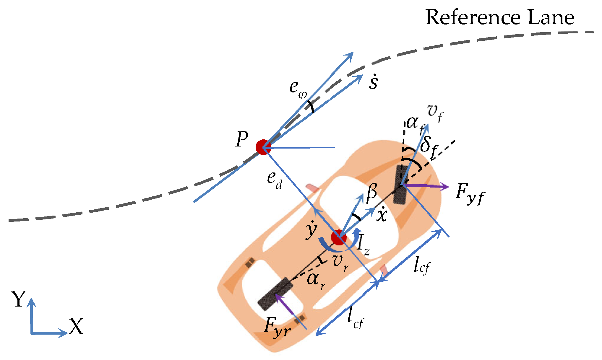
Complex vehicle models impose significant computational burdens, whereas simplified kinematic models lead to understeer and are inapplicable at medium-to-high speeds. This section introduces a vehicle error dynamics model [34,35], which has been widely used in trajectory tracking control. As illustrated in Figure 3, point P represents the closest point on the road centerline to the vehicle’s midpoint, with ed showing the lateral distance between point P and the vehicle. The heading error eφ corresponds to the angle between the vehicle’s longitudinal velocity and the velocity orientation of the closest point, thus establishing a basis for dynamic tracking error quantification.
e ˙ φ = φ k ref s ˙ e ˙ d = x ˙ sin ( e φ ) + y ˙ cos ( e φ ) s ˙ = x ˙ cos ( e φ ) + y ˙ sin ( e φ ) 1 k r e f e d
where L represents the vehicle’s wheelbase. x ˙ and y ˙ represent the longitudinal and lateral velocities in the body coordinate system, respectively. s ˙ indicates the longitudinal velocity at the nearest point to the vehicle. kref is the curvature of the reference trajectory.
Considering tire lateral and yaw dynamic characteristics, a small-angle sideslip angle assumption is adopted, and a linear tire model is used [36,37], as shown in Equation (5):
F y f = C l f β f = C l f ( δ f y ˙ + l c f φ ˙ x ˙ ) F y r = C l r β r = C l r ( l c r φ ˙ y ˙ x ˙ )
where Fxf and Fyr denote the lateral forces of the front and rear wheels, respectively. Clf and Clr represent the cornering stiffness coefficients for front and rear tires, while βf and βr indicate the sideslip angles of the front and rear wheels. lcf is the distance from the front-axle center to the vehicle’s center of mass, and lcr is the distance from the rear-axle center to the center of mass. φ ˙ is the vehicle yaw rate. Therefore, the longitudinal and lateral vehicle dynamics can be formulated as follows:
m y ¨ = m x ˙ φ ˙ + 2 C l f ( δ f y ˙ + l c f φ ˙ x ˙ ) + C l r ( l c r φ ˙ y ˙ x ˙ )   I z φ ¨ = 2 l c f C l f ( δ f y ˙ + l c f φ ˙ x ˙ ) l c r C l r ( l c r φ ˙ y ˙ x ˙ ) e ˙ φ = φ ˙ k ref s ˙ e ˙ d = x ˙ e φ + y ˙ e ˙ s = e v e ˙ v = Δ a
where Iz represents the vehicle’s yaw moment of inertia, ex is the longitudinal position error, ed denotes the lateral position error, ev represents the longitudinal velocity error, eφ is the heading angle error, es is the longitudinal arc length error along the reference trajectory, and Δa represents the difference between the actual and target vehicle acceleration. Given the parameter relationships, y ˙ = e ˙ d x ˙ e φ ,   y ¨ = e ¨ d x ˙ e ˙ φ ,   φ ˙ = e ˙ φ + θ ˙ r ,   φ ¨ = e ¨ φ , Equation (6) can be reformulated into the subsequent nonlinear state-space representation:
ξ ˙ = A ξ + B 1 u + B 2 θ r
where
A = 0 1 0 0 0 0 0 2 ( C l f + C l r ) m x ˙ 2 ( C l f + C l r ) m 2 ( C l f l c f + C l r l c r ) m x ˙ 0 0 0 0 0 1 0 0 0 2 ( C l r l c r C l f l c f ) I z x ˙ C l f l c f C l r l c r I z 2 ( C l f l c f 2 + C l r l c r 2 ) I z x ˙ 0 0 0 0 0 0 0 1 0 0 0 0 0 0 ,
B 1 = 0 0 2 C l f m 0 0 0 2 C l f l c f I z 0 0 0 0 1
B 2 = 0 x ˙ 2 ( C l f l c f C l r l c r ) m x ˙ 0 2 ( C l r l c r 2 + C l f l c f 2 ) I z x ˙ 0 0
The state variables are defined as the vector ξ = e d , e ˙ d , e φ , e ˙ φ , e s , e v T . The control input vector is u = δ f , Δ a T . An additional control variable is θr, defined as the reference heading angle rate.

3. The Framework of Driving Robot Control Vehicle

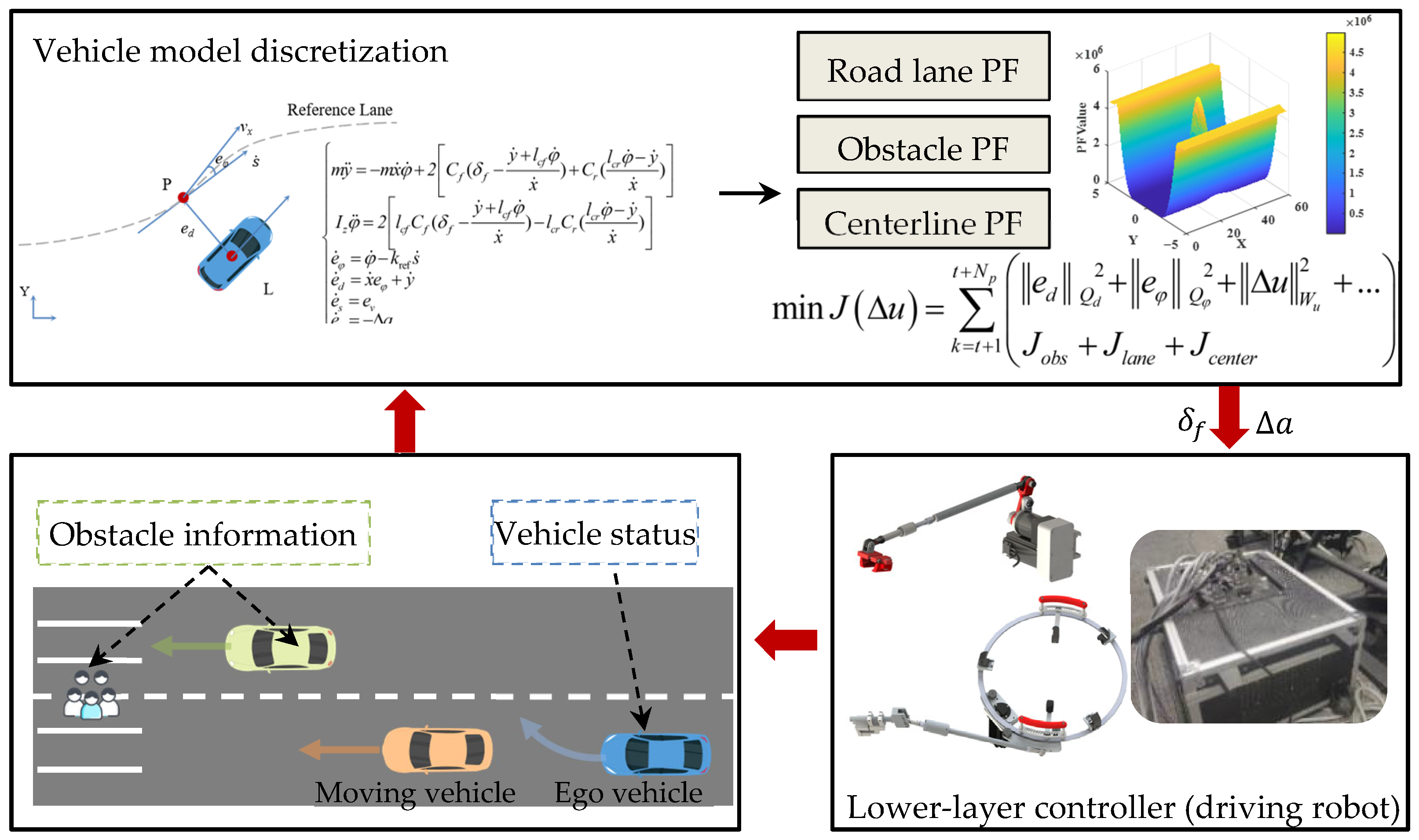
Figure 4 presents the obstacle avoidance control architecture for the driving robotic vehicle using enhanced artificial potential field-integrated MPC. The perception module handles obstacle detection and vehicle state information, which falls outside this paper’s research scope, with the assumption that obstacle locations are available to the vehicle. The obstacle information zobs(k) = [xobs(k), yobs(k), vobs(k)]T includes the position and velocity information of the dynamic obstacle. The vehicle state information can be obtained through the Carsim simulation environment, and passes to the discrete vehicle model. The potential field generation layer constructs three types of potential fields: the road lane potential field (Road Lane PF) is used to constrain the vehicle to travel within the lane; the obstacle potential field (Obstacle PF) is generated based on an improved adaptive Gaussian function; and the centerline potential field (Centerline PF) guides the vehicle to converge toward the road centerline. The improved obstacle potential field takes the relative velocity factor and obstacle risk level into account. The MPC optimization layer integrates the potential field functions into the objective function, constructing a multi-objective optimization problem that includes state tracking, control smoothness, and safe obstacle avoidance. The underlying control layer receives acceleration and steering commands from the MPC solver. These are converted into position vectors for the robot’s drive system using vehicle logic and the robot’s kinematic model, enabling precise control. The hierarchical architecture effectively decouples high-level decision-making from low-level execution: the upper MPC focuses on trajectory optimization based on the improved potential field, while the lower-level controller ensures the accurate execution of control commands. It enables safe and efficient obstacle avoidance navigation of the robotic vehicle in dynamic environments.

3.1. Vehicle Model Discretization

Section 2.2 presents the nonlinear vehicle error dynamics model, comprehensively illustrating the vehicle dynamic behavior. Given that MPC is an algorithm based on rolling optimization, it requires substantial computational resources. To alleviate the burden of real-time computation, model discretization employs the fourth-order Runge–Kutta (RK4) [38] integration technique. RK4’s fundamental principle involves approximating continuous state transition using multi-step Taylor expansion, converting it into a discrete iterative formula while maintaining accuracy. Within a control cycle Ts, RK4 approximates the state transition of the continuous system over the interval [kTs, (k + 1)Ts] through four intermediate state evaluations. The discretized vehicle model is shown in Equation (8):
k 1 = f ξ ( k ) , u ( k ) , θ r ( k ) k 2 = f ξ ( k ) + T s 2 k 1 , u ( k ) , θ r ( k ) k 3 = f ξ ( k ) + T s 2 k 2 , u ( k ) , θ r ( k ) k 4 = f ξ ( k ) + T s k 1 , u ( k ) , θ r ( k ) ξ ( k + 1 ) = ξ ( k ) + T s 6 k 1 + 2 k 2 + 2 k 3 + k 4
where f(⋅) represents the continuous-time dynamics function from Equation (7): f(ξ,u,θᵣ) = Aξ + B1u + B2θr, and k denotes the discrete time step. The fourth-order Runge–Kutta method assumes that the control inputs u(k) and θᵣ(k) remain constant throughout the sampling period Tₛ (zero-order hold assumption), while providing high-precision numerical integration for the vehicle state dynamics.

3.2. Obstacle Motion Model

To avoid obstacles, moving vehicles must avoid both static and moving obstacles. By considering the future motion states of obstacles, a motion model is established to predict the positions of obstacle vehicles. Assuming the state vector of an obstacle is zobs(k) = [xobs(k), yobs(k), φobs(k)]T, the obstacle motion model can be formulated using Equation (9):
x o b s ( k + 1 ) = x o b s ( k ) + T s v o b s ( k ) c o s φ o b s ( k ) y o b s ( k + 1 ) = y o b s ( k ) + T s v o b s ( t ) s i n φ o b s ( k ) φ o b s ( k + 1 ) = φ o b s ( k ) + T s w o b s ( k )
where xobs(k) and yobs(k) are the lateral and longitudinal positions of the obstacle in the global coordinate system at time step k, and φobs(k) is the yaw angle of the vehicle at time step k. Ts is the sampling time. For static obstacles or vehicles at constant velocity, setting wobs(k) = 0 simplifies the model. This reduces computational complexity. Using this motion model, the MPC controller can simulate the obstacle trajectory within the prediction horizon and achieve safe obstacle avoidance by integrating artificial potential fields or constraint conditions.

3.3. Multi-Objective Trajectory Planner Integrating Improved APF with MPC

In this section, a multi-objective obstacle avoidance trajectory planner integrating the APF and MPC is designed. By formulating a multi-objective and multi-constraint cost function, optimal control variables are determined through optimization methods, ensuring the vehicle’s ability to avoid emergency obstacles during reference trajectory tracking. The function uses improved environmental and obstacle potential fields, and a trajectory attraction model, to help the vehicle quickly return to its path. This function addresses multiple objectives and constraints. Additionally, it takes into account trajectory error and driving comfort constraints.

3.3.1. Improved Road Boundary PF

To represent the relationship between the vehicle and road boundaries more accurately, a three-circle vehicle model is adopted to approximate the vehicle’s geometric shape. This model simplifies the vehicle into three overlapping circles located at the vehicle’s center, front axle, and rear axle. The three-circle model can more accurately reflect the vehicle’s actual occupied space compared with the single-point model, especially for collision detection between the vehicle and boundaries. The vehicle is depicted by three circles as illustrated in Figure 5, with each circle’s location established by the vehicle’s geometric features. The vehicle’s centroid (xego, yego) is at the central circle’s center. The front- and rear-axle circles’ positions are calculated using the heading angle φ and offset distances from the centroid. This representation enables precise evaluation of the distance between the vehicle and road boundaries.
The position calculation formulas for the front-axle circle and rear-axle circle are as follows:
x f r o n t c i r c l e = x e g o + o f f s e t c o s ( φ ) y f o n r t c i c l e = y e g o + o f f s e t s i n ( φ ) x r e a r c i c l e = x e g o + o f f s e t c o s ( φ ) y r e a r c i c l e = y e g o + o f f s e t s i n ( φ )
The offset calculation formula relies on the vehicle’s length (L) and width (W):
o f f s e t = L 2 L 4 2 W 2 2
The length and width of general vehicles are approximately L = 4.8 m and W = 1.8 m, respectively. Standard road lane width is approximately 3.75 m (Wr). The road boundary repulsion function, shown in Equation (12), uses a three-circle vehicle model.
U b = 0 , d min i D L S n u D 2 L S , d min i 0 n u ( D 2 L S d min i ) 2 0 < d min i < D L S
where dmini indicates the shortest distance from the i-th circle to the road boundary, with i = 1, 2, 3 corresponding to the center circle, front-axle circle, and rear-axle circle, respectively.
The vehicle’s position is projected onto the road centerline to locate the closest point in the Frenet coordinate system, from which the relative distance dmini is calculated. Safety distance threshold DLS = rv + d0 (d0 is the safety margin, rv is radius of circle). nu is the potential field intensity coefficient. Figure 6 shows the three-dimensional potential field of the straight road and curve road. Colors range from cool (blue/green, lower Road PF Value) to warm (yellow, higher Road PF Value), visualizing spatial distribution of potential field intensity.

3.3.2. Dynamic/Static Obstacle PF

A unified PF modeling approach is proposed for static and dynamic obstacles by integrating relative motion information and spatial positional relationships into an adaptive Gaussian potential field. This model enhances the traditional Gaussian function with velocity sensitivity coefficients and smooth transition mechanisms, ensuring consistent potential field utilization and avoiding abrupt switching between different obstacle types. A risk-level modulation factor is introduced to construct the obstacle PF based on threat assessment in order to reflect the threat differences of obstacles with different risk levels. The potential field function U(x,y) at a point (x,y) in the environment is defined in Equation (13):
U o b s ( x , y ) = A o b s T l e v e l exp s rel 2 2 σ s 2 n rel 2 2 σ n 2 s rel = Δ x cos θ o b s + Δ y sin θ o b s n rel = Δ x sin θ o b s + Δ y cos θ o b s
where Aobs is the potential amplitude, Tlevel is the risk-level modulation factor. Obstacle risk is determined by type and movement. Low-risk obstacles (roadside facilities, posts) score 0.5; medium-risk (slow vehicles, non-motorized vehicles) score 0.8; and high-risk obstacles (pedestrians, fast lane changes) score 1.3. This classification mechanism realizes the risk adaptive change of the potential field intensity. High-threat obstacles automatically obtain stronger repulsive force to ensure that vehicles give priority to avoiding high-risk targets. (srel,nrel) represent the relative position of point (x,y) in the obstacle-centered coordinate system, where (Δxy) = (xx0,yy0) forms the relative position vector between the point (x,y) and the obstacle center (x0,y0). The obstacle heading angle is θobs.
To ensure precise responses for different motion modes, the potential field’s lateral standard deviation (σs) dynamically adjusts. The adjustment is based on the vehicle and obstacle’s relative positions and velocities. In the lateral direction, the standard deviation σn is determined by the obstacle width wobs.
σ s = λ σ s 1 + ( 1 λ ) σ s 2 λ = 1 2 1 + tanh s rel 2 σ n = w obs 2 + τ 2
where
σ s 1 = m a x ( m i n ( k v v s , rel 2 ,   s r e l 2 ) ,   σ b a s e ) v s , rel = ( v x , ego v x , obs ) cos θ o b s + ( v y , ego v y , obs ) sin θ o b s σ s 2 = ( L o b s + ε ) 2
kv is the velocity sensitive coefficient, and vs,rel is the relative velocity component in the obstacle-centered coordinate system. (vx,ego,vy,ego) and (vx,obs,vy,obs) represent the velocity components of the ego vehicle and the obstacle, respectively. σbase represents basic standard deviation. ε is the safety margin, and Lobs is the obstacle length. Figure 7 displays the obstacle potential field.
Remark 1: Through setting the basic standard deviation σbase = 3 m and safety margin ε = 0.1 m, it is ensured that even in the extreme case where the vehicle is relatively stationary with obstacle, there is still a minimum repulsion area, avoiding safety hazards caused by the disappearance of the potential field. The direct incorporation of obstacle geometric dimensions (Lobs,wobs) into the potential field parameter calculation organically integrates the physical boundaries of obstacles with the influence range of the potential field, effectively reducing collision risks. The switching function λ uses the hyperbolic tangent function to achieve smooth switching between the two potential field states, avoiding numerical oscillations and control instability caused by hard threshold switching. The introduction of the velocity-related term kvvs,rel2 enables the model to generate a differential response mechanism for obstacles in different motion states.
This adaptive mechanism allows the model to respond differently to obstacles in various motion states. For example, when |vs,rel| > |srel|, the potential field range in front of the obstacle expands gradually as the vehicle approaches, creating a “funnel-shaped” repulsive area. This guides the vehicle to adjust its trajectory in advance. For moving obstacles, when vs,rel > 0, the relative velocity term σs increases, extending the potential field’s influence range and generating preventive repulsive forces to avoid rear-end collisions. The higher the relative velocity, the earlier the repulsion is activated, providing sufficient time and space for safe evasion.

3.3.3. Trajectory Guidance PF

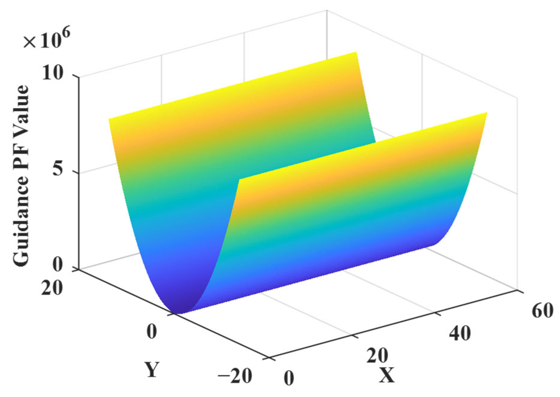
In autonomous navigation systems, cost functions are commonly designed to minimize state errors for accurate reference trajectory tracking. Repulsive forces from the obstacle potential field significantly deviate the vehicle from its reference path during obstacle avoidance. This makes it difficult to quickly resume the original trajectory. A trajectory guidance potential field function is introduced to address this limitation. It serves as an auxiliary control mechanism, steering the vehicle back to the reference trajectory, keeping it centered in the lane, and encouraging forward progress. The trajectory guidance PF is given in Equation (15):
U r e f ( x , y ) = A c e n t e r 1 exp k lat d lat 2 1 + 0.8 d lat 2
where Acenter is the potential field strength coefficient, controlling the overall magnitude of the attractive force. klat represents the lateral deviation sensitivity, determining how rapidly the potential increases with lateral displacement. dlat is the vehicle lateral deviation from the reference trajectory. The guidance potential field is shown in Figure 8.

3.3.4. MPC Multi-Constraint Optimization

Besides obstacles and environmental constraints, the objective function for establishing an MPC should also emphasize the tracking precision cost Jaccuray and the vehicle comfort Jcontrol. For tracking accuracy cost, it refers to minimizing lateral error and heading error, as shown below in Equation (16).
J a c c u r a y = k = t + 1 t + N p e d Q d 2 + e φ Q φ 2
where Np represents the prediction time domain, Qd indicates the weight matrix for minimizing the lateral error, and Qφ is the weight matrix for minimizing the heading error. The following cost function is adopted to restrict the system input increment at each time step for obtaining a smoother trajectory:
J c o n t r o l = k = t + 1 t + N p Δ u R u 2 = k = t + 1 t + N p R δ Δ δ f 2 ( k ) + R a Δ a 2 ( k )
where Ru = diag(Rδ,Ra) is the weighting matrix for controlling the increment, and Δδf(k) = δf(k) − δf(k − 1) is the increment for controlling the front-wheel steering angle.
Consequently, the trajectory planning cost function, within the prediction horizon Np, includes obstacle repulsion (Uobs), road boundary (Ub), and reference guidance (Uref) fields. This is expressed as follows:
m i n Δ u J Δ u = k = t + 1 t + N p e d Q d 2 + e φ Q φ 2 + Δ u W u 2 + J o b s + J l a n e + J c e n t e r s . t .     ξ ( k + 1 ) = f ξ ( k ) , u ( k ) , θ r ( k ) , k t , t + N p 1       u min u ( k ) u max , k t + 1 , t + N p       Δ u min Δ u ( k ) Δ u max , k t + 1 , t + N p       d o b s ( k ) d s a f e , o b s , k t + 1 , t + N p       d b o u n d ( k ) d s a f e , b o u n d , k t + 1 , t + N p       ξ t + 1 = ξ c u r r e n t
where f ξ ( k ) , u ( k ) , θ r ( k ) represents the vehicle state discretization function, which is mentioned in Section 3.1. umin and umax are the minimum and maximum values of the control input. Δumin and Δumax are the minimum and maximum values of the control input increment. dobs and dbound are the real-time distances between the vehicle and obstacles, and between the vehicle and road boundaries, respectively. dsafe,obs is the safety threshold between ego vehicle and obstacle vehicle. dsafe,bound is between the vehicle and road boundaries, which is set to about 0.8 m. xcurrent is the real-time feedback vehicle state.
Finally, the IPOPT [39] solver in CasADi is employed to address this nonlinear programming (NLP) problem, deriving the optimal front-wheel steering angle and acceleration control increments. IPOPT is capable of handling large-scale optimization problems with equality and inequality constraints, supports automatic differential and sparse matrix solving, and satisfies the real-time demands of MPC. The optimal control increment outputs by IPOPT are converted into physical control quantities for the drive system by integrating the kinematic model of the driving robot.

4. Simulation and Experiment

A joint simulation experiment of Carsim/Simulink and the driving simulator is conducted in this section to assess the effectiveness of the proposed upper-level obstacle avoidance algorithm. Static and dynamic obstacles are placed on straight roads and curves, respectively. Improved APF-MPC (IMAPF-MPC) is compared with two other obstacle avoidance strategies (traditional APF-MPC and APF-MPC without a guided potential field) to verify its obstacle avoidance performance. Then, a semi-physical experimental platform is constructed, and the IMAPF is combined with the driving system of the driving robot to accomplish the obstacle avoidance task in complex road conditions, and the avoidance effect of the proposed obstacle avoidance strategy is further observed.

4.1. Simulation Results

The purpose of the avoidance algorithm is to effectively avoid obstacles when encountering them, and then return the test route to continue vehicle road tests. The virtual real-time module of G29 driving simulator and Carsim is constructed. IMAPF-MPC obtains the vehicle state information from the high-fidelity Carsim environment and calculates the front-wheel steering angle required for obstacle avoidance. The signal is transformed into the steering control signal of the driving simulator, allowing the vehicle to execute steering-based obstacle avoidance. The simulation block diagram is shown in Figure 9. Table 1 presents the relevant vehicle parameters and MPC parameters. The vehicles in Carsim use C-class vehicles.
(1)
Static obstacle avoidance
As shown in Figure 10, the control vehicle travels at 15 m/s, and the first static obstacle is 40 m from the initial position of the vehicle. Three stationary obstacle vehicles are positioned on the road along the control vehicle’s path, with 30 m spacing between consecutive obstacle vehicle positions.
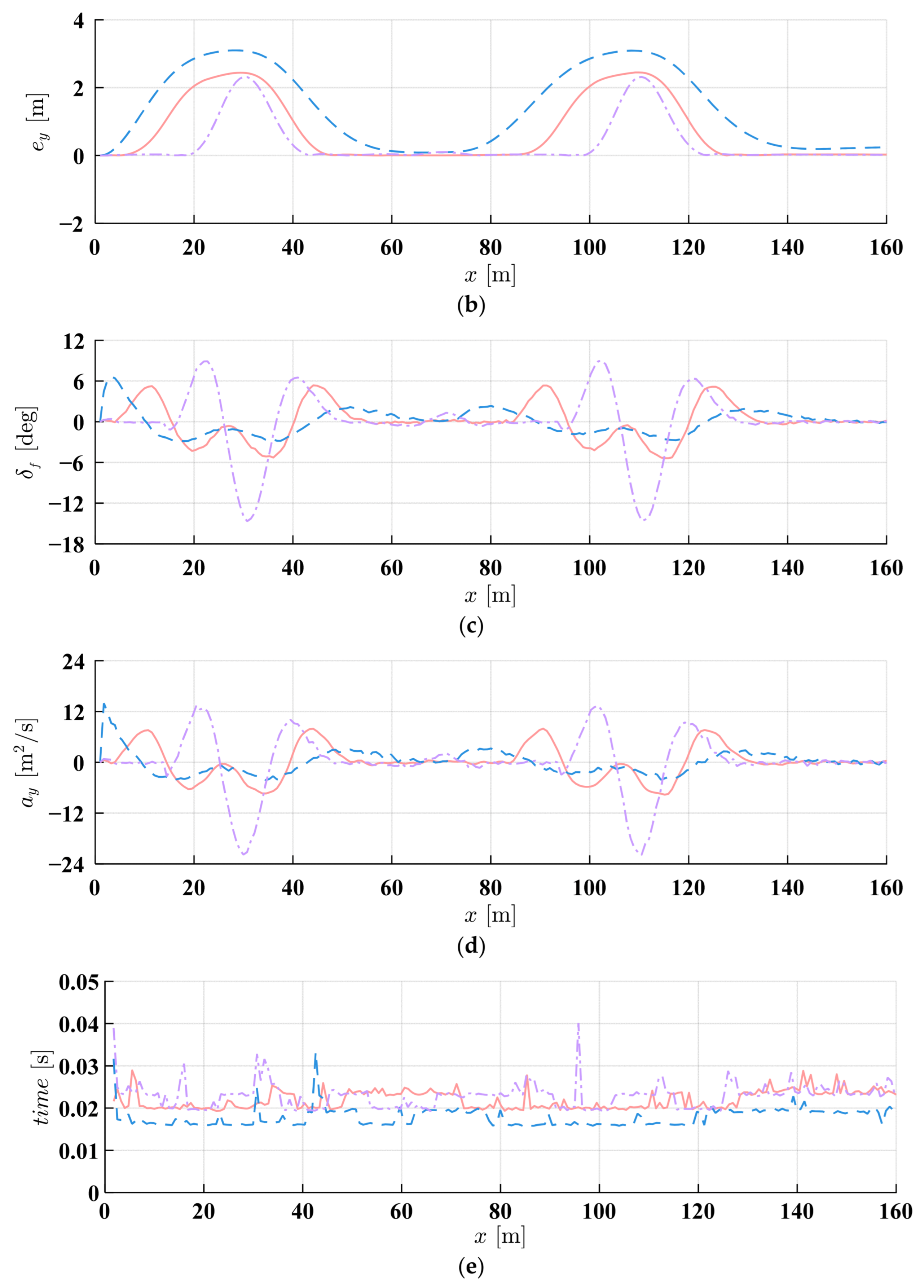
The simulation results are shown in Figure 11. The colored three circles represent the ego vehicles. The gray rectangles denote static obstacle vehicles. According to Figure 11a, when the ego vehicle encounters three stationary obstacle vehicles, all three obstacle avoidance algorithms successfully prevent collisions. However, significant differences in avoidance behavior and trajectory characteristics are observed among the algorithms. Figure 11b shows the tracking error of three obstacle avoidance algorithms. The APF-MPC without guidance has a maximum tracking error. Because of the absence of auxiliary attractive forces, the vehicle exhibits slower convergence to the reference trajectory after obstacle clearance. Moreover, once the vehicle returns to the reference path, larger tracking errors persist, indicating suboptimal trajectory following performance. The traditional APF-MPC exhibits more aggressive and emergency-like avoidance maneuvers, characterized by sharp lateral movements and abrupt steering corrections when approaching obstacles. In contrast, the proposed IMAPF-MPC demonstrates a more anticipatory and composed avoidance strategy, initiating lane-changing maneuvers earlier and executing smoother trajectory adjustments. The IMAPF-MPC algorithm shows superior path-following performance after obstacle avoidance completion. The vehicle can return the reference trajectory accurately and maintain stable tracking with minimal oscillations. This behavior is attributed to attractive PF that guides the vehicle back to the desired path systematically. Figure 11c,d show the stable and smooth front angle wheel and lateral acceleration of IMAPF-MPC. In contrast, the unguided APF-MPC shows abrupt initial front-wheel steering angles and lateral acceleration, resulting in unstable vehicle handling. Figure 11e shows the solution time in each adoption cycle of the three algorithms. The three obstacle avoidance algorithms are all less than the set sampling cycle of 0.05, meeting the real-time requirements.
Table 2 shows that the IMAPF-MPC has the minimum front-wheel steering angle and lateral acceleration. The lateral acceleration (7.943 m/s2 vs. 21.902 m/s2) is significantly reduced by 63.7% compared with the traditional APF-MPC. These improvements translate to enhanced passenger comfort, reduced vehicle stress, and improved overall system reliability in practical autonomous driving scenarios.
To further validate the effectiveness of the IMAPF-MPC algorithm, a more challenging curved road scenario is designed. Figure 12 shows the control ego vehicle traveling at 15 m/s through an s-curve. Three stationary obstacle vehicles are positioned at 30 m, 60 m, and 120 m.
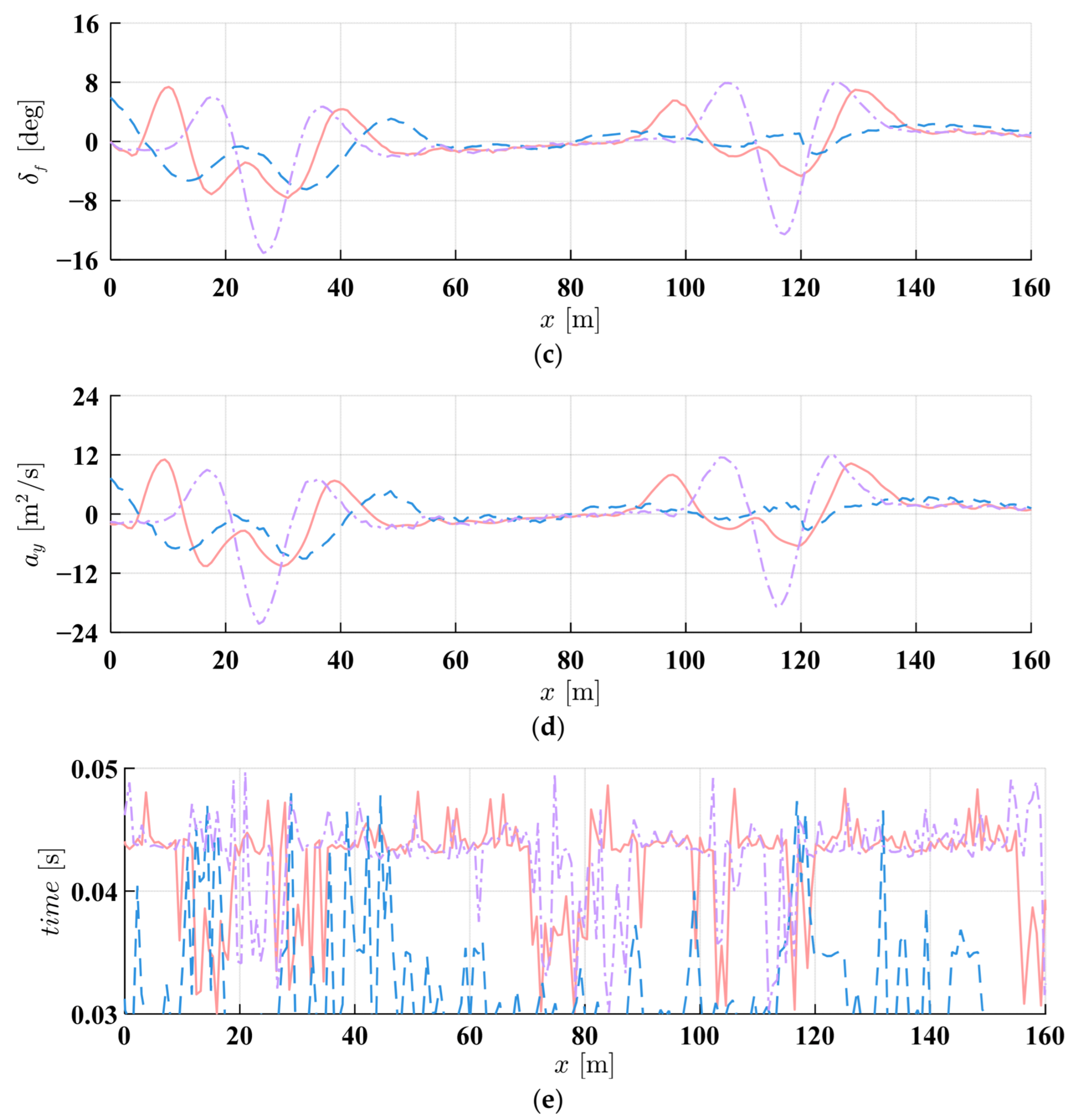
Figure 13 presents the simulation results of the three collision avoidance algorithms when encountering static obstacles in the S-shaped curve. Figure 13a shows that the IMAPF-MPC, even in a curve state, functions identically to the straight state, allowing for early obstacle prediction and avoidance. According to Figure 13b–d, the conventional APF-MPC demonstrates the most aggressive avoidance behavior with the maximum front-wheel steering angle and lateral acceleration. The unguided APF-MPC exhibits intermediate performance but lacks the system trajectory optimization of the proposed method. Although it successfully completes the avoidance task, the behavior after avoidance has obvious defects in returning to the reference path, with large oscillations and slow convergence. In Figure 13, when avoiding obstacles on a large curved road, although the solution time increases, IMAPF-MPC still meets the real-time requirements.
Table 3 shows IMAPF-MPC significantly outperforms traditional APF-MPC. Peak lateral acceleration decreased by 50.3% (22.141 m/s2 to 11.005 m/s2) and peak front-wheel steering angle by 41.1% (15.080° to 7.641°), improving vehicle smoothness and passenger comfort.
(2)
Dynamic obstacle avoidance
The previous scenario focuses on avoiding multiple static obstacles. In this section, the host vehicle maintains forward movement at 15 m/s. An obstacle vehicle designated as Car 1 is present on the current lane, traveling at 8 m/s and positioned 30 m from the target vehicle’s initial location, which is shown in Figure 14.
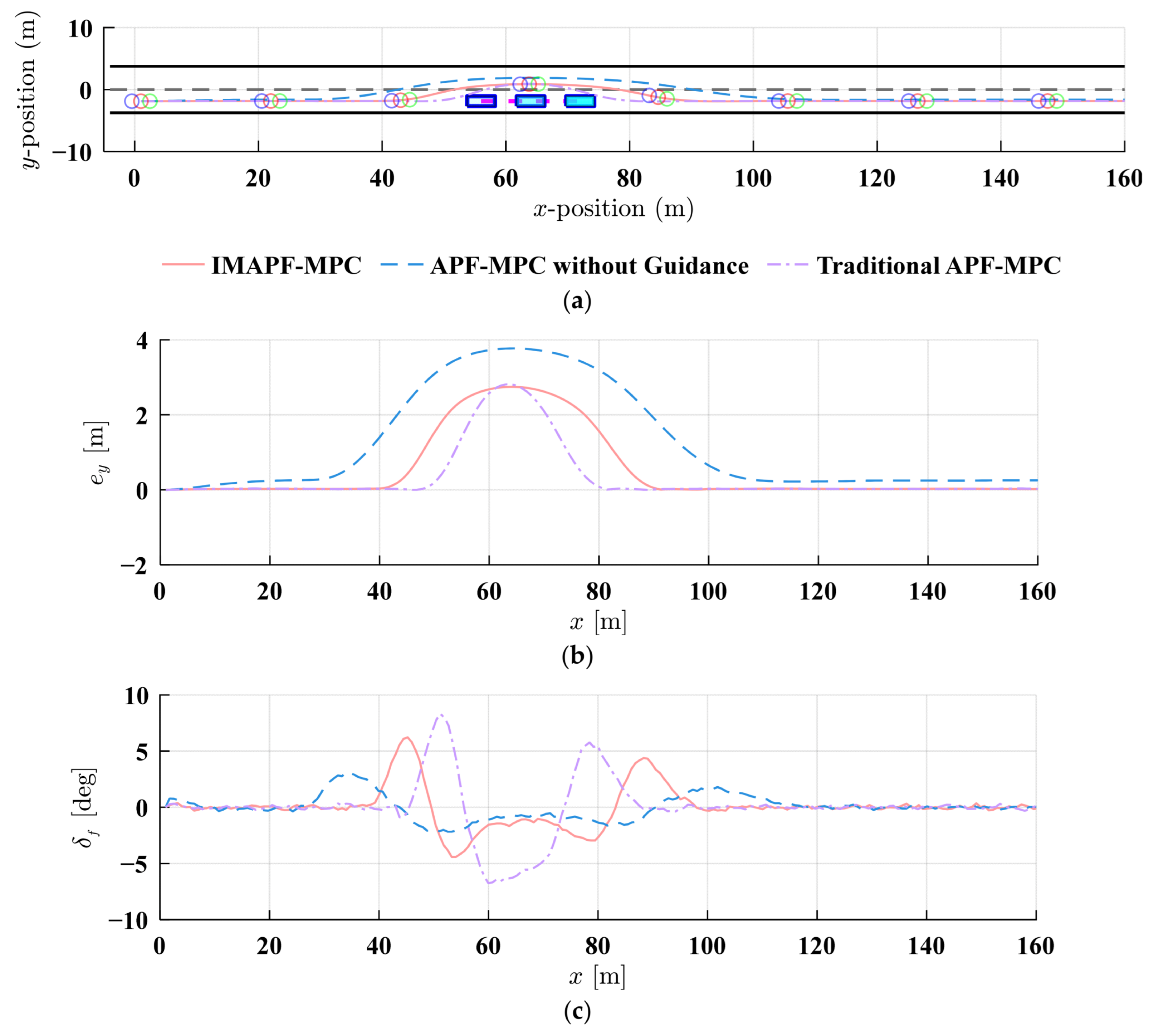
Figure 15a shows the obstacle avoidance effect of a vehicle encountering a dynamic obstacle on a straight road. In the critical obstacle avoidance area, the traditional APF-MPC collides with the bounding box of the obstacle because the shape of the vehicle is not considered. Compared with APF-MPC without guidance, the improved APF-MPC can still return to the right centerline quickly after the obstacle avoidance of the moving vehicle. According to the tracking trajectory curve in Figure 15b, APF-MPC without guidance has the largest tracking error. Figure 15c,d demonstrate the front-wheel steering angle and lateral acceleration for all three obstacle avoidance strategies, respectively. The front-wheel steering angle and lateral acceleration under unguided APF-MPC are the lowest, but the curve fluctuations are frequent and the tracking task is not completed. The traditional APF-MPC has the largest front-wheel steering angle and lateral acceleration, leading to unstable obstacle avoidance behavior and reduced comfort. According to Figure 15e, the solution time curve of the three algorithms when avoiding dynamic obstacles on the straight road is similar to that when avoiding static obstacles on the straight road, meeting the requirements of real-time control.
Table 4 reveals that the IMAPF-MPC achieves a maximum tracking error of 2.749 m, with maximum lateral acceleration and front-wheel steering angle of 9.024 m/s2 and 6.220°, respectively.
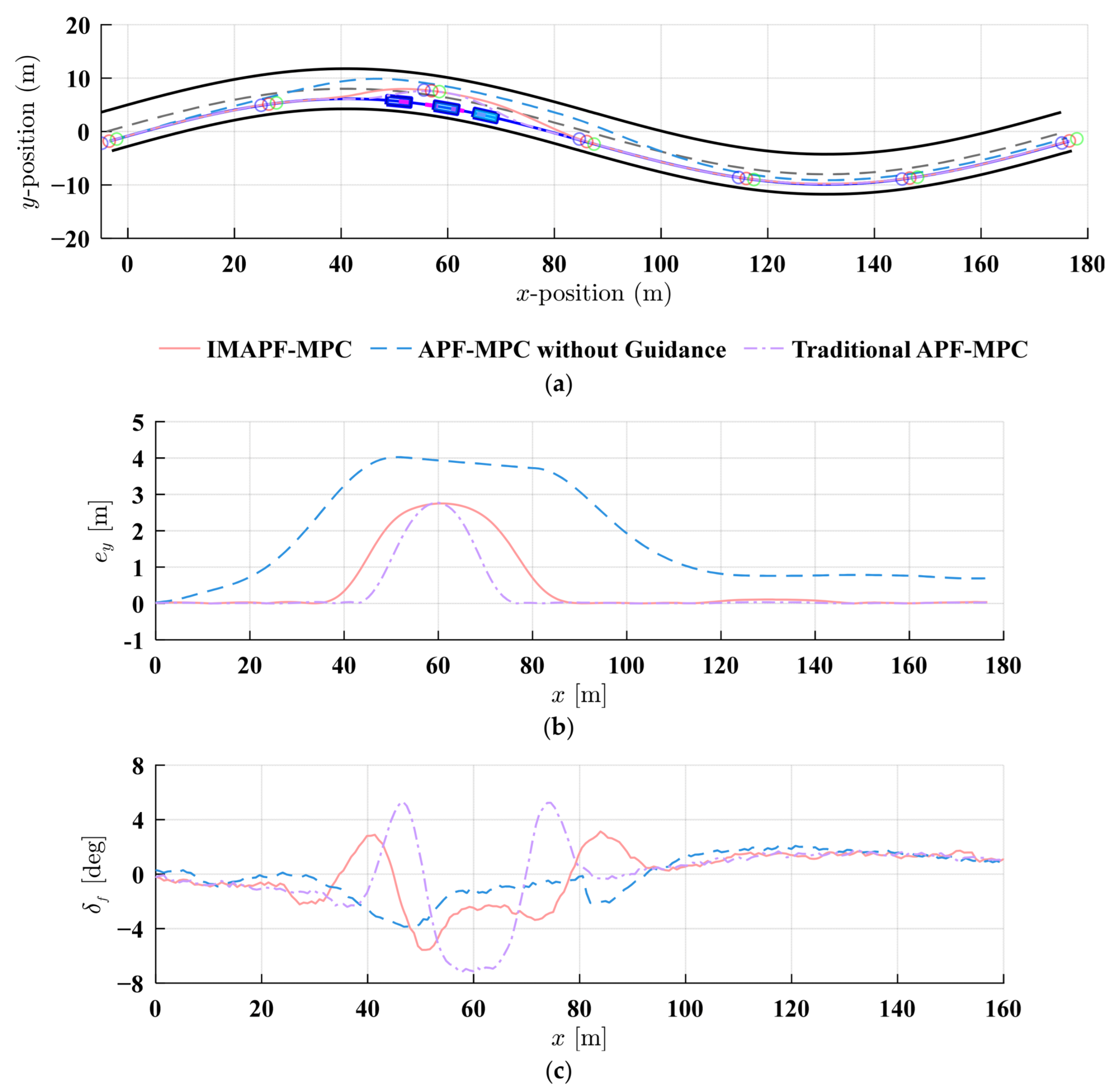
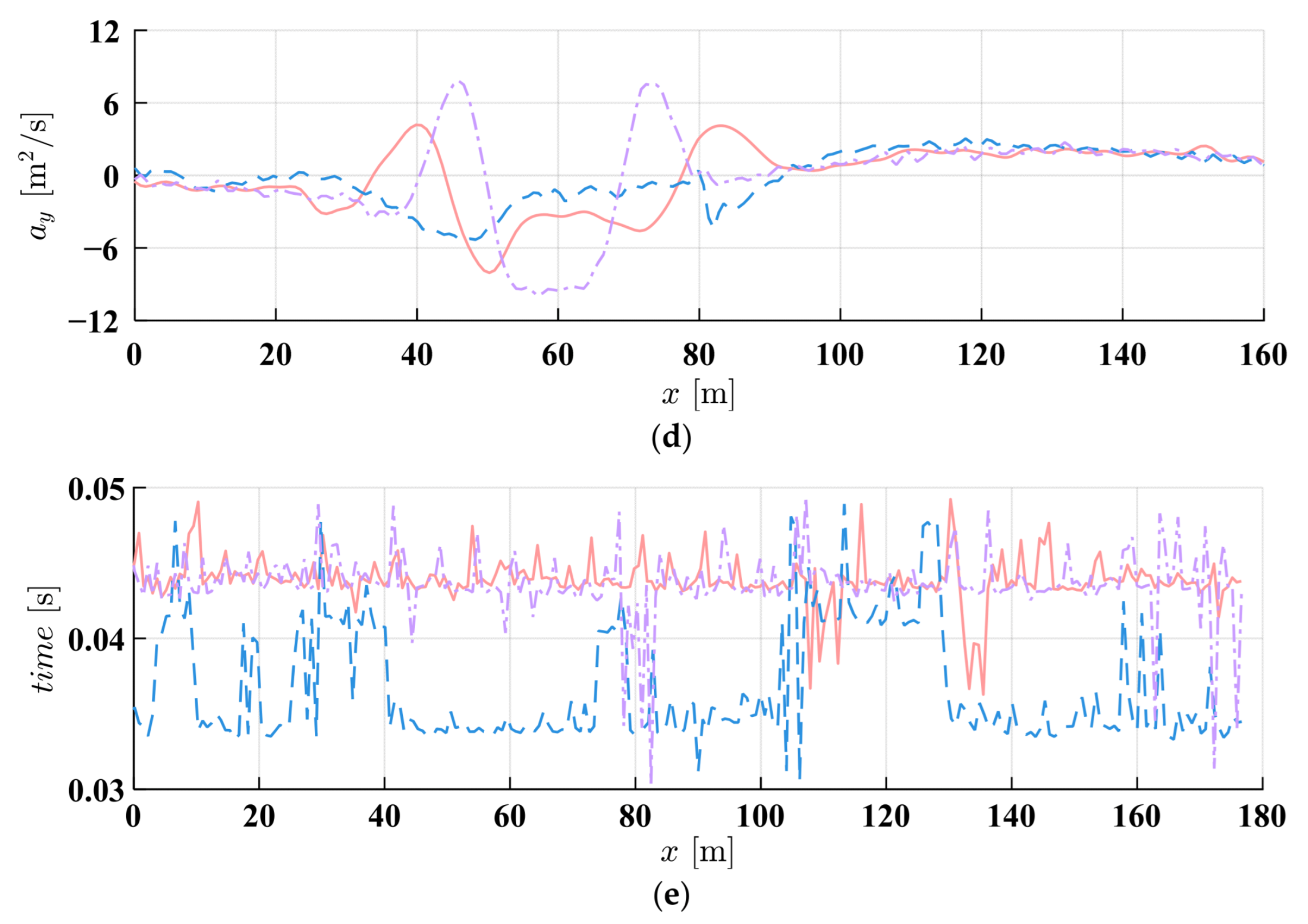
The following scenario, as depicted in Figure 16, is designed to verify the capability of avoiding moving obstacles on the curved road. Similarly to the straight scenario, the obstacle vehicle continues at 8 m/s and travels along the right lane’s centerline.
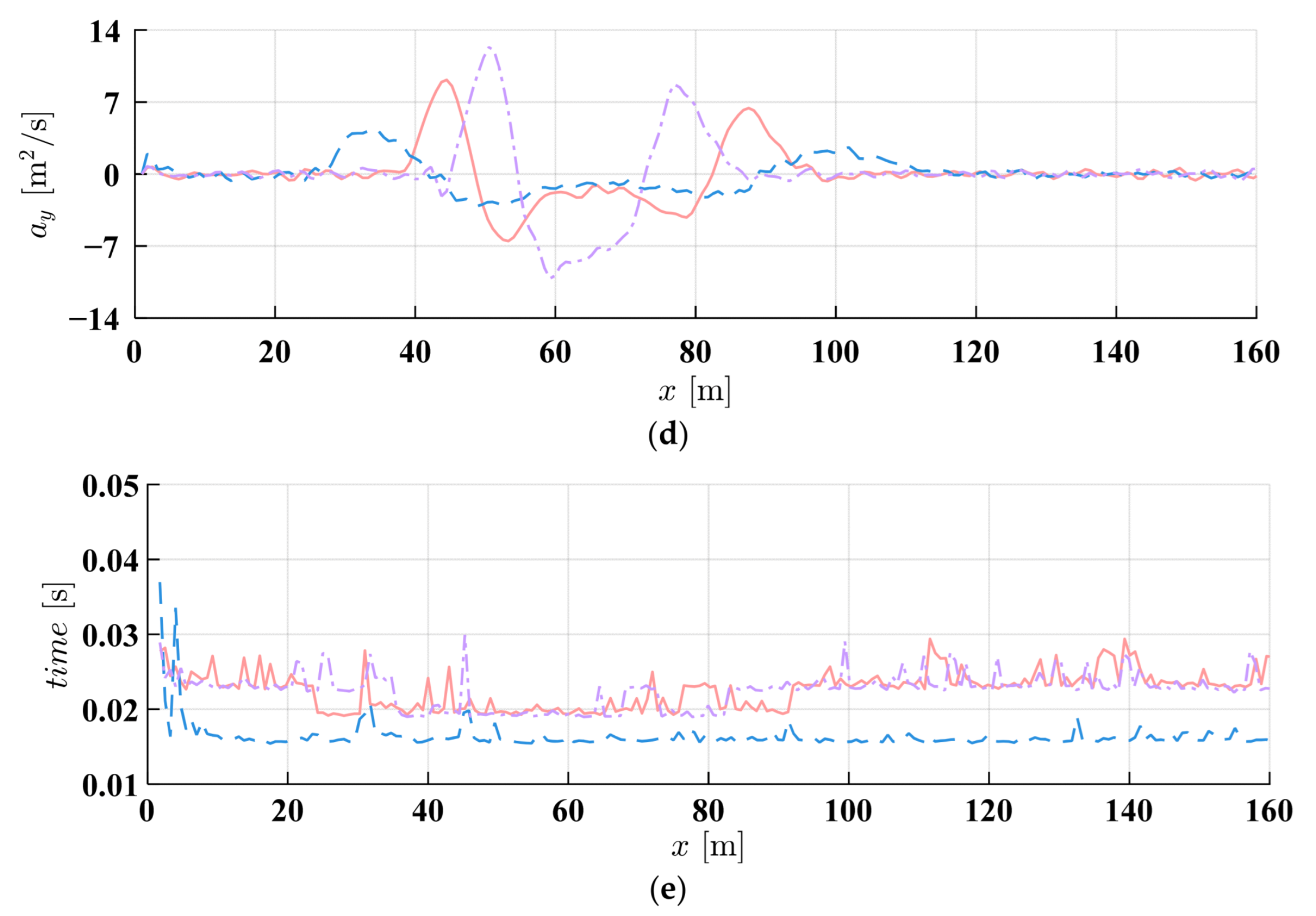
Figure 17a shows the obstacle avoidance effects of different strategies for dynamic obstacles on curved roads. As the obstacle vehicle approaches the high-curvature road section (x = 50–70), the ego vehicle starts obstacle avoidance, with IMAPF-MPC completing the dynamic obstacle avoidance task efficiently and stably. As road curvature increases gradually, APF-MPC without a guided potential field finds it difficult to return to the reference trajectory after obstacle avoidance completion. Consequently, the tracking task is not completed successfully. The tracking error comparison in Figure 17b shows that IMAPF-MPC maintains the smallest tracking error during the whole obstacle avoidance process, while APF-MPC without guidance achieves the largest tracking error. Especially after obstacle avoidance (x > 100 m), IMAPF-MPC rapidly converges to zero error, unlike the other methods which show large residual errors. This highlights that the proposed attractive potential field significantly enhances system steady-state performance. Figure 17c,d illustrate front-wheel steering angle and lateral acceleration variations, respectively. In the critical obstacle avoidance zone within the curve (x = 40–80 m), the traditional APF-MPC exhibits the most drastic control input changes, with front-wheel steering angle peaks reaching approximately 6°, and the peak of the lateral acceleration exceeds 8 m/s2. This sharp control change not only affects the ride comfort but may also cause vehicle instability. Conversely, the control input of IMAPF-MPC is more moderate, with front-wheel steering angle peaks around 3.5°, and lateral acceleration peaks approximately 4 m/s2, which reflects the better control smoothness. Figure 17e shows the solution time for each sampling time when avoiding dynamic obstacle on the s-curved road. The solution time fluctuation of the proposed APF-MPC strategy is relatively small, still less than the sampling time of 0.05. Although the solution time of traditional APF-MPC is the smallest, it does not effectively complete obstacle avoidance and trajectory tracking.
The statistical data in Table 5 further validate the above analytical conclusions. In the S-shaped curve dynamic obstacle avoidance scenario, IMAPF-MPC achieves optimal performance in lateral acceleration control, with a maximum value of 7.204 m/s2, which is 27.4% lower than the 9.921 m/s2 of the traditional APF-MPC, significantly improving ride comfort. Although the maximum tracking error of IMAPF-MPC (2.752 m) is similar to that of the conventional APF-MPC (2.768 m), the results show that IMAPF-MPC has faster convergence speed and smaller steady-state error combined with the time-domain response in Figure 17b. Based on dynamic obstacle avoidance in S-shaped curves, the IMAPF-MPC algorithm can still maintain excellent obstacle avoidance performance and trajectory tracking accuracy under complex road geometry conditions, demonstrating the effectiveness and practicality of the proposed method.

4.2. Experimental Results

Previous software-in-the-loop simulations show that IMAPF-MPC outperforms traditional APF-MPC and APF-MPC without attractive potential fields in obstacle avoidance. It also shows more proactive avoidance behavior. To further confirm the practical applicability of the proposed algorithm, a hardware-in-the-loop experimental platform was constructed, integrating the driving robot’s low-level control system with the proposed upper-level obstacle avoidance decision-making algorithm. The overall diagram of real-time semi-physical experiment platform is shown in Figure 18. The lower-level decision-making system is combined with the upper obstacle avoidance decision-making algorithm. The MPC calculates the necessary vehicle acceleration and front-wheel steering angle. The inverse engine model of the vehicle and a PID algorithm translate vehicle acceleration into the required accelerator pedal angle. The motor control signal is then obtained using the driving robot’s transfer function (as discussed in Section 2.1). This part will not be introduced in detail here.
The real-time semi-physical platform architecture includes a G29 driving simulator, driving robot drive control module, OP4510-v2, computer and display module. The integration process involves loading the designed upper-level decision algorithm into the real-time simulator, and developing a closed-loop system in Simulink that integrates the G29 driving simulator and Carsim module. The integrated system outputs the status information of the Carsim virtual vehicle and transmits it to the OP4510-V2 controller. The OP4510-V2 controller acts as a real-time controller and sends position signals to the driving robot’s control module to complete steering and speed control. This process realizes comprehensive vehicle control of the virtual vehicle and forms a complete closed-loop system.
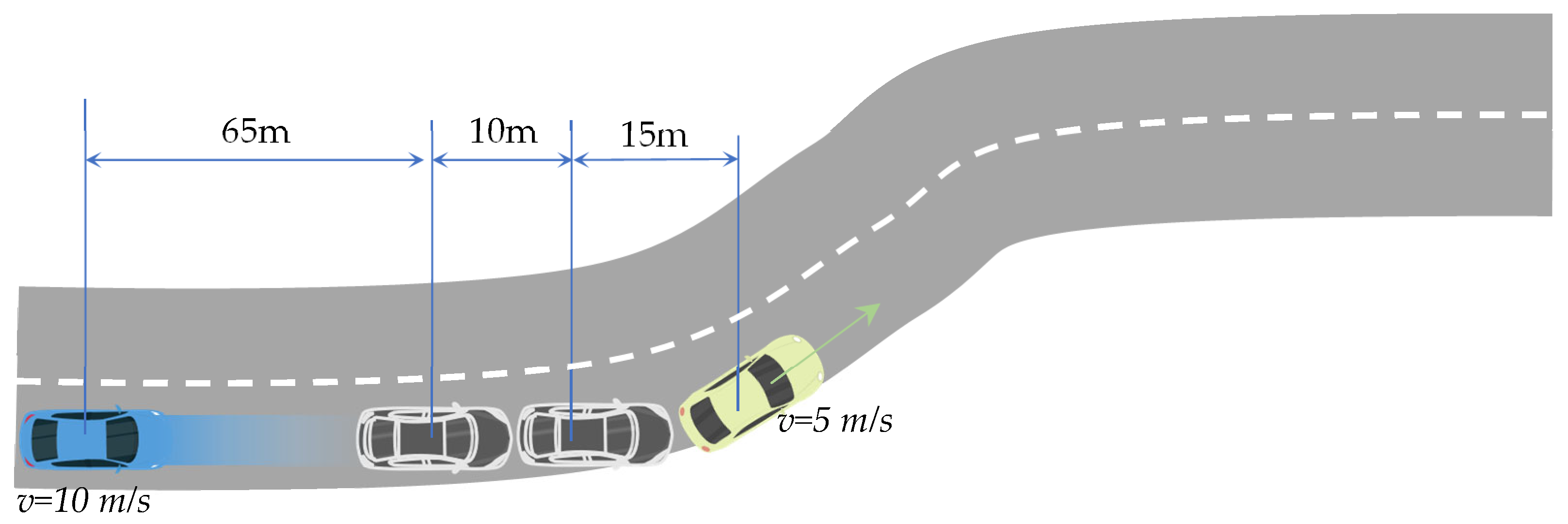
A comprehensive test scenario was designed to evaluate the algorithm’s performance under complex traffic conditions. As shown in Figure 19, a trajectory containing both straight lines and curves is constructed with a total length of 250 m. The ego vehicle maintains a constant speed of 10 m/s throughout the experiment. Two static obstacle vehicles are located in the right traffic lane. One moving obstacle vehicle proceeds at 5 m/s in an identical direction to the host vehicle.
Figure 20 emonstrates that the IMAPF-MPC algorithm effectively avoids both static and dynamic obstacles, returning to the reference centerline. When encountering static obstacles, the obstacle avoidance maneuver occurs within the range of x = 40~80 m, and the vehicle maintains stable performance throughout this process. For the dynamic obstacle vehicle, the control vehicle starts the obstacle avoidance task at t = 7.7 s and completes it at t = 7.9 s. The overall obstacle avoidance trajectory is relatively smooth, maintaining a reasonable safe distance from the dynamic vehicle throughout the interaction period.
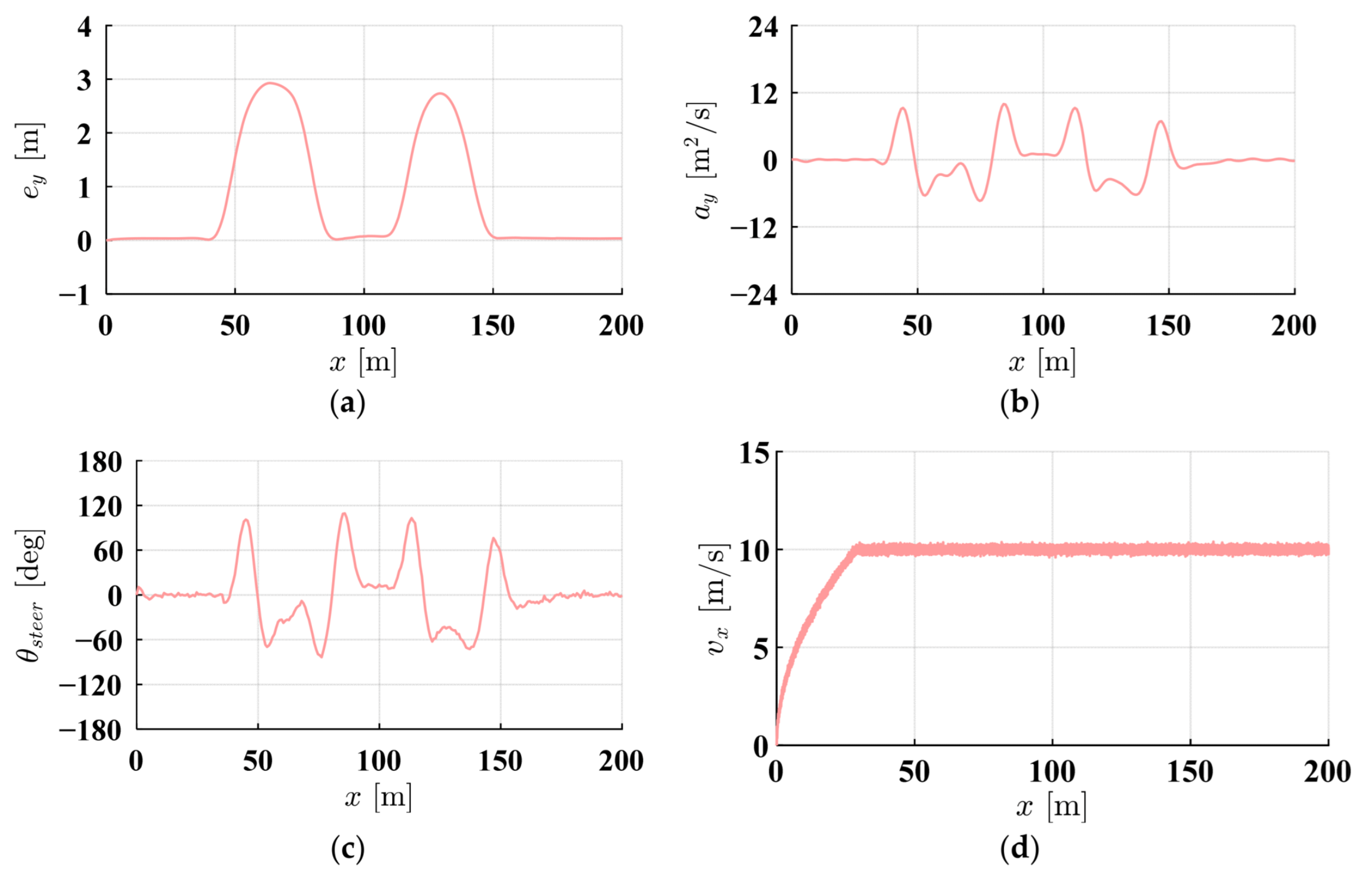
Figure 21a–c reveal that throughout the avoidance process, the target vehicle demonstrates a peak lateral tracking deviation of roughly 3 m. The lateral acceleration maintains smooth variations with maximum values around 11 m/s2, indicating comfortable avoidance behavior without excessive lateral forces that could compromise passenger comfort. The steering angle exhibits smooth and continuous variations without abrupt changes, contributing significantly to vehicle stability and ride quality. Examining the velocity profile in Figure 21d, the vehicle basically maintains a consistent speed of 10 m/s throughout the entire experiment.
The experimental results conclusively demonstrate that the integrated IMAPF-MPC algorithm, combined with the underlying motor control system, maintains stable and robust performance throughout the complex mixed-obstacle scenario. The consistently smooth control inputs and accurate trajectory tracking validate the practical feasibility of the IMAPF-MPC algorithm for real-world driving applications.

5. Conclusions

To meet Autonomous Robot Vehicle (ADRV) road-testing safety requirements, an obstacle avoidance strategy based on improved APF-MPC was proposed. The proposed method handles static and dynamic obstacles through a unified potential field constraint design, and the three-circular vehicle modeling provides an accurate boundary constraint representation for arbitrary curvature roads, ensuring collision avoidance performance across diverse scenarios. The environment-adaptive potential field method, based on the Frenet coordinate system combined with the auxiliary attractive potential field, ensures the stable trajectory recovery after the completion of obstacle avoidance. This solves the key limitation of traditional APF methods, where vehicles struggle to return to the reference path. Vehicle dynamics and road geometric variations are fully integrated into the control framework, with a comprehensive consideration of environmental constraints including road boundaries and curvature limits. The proposed IMAPF-MPC method can effectively minimize vehicle maximum lateral acceleration and improve the ride comfort during avoiding obstacle through smooth steering control. Extensive simulation and experimental results demonstrate the superior performance of the proposed IMAPF-MPC algorithm, which is summarized as follows.
(1)
IMAPF-MPC successfully handles static and dynamic obstacle scenarios on straight and curved roads. In the static obstacle avoidance of a straight road, compared with the traditional APF-MPC, the developed method’s peak lateral acceleration decreases by 63.7% (from 21.902 m/s2 to 7.943 m/s2), while maintaining a comparable tracking accuracy. The maximum tracking error is 2.449 m. IMAPF-MPC shows better adaptability in dynamic obstacle scenarios, which leads to significantly reduced steering oscillations and improved passenger comfort.
(2)
The semi-physical experimental platform shows that, by combining the proposed obstacle avoidance strategy with the driving system of the underlying driving robot, the IMAPF-MPC can effectively complete the obstacle avoidance task and maintain good trajectory tracking performance in complex road scenes with dynamic and static obstacles. The testing outcomes validate the practicality and reliability of the algorithm within real hardware configurations.
Although the current improved strategy shows relatively good performance, future work should focus on (i) cooperative obstacle avoidance strategies for multi-vehicle testing and integration of vehicle-to-vehicle communication (V2V) for predictive obstacle detection, and (ii) optimization of the robust algorithm for obstacle motion uncertainty and environmental perception noise.

Author Contributions

Conceptualization, L.Z. and W.N.; methodology, L.Z.; software, L.Z.; validation, L.Z.; formal analysis, L.Z.; investigation, L.Z.; resources, W.N.; data curation, L.Z.; writing—original draft preparation, L.Z.; writing—review and editing, L.Z., H.L.; visualization, L.Z.; supervision, W.N.; project administration, W.N.; funding acquisition, W.N. All authors have read and agreed to the published version of the manuscript.

Funding

This research received no external funding.

Data Availability Statement

Datasets mentioned in the paper are available from the authors upon reasonable request.

Conflicts of Interest

The authors declare no conflicts of interest.

References

  1. Wang, H.; Chen, G.; Zhang, W. A Method for Vehicle Speed Tracking by Controlling Driving Robot. Trans. Inst. Meas. Control 2020, 42, 1521–1536. [Google Scholar] [CrossRef]
  2. Chen, G.; Chen, S.; Langari, R.; Li, X.; Zhang, W. Driver-Behavior-Based Adaptive Steering Robust Nonlinear Control of Unmanned Driving Robotic Vehicle with Modeling Uncertainties and Disturbance Observer. IEEE Trans. Veh. Technol. 2019, 68, 8183–8190. [Google Scholar] [CrossRef]
  3. Liang, J.; Li, Y.; Yin, G.; Xu, L.; Lu, Y.; Feng, J.; Shen, T.; Cai, G. A MAS-Based Hierarchical Architecture for the Cooperation Control of Connected and Automated Vehicles. IEEE Trans. Veh. Technol. 2023, 72, 1559–1573. [Google Scholar] [CrossRef]
  4. Chen, G.; Su, S. Driver-Behavior-Based Robust Steering Control of Unmanned Driving Robotic Vehicle with Modeling Uncertainties and External Disturbance. Proc. Inst. Mech. Eng. Part D J. Automob. Eng. 2020, 234, 1585–1596. [Google Scholar] [CrossRef]
  5. Yang, L.; Li, P.; Qian, S.; Quan, H.; Miao, J.; Liu, M.; Hu, Y.; Memetimin, E. Path Planning Technique for Mobile Robots: A Review. Machines 2023, 11, 980. [Google Scholar] [CrossRef]
  6. Debnath, D.; Vanegas, F.; Sandino, J.; Hawary, A.F.; Gonzalez, F. A Review of UAV Path-Planning Algorithms and Obstacle Avoidance Methods for Remote Sensing Applications. Remote Sens. 2024, 16, 4019. [Google Scholar] [CrossRef]
  7. Zhang, R.; Hao, G.; Zhang, K.; Li, Z. Unmanned Aerial Vehicle Navigation in Underground Structure Inspection: A Review. Geol. J. 2023, 58, 2454–2472. [Google Scholar] [CrossRef]
  8. Li, C.; Huang, X.; Ding, J.; Song, K.; Lu, S. Global Path Planning Based on a Bidirectional Alternating Search A* Algorithm for Mobile Robots. Comput. Ind. Eng. 2022, 168, 108123. [Google Scholar] [CrossRef]
  9. Wang, H.; Qi, X.; Lou, S.; Jing, J.; He, H.; Liu, W. An Efficient and Robust Improved A* Algorithm for Path Planning. Symmetry 2021, 13, 2213. [Google Scholar] [CrossRef]
  10. Xu, B. Precise Path Planning and Trajectory Tracking Based on Improved A-Star Algorithm. Meas. Control 2024, 57, 1025–1037. [Google Scholar] [CrossRef]
  11. Ravankar, A.A.; Ravankar, A.; Emaru, T.; Kobayashi, Y. HPPRM: Hybrid Potential Based Probabilistic Roadmap Algorithm for Improved Dynamic Path Planning of Mobile Robots. IEEE Access 2020, 8, 221743–221766. [Google Scholar] [CrossRef]
  12. Raheem, F.A.; Abdulkareem, M.I. Development of Path Planning Algorithm Using Probabilistic Roadmap Based on Modified Ant Colony Optimization. World J. Eng. Technol. 2019, 7, 583–597. [Google Scholar] [CrossRef]
  13. Yu, J.; Chen, C.; Arab, A.; Yi, J.; Pei, X.; Guo, X. RDT-RRT: Real-Time Double-Tree Rapidly-Exploring Random Tree Path Planning for Autonomous Vehicles. Expert Syst. Appl. 2024, 240, 122510. [Google Scholar] [CrossRef]
  14. Li, Q.; Xu, Y.; Bu, S.; Yang, J. Smart Vehicle Path Planning Based on Modified PRM Algorithm. Sensors 2022, 22, 6581. [Google Scholar] [CrossRef]
  15. Huang, T.; Fan, K.; Sun, W. Density Gradient-RRT: An Improved Rapidly Exploring Random Tree Algorithm for UAV Path Planning. Expert Syst. Appl. 2024, 252, 124121. [Google Scholar] [CrossRef]
  16. Chen, Q.; Yu, B.; Min, S.; Gan, L.; Luo, C.; Zeng, D.; Hu, Y.; Liu, Q. Study on Intelligent Vehicle Trajectory Planning and Tracking Control Based on Improved APF and MPC. Int. J. Automot. Technol. 2025, 26, 715–728. [Google Scholar] [CrossRef]
  17. Wu, H.; Zhang, Y.; Huang, L.; Zhang, J.; Luan, Z.; Zhao, W.; Chen, F. Research on Vehicle Obstacle Avoidance Path Planning Based on APF-PSO. Proc. Inst. Mech. Eng. Part D J. Automob. Eng. 2023, 237, 1391–1405. [Google Scholar] [CrossRef]
  18. Jayaweera, H.M.; Hanoun, S. A Dynamic Artificial Potential Field (D-APF) UAV Path Planning Technique for Following Ground Moving Targets. IEEE Access 2020, 8, 192760–192776. [Google Scholar] [CrossRef]
  19. Feng, S.; Qian, Y.; Wang, Y. Collision Avoidance Method of Autonomous Vehicle Based on Improved Artificial Potential Field Algorithm. Proc. Inst. Mech. Eng. Part D J. Automob. Eng. 2021, 235, 3416–3430. [Google Scholar] [CrossRef]
  20. Li, W.; Wang, Y.; Zhu, S.; Xiao, J.; Chen, S.; Guo, J.; Ren, D.; Wang, J. Path Tracking and Local Obstacle Avoidance for Automated Vehicle Based on Improved Artificial Potential Field. Int. J. Control Autom. Syst. 2023, 21, 1644–1658. [Google Scholar] [CrossRef]
  21. Azzabi, A.; Nouri, K. An Advanced Potential Field Method Proposed for Mobile Robot Path Planning. Trans. Inst. Meas. Control 2019, 41, 3132–3144. [Google Scholar] [CrossRef]
  22. Pan, Z.; Zhang, C.; Xia, Y.; Xiong, H.; Shao, X. An Improved Artificial Potential Field Method for Path Planning and Formation Control of the Multi-UAV Systems. IEEE Trans. Circuits Syst. II Express Briefs 2022, 69, 1129–1133. [Google Scholar] [CrossRef]
  23. Hammad, S. Path Tracking Control Based on an Adaptive MPC to Changing Vehicle Dynamics. Int. J. Mech. Eng. Robot. Res. 2022, 11, 535–541. [Google Scholar] [CrossRef]
  24. Liu, X.; Ou, J.; Yan, D.; Zhang, Y.; Deng, G. Path Tracking Control of Automated Vehicles Based on Adaptive MPC in Variable Scenarios. IET Intell. Transp. Syst. 2024, 18, 1031–1044. [Google Scholar] [CrossRef]
  25. Zuo, Z.; Yang, X.; Li, Z.; Wang, Y.; Han, Q.; Wang, L.; Luo, X. MPC-Based Cooperative Control Strategy of Path Planning and Trajectory Tracking for Intelligent Vehicles. IEEE Trans. Intell. Veh. 2021, 6, 513–522. [Google Scholar] [CrossRef]
  26. Chen, S.; Xiong, G.; Chen, H.; Negrut, D. MPC-Based Path Tracking with PID Speed Control for High-Speed Autonomous Vehicles Considering Time-Optimal Travel. J. Cent. South Univ. 2020, 27, 3702–3720. [Google Scholar] [CrossRef]
  27. Chu, H.; Meng, D.; Huang, S.; Tian, M.; Zhang, J.; Gao, B.; Chen, H. Autonomous High-Speed Overtaking of Intelligent Chassis Using Fast Iterative Model Predictive Control. IEEE Trans. Transp. Electrif. 2024, 10, 1244–1256. [Google Scholar] [CrossRef]
  28. Ko, C.; Han, S.; Choi, M.; Kim, K.S. Integrated Path Planning and Tracking Control of Autonomous Vehicle for Collision Avoidance Based on Model Predictive Control and Potential Field. In Proceedings of the 2020 20th International Conference on Control, Automation and Systems (ICCAS), Busan, Republic of Korea, 13–16 October 2020; pp. 956–961. [Google Scholar] [CrossRef]
  29. Li, H.; Wu, C.; Chu, D.; Lu, L.; Cheng, K. Combined Trajectory Planning and Tracking for Autonomous Vehicle Considering Driving Styles. IEEE Access 2021, 9, 9453–9463. [Google Scholar] [CrossRef]
  30. Wang, J.; Yan, Y.; Zhang, K.; Chen, Y.; Cao, M.; Yin, G. Path Planning on Large Curvature Roads Using Driver-Vehicle-Road System Based on the Kinematic Vehicle Model. IEEE Trans. Veh. Technol. 2022, 71, 311–325. [Google Scholar] [CrossRef]
  31. Yang, H.; Wang, Z.; Xia, Y.; Zuo, Z. EMPC with Adaptive APF of Obstacle Avoidance and Trajectory Tracking for Autonomous Electric Vehicles. ISA Trans. 2023, 135, 438–448. [Google Scholar] [CrossRef]
  32. Jiang, J.; Chen, G. Dynamic Model Predictive Control Method for Steering Control of Driving Robot. J. Shanghai Jiaotong Univ. 2022, 56, 594. [Google Scholar] [CrossRef]
  33. Chen, G.; Zhang, W. Control System Design for Electromagnetic Driving Robot Used for Vehicle Test. In Proceedings of the 2019 IEEE International Conference on Mechatronics and Automation (ICMA), Tianjin, China, 4–7 August 2019; IEEE: New York, NY, USA, 2019; pp. 811–815. [Google Scholar] [CrossRef]
  34. Xiao, Z.; Hu, M.; Fu, C.; Qin, D. Model Predictive Trajectory Tracking Control of Unmanned Vehicles Based on Radial Basis Function Neural Network Optimisation. Proc. Inst. Mech. Eng. Part D J. Automob. Eng. 2023, 237, 347–361. [Google Scholar] [CrossRef]
  35. Liu, Q.; Song, S.; Hu, H.; Huang, T.; Li, C.; Zhu, Q. Extended Model Predictive Control Scheme for Smooth Path Following of Autonomous Vehicles. Front. Mech. Eng. 2022, 17, 4. [Google Scholar] [CrossRef]
  36. Wang, H.; Wang, Q.; Chen, W.; Zhao, L.; Tan, D. Path Tracking Based on Model Predictive Control with Variable Predictive Horizon. Trans. Inst. Meas. Control 2021, 43, 2676–2688. [Google Scholar] [CrossRef]
  37. Alcalá, E.; Puig, V.; Quevedo, J. LPV-MPC Control for Autonomous Vehicles. IFAC-Pap. 2019, 52, 106–113. [Google Scholar] [CrossRef]
  38. Li, D.; Wu, S.; Zhao, Y.; Li, Z.; Gong, J. A Hierarchical Path Tracking Method for High-Speed Unmanned Tracked Vehicle. In Proceedings of the 2021 IEEE International Intelligent Transportation Systems Conference (ITSC), Indianapolis, IN, USA, 19–22 September 2021; pp. 38–43. [Google Scholar] [CrossRef]
  39. Elhesasy, M.; Dief, T.N.; Atallah, M.; Okasha, M.; Kamra, M.M.; Yoshida, S.; Rushdi, M.A. Non-Linear Model Predictive Control Using CasADi Package for Trajectory Tracking of Quadrotor. Energies 2023, 16, 2143. [Google Scholar] [CrossRef]
Figure 1. The mechanical structure of a driving robot.
Machines 13 00696 g001
Figure 2. The mechanical structure of driving robot.
Machines 13 00696 g002
Figure 3. The vehicle error dynamic model that considers road curvature.
Machines 13 00696 g003
Figure 4. The upper-level longitudinal and lateral control scheme for ADRV.
Machines 13 00696 g004
Figure 5. Straight road scene.
Machines 13 00696 g005
Figure 6. Three-dimensional PF of the straight road and curve road.
Machines 13 00696 g006
Figure 7. Obstacle PF.
Machines 13 00696 g007
Figure 8. Guidance attraction PF.
Machines 13 00696 g008
Figure 9. Simulation block diagram.
Machines 13 00696 g009
Figure 10. Static obstacles on the straight road.
Machines 13 00696 g010
Figure 11. Simulation results on the straight road with static obstacles: (a) Tracking trajectory; (b) tracking error; (c) front-wheel steering angle; (d) lateral acceleration; (e) solution time for each sampling time.
Machines 13 00696 g011aMachines 13 00696 g011b
Figure 12. Static obstacles on the s-curve road.
Machines 13 00696 g012
Figure 13. Simulation results on the s-curve road with static obstacles: (a) Tracking trajectory; (b) tracking error; (c) front-wheel steering angle; (d) lateral acceleration; (e) solution time for each sampling time.
Machines 13 00696 g013aMachines 13 00696 g013b
Figure 14. Dynamic obstacles on the straight road.
Machines 13 00696 g014
Figure 15. Simulation results on the straight road with dynamic obstacles: (a) Tracking trajectory; (b) tracking error; (c) front-wheel steering angle; (d) lateral acceleration; (e) solution time for each sampling time.
Machines 13 00696 g015aMachines 13 00696 g015b
Figure 16. Dynamic obstacles on the s-curve road.
Machines 13 00696 g016
Figure 17. Simulation results on the s-curve road with dynamic obstacles: (a) Tracking trajectory; (b) tracking error; (c) front-wheel steering angle; (d) lateral acceleration; (e) solution time for each sampling time.
Machines 13 00696 g017aMachines 13 00696 g017b
Figure 18. The experimental platform.
Machines 13 00696 g018
Figure 19. Static and dynamic obstacles on the road.
Machines 13 00696 g019
Figure 20. Avoidance results of static and dynamic obstacles on the road.
Machines 13 00696 g020
Figure 21. Experimental results: (a) Tracking error; (b) lateral acceleration; (c) steering wheel angle; (d) velocity.
Machines 13 00696 g021
Table 1. Key parameters of vehicle for simulation and HIL experiment.
ParametersValueUnit
lcf1.015m
lcr1.895m
m1413kg
wd2.6m
Iz1536.7kg·m2
Clf74,870 N / rad
Clr44,370 N / rad
Np20/
Ts0.05s
Aobs30 × 105/
d00.8m
nu5 × 105/
Acenter1 × 105/
klat0.1/
kv0.3/
Table 2. Collision avoidance simulation results for static obstacles on the straight road.
AlgorithmMaximum
ey (m)
Maximum
ay (m/s2)
Maximum
δf (°)
APF-MPC without Guidance3.09913.9686.621
Traditional APF-MPC2.31621.90214.668
IMAPF-MPC2.4497.9435.372
Table 3. Collision avoidance simulation results for static obstacles on the s-curve road.
AlgorithmMaximum
ey (m)
Maximum
ay (m/s2)
Maximum
δf (°)
APF-MPC without Guidance3.77013.2976.481
Traditional APF-MPC2.31522.14115.080
IMAPF-MPC2.74911.0507.641
Table 4. Collision avoidance simulation results for dynamic obstacles on the straight road.
AlgorithmMaximum
ey (m)
Maximum
ay (m/s2)
Maximum
δf (°)
APF-MPC without Guidance3.7704.3993.141
Traditional APF-MPC2.81612.2648.312
IMAPF-MPC2.7499.0246.220
Table 5. Collision avoidance simulation results for dynamic obstacles on the s-curve road.
AlgorithmMaximum
ey (m)
Maximum
ay (m/s2)
Maximum
δf (°)
APF-MPC without Guidance4.0245.3423.873
Traditional APF-MPC2.7689.9217.184
IMAPF-MPC2.7527.2045.556
Disclaimer/Publisher’s Note: The statements, opinions and data contained in all publications are solely those of the individual author(s) and contributor(s) and not of MDPI and/or the editor(s). MDPI and/or the editor(s) disclaim responsibility for any injury to people or property resulting from any ideas, methods, instructions or products referred to in the content.