1. Introduction
We are currently investigating the use of 3D printing (additive manufacturing) to convert materials into useful products to demonstrate that manufactured parts can be built using a short processing sequence from raw material to final product. A generalised additive manufacturing facility represents a versatile, efficient and powerful technique of manufacture [
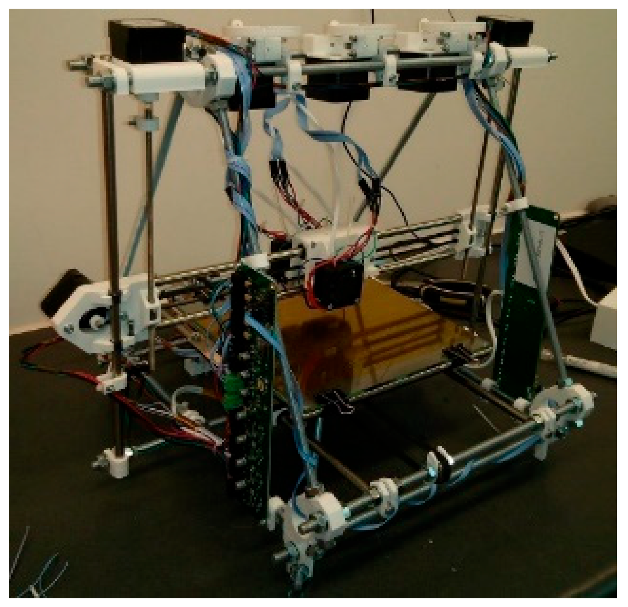
1]. Additive manufacturing is different to traditional subtractive manufacturing such as casting, forging, turning, milling, etc. It can manufacture complex geometries in a single location, unattainable through milling or other methods. Three-dimensional printing employs zero tooling and generates very little material waste compared with traditional subtractive machining. The RepRap 3D printer is an exemplar of an extrusion-based 3D printer in that it is capable of manufacturing some of its own structural (plastic) parts [
1], i.e., it is partially self-replicating (
Figure 1).
The RepRap 3D printer, like many 3D printing machines, is in essence a cartesian robot, and, indeed, the universal constructor has been envisaged as a cartesian robot assembler [
2]. The cartesian (or delta) form of a 3D printer may be converted into an assembling system by replacing the 3D printing nozzle with a three-degrees-of-freedom wrist. Self-replication of a 3D printer requires the ability to 3D print all the parts that constitute itself. All robotic machines are in essence kinematic configurations of feedback-controlled actuators, the 3D printer being a cartesian configuration of DC electric motors.
Our hypothesis is that if we can 3D print an electric motor, we have progressed significantly towards universal construction capabilities [
3]. A major leap towards such a universal constructor would be a demonstration that motors, electronics and sensors can be 3D printed within a single module of a self-assembling system. In situ manufacture of robotic systems requires the manufacture of electric motors, electronics and sensors. A complete motor system comprises a motor, gearing, sensors and controller. The universal constructor is a robotic system implying that realisation of the self-replicating machine requires self-construction of mechatronic components from feedstocks. Here, we shall consider only electric motors. We find that DC electric motors have yet to be 3D printed in their entirety until the work presented here.
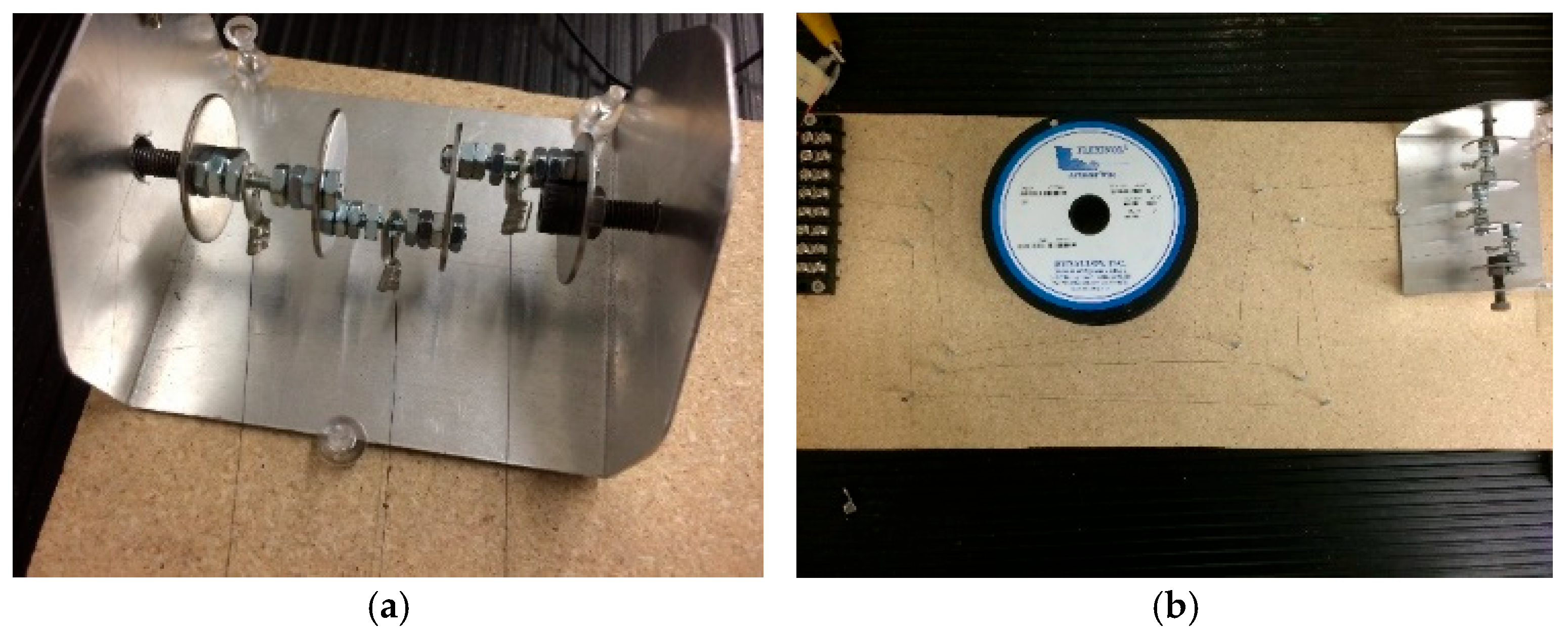
There are a multitude of options for creating 3D printed actuators. Despite the promise of smart materials as actuators, they do not provide the combination of stroke and torque magnitude that electric motors provide. We have illustrated this limitation of poor stroke and low frequency of actuation by smart materials in a rotational implementation of artificial muscles using NiTi shape memory alloy wire (
Figure 2). A simple three-SMA wire rotary motor was constructed, each wire mounted onto cams that were excited sequentially to turn the rotor (
Figure 2a). The lengths of the SMA wires had to be long enough to provide sufficient stroke to turn the rotor, limited by NiTi’s low strain capacity (
Figure 2b). Furthermore, thermal dissipation limited the rotary frequency to ~1 Hz.
One option to increase stroke and frequency is to drive an inflatable elastomer with a 3D printed micro-internal combustion engine [
4]. The complexity of this approach returns us to the electric motor. Electric motors are superior to both artificial and biological muscles due to their work capacity being multiplied by repeated rotational strokes rather than the single stroke of a linear motor [
5,
6].
All so-called 3D printed motors to date (in press releases rather than the referenced literature), when scrutinised, have not been fully 3D printed but only partially 3D printed. The closest to a 3D printed motor concept was a pancake DC motor with a dual PCB layer pancake rotor with etched copper coils and two pancake stators with a circumferential array of permanent magnets [
7]. It was constructed through conventional means but presented the idea of 3D printability. Structural aspects of the stator and rotor of an axial flux motor have been 3D printed before [
8], and printed pancake motor rotors are well established [
9]. Photolithographically printed copper wiring on the epoxy–glass laminate stator is parallel to the rotor, which carries alternating currents to generate rotor spin. Alternatively, the flat current winding is etched onto a flat armature of the plastic/ceramic circuit board [
10], e.g., as in Figure 13. Printing of spiral coils with rhomboidal turns avoids crowding at the inner radius of the armature [
11], e.g., as in Figure 14. A 3D printed version of a Halbach cylinder motor was based on a 3D printed structure in PLA (polylactic acid), which was tested at 5700 RPM, but the magnets and the coils were not 3D printed [
12]. This would be particularly crucial for a Halbach motor because a Halbach array comprises alternating main and transit permanent magnets arranged around the rotor. The magnetic configuration is crucial to the Halbach motor operation—the magnetic field is concentrated by almost twice as much on one side of the array and reduced to near-zero on the other. Similarly, a Halbach cylinder with a high power-to-volume density concentrates its magnetic field toward its centre through its arrangement of magnets to interact with its radial ferrite coils.
There are several approaches to 3D printing of bonded permanent magnets. Direct ink writing of an elastomeric silicone rubber composite with embedded ferromagnetic (NdFeB) microparticles and silica nanoparticles (for viscosity control) offers patterned magnetic properties by applying magnetic fields of ~2–3 T to the extrusion nozzle [
13]. Such patterning could be exploited for 3D morphological reconfigurability. Binder jetting has been employed to 3D print near-net-shape Nd
2Fe
14B permanent magnets [
14]. The binder jetting process uses an inkjet nozzle to deposit a polymer binder over a bed of NdFeB powder (average ~70 μm diameter) followed by application of a heat lamp to solidify the layer. Each 0.2 mm thick layer of magnetic powder and polymer is successively added to form the green part which is then cured at 100–150 °C for 4–6 h. The cured green part is then dip-coated with low viscosity urethane resin to fully saturate the porous magnet (46% resin by volume) and reduce its brittleness. Alternatively, infiltration by a low melting point eutectic alloy (Nd
3Cu
0.25Co
0.75 and Pr
3Cu
0.25Co
0.75) improves densification by 46% and improves the mechanical strength and intrinsic coercivity [
15].
2. Three-Dimensional Printing of Electric Motors
We present a fully 3D printed DC electric motor, which utilised several 3D printing methods and was subsequently assembled by hand. It is important to note that we are 3D printing a DC electric motor from suitable feedstock. A basic DC electric motor comprises a fixed stator within which spins the rotor controlled via a commutator assembly. Enamelled copper wire connects the commutator to the electrical power source, a commutator/wire brush assembly cyclically reverses the supply current to the rotor, a stator mounts permanent magnets which provide magnetic flux without power consumption, and a coiled copper wire wound around a soft ferromagnetic core armature acts as an electromagnet that consumes power. The interaction between the two magnetic fields generates a Lorenz torque on the rotor. The stationary brushes connect to the commutator switches and reverse the coil current every half revolution through slip rings. In the brushless DC motor, the permanent magnets are in the rotor and the coils are wound around the stator. The use of ferrites over rare earth permanent magnets results in a larger motor for the same torque.
Energy losses in the soft magnetic material are due to the following: (i) hysteresis loss which can be reduced by low coercivity; (ii) eddy current loss which can be reduced by low electrical conductivity; and (iii) anomalous losses which can be reduced by using homogeneous material to permit magnetic domain migration. It is essential that hysteresis in the electromagnet is minimised to ensure that no magnetic field is retained on removal and reversal of the electric current. This requires soft magnetic materials for the magnetic core—ferromagnetic material such as soft iron or ferrites. Iron’s electrical conductivity makes it susceptible to eddy currents and heating losses. To suppress eddy currents, the core may be constructed from thin insulated sheets forming a laminated core, e.g., sequences of iron layers which are surface-oxidised and sandwiched to limit eddy current transmission. Alternatively, micron-sized iron powder may be embedded in an insulating matrix—this minimises eddy currents while magnetic field generation and magnetic threading is maximised.
We adopted the DC electric motor as our 3D printed motor model because all other motors are derived from it through reconfigurations of the same functional components. For example, synchronous AC motors generate torque using either permanent magnets, magnetic reluctance or a combination of these (they are generally more efficient than AC induction motors when operated at constant speed). For most of our extrusion-based 3D printing, we used an Anet A8 3D printer running at 190 °C based on the Prusa i3 with a 0.4 mm nozzle and 0.1–0.2 mm position resolution. Our 3D CAD models were built using PTC Creo 4.0 CAD software, which were converted to STL format for slicing into layers using Cura. We used a 15–18 V DC power supply for our 3D printed motors.
2.1. Motor Testing Apparatus
Our motor test apparatus evolved over time. For our early tests, which focused on 3D printing rotors, we adopted a simple but effective apparatus that involved mounting the rotors within a simple stator frame with mounted rare earth magnets. The shaft was connected directly to the motor holder of an off-the-shelf MiniPro R/C Car Inertia Motor V2 Dynamometer (
Figure 3).
As the project progressed, we adopted an increasingly sophisticated test apparatus. The dynamometer required direct mechanical mating of the motor shaft, which was inconvenient when we worked with dual excitation and pancake motors. We replaced it with a B+K Precision DC Regulated Power Supply 1671A (0–30 V and 0–5 A range) with a voltage/current resolution of 0.1 V and 0.01 A, respectively, an AstroAI DM6000AR Multimeter (6000 counts) with a voltage/current resolution of 5 mV at 30 V and 0.5 mA at 3 A, respectively, for more precise control (
Figure 4a) and, for the fully printed DC motor, we supplemented this setup with a Siglent SDS 1104X-E digital oscilloscope (
Figure 4b).
We used an automatic wire winding system to wind high turn-number coils around stator poles that was implemented using a custom-modified Sherline 4410 mini-lathe (
Figure 5).
2.2. Three-Dimensional Printing of Soft Magnets for Rotors
Our earliest efforts concentrated on the soft magnetic rotor, which was 3D printed with 8 slots to accommodate four-pole rotor windings of 95 turns/pole of 30 MAG copper wire. A 3D printed PLA commutator was mounted with four sets of copper sheets, with two brushes of 20 Ga bare copper wire. For the wire-wound rotor, the commonest soft magnetic material is silicon steel (Fe-3% Si). Typically, it reduces the incidence of eddy currents and is either laminated with insulation material such as polymer or silicon steel particles are embedded with high loading in a polymer matrix. Binder jetting of magnetically soft silicon steel (Fe
91Si
9) yields potentially higher magnetic permeability than powder metallurgy of soft magnetic composite powders [
16]. Other possibilities include new soft magnetic materials with low coercivity/high electrical resistivity, such as coarse particles of a multicomponent alloy (Fe
32.6-Ni
27.7-Co
27.7-Ta
5.0-Al
7.0) dispersed within a ferromagnetic matrix [
17].
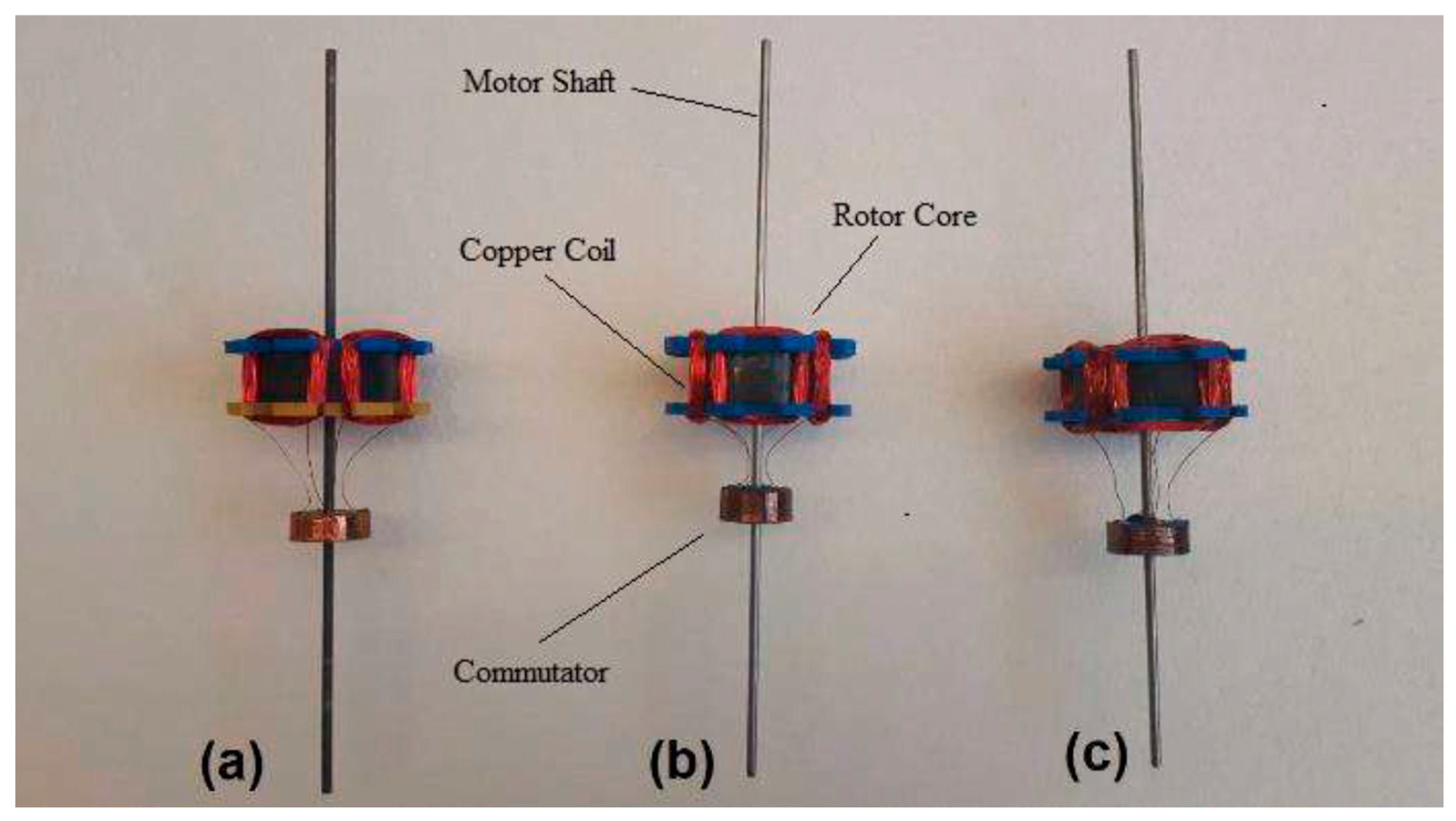
Our first 3D printed rotor cores were printed in Fe-3Si and Fe-6.5Si, with a 40 mm diameter by 14 mm length by NRC-Boucherville (
Figure 6b and
6c, respectively). These comprised 50% Fe-Si particles in 50% PLA matrix by volume. We 3D printed motor cores of commercial off-the-shelf ProtoPasta
TM (
http://www.proto-pasta.com) magnetic PLA with the same geometry through extrusion (
Figure 6a). The ProtoPasta
TM filament was magnetic iron-filled composite PLA that comprised 50% iron particles of <250 μm diameter in 50% PLA by weight, i.e., considerably lighter than loading by volume.
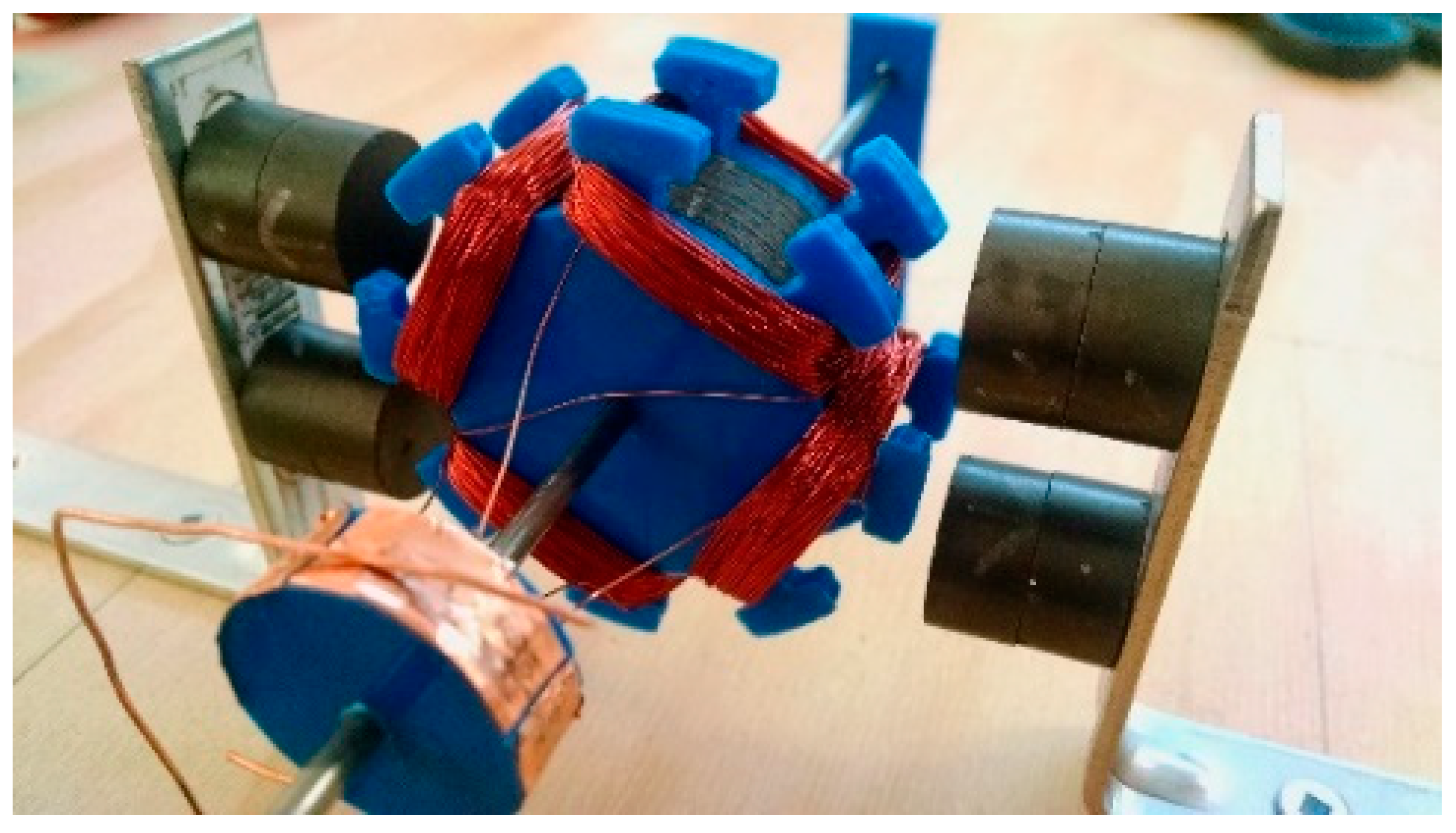
The 3D printed motor cores were wound with copper windings for the rotor and mounted into a stator structure to accommodate embedded permanent magnets (
Figure 7). They were tested within a two-pole stator assembly using a dynamometer for measuring voltage, current, RPM, power and torque output.
The bonded Fe-6.5%Si steel-impregnated PLA gave superior performance over the traditional bonded Fe-3%Si steel-impregnated PLA. However, the performance results clearly show that the ProtoPastaTM magnetic PLA rotor offers superior performance in terms of RPM and torque output than the silicon steel rotors (
Figure 8). We attribute this to the higher weight of the Fe-Si particle-impregnated rotors (136 g) compared to the ProtoPasta
TM rotors (71 g). The moments of inertia of the identically shaped cylindrical rotors are dependent on the masses only, so the heavier rotor has higher inertia. The increased inertia of the 50% steel particle rotor by volume was not offset by the increased magnetically induced torque, yielding a reduction in rotation speed.
Future work might search if there an optimal cross-over between the two bookend conditions of 50:50 by mass/volume by systematically reducing the iron from the 50% by volume condition. We did not conduct such an investigation.
2.3. Three-Dimensional Printing of Dual Excitation Motors
Reluctance motors have a rotating magnetic field around the stator concentrated at the poles (which are magnetically isolated from each other) which drives the rotation of a soft magnetic rotor due to magnetic reluctance. We experimented with ProtoPasta
TM to 3D print a variable reluctance motor (
Figure 9) but we did not benchmark it. Our interest was to explore motors without permanent magnets, but we anticipated that the multi-coil design of the reluctance motor would present subsequent challenges for 3D printing.
Given the demonstrable success with ProtoPasta
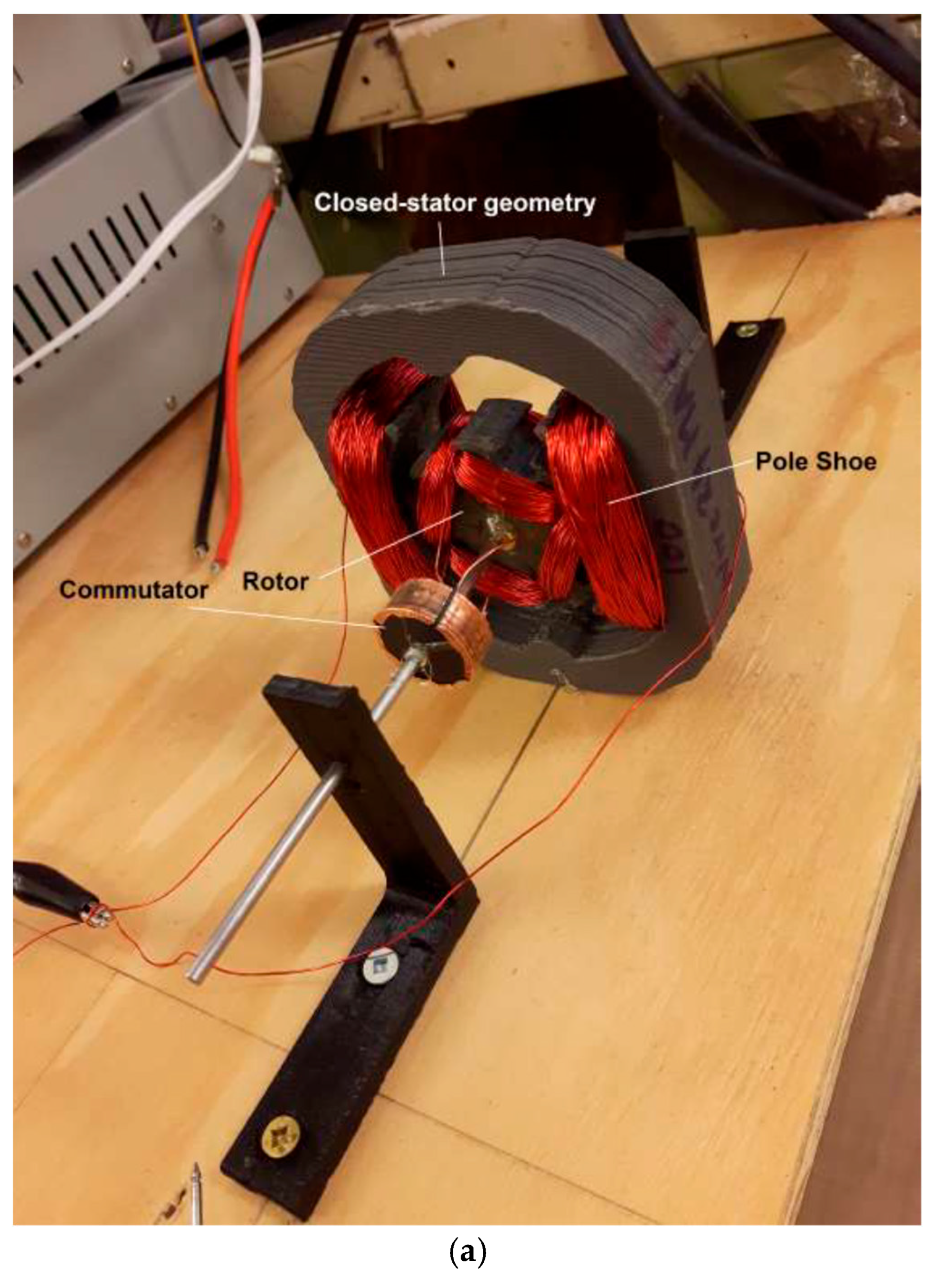
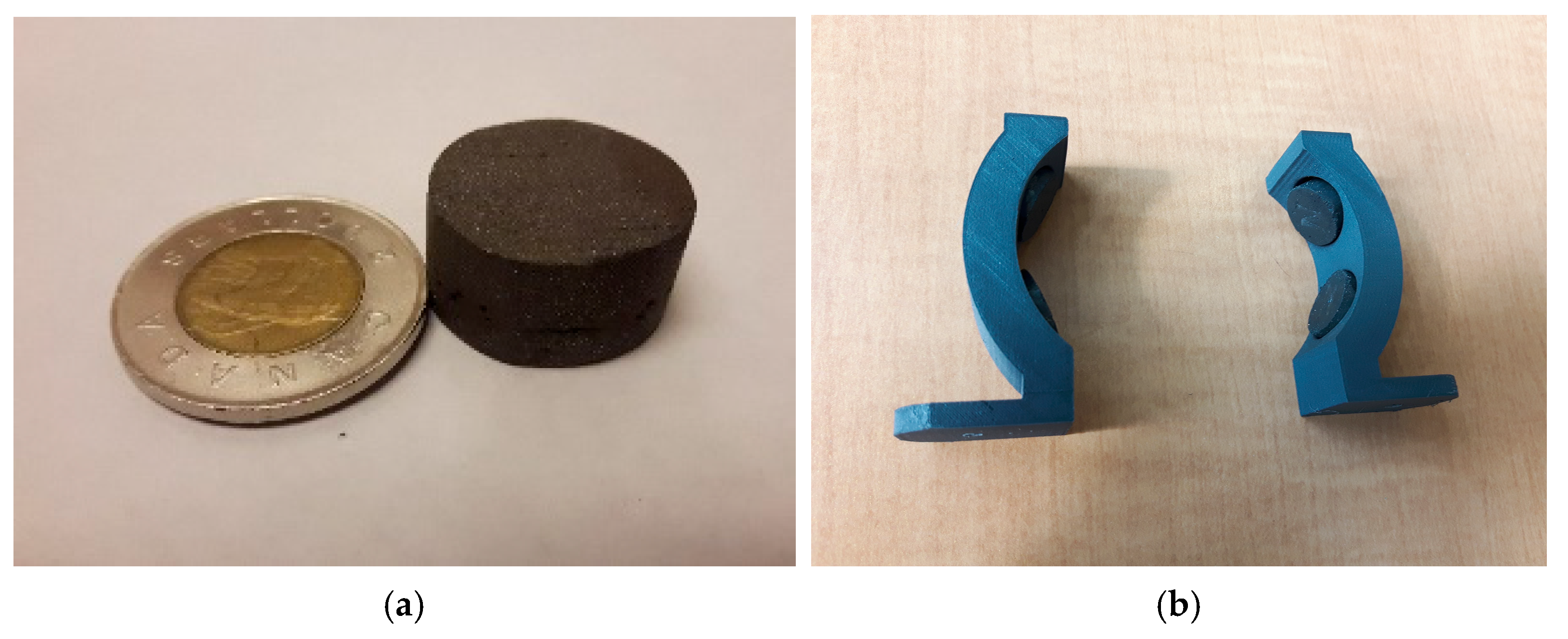
TM, we investigated the dual-excited DC motor using magnetic PLA material for both the rotor and stator magnets. Dual excitation motors eliminate permanent magnets by adopting separately excited coils on electromagnetic poles and the electromagnetic rotor, but they still require brushes to transmit energy to the rotor. An open geometry stator was insufficiently powerful to generate torque, so a closed magnetic loop stator was printed with ProtoPasta
TM (
Figure 10a,b). The rotor was wound with 70 turns/pole and the stator was wound with 100 turns/pole using an automatic wire winding system. The only non-3D printed parts were the steel motor shafts and the copper coils. We also set up the 3D printed dual excitation motor with a 3D printed PLA step-down gear to demonstrate closing of a hinged panel (as a proxy for self-deployment of structural panels) (
Figure 10c).
2.4. Three-Dimensional Printing of Permanent Magnets for Stators
We explored the adoption of 3D printed permanent magnets for the DC motor stator. The cheapest permanent magnetic material is ferrite, in which dominant Fe
2O
3 particles are supplemented with SrCO
3, BaCO
3 or Co additives and subjected to powder metallurgy. Our 3D printed electric motor used 3D printed high-strength rare earth element (30% Nd–66.8% Fe–1.0% B–0.4% Al–0.8% Nb–1% Dy) permanent magnets manufactured by Oak Ridge National Laboratory (
Figure 11. Oak Ridge National Laboratories’ big area additive manufacturing (BAAM) facility uses melt extrusion of thermoplastic composite mounted onto a gantry system for unbounded size [
18]. Extrusion from pellets of 65% NdFeB plate-shaped powder of 20–200 μm diameter with a 35% nylon–12 binder by volume at 285 °C (lower than the NdFeB Curie temperature of 360 °C) onto a heated aluminium bed at 95 °C increased the magnetic density and eliminated the porosity impregnation step. The 3D printed NdFeB permanent magnets manufactured using BAAM outperform conventional injection-moulded magnets with a remanence of 0.51 T and ultimate tensile strength of 6.60 MPa. High magnetic alignment of NdFeB particles in a polymer binder is enhanced by an applied magnetic field on the binder during its transition from high elasticity to lower viscosity at <100 °C [
19]. BAAM was used to extrude a high NdFeB loading fraction of 70% in 30% nylon binder into 3D printed permanent magnets with superior properties (ultimate tensile strength of 12.6 MPa and remanence of 0.58 T), which was demonstrated in a 12 V DC electric motor assembly (not 3D printed) [
20]. A silica ceramic coating provided thermal stability to oxidation at a high temperature. Our permanent magnets were similarly 3D printed by Oak Ridge using the same BAAM technology and specifications (
Figure 11a). These were used in several motor configurations, including the fully 3D printed DC motor stator (
Figure 11b).
Magnetisation of a permanent magnet involves applying an external magnetic field to saturation, which is then slightly demagnetised for stabilisation. The external field is generated by a capacitor bank to yield a very short current pulse through a coil. After printing, our rare earth magnets were exposed to a short current pulse to generate an applied magnetic field 4–5 times their coercive force through a magnetising coil (
Table 1):
2.5. Challenge of 3D Printing Wire Coils
The wiring and wire coils were the most challenging to address with 3D printing technologies. We briefly investigated liquid metals such as the gallium-based alloy GaIn (melting point 15.5 °C) that may be 3D printed as pressurised ink through a nozzle into highly conductive tracks, with a conductivity of 3.4 × 10
6 S/m within silicone channels [
21]. The problem of leakage at room temperature was considered too problematic. Metal wire may be embedded into a 3D printed plastic substrate by heating the wire with a thermal probe that melts the plastic only locally [
22]. This was unnecessary as we printed the DC rotor with wire grooves. To investigate the 3D printing of wire coils, we used a pancake (axial flux) motor configuration [
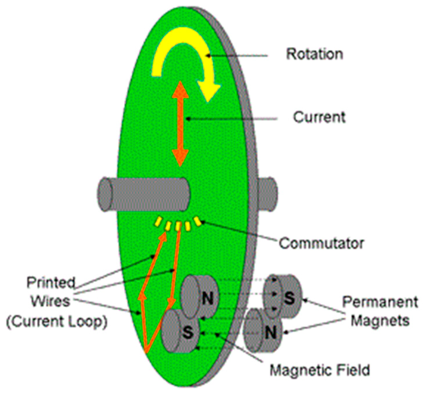
23] (
Figure 12).
We adopted a stator with embedded permanent magnets on either side of a disk-shaped double-sided PCB rotor [
24,
25]. We tested several methods for printing the coil patterns on the rotor. Printing spiral coils with rhomboidal turns avoids crowding at the inner radius of the armature [
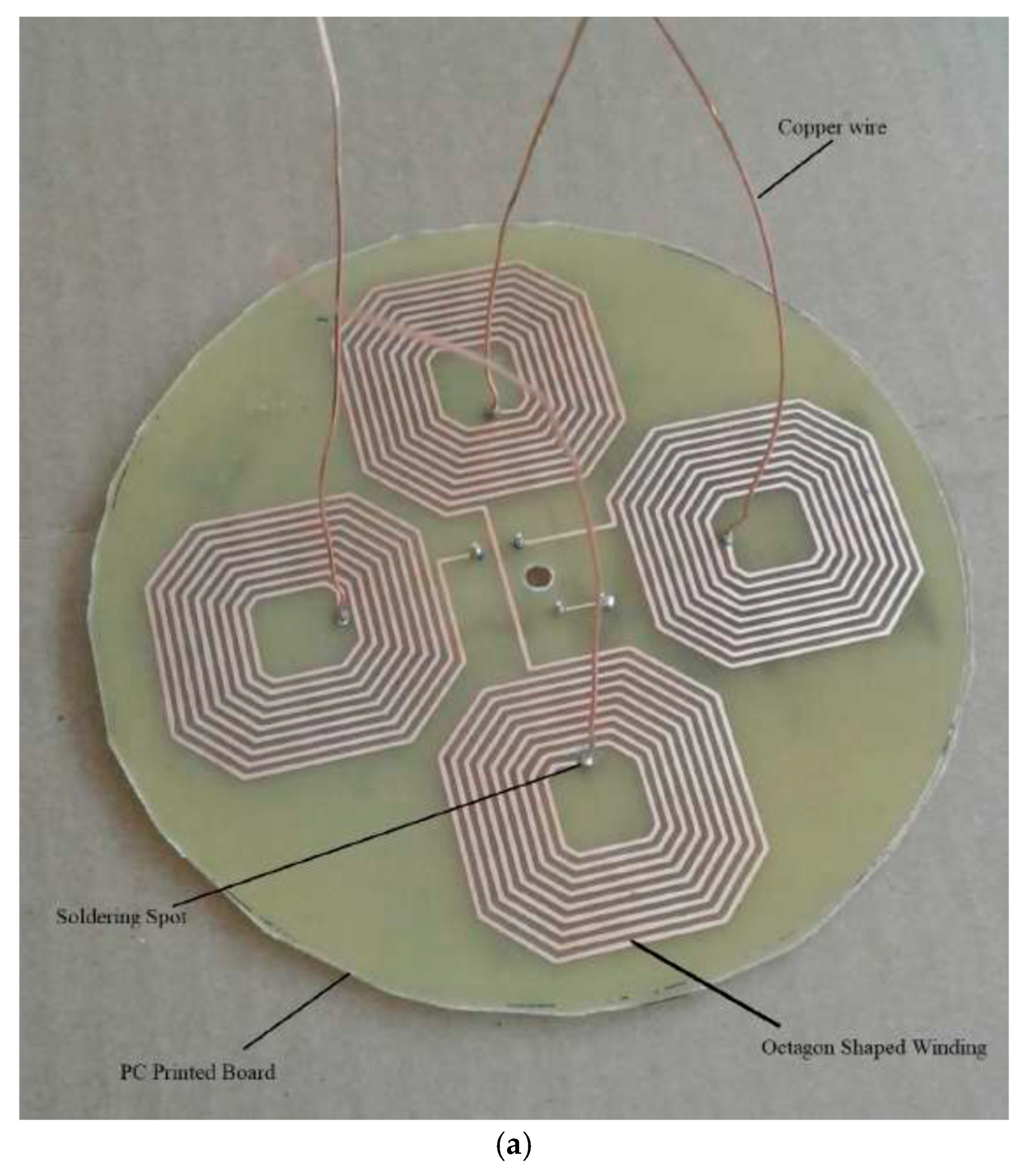
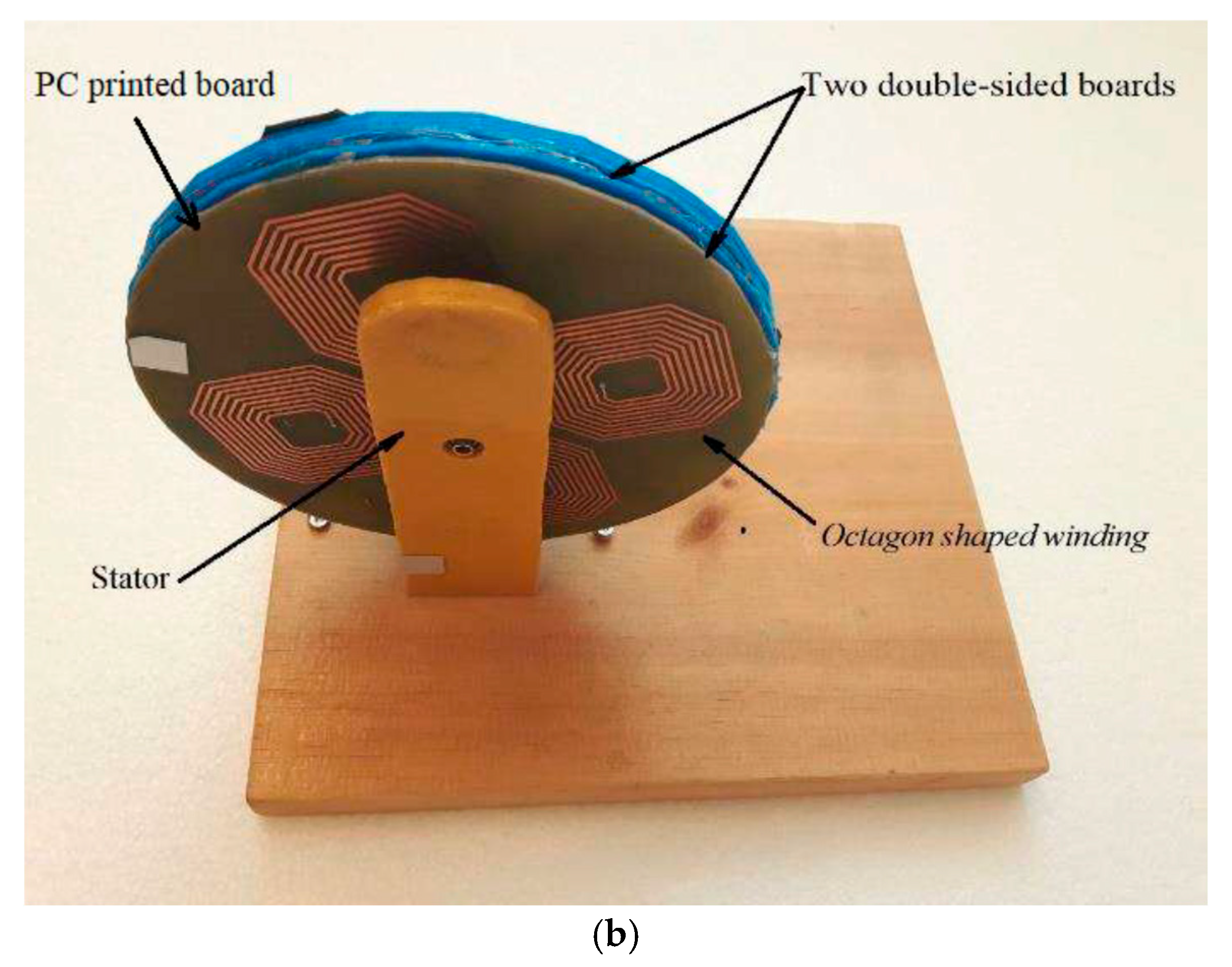
10]. This is more difficult to manufacture. We initially etched double-sided copper-clad PCBs with a simpler geometry of octagonal spiralling coils (
Figure 13). A 600 dpi laser printer was used to print the coil schematic onto the transparent film of a 416-T mask. Photoresist MG 416-X was used to treat the PCB and then was exposed to UV light through the mask. The board was immersed into MG Chemical developer solution, which removed the UV-exposed resist. The exposed copper was removed by immersion in MG 415 etchant, leaving the armature winding pattern.
The number of spirals per layer equates to the number of rotor poles P. Each octagon winding comprises nine turns with traces and a spacing of 1 mm, giving 18 turns/pole. A single double-sided and two double-sided PCBs were separated by 3D printed polymer spacing. They were mounted into a stator with embedded off-the-shelf permanent magnets, yielding an increase in performance from 500 RPM to 700 RPM. We anticipated that this photolithographic approach would be difficult to adapt to a traditional DC motor configuration with orthogonal wiring.
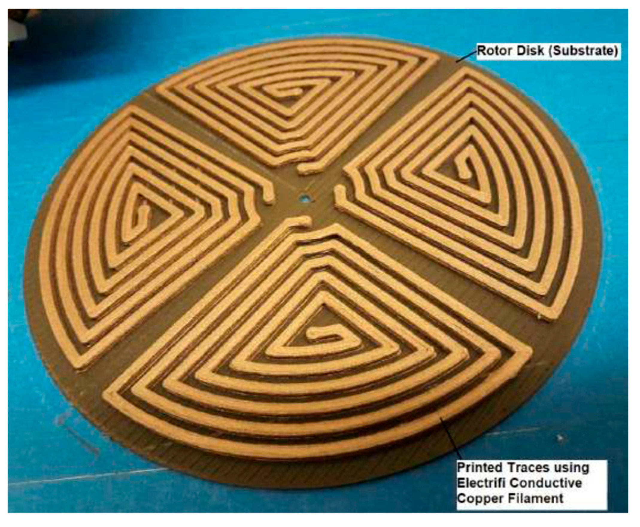
Our next approach was to 3D print a pancake rotor using two filaments deployed from a single printer head. The substrate was printed using the ProtoPasta
TM and cooled followed by deposition of Electrifi conductive copper filament with a resistivity of 0.006 Ω.cm. The copper filament comprised copper-impregnated PLA plastic to print conductive tracks (
Figure 14). Printing the copper-impregnated filament required reducing the print speed to 15 mm/s and maintaining a minimum 0.2 mm gap between the nozzle and the printing surface. A more efficient spiral coil geometry was printed because the rotor coils lie parallel to the rotor disk.
Such materials are suited to electrical conduction of data at low voltages/currents but power electronics impose high voltages/currents. On connecting to a DC power supply to test the conductivity of the tracks, an applied voltage of 3.4 V generated hot spots on contact due to an increased resistance of 17 Ω with 200 mA currents. Such conductive filaments are unsuited to electrical power applications such as motors. Our motor runs at 12 V, which would melt the polymer matrix. This limitation applies to all current conductive polymers due to their poor current-carrying capacity, and they are suitable only for low-voltage data electronics. The wires and wire coils of motors must be made of conductive metals. There is the further problem of thermal sintering of copper-impregnated pastes without melting the substrate. One approach would be to create microchannels of silicone, which is tolerant of significant temperatures up to ~300 °C. Three-dimensional printing of microfluidic systems requires submillimetre scale manufacture of silicone for the enclosing channels [
26]. Silicone moulds and templates may be 3D printed using SLA in the shape of microchannels with sub-100 nm features. The microchannels may then be filled with room temperature liquid metals such as mercury or gallium. However, we considered this approach to be too complex to manufacture. An alternative approach is to print metal directly onto a substrate: for high precision, fine channels may be etched to guide the metal tracks with subsequent milling. Metal conductive tracks are commonly 3D printed using nanoparticle conductive inks. Laser annealing is necessary to create fully metallic conductive tracks on a substrate. This has been the approach for 3D printing of electronic devices including conductive wiring, such as conductive strips on conformal antennae. The difficulty with these approaches is lifting such conductive tracks to wrap them around a DC motor in the transverse direction to rotor printing.
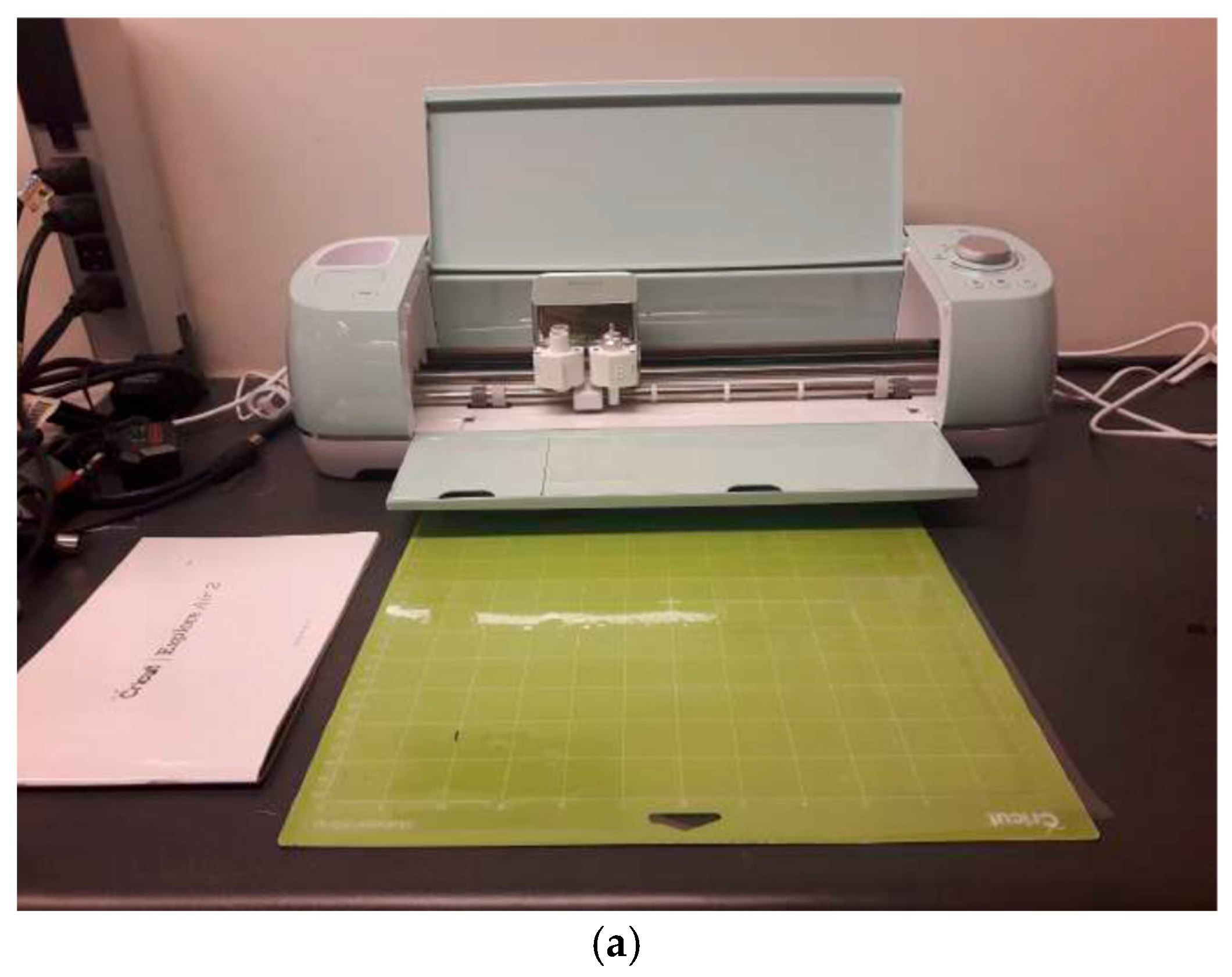
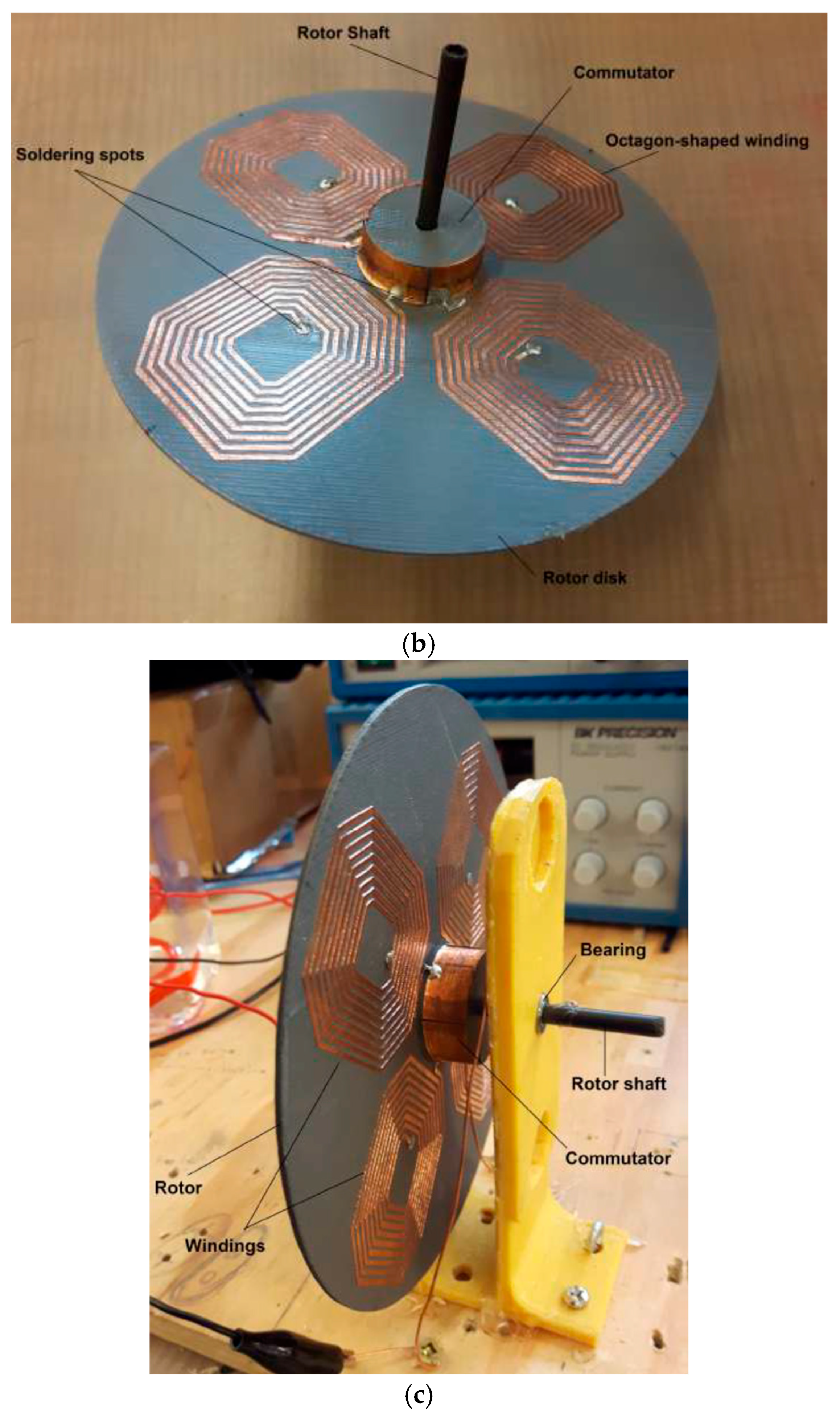
Metal conductors were required, so we adopted a variant on laminated object manufacture (LOM) for the wire and wire coils of the motor (
Figure 15). A layer of metal foil with thin adhesive backing acting as an insulating layer (in this case, copper, but this could be substituted with aluminium foil) was applied to a worktop and rolled flat. A Cricut Explore Air 2 cutting machine was programmed with the wire coil design to cut a 0.0762 mm layer of copper sheet into the desired shape (
Figure 15a). The excess copper was removed by hand, leaving only the desired shaped 2D layer. The four-quadrant design minimises the number of soldering points to four, compared with a traditional radial pattern of pancake motors which requires not far short of 100 solder points depending on the size of the rotor cross-section. The copper winding trace was taped onto both sides of the 3D printed pancake rotor of magnetic PLA and mounted into a stator assembly with embedded permanent magnets for testing (
Figure 15b,c). Its performance was similar to the PCB motor with photolithographically printed copper, as expected.
A mounted Hall effect sensor measured the back EMF from the rotor spin to permit the control electronics to synchronise pulsing of the coils (neither the permanent magnets nor the Hall sensor were 3D printed). In LOM, further adhesive layers are added and heated with the hot roller to bond the layers together to build up the 3D part. In our case, we required only a single layer of foil to form the conducting ribbons while retaining their thin adhesive layer. This approach is consistent with 3D fabrication of electronic components such as resistors, capacitors and inductors with multiple layers of conductive strips.
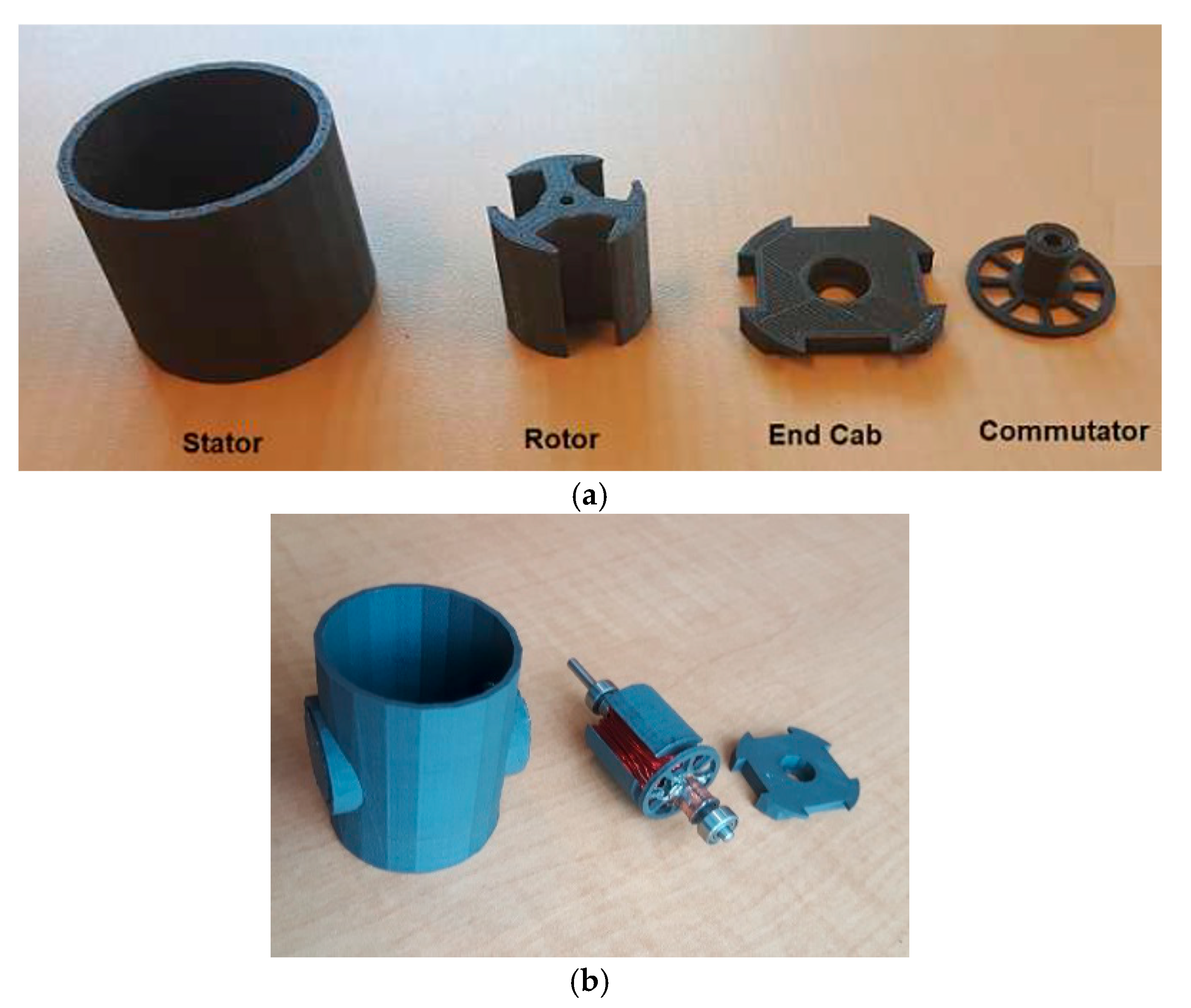
2.6. Assembly of Fully 3D Printed DC Motor
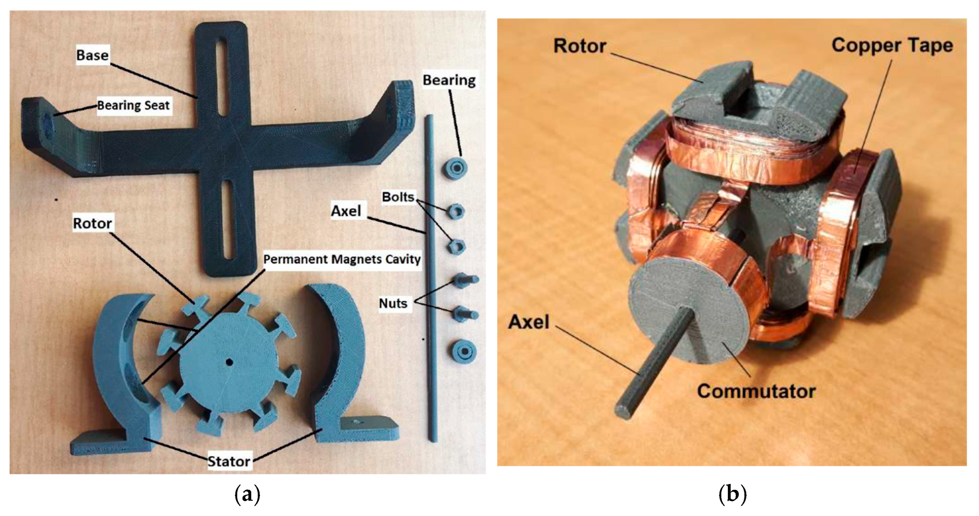
We return to the fully 3D printed DC electric motor configuration to combine all the earlier elements. The basic structural components (bracket), motor shaft, bearings and bolts were 3D printed using PLA (
Figure 16a). The stator structure that holds the Oak Ridge-printed permanent magnets and the rotor were printed using ProtoPasta
TM magnetic PLA (
Figure 16a). Four 3D printed NdFeB bonded permanent magnets from Oak Ridge National Laboratory were embedded into the stator. Once again, the chief problem was the copper coils. If the ribbons were too thin, they could not be manually wound around the rotor without breaking. Hence, we printed wider ribbons of 5 mm width which were more durable, enabling them to be wrapped around the rotor with 17 turns/pole after coating with a silicone conformal coating for durable insulation (
Figure 16b).
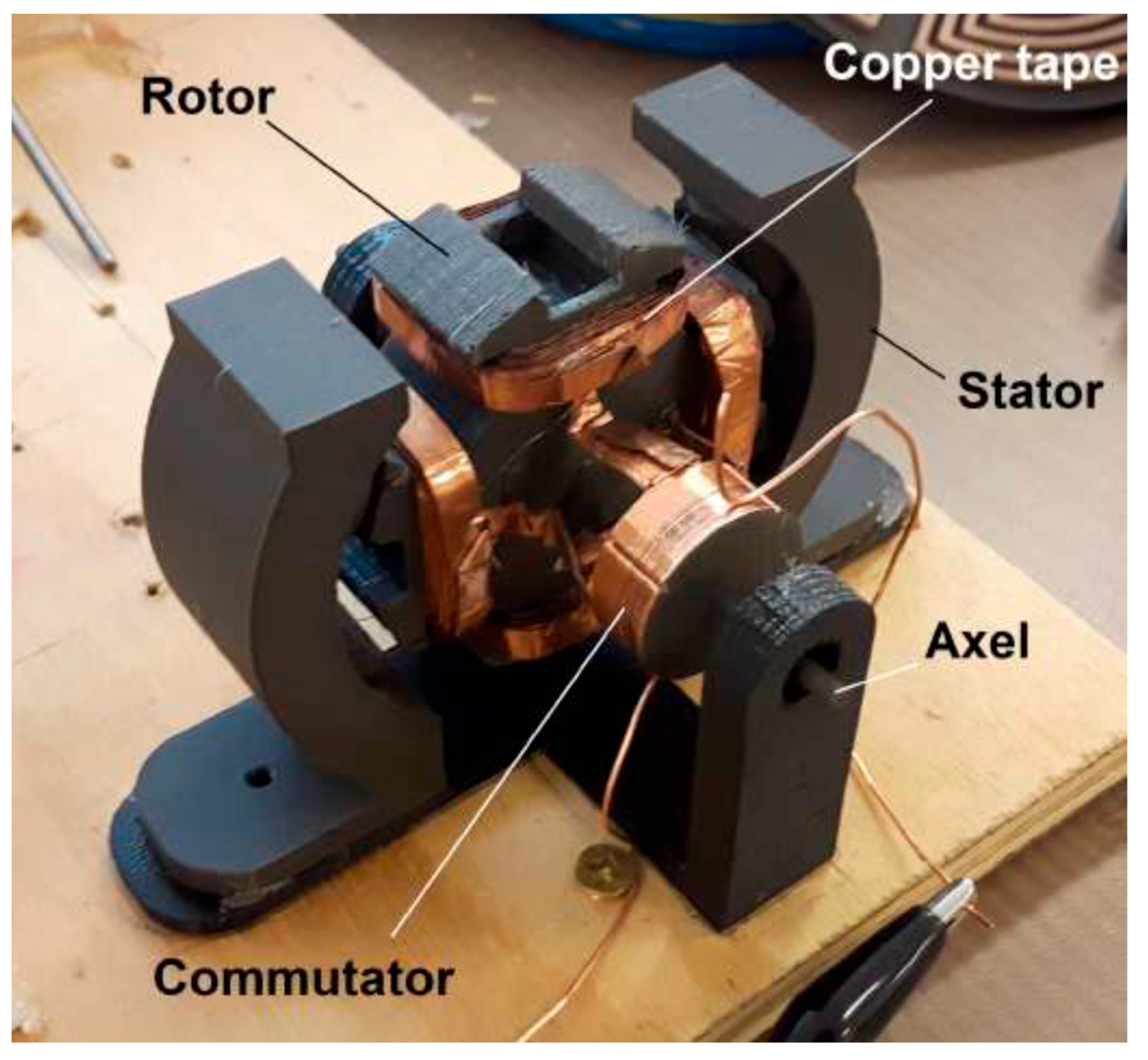
The entire 3D printed DC motor was assembled manually (
Figure 17).
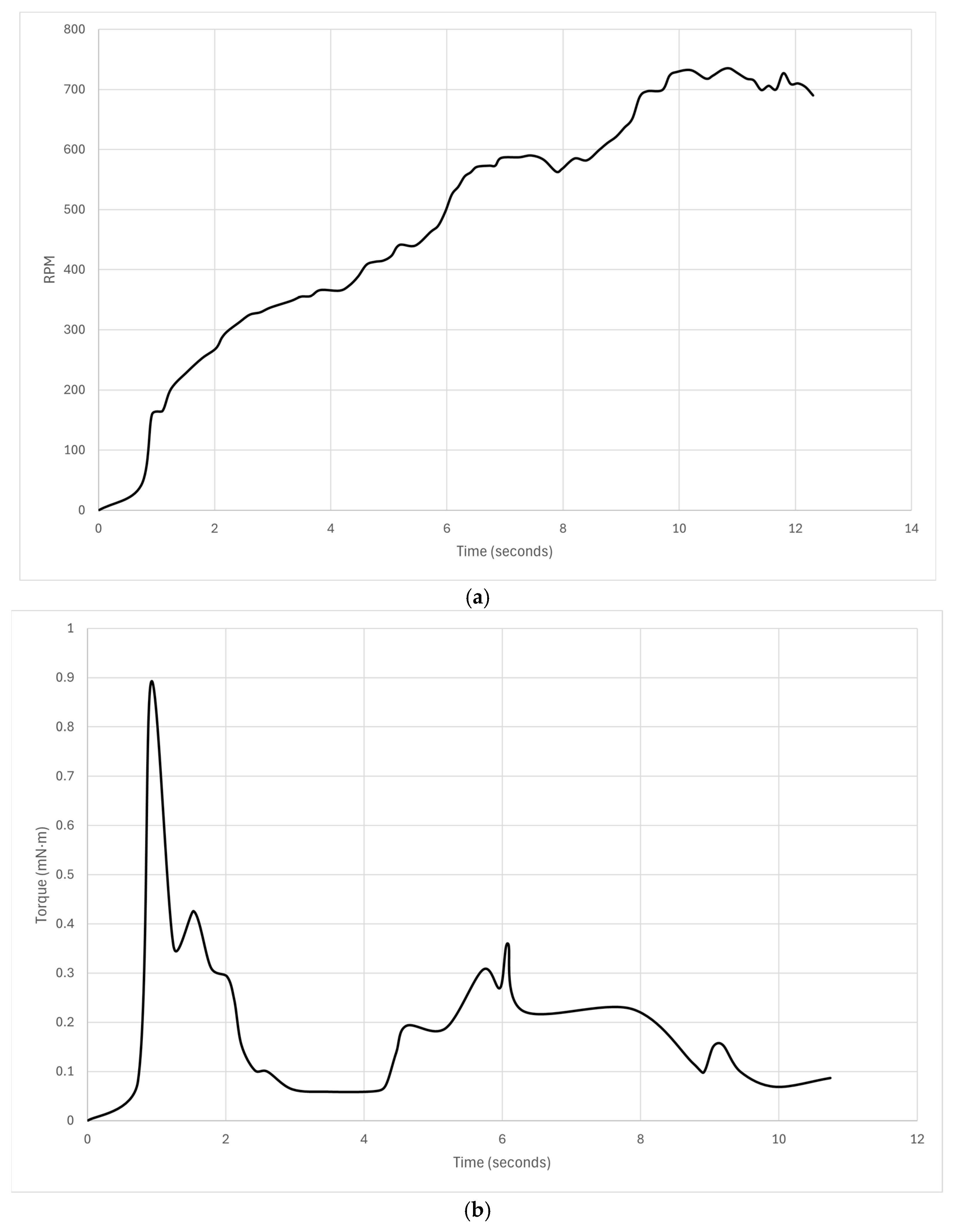
The fully 3D printed DC motor operated successfully, although its performance in terms of both angular speed and torque output (no-load) was significantly inferior to any commercial motor of similar size due to the minimal number of wiring turns (
Figure 18)–see the
Supplementary Material for a video demonstration. The RPM plateaued at a sedentary 700 RPM, but the torque curve clearly demonstrates a high degree of stiction before settling at a very low 0.1–0.2 Nm no-load torque output.
This was a successful proof-of-concept for a 3D printed motor but too inferior for practical utility. The few-turn wire coils were the culprit for the poor performance, as shown below in subsequent experiments. This follows from basic motor theory:
where
= motor torque constant, n = number of windings, A = coil section area and B = magnetic field strength. Although fully 3D printed, it required three different 3D printing techniques and required sophisticated assembly by hand. There have been attempts to minimise assembly operations for electrical machines. A functional soft magnetic core solenoid of stacked plates was printed from a single multi-material FDM printer extruding filaments and pellets [
27]. Each plate comprised alternating spiral conductors from a central soft iron core separated by insulating plates. The conductive spiral was formed by introducing conductive connections through the insulator between the stacked plates. Three materials were printed—pure PLA for insulating structures, PLA impregnated with copper particles for electrical conductors and PLA or nylon impregnated with Fe or FeSiAl particles, respectively, for soft magnetic cores. The advantage of this approach is that it exploits a single 3D printer to minimise assembly, but the copper-impregnated conductive elements were limited to 60 mA, so the maximum field generable was ~1 G, which is very low. The current trade-off is between motor performance, which requires the adoption of different 3D printing methods for different materials, against the complexity of assembly. One can envisage adopting a single FDM approach, in which ProtoPasta
TM was adopted for magnetic elements and copper-impregnated PLA for conductive elements of an entirely polymer-based motor, but such a motor would have such a poor performance that it is questionable whether it could function at all.
2.7. Benchmarking a Partially 3D Printed Motor
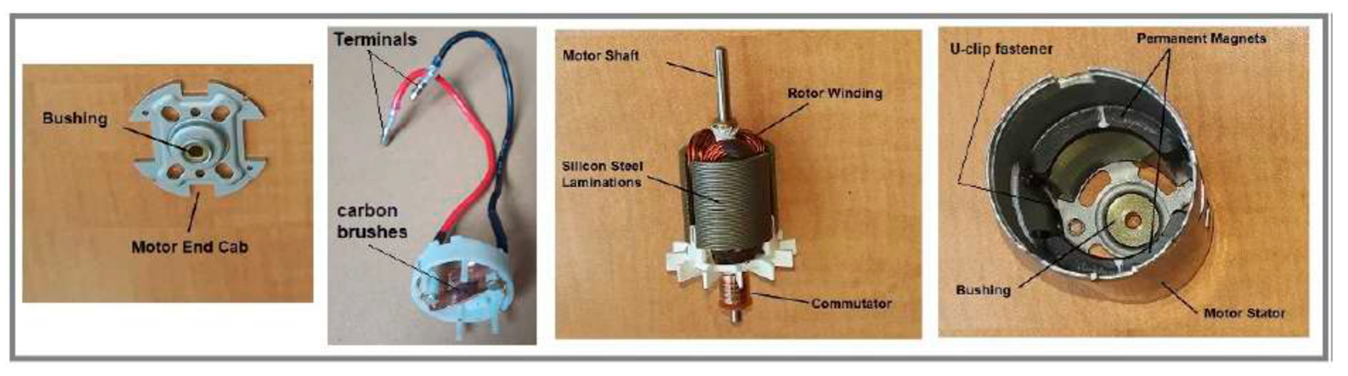
It was not possible to make a direct comparison of our fully 3D-printed DC motor with a comparable commercial motor, even if one could be sourced with a similar geometry, as there would be too many variables to perform meaningful analysis. We alluded to the small number of coil turns around the rotor presenting a major limitation in the fully 3D printed motor. One way this could be circumvented is to supplement 3D printing with wire drawing through a series of dies. The wire may be copper or aluminium. Indeed, aluminium wiring is common in motors, generators and transformers. Insulation may be implemented using coating with fused silica powder and thermal curing (enamelling), wrapping with fiberglass or silicone polymer tape, or extrusion of silicone polymer or fused silica powder around the wire as it is drawn. Wire drawing is similar to extrusion except that it involves pulling rather than pushing through an orifice. It is not inconceivable that an extrusion nozzle of a 3D printer may be adapted to wire drawing. To compromise, we benchmarked a partially 3D printed motor (eliminating the problem of matching copper coils) against an off-the-shelf Dynamite DYN 1171 brushed permanent magnet DC motor, which was disassembled to extract its physical parameters (
Figure 19). This allowed us to determine the performance of the partially 3D printed motor on the basis of its 3D printed magnets, both hard and soft, by eliminating the wiring factor.
This off-the-shelf motor was used as a reference to 3D print versions from ProtoPasta
TM magnetic PLA that were as similar as possible (
Figure 20a)—this required high resolution 3D printing at a 0.15 mm setting with 100% infill at low printing speed for the 3D printed version. The same number of wire turns, and copper coil gauge and core dimensions were adopted for the 3D printed version (
Figure 20b).
The armature employed lap winding, that ensures that the number of parallel conducting paths and poles are the same. The same wiring configuration was adopted for the 3D printed version—wiring was not 3D printed but the same gauge wire was used (32 AWG) (
Figure 21). The test equipment was the dynamometer, and voltage and current sensors. Two versions were tested—a partially 3D printed motor (3D printed rotor only) using the off-the shelf stator and a “fully” 3D printed motor using the Oak Ridge permanent magnets (but with conventional coils).
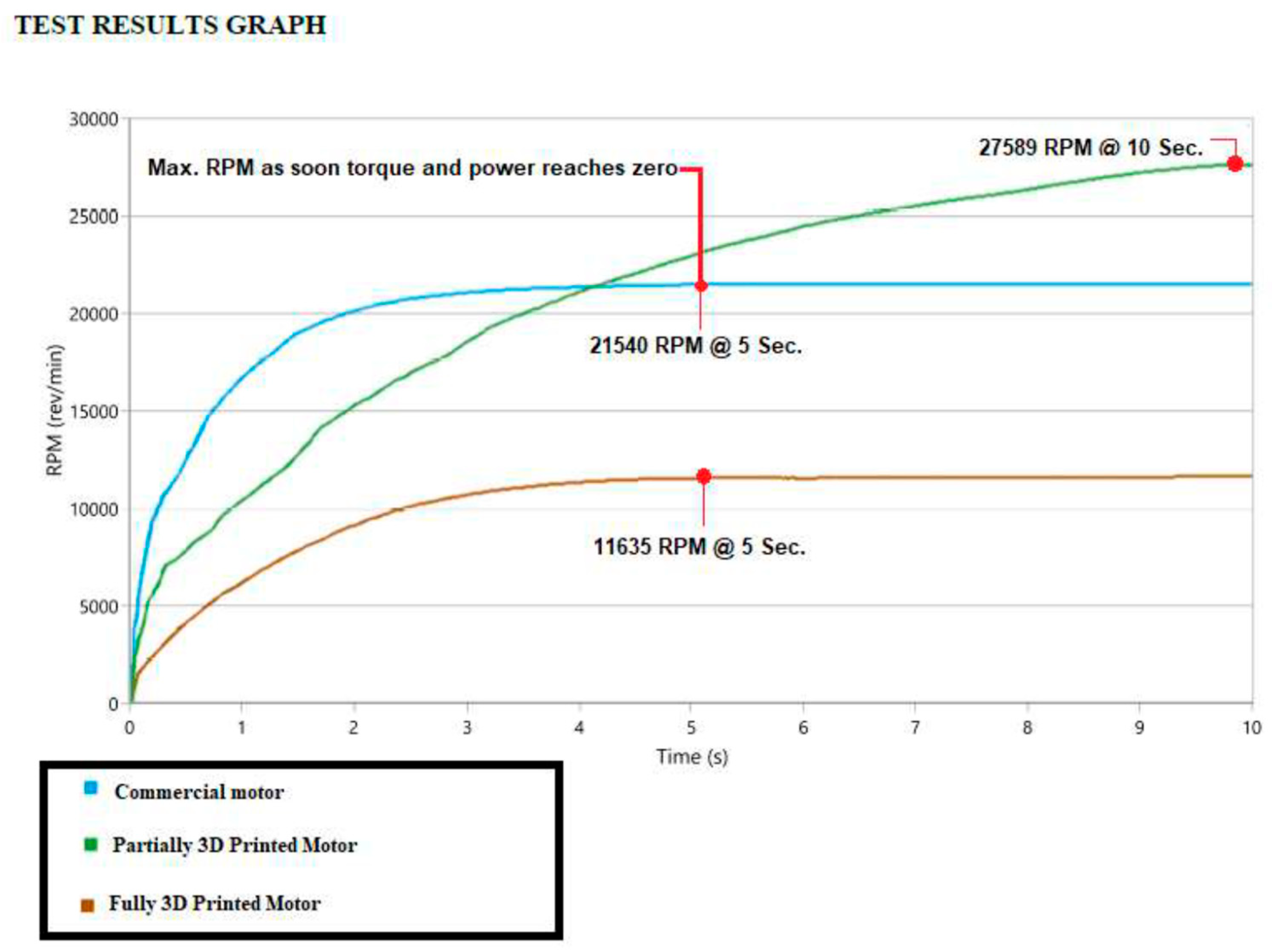
There were three sets of motors tested: (i) a commercial off-the-shelf motor as the benchmark; (ii) a partially 3D printed motor in which only the rotor was 3D printed from magnetic iron PLA wound with conventional wire coils mounted into the commercial motor’s stator; (iii) a “fully” 3D printed motor in which the rotor was 3D printed from magnetic iron PLA wound with conventional wire coils mounted into a 3D printed stator embedded with the 3D printed rare earth magnets from Oak Ridge. The 3D printed motor using the Oak Ridge magnets and ProtoPasta rotor yielded the same characteristic form (unlike the 3D printed rotor-only motor) as the commercial motor, but with a diminished performance of 54% of its RPM (
Figure 22). The difference between the two 3D printed motors is interesting—the 3D printed rare earth magnets yield a stabilised (though diminished) performance compared to the commercial stator magnets, but the 3D printed magnetic PLA rotor showed enhanced RPM output over the commercial product. It is important to note that we were proving a concept—that 3D printed motors can be constructed, rather than optimising their performance against a commercial grade production motor.
2.8. Summary
We have shown (i) a successful proof of concept of a 3D printed electric motor; (ii) that more development, however, is required for a practical 3D printed motor; and (iii) that both theory and an experiment involving conventional wire coils contrasted with LOM-derived wire coils demonstrate that the poor performance of the 3D printed motor lies in the number of coil turns. Furthermore, the 3D printed ORNL rare earth stator magnets were inferior to the conventional magnets of the commercial motor.
3. Future Developments
Our approach to 3D printing the DC motor relied on multiple 3D printing approaches followed by manual assembly of the motor. The next stage would be to do the following: (i) merge 3D printing technologies of different materials into a single 3D printing mechanism; (ii) incorporate non-3D printing where appropriate, such as wire extrusion/drawing; and (iii) eliminate manual assembly with integrated manufacture and automated self-assembly. Three-dimensional printing of multi-material parts represents a considerable challenge in integrating 3D printing into a more general fabrication process.
Different 3D printing methods are appropriate for different engineering materials. In general, polymers such as ABS, PEEK, etc., are printed through fused deposition modelling (except for photosensitive resins which are printed using ultraviolet stereolithography). Metals such as steels, titanium alloys, aluminium alloys, etc., may be printed using selective laser sintering/melting and electron beam additive manufacturing (the latter is restricted to metals only). Ceramics are typically processed as particles within a matrix material, but they present challenges for 3D printing. There are several strategies that might be employed to implement multi-material fabrication using different 3D printing methods [
28]. In extrusion and direct ink writing, different materials may be pre-mixed into a blend for extrusion. Stereolithography may implement multiple vats of different photopolymers on a carousel. Direct energy deposition may similarly use pre-mixed powders, which can implement functionally graded materials from a single nozzle by gradually modifying processing parameters. Additive manufacturing of metals offers the possibility of graded metal composition within single parts. Directed energy deposition – selective laser sintering/melting and electron beam additive manufacturing - have been used to print metals with continuous alloying gradients in 3D parts, especially with a multi-material wire feed. For example, metal alloy chemical composition may be tuned through laser printing into graded physical properties such as magnetism [
29]. Such methods may be adopted to 3D print integrated and blended magnetic areas within a load-bearing structure designed with other favourable properties such as vibration suppression. These approaches to multi-material 3D printing are limited to variations on the same type of material—polymer–polymer, metal–metal and polymer–composite. Composites with metal or ceramic particles embedded within a plastic matrix are a variation on multi-material 3D printing.
Hybrid 3D printing combines multiple 3D printing techniques for different materials. Extrusion-based 3D printing, direct ink writing and a 3.5 W laser may be integrated into a single five-degree-of-freedom unit to 3D print different functional materials such as circuits, sensors and electromagnets within 3D structures [
30]. A thermoplastic polymer such as polycarbonate is initially extruded onto a substrate which is then laser-processed into graphene, followed by direct writing of functional inks such as silver citrate, which is further laser-processed into silver metal (for circuitry). Other metals may be written in ink form, such as Fe, Ni and Co, to impart magnetic properties. Further polymer layers may be extruded to encapsulate the metal/graphene layers. The technique successfully printed and encapsulated a four-layer silver coil with an inner iron core to form an electromagnet, which was integrated into a non-3D printed motor assembly. This represents a promising approach to integrated multi-material 3D printing to minimise assembly, but its scalability is unclear.
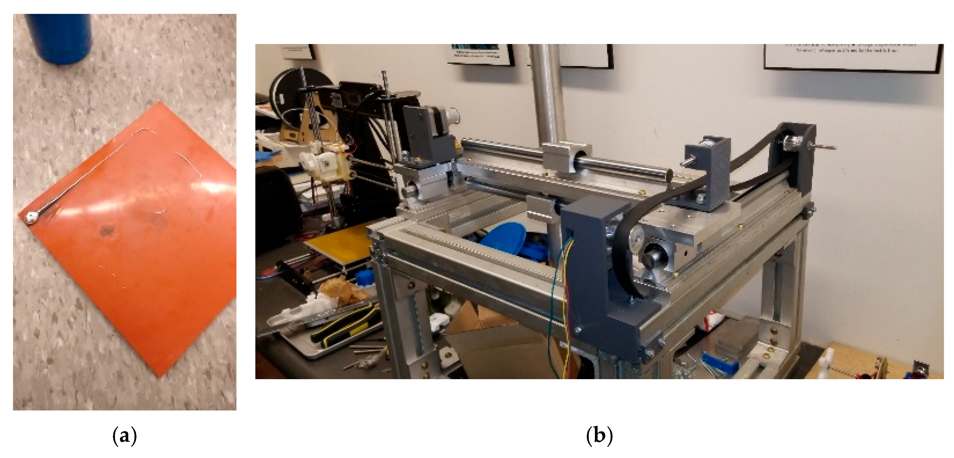
The chief problem with multi-material parts is that there are sharp material interfaces—typically an adhesive bond—between different materials which can exhibit high stress concentrations. One approach is to introduce arrays of small interlocking joints such as dovetails or similar. Further challenges for metal–ceramic and metal–plastic occur due to their different thermomechanical properties, especially differing melting points. We have been developing a method for 3D printing molten aluminium onto silicone plastic substrates to demonstrate simultaneous use of metal and plastic in a 3D printing context (
Figure 23a). This exploits the elevated degradation temperature of silicone plastic of 400–450 °C, and the reduced melting temperature of an aluminium–zinc alloy at ~400 °C.
We are currently developing an in-house custom multi-material 3D printer that will combine silicone extrusion and aluminium powder bed fusion with a milling head integrated into a single unit (
Figure 23b). Some non-3D printing processes may be integrated into 3D printing, such as subtractive machining, by integrating a two- or four-axis CNC milling tool (z degrees of freedom are provided by the work platform) for surface finishing of rough 3D printed parts. This introduces a potential problem of jigs if the part is not bonded to the work platform. Other non-3D printing processes may be more challenging to integrate but are nonetheless necessary, such as hot isostatic pressing to relieve internal stresses generated by lamination. Clearly, there are significant challenges to 3D printing multiple components comprising multiple materials—this is the holy grail of 3D printing.
Multi-material 3D printing is still immature [
31]. SLA (and its variants) involves UV curing of liquid polymer layer-by-layer into a solid within a vat of liquid polymer. Glass powder and fibreglass fabrics may be incorporated into composites through pre-mixing. It is limited to photopolymers and multi-material printing requires switching between different vats. Extrusion-based 3D printing involves mechanical ejection of paste through a nozzle, e.g., FDM extrusion of thermoplastic may be pre-embedded with additives such as glass powder or fibre for structural reinforcement or carbon for many functional materials. However, the most promising approach to multi-material 3D printing appears to be direct ink writing (DIW), based on the extrusion of liquid inks with characteristic shear-thinning, involving a decreasing viscosity with increasing shear rate. The design of inks provides high versatility such as the deposition of different ink layers, i.e., multi-material 3D printing. DIW printing requires low viscosity to prevent nozzle clogging but higher viscosity after deposition. The stability of the ejected fluid is determined by the dimensionless reciprocal of Ohnesorge’s number, 1 <
Z < 10 (ratio of viscosity to inertia and surface tension):
where
η = dynamic viscosity,
σ = surface tension,
ρ = density and
l = drop diameter. Fluid viscoelasticity is determined by shear stress given by the Herschel–Bulkley model:
where
= yield stress,
K = flow consistency index,
n = flow index and
= shear rate. Inkjet printing is a type of DIW method that ejects charged droplets of low-viscosity ink through an electric field. Binder jetting is a variation in which liquid polymer is jetted onto a substrate (adopted for our magnets). Aerosol jet direct write printing uses nitrogen gas to collimate aerosol droplets into a tight beam for a high resolution of ~10 μm. Electrohydrodynamic (EHD) inkjet printing uses a high electric field to draw a conductive ink through small conducting conical nozzles (Taylor cones) onto a conducting substrate. Electrically conductive filament comprises polymer with conductive filler such as metal or carbon particles. This provides a higher resolution than traditional inkjet printing. For 3D printing multi-material electronics, common dielectric inks with high dielectric permittivity include PMMA and PVDF, while common metal inks include those with high loading of metal (commonly copper but aluminium, cobalt and nickel are also used) nanoparticles suspended in a liquid [
32]. Stretchable 3D printable electronics involve nanoparticle inks whose thermomechanical properties must match that of the substrate. The 3D printing of flexible materials such as silicone elastomers and hydrogels is dominated by designed inks for inkjet 3D printing [
33]. UV-initiated crosslinking with methacrylate-based polymers such as MMA/PMMA can provide tailored solidification options, e.g., self-healing polymers release reagents on damage that polymerise or crosslink. Inks require additives to prevent agglomeration that can cause nozzle clogging. Hydrophobic silica nanoparticles may be incorporated into PDMS silicone inks to reduce the tendency for nozzle clogging. Once printed, the ink is sintered. Post-printing treatment includes solvent vapour polishing with acetone. Direct write 3D printing of multiple materials involves sequentially printing conductive and insulating layers from conducting and dielectric inks, e.g., capacitors. Closed loop control of direct write 3D printing enabled the manufacture of double-layer high voltage capacitors comprising PMMA films, onto which conductive inks based on silver suspension in MMA solution were applied [
34]. Direct write can 3D print a multilayer grid piezoelectric composite sandwiched between conductive electrode layers [
35]. The composite comprised a PDMS elastomer matrix with embedded piezoceramic particles of PbTiO
3 with electrodes of Ag and multi-walled carbon nanotubes. Piezoceramics offer superior performance to piezopolymers. The promise of direct writing for multi-material-integrated 3D printing is reliant on the crafting of a library of inks.
4. Conclusions
We have shown (i) a successful proof of concept of a 3D printed electric motor; (ii) that more development, however, is required for a practical 3D printed motor; and (iii) that both theory and an experiment involving conventional wire coils contrasted with LOM-derived wire coils demonstrate that the poor performance of the 3D printed motor lies in the number of coil turns. Furthermore, the 3D printed rare earth stator magnets were inferior to the conventional magnets of the commercial motor. We have demonstrated that a functional DC electric motor may be 3D printed, but there are several challenging tasks that must be solved to robustify and automate the process. This step will be crucial to render 3D printed motors practical. Furthermore, to round out the electric motor into a full motor system, we must incorporate integrated sensors, gearing and computational electronics. Although conductive and semiconductor polymers offer potential, their deployment for power distribution is debatable. Nevertheless, 3D printing all mechatronic components, including suites of sensors and active electronics, opens the possibility of 3D printing robots and other kinematic machines. If so, other kinematic machines may be 3D printed, including different types of 3D printers, milling machines, lathes, drills, etc. These are machines of production. Three-dimensional printing motor systems would constitute a universal construction capability in building generic machines of production. However, the first step is to demonstrate 3D printing of mechatronic components, including electric motors.


