Article

A Comparative Investigation of CFD Approaches for Oil–Air Two-Phase Flow in High-Speed Lubricated Rolling Bearings

1
College of Mechanical and Electrical Engineering, Nanjing University of Aeronautics and Astronautics, Nanjing 210016, China
2
Hunan Aviation Powerplant Research Institute, Aero Engine Corporation of China (AECC), Zhuzhou 412002, China
*
Author to whom correspondence should be addressed.
Machines 2025, 13(8), 678; https://doi.org/10.3390/machines13080678 (registering DOI)
Submission received: 1 July 2025 / Revised: 23 July 2025 / Accepted: 28 July 2025 / Published: 1 August 2025
(This article belongs to the Section Machine Design and Theory)

Abstract

Analyzing the two-phase flow behavior in bearing lubrication is crucial for understanding friction and wear mechanisms, optimizing lubrication design, and improving bearing operational efficiency and reliability. However, the complexity of oil–air two-phase flow in high-speed bearings poses significant research challenges. Currently, there is a lack of comparative studies employing different simulation strategies to address this issue, leaving a gap in evidence-based guidance for selecting appropriate simulation approaches in practical applications. This study begins with a comparative analysis between experimental and simulation results to validate the reliability of the adopted simulation approach. Subsequently, a comparative evaluation of different simulation methods is conducted to provide a scientific basis for relevant decision-making. Evaluated from three dimensions—adaptability to rotational speed conditions, research focuses (oil distribution and power loss), and computational economy—the findings reveal that FVM excels at medium-to-high speeds, accurately predicting continuous oil film distribution and power loss, while MPS, leveraging its meshless Lagrangian characteristics, demonstrates superior capability in describing physical phenomena under extreme conditions, albeit with higher computational costs. Economically, FVM, supported by mature software ecosystems and parallel computing optimization, is more suitable for industrial design applications, whereas MPS, being more reliant on high-performance hardware, is better suited for academic research and customized scenarios. The study further proposes that future research could adopt an FVM-MPS coupled approach to balance efficiency and precision, offering a new paradigm for multi-scale lubrication analysis in bearings.

1. Introduction

Bearings are critical components in transmission systems, often operating at ultra-high speeds (DN values up to 3 × 10 6 ). Under such conditions, intense frictional heat is generated at contact points between rolling elements, raceways, and cages. Additionally, viscous dissipation of lubricating oil adds to the heat load. If this heat is not effectively dissipated, bearing temperatures rise, leading to performance degradation and reduced service life. Efficient lubrication not only reduces friction but also aids in heat removal via circulating oil, ensuring reliable operation. However, high-speed rotation induces complex oil–air two-phase flows in the bearing cavity, involving oil-rolling element collisions and strong airflow interactions, making lubrication analysis highly challenging. Current lubrication designs rely heavily on empirical methods, which are often inefficient and costly. To improve lubrication performance and enable precision design, a deeper investigation into oil-jet lubrication in high-speed rolling bearings is essential.

1.1. Related Works

The primary approaches for investigating oil–air two-phase flow in bearing lubrication include experimental measurement, theoretical analysis, and CFD simulations.
Experimental studies play a foundational role in understanding oil–air two-phase flow in bearing lubrication. They not only provide essential data for theoretical model development and CFD validation, but also enable the discovery of novel phenomena that drive future research. Early efforts established fundamental platforms for oil film observation. For instance, Damiens et al. [1] developed an adjustable-cage-clearance ball bearing test rig to examine oil and grease lubrication under different cage clearances, revealing their distinct effects on film formation. Liang et al. [2] further advanced experimental capabilities with a high-speed disc–ball interferometric system, achieving observation speeds up to 42 m/s. Their findings showed rapid, asymmetric oil film thinning under starved lubrication at critical speeds, attributed to centrifugal effects. Building on this, a quantitative relationship between centrifugal force and oil film decay was established through detailed data analysis [3]. Recognizing the limitations of simplified disc–ball models, Liang et al. [4] developed a visualized bearing platform to more accurately replicate real-world lubrication conditions. This setup allowed macroscopic observation of oil–air distribution and explored the impact of cage geometry and surface structure on lubrication behavior. However, fine-scale film characterization remained elusive. To address this, Chen et al. [5] integrated synchronized dual-camera imaging with laser-induced fluorescence (LIF), revealing that much of the lubricant bypasses the contact zone and demonstrating oil film decay via combined experimental and numerical analysis. Complementary studies by Peterson et al. [6] introduced a setup for analyzing lubrication and friction in individual roller–cage systems, highlighting the significant influence of cage clearance on surface oil distribution. Similarly, de Cadier de Veauce et al. [7] measured power loss in bearings (types 6311 and 6208) under varying oil levels, developing a drag-loss model that correlates with lubrication conditions.
The application of thin-film interference techniques has notably enhanced the accuracy of lubricant film measurement, shifting experimental studies from qualitative visualization to quantitative characterization. From traditional disc–ball tests to advanced transparent bearing platforms, experimental advances continue to refine lubrication theory and understanding. Despite these achievements, experimental research still faces limitations—such as high costs, complexity, and difficulties in replicating extreme operational environments—that restrict its ability to fully capture high-speed, high-load lubrication behavior. Therefore, while indispensable, experimental methods must increasingly be complemented by theoretical and computational approaches to provide a comprehensive understanding of bearing lubrication under demanding conditions.
As for the theoretical analysis, building upon the experiments of Beauchamp Tower, Osborne [8] pioneered the elastohydrodynamic lubrication (EHL) theory, laying a solid theoretical foundation for lubrication and friction analysis. Tian et al. [9] developed a dynamic model based on thermal elastohydrodynamic lubrication (TEHL) theory, conducting an in-depth investigation of the sudden load reduction process in angular contact ball bearings. Their work revealed that abrupt load reduction could induce bearing skidding and emphasized the necessity of avoiding this phenomenon. Wen et al. [10] constructed a multi-degree-of-freedom EHL friction dynamics model by incorporating five degrees of freedom for the inner ring, six for the balls, and six for the cage. This model provided new insights into how varying degrees of oil starvation affect bearing lubrication performance. Zhao et al. [11] integrated newly developed fluid resistance and rolling contact traction models into bearing equilibrium equations, proposing a quasi-static fluid-structure interaction model to describe complex friction behaviors involving both rolling and sliding under solid lubricant conditions. Based on this model, they conducted a thorough analysis of bearing power loss components, offering new theoretical guidance for bearing design. The current theoretical framework for bearing lubrication remains centered on EHL principles.
Through coupling with thermal analysis, multi-body dynamics, and other factors, researchers have developed more accurate and practical EHL-based bearing lubrication models. However, this theoretical system primarily focuses on quantitative analysis of contact lubrication performance and performance evaluation under presumed lubrication states, while still lacking in characterizing the two-phase flow mechanisms and spatiotemporal oil–air distribution inside bearings.
Computational fluid dynamics (CFD) has emerged as a powerful tool for investigating oil–air two-phase flow in high-speed bearing lubrication. Compared to experimental methods, CFD offers significant advantages in visualizing and analyzing the spatiotemporal distribution of lubricants within the bearing cavity, especially under extreme operating conditions. It provides multi-dimensional insights into flow fields at relatively low cost, making it a valuable approach for exploring lubrication performance in depth.
Wu et al. [12] established an oil-jet lubrication model for rolling bearings using the Finite Volume Method (FVM), analyzing the inhomogeneity of oil distribution and heat transfer in jet-lubricated bearings. Building on this work, they further investigated the effects of nozzle quantity and oil flow rate on bearing lubrication performance. Several scholars have employed CFD methods to achieve precise descriptions of bearing lubrication physics and evaluate lubrication performance [13]. Yan et al. [14] integrated a six-degree-of-freedom (DOF) ball, five-DOF inner ring, and three-DOF cage dynamic model with CFD simulations, developing a more realistic fluid-thermal coupled bearing model. This enabled analysis of cage structure effects on heat dissipation under ultra-high-speed conditions. Deng et al. [15] established a nonlinear bearing dynamics model based on EHL theory to predict bearing motion and power loss, which served as boundary conditions for their CFD model, creating a more accurate lubrication simulation. Liu et al. [16] developed a dynamic model of relative motion between balls and cage, incorporating cage clearance effects into bearing CFD analysis to study its impact on lubrication performance. Gao et al. [17] conducted CFD simulations of flow resistance loss between plates with cylindrical rollers, examining how geometric parameters, operating conditions, and fluid properties affect resistance loss. They subsequently built a complete cylindrical roller bearing CFD model to predict churning power loss, validating results against traditional empirical models [18]. Hu et al. [19] created a CFD model for ball bearing lubrication, developing a churning loss prediction model through orthogonal experimental design, dimensional analysis, and multiple linear regression, with experimental verification. Wei et al. [20] employed the Moving Particle Semi-implicit (MPS) method to model oil-jet-lubricated ball bearings, predicting churning loss and validating accuracy experimentally. They extended this work to simulate oil distribution in oil-bath-lubricated bearings, confirming results through visualization experiments [21].
In fluid mechanics, both Eulerian and Lagrangian frameworks are employed to describe fluid motion. In CFD, these correspond to Eulerian-based methods such as FVM, and Lagrangian-based methods such as MPS. The FVM has become the dominant and mature technique for bearing lubrication analysis, especially when coupled with multi-body dynamics models to enable detailed predictions of lubricant behavior and power loss. In contrast, the MPS method remains relatively novel in this field but shows considerable potential due to its natural ability to handle free surfaces and complex interface dynamics in two-phase flows.

1.2. Motivation and Contribution

These studies have successfully employed various methodologies to establish effective models for characterizing bearing lubrication performance. However, there remains a lack of systematic guidance for selecting appropriate simulation approaches across different bearing lubrication scenarios. This study therefore aims to develop a decision-making framework for CFD simulation strategies in bearing lubrication analysis, providing comparative criteria for method selection. Using identical bearing models as the research object, both FVM and MPS numerical models were constructed. Through comparative computational analysis, this work establishes reference benchmarks to inform CFD simulation strategy decisions for bearing lubrication performance evaluation. The contributions of this work lie in two aspects: (1) Development of numerical computation models for bearing lubrication performance based on both FVM and MPS methods; (2) Establishment of a reference framework to guide CFD simulation strategy selection in bearing lubrication studies, offering novel perspectives for future research in this field.

1.3. Organization

The remaining of this paper is arranged as follow. Section 2 details the bearing parameters and boundary conditions implemented in the developed models. Section 3 and Section 4 present the bearing numerical models constructed using FVM and MPS methods, respectively, along with corresponding results analysis. Section 5 provides a comparative discussion of both modeling approaches. Finally, Section 6 summarizes the key findings as conclusions.

2. Problem Formulation and Preliminary Experiments

2.1. Oil Injection Mechanism of Bearing

Rolling bearings are precision transmission components that convert sliding friction between rotating shafts and bearing housings into rolling friction, thereby reducing frictional losses. A typical bearing consists of four main parts: inner ring, outer ring, rolling elements (balls), and cage. As shown in Figure 1, this study focuses on a customized ball bearing specifically designed for a particular transmission system, capable of reaching maximum rotational speeds up to 20,900 rpm, with detailed dimensional parameters provided in Table 1. Given the high-speed operational characteristics of this bearing, the research employs an oil-jet lubrication mechanism where lubricant is directly injected onto the ball surfaces through small-diameter nozzles, as illustrated in Figure 1. The selected lubricant is 4450 aviation gear oil, with its physical properties detailed in Table 2.
During actual operation, the bearing’s inner ring is tightly fitted onto the rotating shaft while the outer ring remains stationary within the bearing housing. As the shaft rotates relative to the housing, the balls and cage between the inner and outer rings undergo complex relative motions to achieve rolling friction and support shaft rotation. When the bearing operates, its outer ring remains fixed while the inner ring rotates counterclockwise at speed n. Under ideal conditions where perfect rolling contact is assumed between the balls and raceways (with no slipping), the balls and cage revolve around the inner ring’s axis at the same orbital speed n m , maintaining the same rotational direction as the inner ring. In addition to this orbital motion, each bearing ball simultaneously spins about its own centroidal axis (parallel to the inner ring’s rotation axis) in the opposite direction at a rotational speed n R .
n m = 1 2 n i 1 D b a l l d m
n R = d m 2 D b a l l n i 1 D b a l l 2 d m 2
where n i represents the rotational speed of inner ring, D denotes the ball diameter, and d m signifies bearing pitch diameter.
The FVM and MPS modeling of two-phase flow in ball bearings presented in this paper were developed based on the following fundamental assumptions:
  • Incompressible viscous lubricant: Incompressible viscous fluid: The lubricating oil is treated as an incompressible Newtonian fluid, meaning its density remains constant while accounting for viscous effects.
  • Isothermal flow condition: The system maintains constant temperature, resulting in temperature-independent lubricant viscosity.

2.2. Experimental System

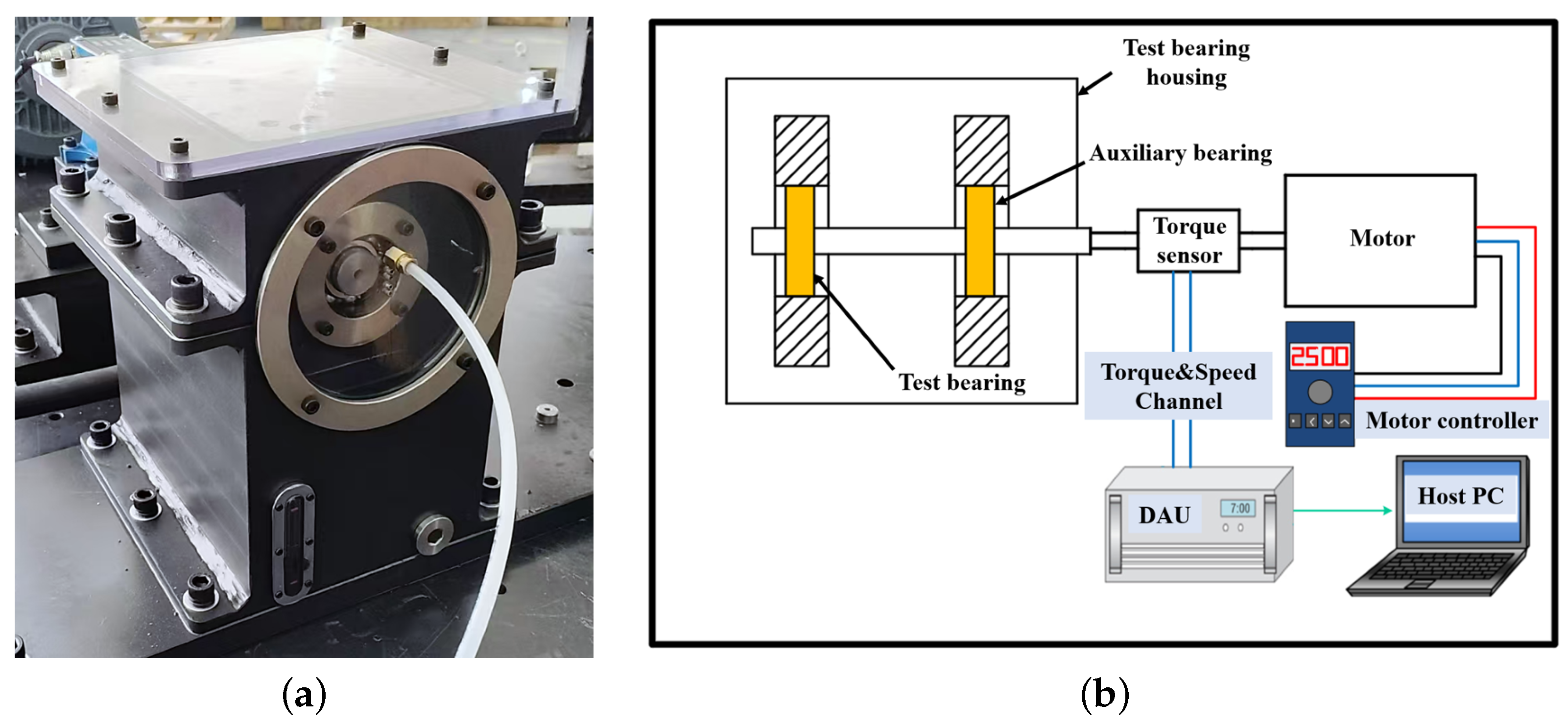
To verify the accuracy of the proposed model in characterizing the two-phase flow in bearings, we developed a custom-designed adjustable test platform for analyzing bearing churning losses, as shown in Figure 2. The test platform primarily consists of the following components: an electric motor, a test bearing housing, a torque sensor, couplings, and a control system.
The torque sensor used to measure power loss is installed between the electric motor and the test bearing housing. During testing, the bearings operate at specified speeds, with the test bearings lubricated by jet lubrication and the auxiliary bearings lubricated by grease. Since no external load is applied to the bearing housing, the input shaft only experiences drag torque, enabling precise evaluation of the churning losses in the test bearings.
Figure 2 shows the test drivetrain mounted on the adjustable attitude platform of the custom-designed test setup, which consists of an electric motor, a bearing housing for testing, a torque sensor, and couplings. The experiments employed a Lanmec, Nantong 226000, China ZJ-50A torque speed sensor with a measuring range of ±50 N·m torque and maximum rotational speed capability of 6000 RPM, featuring a high accuracy class of ±0.2% of full scale. This torque sensor is positioned between the input shaft of the test bearing housing and the output shaft of the motor. It is connected to both shafts via diaphragm couplings, serving as an integral part of the drivetrain to transmit the motor’s speed and torque to the test bearing housing.
Based on the findings of Chen et al. [22], we can reasonably propose the following hypothesis: under extremely low-load conditions, bearing friction losses and drivetrain losses remain nearly constant regardless of variations in lubricant quantity. Therefore, before conducting the formal test series, we first performed a set of calibration experiments under oil-free conditions to determine the baseline drag torque T 0 , which represents the combined influence of drivetrain losses and bearing friction losses at different rotational speeds. Subsequently, formal tests were conducted under specified oil-immersion conditions to measure the total drag torque T 1 , which includes drivetrain losses, bearing friction losses, and churning losses. Based on these measurements, the drag torque attributable solely to churning losses can be calculated as:
T = T 1 T 0
To validate whether the FVM and MPS two-phase flow modeling approaches can accurately describe the two-phase flow behavior in ball bearings, this study employed SKF, SE-415 50 Gothenburg, Sweden 6206 bearings—geometrically similar to the custom-designed bearings—for establishing the FVM and MPS models, followed by comparative verification against experimental measurements, given the practical challenges in creating customized bearing test conditions. It should be emphasized that all modeling and analysis work on the custom bearings using both FVM and MPS methods were conducted only after the churning loss validation with SKF 6206 bearings, with the sole purpose of further comparing the differences between FVM and MPS methods in bearing two-phase flow analysis.
Both the test bearing and the auxiliary bearing were SKF 6206, with some key bearing parameters listed in Table 3. Based on the geometric model of the 6206 bearing provided by SKF, further preprocessing was performed to generate a mesh, forming an FVM model corresponding to the test bearing. The test bearing was lubricated by oil jet lubrication, with specific lubrication parameters detailed in Table 4.

2.3. Preliminary Results

To obtain reliable data for each test point, three sets of repeated measurements were conducted. Data acquisition was performed for 20 s after the torque stabilized, using a 100 Hz sampling rate to acquire 2000 raw data points per set. The acquired raw data underwent low-pass filtering to remove high-frequency noise, rigorous outlier removal, and finally, the mean was calculated. The calculated mean was then subtracted by the zero-point offset of the torque sensor under static conditions, thereby determining the final measurement result for that test point.
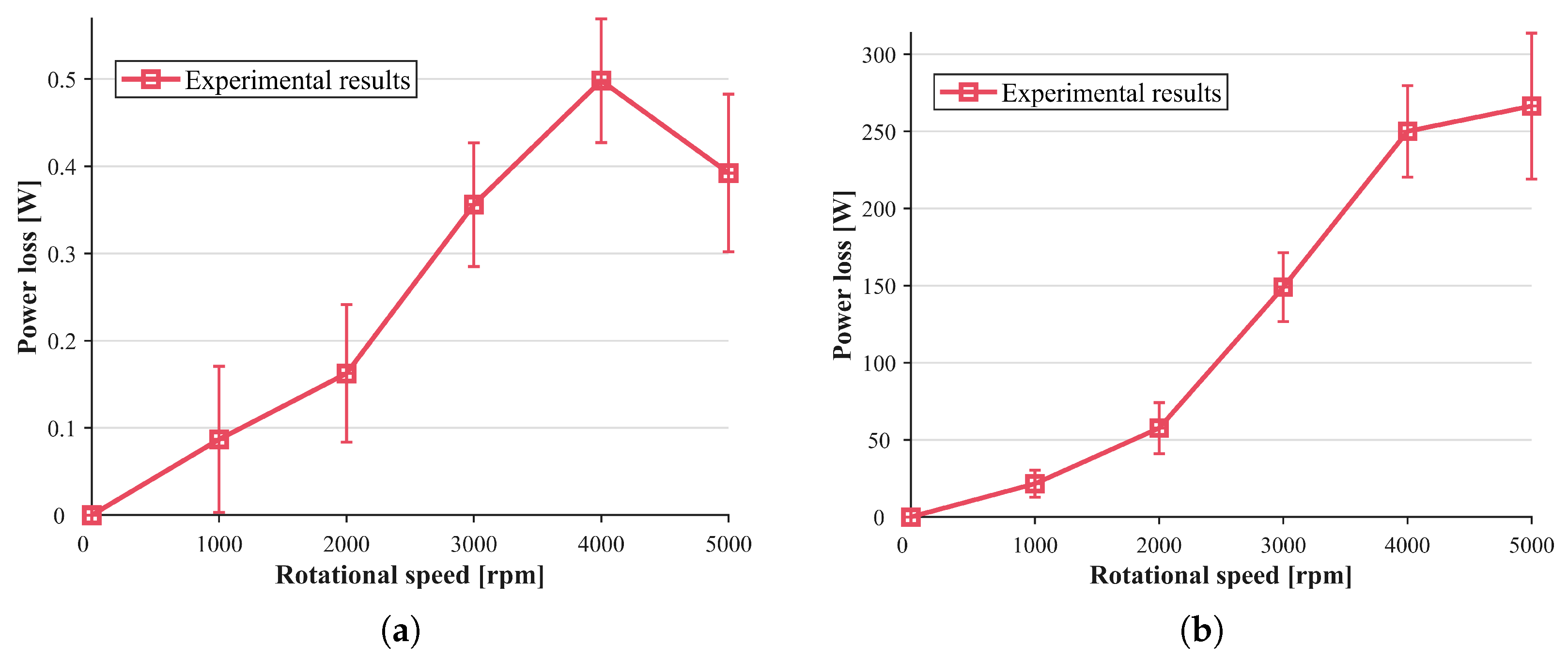
Figure 3 displays the derived churning torque trend, which was calculated by deducting the baseline drag torque from the measured total resistance torque across various operating speeds of the test bearing. The error bars on experimental data points represent the standard deviation among the mean values obtained from three independent measurement sets under each operating condition. The measured churning torque of the test bearing exhibits a consistent increase with rotational speed within the 0–4000 rpm range. However, an anomalous reduction in churning torque is observed at 5000 rpm. This phenomenon may be attributed to a transition in lubricant flow regime from predominantly laminar to turbulent flow, coupled with reduced oil volume fraction inside the bearing due to centrifugal effects. These combined factors lead to decreased effective viscosity of the oil–air mixture, consequently resulting in the observed torque reduction.
In their work proposing a computational model for churning loss in high-speed rolling bearings based on numerical calculations, Gao et al. [18] investigated the relationship between rolling element drag and Reynolds number. Their findings revealed that as the Reynolds number increases, the drag coefficient of rolling elements continuously decreases and eventually stabilizes in the high Reynolds number region. During continuous increases in bearing speed, the Reynolds number in the flow field between bearing raceways progressively rises. In this process, the influence of rotational speed on churning torque becomes insufficient to counteract the effect of Reynolds number reduction, consequently leading to a decrease in churning torque. The study by Gao et al. [23] on the mechanism of centrifugal force in lubricant loss of ball bearings provides evidence for the abnormal reduction in churning torque. Their research reveals that under high-speed conditions, the lubricant on the inner ring wall of rolling bearings migrates toward both sides of the raceway under centrifugal force. Given that the surface tension-induced backfilling effect is significantly weaker than the centrifugal force and thus negligible, this phenomenon reduces the volume fraction of lubricant between bearing raceways.
The torque-speed data measured directly in the experiment only reflect the resistance characteristics at specific rotational speeds, which is insufficient to fully characterize the power loss. Therefore, to accurately evaluate churning loss, it is necessary to calculate the churning loss based on the churning resistance torque using the following formula:
P c h = 1000 T n 9550
where P c h is power loss [W], T is resistance torque [Nm], and n is rotational speed [rpm].
Figure 3 illustrates the variation trend of churning power loss in the test bearing with rotational speed. The experimental results demonstrate that the bearing’s churning power loss progressively increases with rising rotational speed. Notably, although an anomalous decrease in churning torque was observed at 5000 rpm, this reduction’s effect on power loss was counterbalanced by the increased rotational speed. Consequently, the test bearing exhibits a strictly monotonic increasing trend in churning power loss throughout the entire speed range from 0 to 5000 rpm.

3. FVM Model

3.1. Numerical Method

3.1.1. Governing Equations

All fluid flow problems must satisfy the law of mass conservation, which can be conceptually described as: the net mass flow rate of fluid exiting a control volume through its surfaces equals the time rate of decrease in fluid mass within the control volume. When this control volume becomes infinitesimally small yet still contains sufficient fluid molecules to be treated as a continuum, it can be termed a fluid element. Considering a spatially fixed infinitesimal fluid element as the research object, the Eulerian form of the continuity equation can be expressed as:
ρ t + ( ρ u ) x + ( ρ v ) y + ( ρ w ) z = 0
Rewritten in its general form containing the velocity gradient tensor:
ρ t + · ( ρ V ) = 0
where ρ t represents the time rate of mass decrease within the fluid element, · ( ρ V ) denotes the net mass flow rate out of the fluid element.
The law of momentum conservation is another fundamental principle that all fluid flow systems must satisfy. This law can be conceptually described as the time rate of change of momentum within a fluid element equals the sum of all body and surface forces acting upon that fluid element, essentially representing Newton’s second law of motion. Considering a spatially fixed infinitesimal fluid element as the research object, the conservation-form Navier–Stokes (N–S) equations can be expressed as:
( ρ u ) t + · ( ρ u V ) = P x + τ x x x + τ y x y + τ z x z + ρ f x
( ρ v ) t + · ( ρ v V ) = P y + τ x y x + τ y y y + τ z y z + ρ f y
( ρ w ) t + · ( ρ w V ) = P z + τ x z x + τ y z y + τ z z z + ρ f z
where the left-hand side of each equation represents the time rate of momentum change within the fluid element, τ x x , τ y x , τ z x , τ x y , τ y y , τ z y , τ x z , τ y z , τ z z denote viscous shear stress components arising from fluid viscosity, P indicates the pressure acting on the fluid element, f x , f y , f z represent the body forces per unit mass acting on the fluid element.

3.1.2. Turbulence Model

The fundamental governing equations mentioned above are coupled nonlinear partial differential equations, making direct solution of the N–S equations extremely challenging, as no closed-form general solution currently exists. To reduce computational complexity, we introduce the k- ε turbulence model based on these governing equations. This approach employs statistical principles to describe turbulence as a stochastic process, achieving equation closure by incorporating turbulent kinetic energy (k) and turbulent dissipation rate ( ε ), thereby enabling turbulence prediction through its statistical characteristics.
In high-speed bearing lubrication flow fields, intense swirling flows, secondary flows, and even flow separation phenomena induced by rotating components are prevalent. Accurately capturing these complex flow structures is crucial for understanding lubricant distribution and power loss. To this end, the RNG k- ε turbulence model was selected for this study. Compared to other models, it demonstrates superior performance in predicting swirling flows, as its RNG theory inherently accounts for swirling effects. This enables more accurate simulation of the complex vortices generated by ball spinning and orbital motion within high-speed bearing cavities. The model has been successfully applied to similar studies of internal flows in rotating machinery and oil–air two-phase flow simulations.
The RNG k- ε model is a widely used two-equation turbulence model, consisting primarily of the turbulent kinetic energy (k) equation and dissipation rate ( ε ) equation:
( ρ k ) t + · ( ρ k V ) = x i μ + μ t σ k k x i + G k ρ ε
( ρ ε ) t + · ( ρ ε V ) = x i μ + μ t σ ε ε x i + 1 k C 1 ε η ( 1 η / η 0 ) 1 + β η 3 G k C 2 ε ρ ε 2 k
μ t = ρ C μ k 2 ε
η = ( 2 E i j · E i j ) 1 / 2 k ε
E i j = 1 2 u i x j + u j x i
where k represent turbulent kinetic energy, ε represent dissipation rate, G k represent turbulence kinetic energy generation due to mean velocity gradients, μ t represent turbulent viscosity and model constants C 1 ε = 1.42 , C 2 ε = 1.68 , C μ = 0.0845 , η 0 = 4.377 , β = 0.012 .
The two transport equations of the RNG k- ε model share the same form as the N–S equations. The left-hand side represents the time rate of change of turbulent kinetic energy and dissipation rate within the fluid element.

3.1.3. Multiphase Flow Model

The oil-jet lubrication flow field in rolling bearings contains two immiscible fluid phases—lubricating oil and air. To characterize the morphology and spatial distribution of the oil phase within this flow field, a multiphase flow model must be employed to dynamically track the interfacial behavior between these phases.The Volume of Fluid (VOF) method is an Eulerian–Eulerian multiphase modeling approach that treats different fluid phases as continuous media. Since the phases remain distinct without intermixing, the model introduces the concept of phase volume fraction α i . This scalar quantity α i , defined as a continuous function of both space and time, represents the volumetric proportion of the i-th phase within a given control volume.
The phase volume fraction α i has the following physical significance:
  • When α i = 1 : The control volume is entirely filled with the i-th phase fluid.
  • When α i = 0 : The i-th phase fluid is completely absent from the control volume.
  • When α i = k ( 0 < k < 1 ) : The control volume contains a mixture of the i-th phase with other phases.
The volume fractions of all phases must satisfy the conservation relation:
i = 1 n α i = 1
Since multiple phases with different densities ρ i and viscosities μ i may coexist within a single control volume, the mixture properties cannot be represented by any single phase’s parameters. The VOF model therefore calculates effective properties through volume-weighted averaging.
ρ = i = 1 n α i ρ i
μ = i = 1 n α i μ i

3.2. Meshing and Boundary Conditions

During the operation of ball bearings, a series of complex relative motions occur among the inner ring, outer ring, cage, and rolling elements. This study focuses specifically on scenarios where the outer ring remains stationary. In such cases, the bearing’s outer ring can be regarded as the stationary component of rotating machinery, forming a static system. Conversely, the inner ring, cage, and rolling elements constitute the dynamic rotating portion of the machinery. The interaction between these static and rotating systems gives rise to typical rotor–stator interaction (RSI) phenomena. RSI phenomena can be simulated using various mesh control strategies, including dynamic mesh (DM) and sliding mesh method (SMM). However, due to the bearing’s inherent structure—where only extremely thin lubricating films exist between rolling elements and the cage/ring—employing dynamic mesh methods for bearing lubrication flow field simulations would incur prohibitively high computational costs and frequently lead to numerical divergence. Therefore, this research adopts SMM to simulate wall motions within the bearing.
The SMM is a transient computational mesh control approach that divides the entire computational domain into subdomains with distinct motion states, establishing interfaces between them for data exchange. During computation, adjacent subdomains slide along these interfaces according to predefined motions while simultaneously exchanging flow parameters across the interfaces.
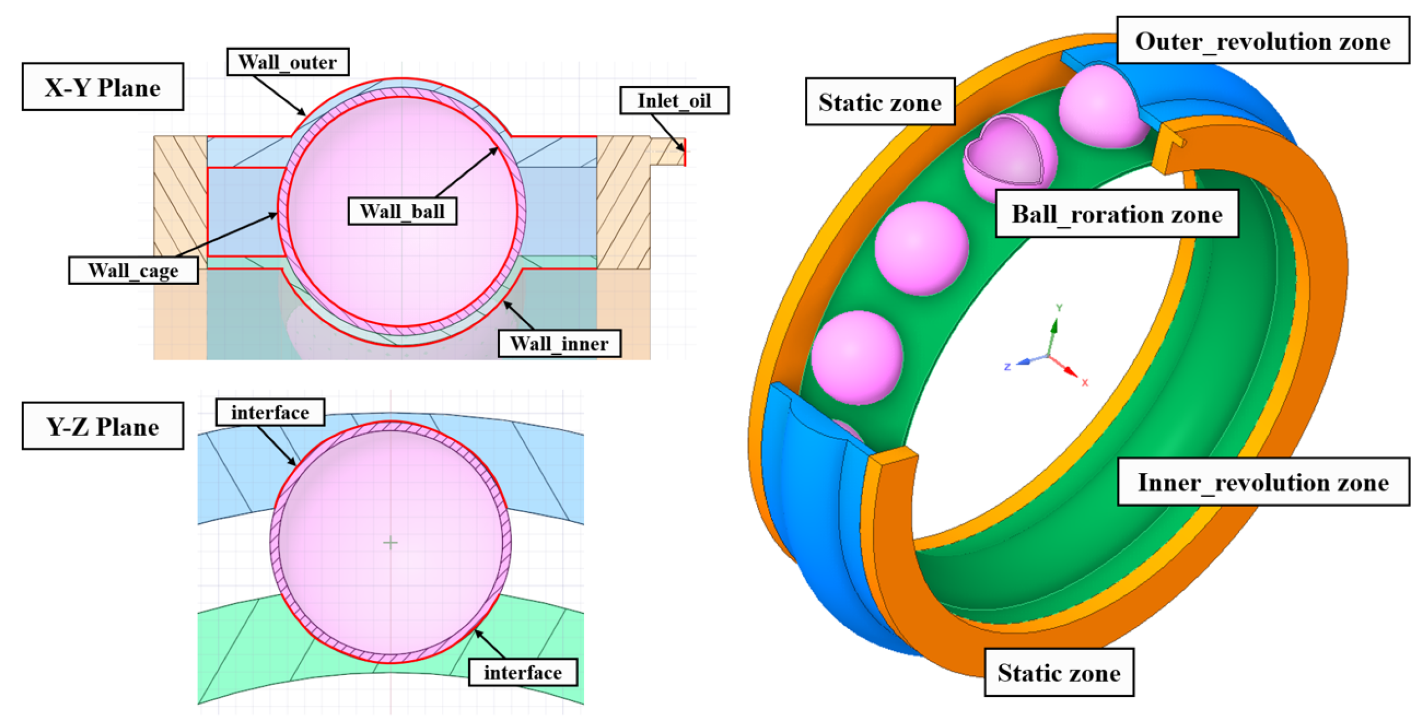
Based on the relative kinematic relationships of bearing components, the lubrication fluid domain is divided into five computational subdomains as shown in Figure 4. The front and rear portions constitute stationary side domains, while the interior is partitioned by the cage into inner ring rotating domain and outer ring rotating domain. The spherical shell region adjacent to each ball is defined as the ball rotating domain.
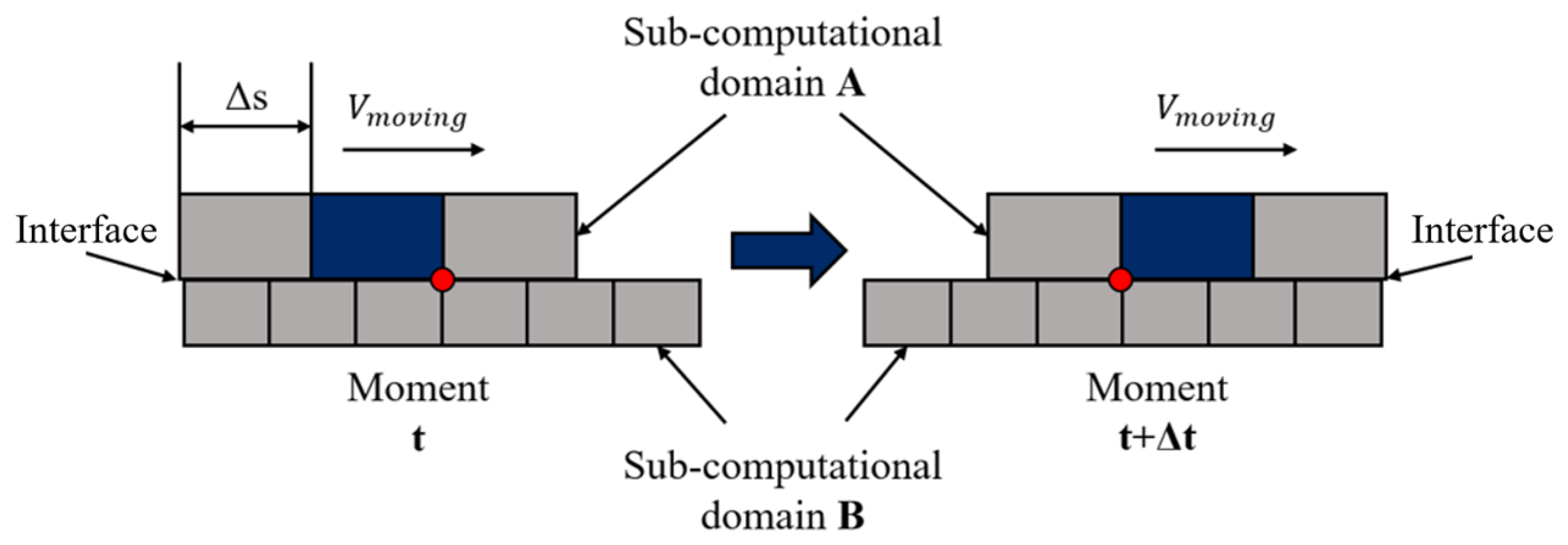
When applying the Sliding Mesh Method (SMM) for numerical simulation, relative sliding occurs between subdomains, generating new interfaces in the overlapping regions. This process repeats at each computational timestep, necessitating strict constraints on the CFD timestep size. The timestep determination is jointly governed by two key factors: the characteristic cell size near the interface and the relative sliding velocity between adjacent subdomains. Specifically, the timestep constraint can be mathematically expressed as requiring that the computational timestep must not exceed the time Δ   t for one cell from subdomain A to traverse past one grid node of subdomain B at their shared interface, as illustrated in Figure 5. This criterion ensures proper resolution of the transient interface dynamics while maintaining numerical stability throughout the sliding mesh simulation.
Δ   t Δ s V m o v i n g
where Δ   s represents the characteristic length of adjacent nodes on the interface mesh and V m o v i n g denotes the relative sliding velocity between adjacent computational domains.
Referring to the working conditions of the bearing in the actual transmission system, the outer side of the side stationary domain is set as a pressure outlet with a pressure equal to standard atmospheric pressure. The nozzle is set as the only velocity inlet in the entire computational domain, with a nozzle diameter of 1.5 mm. The inlet fluid medium is a single-phase lubricant, and the inlet flow rate of the lubricant is 1.76 L/min.

3.3. Result of FVM

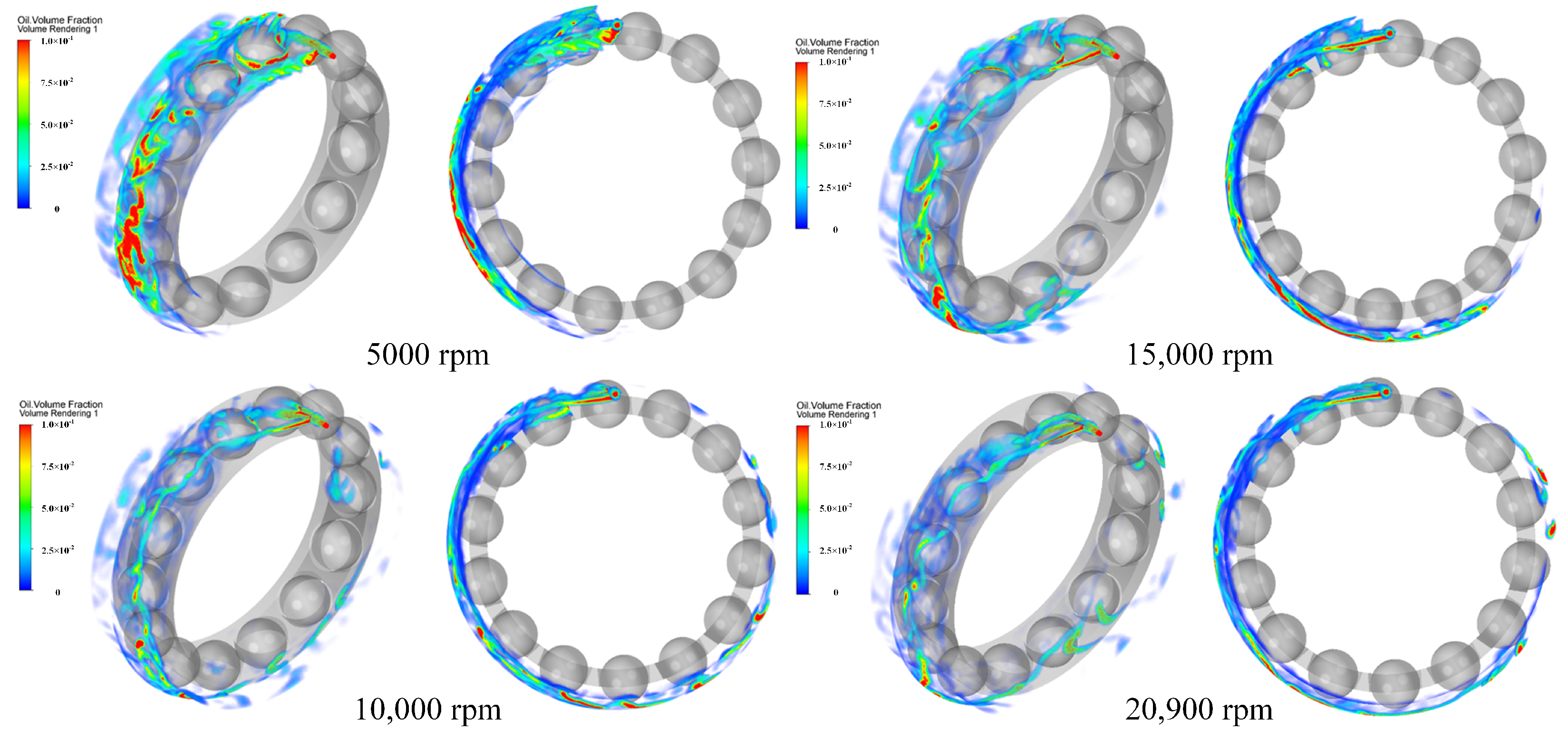
Figure 6 presents the oil–air two-phase distribution inside the single-nozzle jet-lubricated bearing simulated using FVM under different rotational speeds. The simulation results reveal significant non-uniformity in the oil–air distribution near the bearing rings: the outer ring surface exhibits a higher oil-phase volume fraction, while the inner ring surface shows a lower oil-phase concentration. This phenomenon primarily results from centrifugal forces generated by high-speed rotation, which drive lubricant migration and accumulation toward the outer ring. Furthermore, the circumferential oil distribution demonstrates notable non-uniform characteristics. The maximum oil concentration occurs near the nozzle region, with gradual attenuation along the rotational direction, eventually forming an oil-starved zone. This uneven oil distribution may adversely affect the bearing’s lubrication performance and heat dissipation capability.
Further analysis of the simulation data reveals the circumferential distribution characteristics of the oil–air two-phase flow inside the single-nozzle jet-lubricated bearing under varying rotational speeds, as illustrated in Figure 7. The results demonstrate that the overall oil volume fraction between the inner and outer rings generally decreases with increasing rotational speed. However, a noteworthy countertrend emerges: In the speed range of 5000–10,000 RPM, the lubricant volume fraction in the 270°–315° circumferential region of the bearing approaches 1 × 10 6 , indicating an almost complete absence of lubricant in this area. However, at higher speeds of 15,000–20,000 RPM, the lubricant volume fraction in this region shows a significant increase compared to lower speed ranges. When using 1 × 10 4 as the threshold for oil starvation, the proportion of starved areas exhibits the following speed-dependent variation: approximately 50% at 5000 RPM, decreasing to 37.5% at 10,000 RPM, and further dropping to about 15.3% at both 15,000 and 20,000 RPM. This demonstrates that the angular proportion of starved regions initially increases with rotational speed before stabilizing at higher speeds. The simulations also reveal that at 5000 RPM, visible lubricant distribution persists between the inner raceway and rolling elements. However, when speed reaches 10,000 RPM or higher, the lubricant volume fraction in this area decreases dramatically, transitioning into an oil-starved state.
These phenomenon suggests that elevated rotational speeds intensify flow turbulence, leading to more vigorous oil film fragmentation and enhanced aerodynamic effects on lubricant transport.
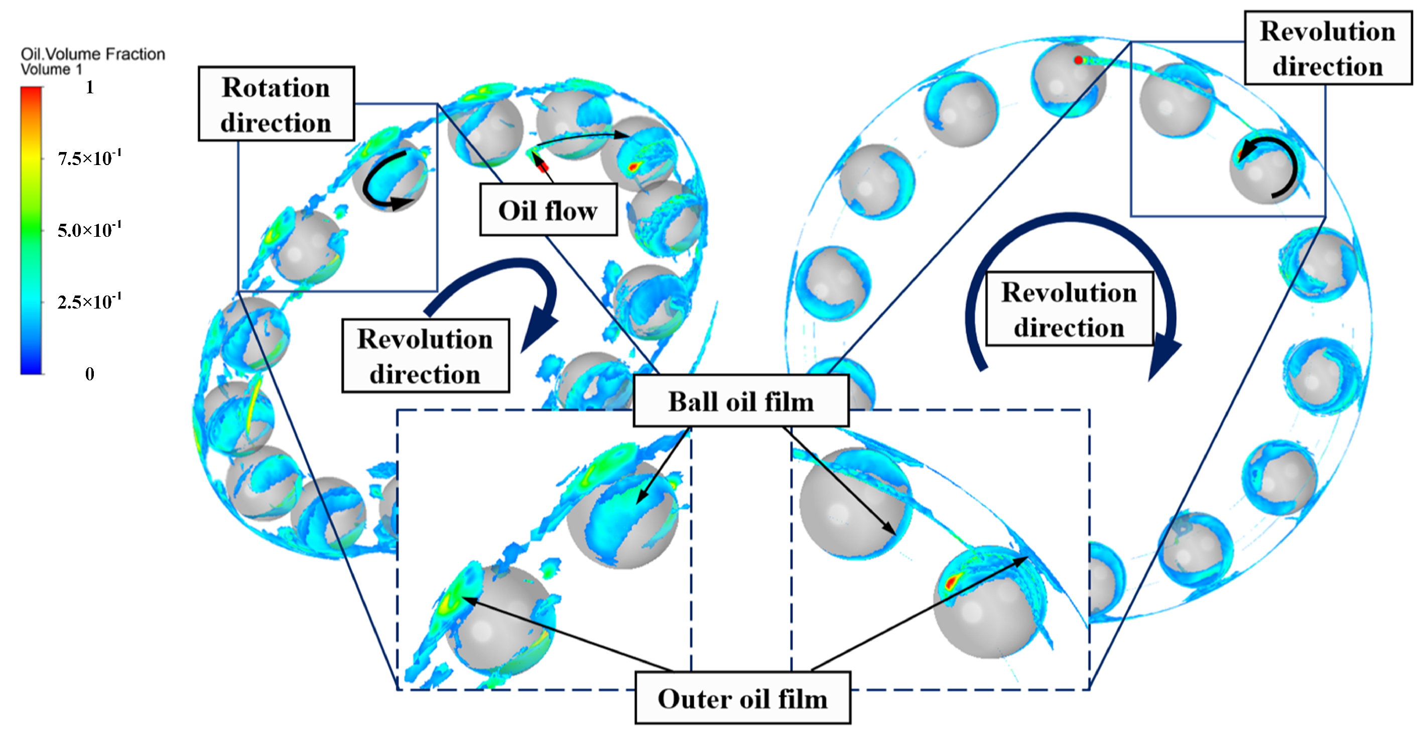
To thoroughly investigate the lubrication characteristics of bearings operating at 20,000 rpm, we selected this high-speed condition as our analysis target. Through progressive mesh refinement to accurately resolve ball motion dynamics and detailed post-processing, we successfully obtained the volumetric distribution of lubricating oil within the bearing assembly, as illustrated in Figure 8. The incorporation of ball spin effects resulted in significantly enhanced flow field uniformity, likely attributable to increased turbulent mixing induced by rotational motion. Furthermore, while maintaining consistency with prior findings in radial oil distribution patterns, our simulations revealed distinct oil film formation along the spin direction on ball surfaces, along with improved resolution of outer ring oil films. This study conclusively demonstrates the effectiveness of FVM for bearing lubrication analysis, showcasing its capability to perform multi-scale simulations tailored to specific research objectives through controlled mesh scaling. The methodology establishes a powerful tool for the design and optimization of bearing lubrication systems, particularly for extreme operating conditions.

4. MPS Model

4.1. Numerical Method

4.1.1. Governing Equations

Similarly to the FVM approach, the MPS method must also adhere to the continuity equation and momentum conservation equation. However, unlike the FVM method which focuses on fixed control volumes in space, the MPS method tracks moving fluid particles in space to establish its mathematical model. Under the assumption of incompressible flow, its Lagrangian-form continuity equation and momentum conservation equation can be expressed as follows.
D ρ D t = 0
D u D t = 1 ρ p + μ 2 u + 1 ρ f
where D D t denotes the material derivative, ρ represents fluid density, u is the particle velocity vector, p represents pressure, μ is the kinematic viscosity, f encompasses body forces.

4.1.2. Kernel Function and Particle Density

The MPS method employs physically representative particles to replace the grid discretization used in FVM, with these particles’ physical attributes characterizing the lubricant’s properties. Interactions between fluid particles are governed by distance-weighted kernel functions, which calculate interparticle forces. The specific form of this kernel function is defined as follows.
ω i j = r e r i j 1 0 r i j < r e 0 r e < r i j
ω i j represents the interaction between neighboring particles i and j, r e is the threshold radius within which neighboring particles interact, approximately 3 to 4 times the initial particle spacing, r i j is the distance between neighboring particles i and j, as illustrated in Figure 9.
This formulation can be described textually as follows: when the distance between two adjacent particles i and j exceeds the specified effective radius r e , particles i and j are considered to have no interaction. Conversely, when the distance between them is smaller than r e , an interaction exists whose weighting factor is calculated through the defined kernel function. Extending this principle to more generalized scenarios where numerous particles exist in space, with every particle pair’s interaction governed by the kernel function, the MPS method introduces a particle density model to maintain fluid incompressibility by limiting the maximum number of particles within any given particle’s effective radius. This constraint is mathematically expressed as follows.
n i = j i ω r i j
where n i is particle density of particle i.

4.1.3. Particle Action Model

In the MPS method, the interactions between particles are categorized into two main types: one is the interaction force between particles, and the other is the fluid’s viscosity and pressure. To describe the first type of interaction between particles, the MPS method introduces a gradient operator model, which is mathematically expressed as follows.
φ i = d n 0 j i φ j φ i r j r i 2 r j r i ω i j r j r i
where φ represents the scalar physical parameter of a particle, r i and r j are the spatial position vectors of particles i and j, respectively, and n 0 is the initial particle density.
To describe the second type of particle interaction, the MPS method introduces a Laplacian operator model as follows.
2 φ i = 2 d λ n 0 j i ( φ j φ i ) ω i j ( | r j r i | )
λ = j i ω i j r i j 2 j i ω i j

4.2. Result of MPS

Figure 10 illustrates the oil distribution inside a single-nozzle jet-lubricated bearing under different rotational speeds simulated using the MPS method. The results reveal significant non-uniformity in the oil–air distribution near the inner and outer rings, consistent with FVM simulations, showing higher oil-phase volume fractions on the outer ring surface and lower fractions on the inner ring surface. The circumferential oil distribution also exhibits notable non-uniformity, with the highest oil concentration near the nozzle, gradually decreasing along the rotational direction and forming oil-starved zones in certain areas, aligning with FVM results. Notably, a small oil accumulation zone appears at a specific angle range opposite to the bearing’s rotation direction, attributed to oil particle collisions with rolling elements causing localized adhesion. This phenomenon slightly differs from FVM simulations, where such accumulation was less pronounced.
Through further analysis of the simulation data, we have summarized the changing trends of the circumferential distribution of oil–gas two-phase flow inside a single-nozzle injection lubricated bearing under different rotational speeds, as shown in Figure 10. The analysis reveals that the increase in bearing speed leads to an overall decrease in the oil volume fraction between the inner and outer rings of the bearing. Notably, the range of the oil-deficient region gradually decreases with increasing rotational speed, and the circumferential distribution of the oil volume fraction tends to develop towards a more uniform distribution. These trends are consistent with the results of FVM simulations.
Further analysis of the MPS simulation results reveals that the distribution of oil particles clearly demonstrates the behavior of the free liquid surface with higher resolution. Under low-speed conditions, the oil exhibits distinct droplet formations due to surface tension, with a sharp boundary between oil and air. Notably, at 5000 rpm, evident oil dripping is observed on the cage surface and beneath the bearing. However, as the rotational speed increases, the flow becomes more turbulent, the effect of surface tension gradually diminishes, and droplet formations disappear, giving way to an oil–air mixture. For instance, while prominent oil dripping occurs beneath the bearing at 10,000 rpm, this phenomenon progressively decreases as the speed rises.

5. Experimental Verification of FVM Model and MPS Model

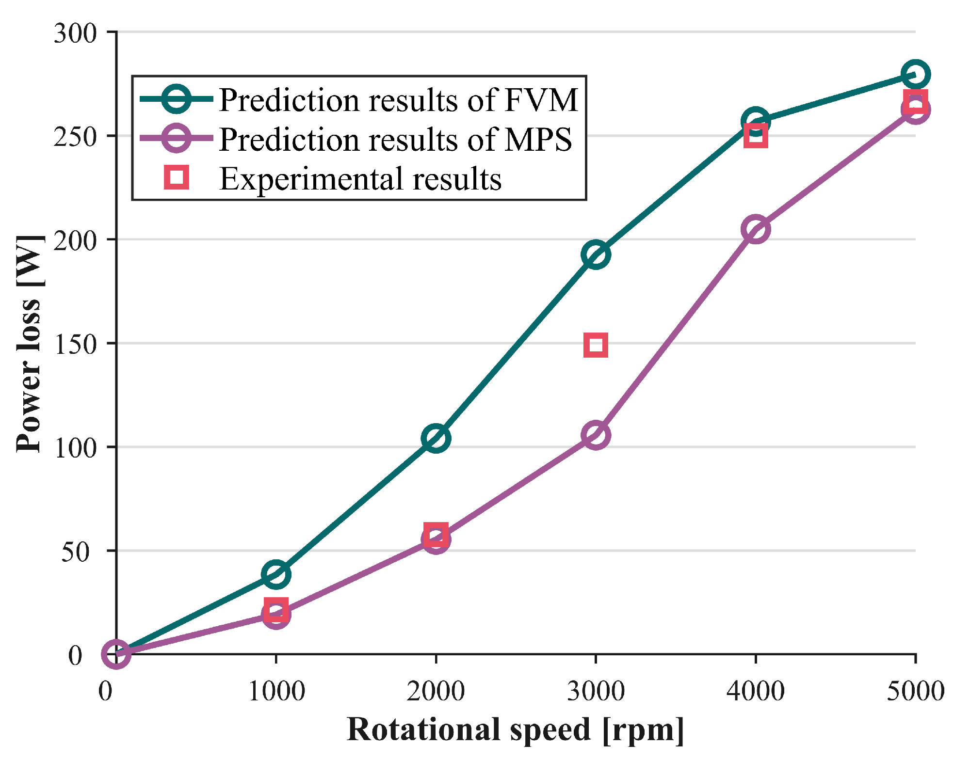
Based on the aforementioned modeling and experimental analysis of bearing SKF 6206, Figure 11 presents a comparison between the experimentally measured churning losses and the predicted values from both FVM and MPS models under specified oil-jet lubrication conditions. Notably, the simulation results of the churning power loss model showed good agreement with the experimental data. However, certain discrepancies between the simulated and experimental data were observed across different speed ranges. The comparative results reveal distinct performance characteristics between the two simulation methods: For the FVM model, the predicted churning losses show good agreement with experimental data at higher rotational speeds (4000–5000 rpm), but exhibit significant deviations in the low-speed range (1000–3000 rpm). Conversely, the MPS model demonstrates better prediction accuracy at lower speeds (1000–2000 rpm), while showing larger discrepancies with experimental values at medium speeds (3000–4000 rpm). Notably, the MPS predictions converge with experimental data again at 5000 rpm.
It should be noted that the modeling in this study is based on two fundamental assumptions: incompressible viscous lubricant and isothermal flow, which impose certain limitations on the model. Specifically, the model lacks simulation of air dissolution and release processes in the lubricant and does not account for the effects of temperature variations in lubricant properties. Furthermore, both the VOF model used in the FVM method and the kernel-function-dependent simulation in the MPS method provide only simplified equivalent descriptions of oil–air interactions. Additionally, the fluctuations observed in experimental data may conceal random errors introduced by the testing environment or operational procedures.
Considering these factors, the discrepancies between the simulation and experimental results remain within an acceptable range, indicating that the proposed FVM model for bearing two-phase flow in this study can effectively describe the two-phase flow behavior in oil jet-lubricated bearings.

6. Discussion

With its outstanding flexibility and predictive capabilities, CFD has become a key method in the field of bearing lubrication research. As previously mentioned, the modeling and simulation analysis of rolling bearings based on FVM and MPS exhibit significant differences. Research indicates that the FVM, based on mesh, and MPS, based on the particle method, due to their unique numerical characteristics, demonstrate complementary advantages in different application scenarios. This chapter systematically examines these two approaches from three key dimensions: adaptability to velocity conditions, research focus, and economic considerations, ultimately establishing a scientifically sound decision-making framework for method selection in rolling bearing lubrication modeling, as illustrated in Figure 12.

6.1. Adaptability to Speed Conditions

There is a close dependency between bearing lubrication performance and rotational speed. As the speed increases, the oil film thickness gradually decreases, and the shear rate correspondingly increases, which may lead to the emergence of nonlinear phenomena such as turbulence and cavitation, thus posing higher requirements on the stability and accuracy of the numerical model. FVM, based on the Eulerian framework, solves the flow problems of continuous media by discretizing the governing equations. In the medium to high-speed range, the mesh resolution of FVM is sufficient to accurately capture the oil film pressure distribution and shear stress under laminar or weak turbulent conditions. In contrast, MPS, due to its meshless nature, exhibits significant advantages in handling complex conditions such as low speeds, reciprocating motion, or large deformations. MPS can naturally handle free surface and moving boundary problems, offering greater flexibility for simulating low-speed or unsteady flows. However, as the speed increases, the computational complexity of the particle method increases sharply. At high speeds, the movement of particles becomes intense, requiring a shorter time step to satisfy the CFL condition, which significantly increases the total computational cost.
Therefore, at medium to high speeds, the computational efficiency and technical maturity of FVM make it more suitable for conventional industrial design; while MPS, although superior in terms of physical fidelity in handling complex conditions such as low speeds or large deformations, requires support from high-performance computing resources as speed increases.

6.2. Research Focus

The core objectives of bearing lubrication analysis include the accurate prediction of oil film distribution and the efficient quantification of power loss, and the two methods differ significantly in their performance in these areas. FVM has advantages in simulating oil distribution, providing detailed information on oil film thickness and pressure distribution. By solving the Navier–Stokes equations and energy equations, FVM can accurately predict the oil film state and temperature distribution in the bearing, thereby evaluating the rationality of oil distribution. Additionally, FVM can assess bearing power loss by calculating the action of the pressure field on the walls, providing a basis for optimizing bearing design. MPS has advantages in simulating oil droplet movement and free surface phenomena. Since its particles can directly represent oil droplets, MPS can more intuitively simulate the generation, movement, and breakup of oil droplets, which is important for understanding oil distribution in bearings. However, the particle method is susceptible to resolution limitations in oil film thickness statistics and may not be as accurate as FVM in calculating power loss, as its viscous dissipation calculation relies on the interaction model between particles, which may introduce significant errors.
FVM is more reliable in the quantitative analysis of continuous oil films and power loss; MPS is better at capturing the dynamic behavior of discontinuous flows but at the expense of some quantification accuracy.

6.3. Economic Considerations

Computational and time economy are other key factors to consider when selecting a numerical model. FVM relies on mature commercial software or open-source platforms, allowing users to quickly complete modeling through standardized processes, significantly shortening the development cycle. In terms of hardware, FVM is well-optimized for parallel computing and can utilize GPU acceleration technology to reduce computational costs, but still requires high-performance computing clusters for high-resolution meshes. The time-consuming preprocessing of FVM mainly focuses on mesh generation, especially for body-fitted meshing of complex 3D bearing geometries, which requires multiple validations to ensure mesh independence. In the solution stage, FVM uses an implicit time format, allowing the use of larger time steps, but still requires refined time steps in transient high-speed simulations to capture high-frequency fluctuations. In contrast, MPS has relatively higher software costs because its algorithms and theories are relatively novel, and mature commercial software is relatively scarce. In terms of hardware, the computing power requirements of MPS grow quadratically with the number of particles. MPS eliminates the need for meshing, significantly reducing preprocessing time, but requires tuning of particle initialization parameters (such as initial spacing and kernel function radius). In the solution stage, the explicit time integration requires the time step to satisfy the CFL condition, resulting in shorter single-step computation time but a significant increase in the total number of steps.
In this study, the computational simulations for both the FVM and MPS oil–gas two-phase flow models of the bearing were deployed on a computing platform equipped with dual Intel, Santa Clara CA 95054, USA Xeon Platinum 8369B @ 2.70GHz CPUs and an NVIDIA, Santa Clara CA 95051, USA GeForce RTX 3060 GPU. A detailed comparison of their computational efficiency is presented in Table 5. It should be particularly noted that the FVM model’s computation time remains relatively fixed due to its requirement for manually set time steps and step sizes. In contrast, the MPS method employs adaptive time stepping, where increasing rotational speeds automatically trigger step size reduction and step number increment, consequently causing variations in computation time. Therefore, the actual computation time for MPS is statistically represented as a range.
In summary, FVM, with its mature software ecosystem and efficiency in conventional analysis, is more suitable for industrial applications; while MPS, with its potential for customized research, especially in simplified modeling of extreme conditions, is more suitable for scientific research applications but requires high investment support.

7. Conclusions

To establish a CFD simulation strategy decision-making framework for bearing lubrication performance analysis, we developed both grid-based FVM and particle-based MPS numerical models for bearing lubrication flow fields and conducted comparative simulations. Through systematic comparison of these two approaches, we propose a corresponding decision framework that evaluates FVM and MPS across three critical dimensions: rotational speed adaptability, research focus areas, and computational economics. The study yields the following key conclusions:
  • For medium-to-high speed conditions, FVM demonstrates superior suitability for conventional industrial design applications. Conversely, MPS provides more physically accurate representations of complex scenarios involving low speeds or large deformations, though its computational resource demands increase substantially with higher rotational speeds.
  • In quantitative analysis of continuous oil films and power loss, FVM exhibits greater reliability. MPS, while excelling in capturing dynamic behaviors of discontinuous flows, typically requires trade-offs in quantitative precision.
  • Leveraging its mature software ecosystem and computational efficiency for routine analyses, FVM proves more appropriate for industrial applications. MPS shows significant potential for customized research, particularly in simplified modeling of extreme operating conditions, making it better suited for scientific investigations despite its higher resource requirements.
For bearing lubrication performance analysis, FVM and MPS demonstrate remarkable complementarity. FVM is particularly effective for engineering scenarios dominated by medium–high speeds and continuous oil films, where its efficiency and precision meet practical industrial design requirements. MPS shows unique advantages for fundamental mechanism research and special condition investigations involving low-speed operation, large deformations, and free surface simulations. Currently, hybrid particle-grid methods remain at the academic research stage. Ma et al. [24] proposed an LBM-FVM hybrid solver for two-phase flow numerical simulation, which combines the advantages of both particle-based and grid-based methods to achieve two-phase flow numerical computation. The researchers validated the effectiveness of this hybrid solver through classical benchmark cases including rising bubble and Rayleigh–Taylor instability simulations, and further applied it to 3D dam-break simulations with comparison against time-lapse photographic results from physical experiments. With continued advancements in computing power and algorithmic innovations, the integrated application of both methods promises to establish a new paradigm for multi-scale, multi-physics analysis of bearing lubrication systems.

Author Contributions

R.Z.: Literature Search, Research Design, Data Analysis, Charting, Manuscript Writing. P.Z.: Experimental Design, Data Collection, Charting. J.Z.: Funding Acquisition and Supervision. D.Y.: Funding Acquisition and Supervision. J.L.: Funding Acquisition, Supervision, Manuscript Revision, Final Manuscript Approval. All authors have read and agreed to the published version of the manuscript.

Funding

This research received no external funding.

Data Availability Statement

The original contributions presented in this study are included in the article. Further inquiries can be directed to the corresponding authors.

Conflicts of Interest

All authors declare no potential conflicts of interest that could influence the research design, data interpretation, or manuscript content.

Abbreviations

The following abbreviations are used in this manuscript:
CFDComputational Fluid Dynamics
FVMFinite Volume Method
MPSMoving Particle Semi-implicit Method
LIFLaser-induced Fluorescence
EHLElastohydrodynamic Lubrication
TEHLThermal Elastohydrodynamic Lubrication
DOFDegree of Freedom

References

  1. Damiens, B.; Lubrecht, A.A.; Cann, P.M. Influence of Cage Clearance on Bearing Lubrication©. Tribol. Trans. 2004, 47, 2–6. [Google Scholar] [CrossRef]
  2. Liang, H.; Guo, D.; Luo, J. Experimental Investigation of Lubrication Film Starvation of Polyalphaolefin Oil at High Speeds. Tribol. Lett. 2014, 56, 491–500. [Google Scholar] [CrossRef]
  3. Liang, H.; Guo, D.; Ma, L.; Luo, J. Experimental Investigation of Centrifugal Effects on Lubricant Replenishment in the Starved Regime at High Speeds. Tribol. Lett. 2015, 59, 3. [Google Scholar] [CrossRef]
  4. Liang, H.; Zhang, Y.; Wang, W. Influence of the cage on the migration and distribution of lubricating oil inside a ball bearing. Friction 2022, 10, 1035–1045. [Google Scholar] [CrossRef]
  5. Chen, H.; Wang, W.; Liang, H.; Ge, X. Observation of the oil flow in a ball bearing with a novel experiment method and simulation. Tribol. Int. 2022, 174, 107731. [Google Scholar] [CrossRef]
  6. Peterson, W.; Sadeghi, F.; Meinel, A.; Grillenberger, H. Investigation of Roller Bearing Cage Pocket Lubrication and Friction. J. Tribol. 2023, 145, 054302. [Google Scholar] [CrossRef]
  7. de Cadier de Veauce, F.; Marchesse, Y.; Touret, T.; Changenet, C.; Ville, F.; Amar, L.; Fossier, C. Power Losses of Oil-Bath-Lubricated Ball Bearings—A Focus on Churning Losses. Lubricants 2024, 12, 362. [Google Scholar] [CrossRef]
  8. Osborne, R., IV. On the theory of lubrication and its application to Mr. Beauchamp tower’s experiments, including an experimental determination of the viscosity of olive oil. Philos. Trans. R. Soc. Lond. 1886, 177, 157–234. [Google Scholar] [CrossRef]
  9. Tian, J.; Zhang, C.; Liang, H.; Guo, D. Simulation of the load reduction process of high-speed angular contact ball bearing with coupling model of dynamics and thermo-elastohydrodynamic lubrication. Tribol. Int. 2022, 165, 107292. [Google Scholar] [CrossRef]
  10. Wen, C.; Meng, X.; Gu, J.; Xiao, L.; Jiang, S.; Bi, H. Starved lubrication analysis of angular contact ball bearing based on a multi-degree-of-freedom tribo-dynamic model. Friction 2023, 11, 1395–1418. [Google Scholar] [CrossRef]
  11. Zhao, Y.; Zi, Y.; Chen, Z.; Zhang, M.; Zhu, Y.; Yin, J. Power loss investigation of ball bearings considering rolling-sliding contacts. Int. J. Mech. Sci. 2023, 250, 108318. [Google Scholar] [CrossRef]
  12. Hu, J.; Wu, W.; Wu, M.; Yuan, S. Numerical investigation of the air–oil two-phase flow inside an oil-jet lubricated ball bearing. Int. J. Heat Mass Transf. 2014, 68, 85–93. [Google Scholar] [CrossRef]
  13. Wu, W.; Hu, J.; Yuan, S.; Hu, C. Numerical and experimental investigation of the stratified air-oil flow inside ball bearings. Int. J. Heat Mass Transf. 2016, 103, 619–626. [Google Scholar] [CrossRef]
  14. Yan, K.; Wang, Y.; Zhu, Y.; Hong, J.; Zhai, Q. Investigation on heat dissipation characteristic of ball bearing cage and inside cavity at ultra high rotation speed. Tribol. Int. 2016, 93, 470–481. [Google Scholar] [CrossRef]
  15. Deng, S.; Zhao, G.; Qian, D.; Jiang, S.; Hua, L. Investigation of Oil–Air Flow and Temperature for High-Speed Ball Bearings by Combining Nonlinear Dynamic and Computational Fluid Dynamics Models. J. Tribol. 2022, 144, 071204. [Google Scholar] [CrossRef]
  16. Liu, J.; Ni, H.; Zhou, R.; Li, X.; Xing, Q.; Pan, G. A Simulation Analysis of Ball Bearing Lubrication Characteristics Considering the Cage Clearance. J. Tribol. 2022, 145, 044301. [Google Scholar] [CrossRef]
  17. Gao, W.; Nelias, D.; Boisson, N.; Lyu, Y. Model formulation of churning losses in cylindrical roller bearings based on numerical simulation. Tribol. Int. 2018, 121, 420–434. [Google Scholar] [CrossRef]
  18. Gao, W.; Lyu, Y.; Liu, Z.; Nelias, D. Validation and application of a numerical approach for the estimation of drag and churning losses in high speed roller bearings. Appl. Therm. Eng. 2019, 153, 390–397. [Google Scholar] [CrossRef]
  19. Hu, S.; Gong, W.; Xu, X.; Liu, X. Modeling of ball bearing churning losses. Phys. Fluids 2024, 36, 083305. [Google Scholar] [CrossRef]
  20. Wu, W.; Wei, C.; Yuan, S. Numerical simulation of ball bearing flow field using the moving particle semi-implicit method. Eng. Appl. Comput. Fluid Mech. 2022, 16, 215–228. [Google Scholar] [CrossRef]
  21. Wei, C.; Wu, W.; Hou, X.; Yuan, S. Study on Oil Distribution and Oil Content of Oil Bath Lubrication Bearings Based on MPS Method. Tribol. Trans. 2022, 65, 942–951. [Google Scholar] [CrossRef]
  22. Chen, S.W.; Matsumoto, S. Influence of Relative Position of Gears and Casing Wall Shape of Gear Box on Churning Loss under Splash Lubrication Condition—Some New Ideas. Tribol. Trans. 2016, 59, 993–1004. [Google Scholar] [CrossRef]
  23. Gao, J.; Yang, P.; Li, X.; Gao, Z.; Guo, F.; Gerhard, P. Numerical Simulation of Oil Layer Decay on Bearing Raceway under Centrifugal Force and Quantitative Lubricant Replenishment. Tribology 2024, 44, 1184–1191. [Google Scholar] [CrossRef]
  24. Ma, Y.; Xiao, X.; Li, W.; Desbrun, M.; Liu, X. Hybrid LBM-FVM solver for two-phase flow simulation. J. Comput. Phys. 2024, 506, 112920. [Google Scholar] [CrossRef]
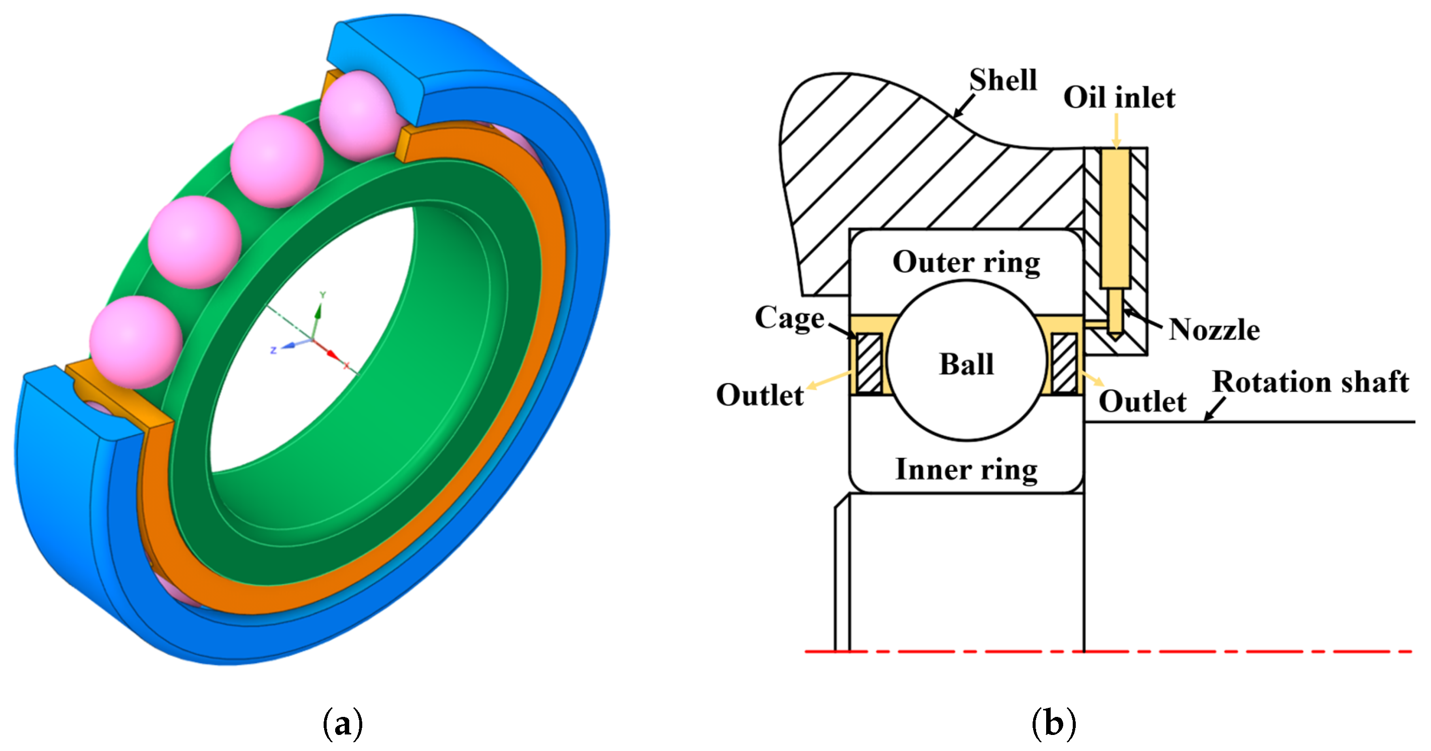
Figure 1. Geometric structure and oil injection mechanism of bearings: (a) Schematic diagram of bearing structure. (b) Oil injection lubrication method for bearings.
Machines 13 00678 g001
Figure 2. Bearing churning loss test system: (a) Churning power loss test bench. (b) Schematic diagram of power transmission path.
Machines 13 00678 g002
Figure 3. Experimental results: (a) Churning resistance torque at various rotational speeds. (b) Churning power loss at various rotational speeds.
Machines 13 00678 g003
Figure 4. Computational Domain Partitioning for Rolling Bearings Using SMM.
Machines 13 00678 g004
Figure 5. Principle of Time Step Estimation for SMM.
Machines 13 00678 g005
Figure 6. Spatial distribution of oil volume fraction in FVM model.
Machines 13 00678 g006
Figure 7. Circumferential distribution of oil volume fraction in FVM model.
Machines 13 00678 g007
Figure 8. Observability of Lubricating Oil Films in Rolling Bearings via FVM Simulations.
Machines 13 00678 g008
Figure 9. Schematic diagram of particle influence radius and kernel function.
Machines 13 00678 g009
Figure 10. MPS simulation results of oil distribution in rolling bearings at different speeds.
Machines 13 00678 g010
Figure 11. Prediction and experimental results of churning power loss.
Machines 13 00678 g011
Figure 12. CFD simulation strategy decision flowchart for two-phase flow analysis of bearing lubrication.
Machines 13 00678 g012
Table 1. The structural dimension parameters of the bearing.
DenotationSymbolValue
Inner diameter (mm)d60
Outer diameter (mm)D110
Width (mm)B22
Ball diameter (mm) D b a l l 4
Number of ballsZ14
Nozzle diameter (mm) d N 1.5
Table 2. The parameters of lubricating oil.
DenotationSymbolValue
Density ( kg / m 3 ) ρ 920
Dynamic viscosity (Pa· s) μ 0.0074
Oil temperature ( ° C )T60
Table 3. The key parameters of the test bearing.
DenotationSymbolValue
Inner diameter (mm)d30
Outer diameter (mm)D62
Width (mm)B16
Ball diameter (mm) D b a l l 4.76
Number of ballsZ9
Nozzle diameter (mm) d N 1.5
Table 4. The parameters of test lubricating oil.
DenotationSymbolValue
Density ( kg / m 3 ) ρ 853
Dynamic viscosity (Pa· s) μ 0.16
Oil temperature ( ° C )T20
Table 5. Comparison of computational efficiency between FVM and MPS models.
ModelTime Consumption (h)
FVM11
MPS14–18
Disclaimer/Publisher’s Note: The statements, opinions and data contained in all publications are solely those of the individual author(s) and contributor(s) and not of MDPI and/or the editor(s). MDPI and/or the editor(s) disclaim responsibility for any injury to people or property resulting from any ideas, methods, instructions or products referred to in the content.