Article

Optimal Dimensional Synthesis of Ackermann and Watt-I Six-Bar Steering Mechanisms for Two-Axle Four-Wheeled Vehicles

by
Yaw-Hong Kang
1,
Da-Chen Pang
1,2,* and
Dong-Han Zheng
1
1
Department of Mechanical Engineering, National Kaohsiung University of Science and Technology, 415 Jiangong Rd., Sanmin District, Kaohsiung 80778, Taiwan
2
Department of Vehicle Engineering, National Kaohsiung University of Science and Technology, 58 Shenzhong Rd., Yanchao District, Kaohsiung 82444, Taiwan
*
Author to whom correspondence should be addressed.
Machines 2025, 13(7), 589; https://doi.org/10.3390/machines13070589
Submission received: 8 June 2025 / Revised: 28 June 2025 / Accepted: 4 July 2025 / Published: 7 July 2025
(This article belongs to the Special Issue The Kinematics and Dynamics of Mechanisms and Robots)

Abstract

This study investigates the dimensional synthesis of steering mechanisms for front-wheel-drive, two-axle, four-wheeled vehicles using two metaheuristic optimization algorithms: Differential Evolution with golden ratio (DE-gr) and Improved Particle Swarm Optimization (IPSO). The vehicle under consideration has a track-to-wheelbase ratio of 0.5 and an inner wheel steering angle of 70 degrees. The mechanisms synthesized include the Ackermann steering mechanism and two variants (Type I and Type II) of the Watt-I six-bar steering mechanisms, also known as central-lever steering mechanisms. To ensure accurate steering and minimize tire wear during cornering, adherence to the Ackermann steering condition is enforced. The objective function combines the mean squared structural error at selected steering positions with a penalty term for violations of the Grashoff inequality constraint. Each optimization run involved 100 or 200 iterations, with numerical experiments repeated 100 times to ensure robustness. Kinematic simulations were conducted in ADAMS v2015 to visualize and validate the synthesized mechanisms. Performance was evaluated based on maximum structural error (steering accuracy) and mechanical advantage (transmission efficiency). The results indicate that the optimized Watt-I six-bar steering mechanisms outperform the Ackermann mechanism in terms of steering accuracy. Among the Watt-I variants, the Type II designs demonstrated superior performance and convergence precision compared to the Type I designs, as well as improved results compared to prior studies. Additionally, the optimal Type I-2 and Type II-2 mechanisms consist of two symmetric Grashof mechanisms, can be classified as non-Ackermann-like steering mechanisms. Both optimization methods proved easy to implement and showed reliable, efficient convergence. The DE-gr algorithm exhibited slightly superior overall performance, achieving optimal solutions in seven cases compared to four for the IPSO method.

1. Introduction

The steering system of an automobile is a fundamental component that directly influences the vehicle’s maneuverability and overall driving performance. The precision of the steering mechanism plays a vital role in determining how the vehicle responds to driver input, especially while cornering. An accurate and responsive steering system enhances handling, making the vehicle easier and safer to control under various driving conditions. Furthermore, poor steering accuracy can lead to uneven or excessive tire wear, reducing tire life and increasing maintenance costs. It can also negatively affect the dynamic stability of the vehicle, particularly at high speeds or during sudden maneuvers, increasing the risk of accidents. Therefore, the design and maintenance of the steering system are critical for ensuring optimal vehicle performance, safety, and comfort. The steering mechanism of a front-wheel-drive, two-axle, four-wheeled vehicle is designed so that the axes of the steerable front wheels and the rear wheels instantaneously intersect at a single point during steering. This design, known as the Ackermann condition, minimizes tire wear and enhances turning stability by ensuring all wheels roll without lateral slip during cornering. The traditional Ackermann steering mechanism is essentially a Non-Grashof four-bar linkage with equal-length steering arms [1]. It functions as a four-bar function generator, where the output and input steering angles approximate the geometric relationship prescribed by the Ackermann condition at selected positions [2]. However, in practice, no steering mechanism can perfectly satisfy the Ackermann condition across the full range of steering angles. As a result, steering mechanisms are typically designed to minimize the overall deviation from this ideal condition throughout the steering range. Numerous researchers have focused on optimizing these steering mechanisms to minimize the structural error between the ideal and actual steering angles of the outer front wheel during motion. To address these challenges, various types of steering mechanisms have been proposed for both vehicles and mobile robots. These include non-circular gear steering [3,4], differential gear steering [5], pure rolling steering [6], and several linkage-based steering mechanisms [2,7,8,9,10,11,12,13,14,15,16,17,18,19,20,21,22,23,24,25,26,27,28,29,30,31,32,33]. Among the linkage-based systems are rack-and-pinion mechanisms [7,8,9], the Ackermann steering mechanism [2,10,11,12,13,14], the Ackermann type steering mechanism [15], the Watt-I six-bar steering mechanisms (also known as the central-lever six-bar mechanisms) [11,16,17,18,19,20,21,22,23,24,25,26,27,28,29,30], and other multi-bar mechanisms [31,32,33].
The Watt-I six-bar steering mechanism offers a promising solution by incorporating two symmetric four-bar linkages, thereby enhancing the approximation of the Ackermann steering condition. This configuration provides greater flexibility in meeting desired output function and performance criteria while maintaining mechanical simplicity and compactness. However, the design and dimensional synthesis of Watt-I six-bar steering mechanisms present significant challenges. Conventional design approaches—such as graphical synthesis, empirical trial-and-error, or basic numerical techniques—often suffer from limited accuracy, low efficiency, and an inability to handle complex, nonlinear design spaces. These limitations make it difficult to achieve optimal steering performance, particularly when multiple competing objectives must be considered. This article investigates the optimal dimensional synthesis of linkage-type steering mechanisms, including the Ackermann steering mechanism and two variants (Type I and Type II) of the Watt-I six-bar steering mechanisms, also known as central-lever steering mechanisms. While a substantial body of literature exists on the synthesis of the Ackermann mechanism, this study places particular emphasis on the formulation, analysis, and optimization of Watt-I six-bar steering mechanisms, which offer greater design flexibility and the potential for improved steering accuracy.
Different optimization methods have been applied to the optimal dimensional synthesis of central-lever six-bar steering mechanisms. Fahey and Huston [31] proposed a Fahey eight-member steering mechanism (FEMM) as an alternative to the Ackermann-type steering linkage for a vehicle with a track-to-wheelbase ratio of 0.6 and an inner wheel steering angle of 61 degrees. Dimensional synthesis of the FEMM was carried out using a progressive numerical iterative method, initiated from an estimated guess, to minimize structural error and enhance end-divergent behavior over an extended steering range. The resulting optimal FEMM achieved a maximum structural error of just 0.03 degrees. Carcaterra et al. [5] proposed a differential steering mechanism derived from a six-bar linkage, augmented by a differential mechanism and a higher pair. The steering system converts a single input into two outputs, ensuring compliance with the correct steering condition. Yao and Angeles [11] proposed a computational kinematics approach based on elimination procedures to synthesize a steering four-bar mechanism, aiming to minimize the root-mean-square of the structural error over the steering motion range. However, the global optimum obtained from the locally optimal solutions exhibited a dimensional unbalance issue. To address this drawback, they employed a kinematically equivalent focal six-bar mechanism, which is classified as a Type II-2 Watt-I steering mechanism. Simionescu and Smith [16] proposed several parametric design charts involving four design parameters for various trailing and leading central-lever six-bar steering mechanisms. These charts were produced by Brent’s algorithm and are intended to assist automotive engineers in identifying optimal central-lever six-bar steering mechanisms that minimize steering error. Pramanik [17] proposed a central-lever six-bar mechanism for automobile steering, designed for a vehicle with a track-to-wheelbase ratio of 0.6 and an inner wheel steering angle of 61 degrees. Dimensional synthesis was carried out using the Newton–Raphson method to solve the correction vector of three design parameters, with the process initiated a geometrically estimated guess and iteratively update the parameters to achieve five precision points. The optimized mechanism yielded a maximum structural error of 0.301 degrees. Its performance was intermediate between that of the conventional Ackermann steering mechanism and the Fahey eight-member steering mechanism. Gautam and Awadhiya [18] proposed a modified Ackermann steering mechanism (leading central-lever six-bar steering mechanism) for automotive steering. Four design parameters were determined by solving three nonlinear equations from three selected precision points. The synthesized mechanism was compared with the Ackermann, Fahey eight-member, and Pramanik six-member steering mechanisms, revealing a maximum steering error of about 0.4 degrees and improved end-divergent behavior. Soh and McCarthy [19] proposed a 14 bar steering linkage comprising a Watt-I (referred to as Watt-II in their paper) six-bar mechanism and its mirror-image at the front left and right wheels, interconnected by a driving link and two coupler links. The steering linkage achieves five Ackermann steering positions and allows the outer wheel to respond to roll-over moments during cornering. De-Juan and Sancibrian [20] employed a local optimization method based on exact gradient determination and an initial guess solution to synthesize three types of steering mechanisms for road vehicles: rack-and-pinion, four-bar, and six-bar mechanisms. The objective function was formulated in terms of structural error, which included both Ackermann error and transmission angle error. For the four-bar mechanism, the optimal design resulted in a maximum structural error of 1.15 degrees. In the six-bar mechanism design, five design variables were considered, and the optimal mechanism achieved a maximum structural error of 1.03 degrees. However, the optimal solutions corresponding to an initial steering input angle near zero degrees and a comparatively large link length were found to be unreasonable. Peñuñuri et al. [21] applied the Differential Evolution (DE) optimization algorithm to synthesize a Watt-I six-bar steering mechanism that satisfies the Ackermann steering condition. Using the mean squared steering error as the objective function, the optimized mechanism achieved a maximum steering error of 0.867 degrees. De-Juan et al. [8] developed a systematic gradient-based optimization method with an initial guess solution to optimize four planar steering mechanisms used in road vehicles: rack-and-pinion, four-bar, six-bar, and double four-bar mechanisms. The optimization involved solving highly nonlinear equations derived from the Jacobian matrix during the structural error minimization process. These equations were solved approximately using a Taylor series expansion. The Ackermann mechanism, synthesized with two design variables, exhibited a maximum structural error of 1.64 degrees, while the central-lever (leading-mixed) six-bar steering mechanism, using five design variables, yielding a significantly lower structural error of 0.021 degrees. Pramanik et al. [22] applied the Hooke and Jeeves optimization method to synthesize the Ackermann, rack-and-pinion, and central-lever steering mechanisms, and their performances were compared. The results indicated that the rack-and-pinion steering mechanism exhibited the lowest steering error and least mechanical advantage, whereas the central-lever mechanism achieved the best transmission angle and mechanical advantage, but with the highest steering error of 1.4 degrees. Pramanik [23] synthesized a trailing six-member automotive steering mechanism using the Newton–Raphson method, achieving five precision points through iterative refinement. The optimized mechanism reduced the maximum steering error to 0.715 degrees and eliminated end-divergent behavior, offering a viable alternative to the Ackermann mechanism. Wang and Dai [24] presented two symmetrical planar central-lever six-bar mechanisms as the front two-axle steering systems. The dimensional synthesis of these mechanisms was carried out using the Newton–Raphson iterative method to solve the nonlinear equations. The resulting optimal steering mechanisms for the first and second axles achieved maximum structural errors of 0.7934 degrees and 0.1057 degrees, respectively. Romero-Núñez and Villalba [25] applied the Genetic Algorithm (GA) to optimize a six-bar steering mechanism formulated with natural coordinates. The optimized mechanism, based on six design parameters, yielded a maximum steering error of 0.9 degrees. Zhou et al. [26] designed five Watt-II central-arm six-bar linkages to serve as the steering mechanisms for a five-axle multi-wheeled heavy vehicle. Using three design variables, the central-arm six-bar steering mechanisms were synthesized with Broyden’s iterative algorithm, starting from an appropriate initial guess. The kinematic simulation of the optimized mechanisms was performed using ADAMS. Pramanik and Thipse [27] synthesized a central-lever steering mechanism for a four-wheel vehicle using the Hooke and Jeeves optimization method, based on an initial solution estimate. The mechanism, comprising two identical crossed four-bar linkages in series, allowed for the optimization of a single crossed four-bar linkage with two design parameters. The resulting design achieved reduced steering error, improved pressure angles, and enhanced mechanical advantage. Romero-Nuñez et al. [28] performed the optimal synthesis of a central-lever steering linkage using five natural coordinates as design variables. The kinematic analysis was solved using the Newton–Raphson method based on an initial guess solution. The multi-objective optimization was carried out with the interior-point algorithm from the MATLAB toolbox, yielding an optimal mechanism with a maximum steering error of 0.016 degrees. Pramanik [29] developed foldable steering mechanisms for an agricultural harvesting machine with two track-to-wheelbase ratios, with one double the values of the other. The design integrates two or four crossed four-bar mechanisms (CFBMs) depending on operational mode. A single CFBM, synthesized using two design parameters and two precision points, was solved via the Newton–Raphson method, achieving a maximum steering error of 0.27° over a 70° inner wheel steering range. For the transport mode, a central-lever six-bar mechanism comprising two CFBMs in series was used, while for the harvesting mode, a compound mechanism of four CFBMs in series was deployed. Tuleshoy et al. [30] presented a modified two-circuit Ackermann steering mechanism, comprising two identical four-bar linkages, for a transport mobile robot. Four design parameters were synthesized, and the mechanism’s kinematic analysis was performed using the ASIAN-2014 software package.
This study aims to employ advanced metaheuristic optimization techniques, specifically the Differential Evolution with golden ratio (DE-gr) and the Improved Particle Swarm Optimization (IPSO) algorithms, to synthesize the dimensional parameters of the Ackermann steering mechanism and two variants (Type I and Type II) of the Watt-I six-bar steering mechanisms used in front-wheel-drive, two-axle, four-wheeled vehicles. Unlike traditional optimization techniques such as least squares minimization, sequential quadratic programming (SQP), gradient-based methods, the Newton–Raphson method, and the Hooke–Jeeves method, these metaheuristic algorithms offer distinct advantages. Most notably, they do not require the computation of derivatives of the objective function or the provision of an appropriate initial guess solution. This characteristic significantly simplifies the optimization process and enhances computational efficiency, making them particularly well-suited for solving the optimal dimensional synthesis of steering mechanisms [34], where nonlinear, multi-variable design spaces are common. DE-gr and IPSO are both well-recognized for their ease of implementation, rapid convergence, and high accuracy in solving high-dimensional, nonlinear optimization problems [35,36]. By systematically applying them to the dimensional synthesis of various types of Watt-I six-bar steering mechanisms, this research significantly improves the steering accuracy, transmission efficiency, and practical feasibility of the resulting designs.
The design parameters of the steering mechanisms must closely adhere to the Ackermann steering principle throughout the steering process. The objective function to be minimized comprises the mean of the squared structural errors at selected steering angles, along with a penalty function enforcing inequality constraints based on the Grashoff’s criterion. In addition to optimizing the steering mechanisms, this study compares the performance of the two optimization methods in terms of convergence speed and solution accuracy. The kinematic performance of the optimized mechanisms is evaluated using key indicators such as transmission angle, mechanical advantage, and maximum structural error. The optimization algorithms were implemented in MATLAB, while kinematic simulations were performed using the multi-body dynamic software ADAMS v2015 to visualize and validate the steering performance and practical feasibility of the synthesized mechanisms.
The remainder of this article is organized as follows: Section 2 introduces the Ackermann steering principle and presents a position analysis of the two planar linkage-type steering mechanisms to be synthesized in this study. Section 3 describes the fundamental concepts and flowcharts of the two metaheuristic optimization algorithms employed: Differential Evolution with golden ratio (DE-gr) and Improved Particle Swarm Optimization (IPSO). Section 4 details the results of the optimal dimensional synthesis for twelve design cases, comparing the convergence speed, solution accuracy, and maximum structural error of the optimal mechanisms produced by both algorithms. Additionally, it evaluates the mechanical advantage of the best-performing mechanism and includes ADAMS simulations to visualize and validate the kinematic behavior of the optimized designs. Finally, Section 5 concludes the study by summarizing the key findings and potential applications

2. Ackermann Principle and Steering Angular Position Analysis of Linkage-Type Steering Mechanisms

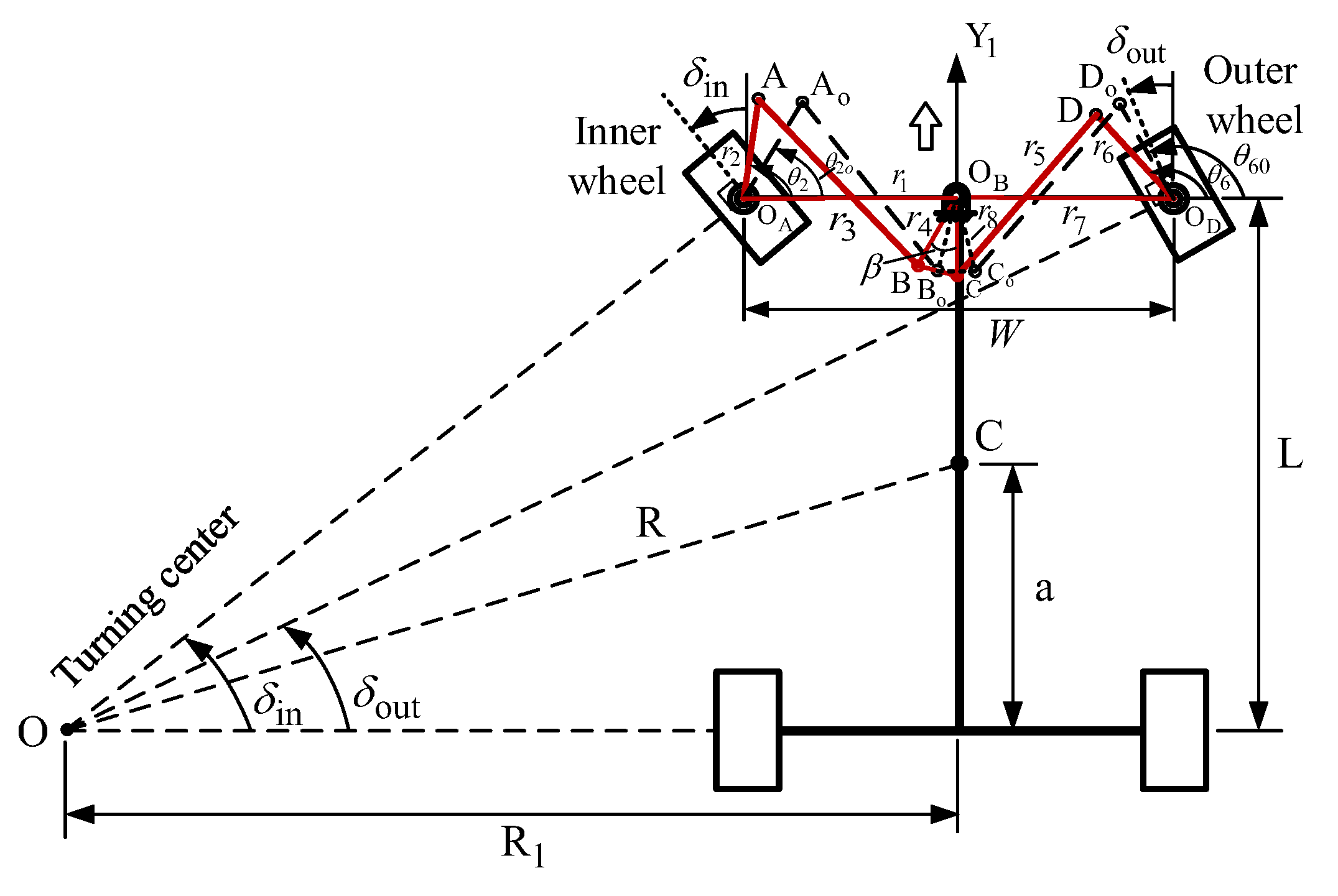
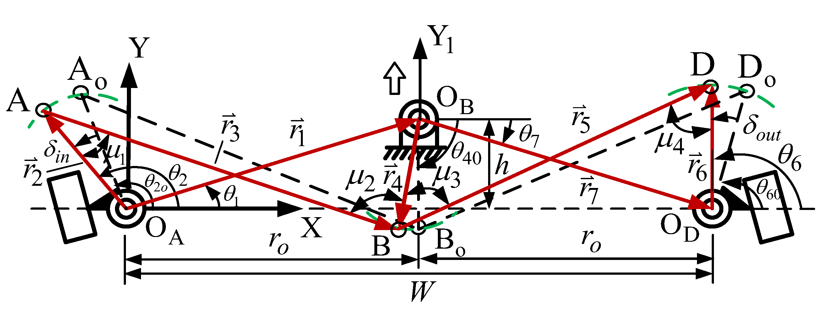
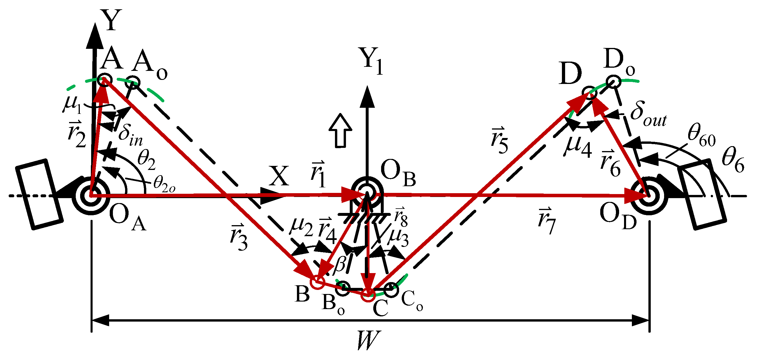
Figure 1 and Figure 2 illustrate the schematic diagrams of the Ackermann steering mechanism and the Watt-I six-bar steering mechanism, respectively, depicting both the straight-ahead driving condition (dashed lines) and the left-turning condition (solid lines) of a front-wheel-drive road vehicle. The Ackermann steering mechanism comprises a planar four-bar linkage with four revolute joints, while the Watt-I six-bar steering mechanisms consist of either seven revolute joints (e.g., Type I-1, I-3, II-1, II-3) or five revolute joints and one triple joint (e.g., Type I-2, II-2). According to Grubler’s criterion [37] for the degree of freedom (dof) of planar mechanisms, F = 3(N − 1) − 2J1 − J2, where N is the number of links, J1 is the number of 1-dof joints, and J2 is the number of 2-dof joints. For the Ackermann and Watt-I mechanisms, we obtain F = 3(4 − 1) − 2(4) = 1 and F = 3(6 − 1) − 2(7) = 1, respectively. Thus, both steering mechanisms have one degree of freedom, allowing a single steering input to produce a determinate steering output motion.
The steering mechanisms are designed to be symmetric along the longitudinal plane of vehicle with an equal length of the input and output links (steering arms) for turning left and right under the same conditions. In the figures, the bold white arrow indicates the direction of straight-line vehicle motion. During a left turn, the steering angle of the inner front wheel must be greater than that of the outer front wheel, and vice versa for a right turn. This ensures that the extended axes of the front wheels intersect at a common point on the centerline of the rear axle, known as the instantaneous center (IC). When the vehicle turns slowly, this alignment allows for smooth cornering around the IC without wheel slip, thereby reducing friction and excessive tire wear. This geometric condition, which governs the relative steering angles of the inner and outer wheels, is known as the Ackermann condition or Ackermann steering principle. It satisfies the following geometric relationship:
cot δ o u t cot δ i n = W L
Here, δin and δout denote the steering angles of the front inner and outer wheels, respectively. W represents the track width (the distance between the two steerable wheels), and L is the wheelbase (the distance between the front and rear axles). As illustrated in Figure 1 and Figure 2, point C denotes the mass center of the vehicle, point O is the instantaneous center of rotation (IC), and R is the instantaneous turning radius, defined as the distance CO. Parameter a represents the distance from the mass center C to the rear axle, and R1 is the perpendicular distance from the turning center O to the vehicle’s central longitudinal axis. The instantaneous turning radius R can be calculated as follows:
R = a 2 + L 2 cot 2 δ
in which
cot δ = cot δ i n + cot δ o u t 2
and
cot δ i n = R 1 W 2 L , cot δ o u t = R 1 + W 2 L
Because the inner and outer front wheels exhibit symmetric behavior when the vehicle turns left and right, respectively, the range of steering motion for both wheels is designed symmetrically within a specific angular region. δ i n min δ i n δ i n max and δ o u t min δ o u t δ o u t max , where δ o u t min = δ i n max , δ o u t max = δ i n min .

2.1. The Ackermann Steering Mechanism

The Ackermann steering mechanism (also known as the steering trapezoidal mechanism), shown in Figure 3, features equal-length input and output links. The mechanism can be configured in either a trailing configuration (Figure 3a) or a leading configuration (Figure 3b) [13]. In this study, the trailing type was selected as the design example. The X-axis of the coordinate system was aligned with the axle of the front wheels, while the Y-axis pointed rearward. The dotted line (OA-AO-BO-OB) represents the initial position of the steering mechanism when the vehicle is moving straight ahead. At this position, link 3 is parallel to link 1, the angle between the input link 2 and the X-axis is θ 20 , and the angle between the output link 4 and the X-axis is θ 40 , θ 40 = π θ 20 . The red solid line (OA-A-B-OB) illustrates the phase of the mechanism when the vehicle’s front inner wheel turns at an angle δ i n , with the corresponding outer wheel turning at an angle δ o u t . Both steering angles are measured as positive when turning counterclockwise (CCW). In this phase, the angle between the input link 2 and the X-axis is θ2, and the angle between the output link 4 and the X-axis is θ4. The angular positions of both the input and output links are measured as positive when rotating clockwise (CW).
The lengths of link 1 and link 3 are r 1 = W , r 3 = W 2 r 2 cos θ 20 , respectively. For the design of the Ackermann steering mechanism, only two design parameters are required: the length of input link r 2 and the initial input angle θ 20 . The design vector can be expressed as X = [ x 1 , x 2 ] T = [ r 2 , θ 20 ] T .
From Figure 3a
θ 2 = θ 20 δ i n , θ 40 = π θ 20
Hence,
δ o u t = θ 40 θ 4 = π θ 20 θ 4
As shown in Figure 3a, the motion parameters of the four-bar mechanism are defined by the vectors in the figure, and the corresponding vector loop equation is given by the following:
r 2 + r 3 r 4 r 1 = 0
Taking the inner product of the vectors gives the following:
r 3 r 3 = ( r 1 + r 4 r 2 ) ( r 1 + r 4 r 2 )
After expansion and rearrangement, the equation can be written as follows:
A cos θ 4 + B sin θ 4 = C
In which
A = 2 r 4 r 1 cos θ 1 r 2 cos θ 2 B = 2 r 4 ( r 1 sin θ 1 r 2 sin θ 2 ) C = r 3 2 r 1 2 r 2 2 r 4 2 + 2 r 1 r 2 cos ( θ 2 θ 1 )
Here, θ 1 = 0 ° . By applying the following half-angle formulas for sine and cosine functions in Equation (9).
sin θ 4 = 2 tan θ 4 2 1 + tan 2 θ 4 2 , cos θ 4 = 1 tan 2 θ 4 2 1 + tan 2 θ 4 2
After rearranging and solving the resulting quadratic equation in terms of tan(θ4/2), the output angle θ4 can be expressed as follows:
θ 4 = 2 tan 1 ( B ± A 2 + B 2 C 2 A + C )
In the above equation, the ‘±’ sign indicates the two possible assembly configurations of the four-bar mechanism. The ‘+’ sign corresponds to the configuration referred to as Assembly I, as shown in the steering mechanism diagram, while the ‘−’ sign corresponds to the alternate configuration, referred to as Assembly II.
The transmission angle, μ, of the four-bar linkage is a key index that characterizes the transmission performance of the steering mechanism. For acceptable performance, it is generally recommended that the maximum deviation from 90° does not exceed 50°, i.e., 40 ° μ 140 ° [37].
μ 1 = cos 1 r 2 2 + r 3 2 r 1 2 r 4 2 2 r 1 r 4 cos θ 4 2 r 2 r 3
μ 2 = cos 1 r 3 2 + r 4 2 r 1 2 r 2 2 + 2 r 1 r 2 cos θ 2 2 r 3 r 4

2.2. The Watt-I Six-Bar Steering Mechanism

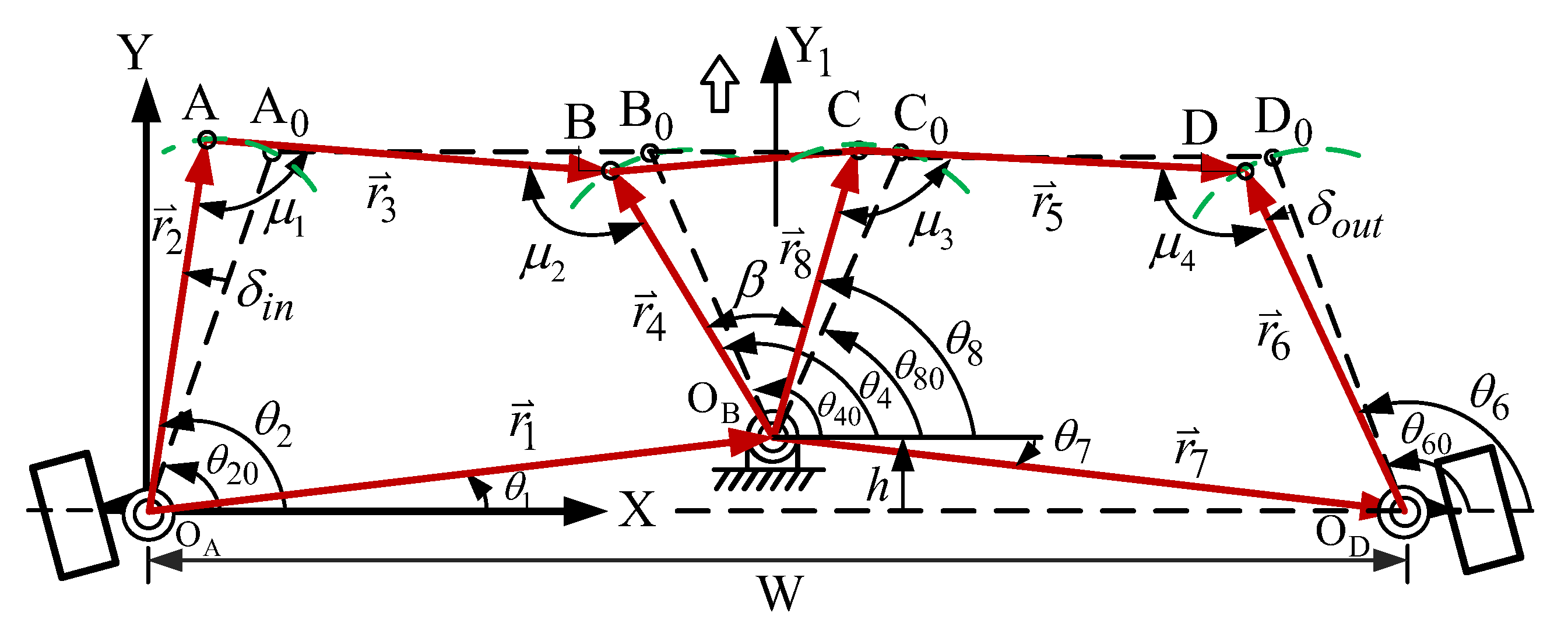
The mechanism skeleton of the general Watt-I six-bar steering mechanism [37] is shown in Figure 4. It consists of two identical four-bar linkages arranged symmetrically with respect to the vehicle’s longitudinal axis (Y1). The distance between the fixed central pivot point OB and the X-axis is denoted by h, and the inclined angle between the two constituent four-bar linkages is represented by β. Based on the assembly configuration of the first consistent four-bar linkage, the Watt-I six-bar steering mechanism can be classified into two primary types: Type I and Type II. Furthermore, based on whether the design parameters h and β are zero or non-zero, whether link length r4 is treated as an independent design variable, and some specified initial configurations, the mechanism can be classified into eleven distinct design cases, as illustrated below.

2.2.1. Type I of the Watt-I Six-Bar Steering Mechanism

The Type I Watt-I six-bar steering mechanism includes six distinct design cases, outlined as follows:
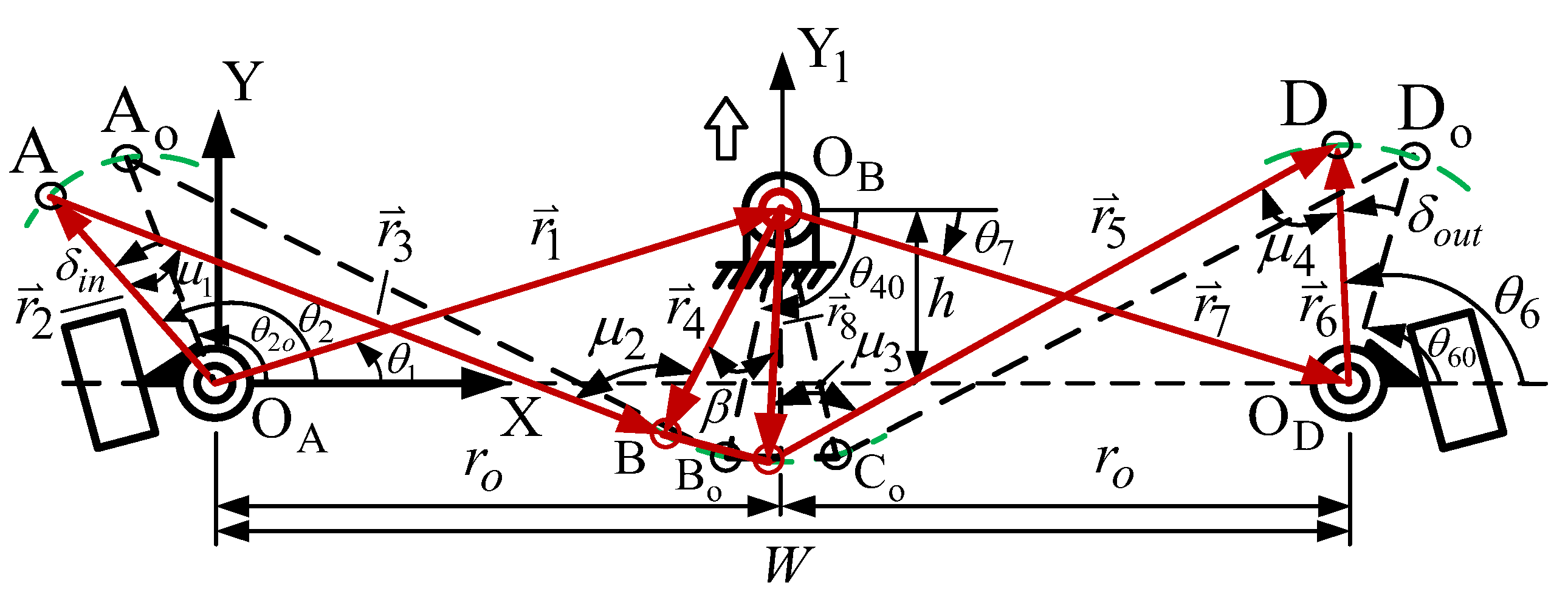
(1) Type I-1 ( h 0 , β 0 ) : As shown in Figure 4, the general Watt-I six-bar steering mechanism is commonly referred to as the leading central-lever steering mechanism. The link lengths satisfy the following geometric relationships: r 6 = r 2 ,   r 8 = r 4 , r 5 = r 3 , r 7 = r 1 , θ 7 = θ 1 . The X-axis of the X-Y coordinate system is aligned with the axle of the front wheels. The dashed lines in the figure represent the initial configuration (straight-ahead position), where θ 60 = π θ 20 . The solid lines represent the steering condition, when the inner wheel turns by an angle δin (e.g., during a left turn), resulting in a corresponding outer wheel angle δout. The angular positions of the input and output links are θ2 and θ6, respectively. All steering and link angles are defined as positive in the counterclockwise (CCW) direction. Type I-1 consists of two variants, referred to as Type I-1A and Type I-1B, respectively. (a) Type I-1A ( r 4 = r 2 ) : With equal-length steering links, this case contains five design variables. The design vector is expressed as X = [ x 1 , x 2 , x 3 , x 4 , x 5 ] T = [ r 2 , r 3 , h , β , θ 20 ] T . (b) Type I-1B ( r 4 r 2 ) : With the link length r4 treated as an independent design variable, this case contains six design variables. The design vector is expressed as X = [ x 1 , x 2 , x 3 , x 4 , x 5 , x 6 ] T = [ r 2 , r 3 , r 4 , h , β , θ 20 ] T . (2) Type I-2 ( h 0 , β = 0 ) ( r 4 r 2 ) : As illustrated in Figure 5, this configuration includes a triple joint at point Bo and initially satisfies the following geometric relationships: r 6 = r 2 ,   r 5 = r 3 ,   r 7 = r 1 ,   r 0 = W 2 ; θ 40 = π 2 ,   θ 7 = θ 1 ,     θ 60 = π θ 20 . This configuration includes five design variables, and its design vector is expressed as X = [ x 1 , x 2 , x 3 , x 4 , x 5 ] T = [ r 2 , r 3 , r 4 , h , θ 20 ] T . Type I-2 can be regarded as a special case of Type I-1B with additional geometric constraints: β = 0 . (3) Type I-3 ( h = 0 , β 0 ) : As shown in Figure 6, this configuration features link lengths with the following relationships: r 6 = r 2 ,     r 8 = r 4 , r 5 = r 3 , r 7 = r 1 = W 2 ; θ 7 = θ 1 = 0 , θ 20 = θ 80 , θ 60 = θ 40 ,   θ 40 = π θ 20 . This type includes three variants, designated as Type I-3A, Type I-3B, and Type I-3C, respectively. (a) Type I-3A ( r 4 = r 2 ) : With equal-length steering links, this design case has four design variables; the design vector is expressed as X = [ x 1 , x 2 , x 3 , x 4 ] T = [ r 2 , r 3 , β , θ 20 ] T . (b) Type I-3B ( r 4 r 2 ) : With the link length r4 treated as an independent design variable, this design case has five design variables; the design vector is expressed as X = [ x 1 , x 2 , x 3 , x 4 , x 5 ] T = [ r 2 , r 3 , r 4 , β , θ 20 ] T . (c) Type I-3C ( r 4 = r 2 ) : In this case, with equal-length steering links and the initial positions of links 3 and 5 being parallel to the fixed link (links 1 and 7), θ 3 o = θ 5 o = 0 ° ; hence, θ 40 = π θ 20 , θ 80 = θ 40 β , β = π 2 θ 20 , and r 3 = r 1 2 r 2 cos θ 20 . This constraint reduces the number of design variables to two. The design vector is X = [ x 1 , x 2 ] T = [ r 2 , θ 20 ] T . Type I-3C can be considered a special case of Type I-3A under the given initial constraints. In this case, the steering mechanism can be regarded as consisting of two identical Ackermann steering mechanisms connected in series, with design parameters that are identical to those of the traditional Ackermann mechanism.

2.2.2. Type II of the Watt-I Six-Bar Steering Mechanism

The Type II Watt-I six-bar steering mechanism comprises five distinct design cases, described as follows:
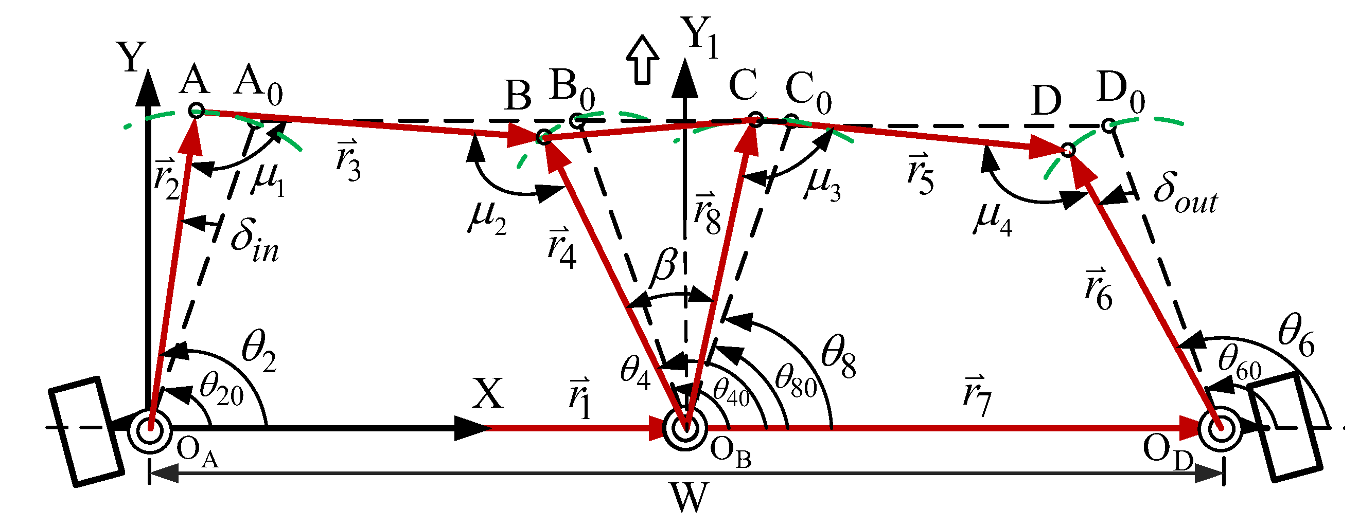
(1) Type II-1 ( h 0 , β 0 ) : As illustrated in Figure 7, this configuration satisfies the following geometric relationships: r 6 = r 2 ,   r 5 = r 3 ,   r 8 = r 4 ,   r 7 = r 1 ,   r 0 = W 2 ,   θ 7 = θ 1 . The link length of r4 defines two subcases: (a) Type II-1A ( r 4 = r 2 ) : With equal-length steering links, this case involves five design variables, and the design vector is expressed as X = [ x 1 , x 2 , x 3 , x 4 , x 5 ] T = [ r 2 , r 3 , h , β , θ 20 ] T . (b) Type II-1B ( r 4 r 2 ) : With the link length r4 treated as an independent design variable, this case includes six design variables. The design vector is expressed as X = [ x 1 , x 2 , x 3 , x 4 , x 5 , x 6 ] T = [ r 2 , r 3 , r 4 , h , β , θ 20 ] T . (2) Type II-2 ( h 0 , β = 0 ) ( r 4 r 2 ) : As shown in Figure 8, this configuration includes a triple joint at point Bo and initially satisfies the following geometric relationships: r 6 = r 2 ,   r 5 = r 3 , r 7 = r 1 ,   r 0 = W 2 ,     θ 40 = π 2 ,   θ 7 = θ 1 ,   θ 60 = π θ 20 . With link length r4 treated as an independent design variable, this case includes five design variables, with the design vector expressed as X = [ x 1 , x 2 , x 3 , x 4 , x 5 ] T = [ r 2 , r 3 , r 4 , h , θ 20 ] T . In cases of Type I-1, Type I-2, Type II-1 and Type II-2, if parameter h < 0, the central pivot OB lies below the X-axis. This configuration is commonly referred to as the trailing central-lever steering mechanism [16]. (3) Type II-3 ( h = 0 , β 0 ) : As shown in Figure 9, the geometry of this configuration satisfies r 6 = r 2 ,     r 8 = r 4 , r 5 = r 3 , r 7 = r 1 = W 2 , θ 7 = θ 1 = 0 . This case includes two subcases based on whether r4 is fixed or a design variable, which are denoted as Type II-3A and Type II-3B, respectively. (a) Type II-3A ( r 4 = r 2 ) : The configuration has four design variables. The design vector is expressed as X = [ x 1 , x 2 , x 3 , x 4 ] T = [ r 2 , r 3 , β , θ 20 ] T . (b) Type II-3B ( r 4 r 2 ) : With link length r4 treated as an independent variable, this case has five design variables. The design vector is expressed as X = [ x 1 , x 2 , x 3 , x 4 , x 5 ] T = [ r 2 , r 3 , r 4 , β , θ 20 ] T .
For ease of discussion, in the following sections, Table 1 provides a summary of the design parameters, design vectors, and geometric conditions for each design case of the two variants of Watt-I six-bar steering mechanism. Detailed geometric constraints for the optimal synthesis of each steering mechanism will be presented within the corresponding case discussions.

2.3. Position Analysis of the Watt-I Six-Bar Mechanism

For a position analysis of each type of Watt-I six-bar mechanism, the vectors are defined by the red arrows shown in Figure 4, Figure 5, Figure 6, Figure 7, Figure 8 and Figure 9. To illustrate the steering angular position analysis process, the Type I-1 Watt-I six-bar mechanism is used as a representative example.
The vector loop equations in the two independent loops can be expressed as follows:
r 2 + r 3 r 4 r 1 = 0 r 8 + r 5 r 6 r 7 = 0
The output angular position θ 4 of the first loop is derived as in Equation (12), and the output angular position θ 6 of the second loop can be derived similarly and expressed as follows:
θ 6 = 2 tan 1 ( B 1 ± A 1 2 + B 1 2 C 1 2 A 1 + C 1 )
In which
A 1 = 2 r 6 ( r 7 cos θ 7 r 8 cos θ 8 ) B 1 = 2 r 6 ( r 7 sin θ 7 r 8 sin θ 8 ) C 1 = r 5 2 r 6 2 r 7 2 r 8 2 + 2 r 7 r 8 cos ( θ 8 θ 7 ) θ 8 = θ 4 β
In Equation (16), the ‘+’ sign is used for the second loop assembly configuration shown in Figure 4.
δ i n = θ 2 θ 20 , θ 60 = π θ 20
Hence,
δ o u t = θ 6 θ 60 = θ 6 π + θ 20
The four transmission angles ( μ 1 , μ 2 , μ 3 , μ 4 ) can be expressed as follows:
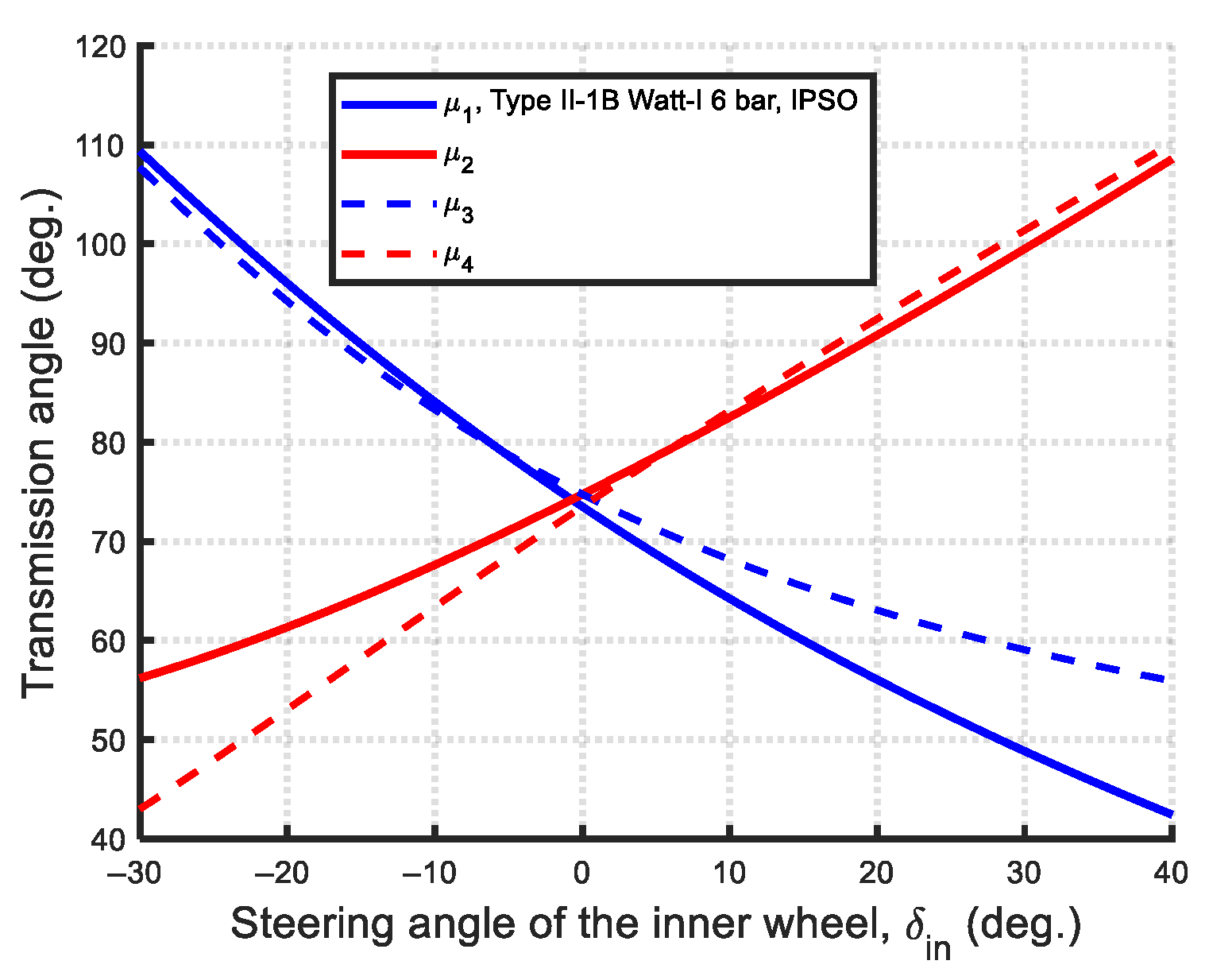
μ 1 = cos 1 r 2 2 + r 3 2 r 1 2 r 4 2 2 r 1 r 4 cos ( θ 4 θ 1 ) 2 r 2 r 3 μ 2 = cos 1 r 3 2 + r 4 2 r 1 2 r 2 2 + 2 r 1 r 2 cos ( θ 2 θ 1 ) 2 r 3 r 4 μ 3 = cos 1 r 5 2 + r 8 2 r 6 2 r 7 2 2 r 6 r 7 cos ( θ 6 θ 7 ) 2 r 5 r 8 μ 4 = cos 1 r 5 2 + r 6 2 r 7 2 r 8 2 + 2 r 7 r 8 cos ( θ 8 θ 7 ) 2 r 5 r 6
The primary transmission effects are influenced by the transmission angles μ1 and μ4, where μ1 affects the left-turning behavior and μ4 affects the right-turning behavior. However, all transmission angles contribute to the overall mechanical advantage of the steering mechanism.
The steering angular position analysis of the Type II mechanism, shown in Figure 7, Figure 8 and Figure 9, are similar to those of the Type I mechanism. However, since the first crossed four-bar loop corresponds to assembly II, the “−” sign in Equation (12) is used. For the second four-bar loop, the “+” sign in Equation (16) is selected.

2.4. Mechanical Advantage (MA)

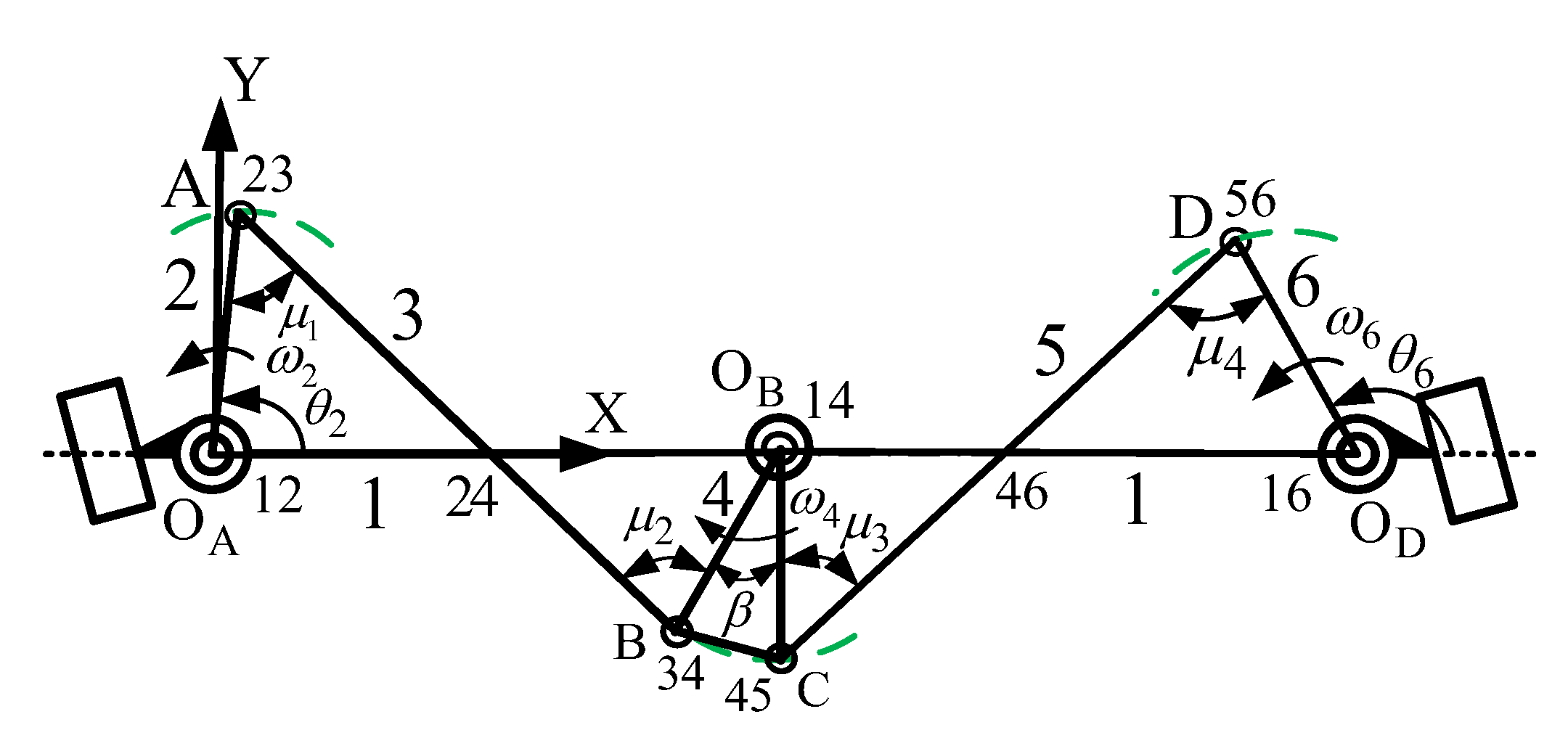
The mechanical advantage (MA) of a steering mechanism is defined as a measure of its transmission or maneuverability efficiency. Under ideal conditions—assuming no joint friction, no heat dissipation, and conservation of energy—the mechanical advantage of a Watt-I six-bar steering mechanism can be derived. Taking the Type II-1 steering mechanism as an example, when the input link is at the angular position θ2, the instantaneous centers (ICs) are those shown in Figure 10. The numerical notation ‘ij’ denotes the instantaneous center between links i and j. The positions of the joints—OA, A, B, OB, C, D, and OD—correspond to ICs 12, 23, 34, 14, 45, 56, and 16, respectively. For the first four-bar loop, the concept of equal velocity at the relative instantaneous center I24 is applied. By analyzing the corresponding triangle geometry and using the sine law, the mechanical advantage relationships can be established as follows:
MA 1 = T 4 T 2 = ω 2 ω 4 = ( I 14 I 24 ) ( I 12 I 24 ) = r 4 sin μ 2 r 2 sin μ 1
where T i and ω i ( i = 2 , 4 ) denote the applied torque and angular velocity of link i, respectively. The term I 14 I 24 represents the distance between the instantaneous centers of I 14 and I 24 I 24 , while I 12 I 24 denotes the distance between the instantaneous centers of I 12 aid I 24 . The Ackermann steering mechanism inherently satisfies the condition, r 4 = r 2 ; the MA of Ackermann steering mechanism, MAA, can be expressed as follows:
MA A = sin μ 2 sin μ 1
Similarly, the mechanical advantage for the second four-bar loop can be expressed as
MA 2 = T 6 T 4 = ω 4 ω 6 = ( I 16 I 46 ) ( I 14 I 46 ) = r 6 sin μ 4 r 4 sin μ 3
The overall MA of the Watt-I six-bar steering mechanism, MA W , can be derived as follows:
MA W = T 6 T 2 = ( T 6 T 4 )   ( T 4 T 2 ) = r 6 sin μ 4 sin μ 2 r 2 sin μ 3 sin μ 1
For any type of Watt-I six-bar steering mechanism composed of two identical four-bar linkages with equal-length steering arms, r 6 = r 2 , regardless of whether the link lengths r2 and r4 are equal; hence,
MA W = sin μ 4 sin μ 2 sin μ 3 sin μ 1
Equation (25) is suitable for all types of Watt-I six-bar steering mechanisms, emphasizing that transmission angles μ i ( i = 1 ~ 4 ) are the key factors influencing the mechanical advantage of the central-lever steering mechanism. In general, a higher MA value—whether for an Ackermann steering mechanism or a Watt-I six-bar steering mechanism—indicates greater steering maneuverability.

3. IPSO and DE-gr Optimization Methods

3.1. PSO and IPSO Algorithms

Particle Swarm Optimization (PSO) algorithm is a swarm intelligence algorithm proposed by Kennedy and Eberhart in 1995 [38], inspired by the social foraging behavior of birds and fish. In this algorithm, each particle represents an individual in a swarm. When searching for food, the movement of each individual is influenced by three main factors: inertial velocity, individual experience, and group influence. Inertial velocity represents the natural momentum of the particle, guiding its direction and speed. Individual experience reflects the particle’s tendency to return to its own best-known position, while group influence directs the particle toward the best-known position found by the swarm, typically corresponding to the individual currently closest to the optimal solution.
In the D-dimensional search space, each particle exhibits a position vector X i = ( x i 1 , x i 2 , , x i D ) with a velocity vector V i = ( v i 1 , v i 2 , , v i D ) . Particles are originally initialized in a uniform random manner through the search space, and the velocity is also randomly initialized. The new position ( X i t + 1 ) and new velocity ( V i t + 1 ) of each particle movement are as follows:
V i t + 1 = V i t + C 1 × r a n d ( ) × ( P i t X i t ) + C 2 × R a n d ( ) × ( P g t X i t )
X i t + 1 = X i t + V i t + 1 V max V i t V max
In the above equation, the term C 1 × r a n d ( ) × ( P i t X i t ) is referred to as the individual cognitive component, while C 2 × R a n d ( ) × ( P g t X i t ) represents the social cognitive component. The parameters C1 and C2, known as learning or acceleration coefficients, are typically positive constants. Here, i denotes the i-th particle, and t indicates the t-th iteration (generation). V i t and X i t represent the velocity and position of the i-th particle at iteration t, while V i t + 1   a n d   X i t + 1 are the corresponding values at iteration t + 1. P i t is the best-known position found by the i-th particle (personal best), and P g t is the best-known position found by the entire swarm (global best). The functions rand( ) and Rand( ) generate a random number uniformly distributed between 0 and 1. The drawback of original PSO is the requirement for specifying the velocity V i t within [−Vmax, Vmax].
In 1998, Shi and Eberhart [39] introduced a linear inertia weight factor ω(t) into the iterative process of PSO to enhance convergence performance. Later, in 2004, Ratnaweera et al. [40] proposed the concept of linearly varying the acceleration coefficients (C1, C2) during iterations, resulting in a modified Particle Swarm Optimization algorithm with mutation and time-varying acceleration coefficients (MPSO-TVAC). This method, also referred to as an improved version of PSO (IPSO), integrates both the linear inertia weight and time-varying acceleration coefficients, and will be applied in this study.
In the IPSO algorithm, the position X i t + 1 and velocity V i t + 1 of the i-th particle are updated according to the following equations:
V i t + 1 = ω   t × V i t + C 1   t × r a n d ( ) × ( P i t X i t ) + C 2   t × R a n d ( ) × ( P g t X i t ) X i t + 1 = X i t + V i t + 1
where
ω   t = ω min + ( N t ) N ( ω max ω min ) C 1   t = C 1 min + ( N t ) N ( C 1 max C 1 min ) C 2   t = C 2 max ( N t ) N ( C 2 max C 2 min )
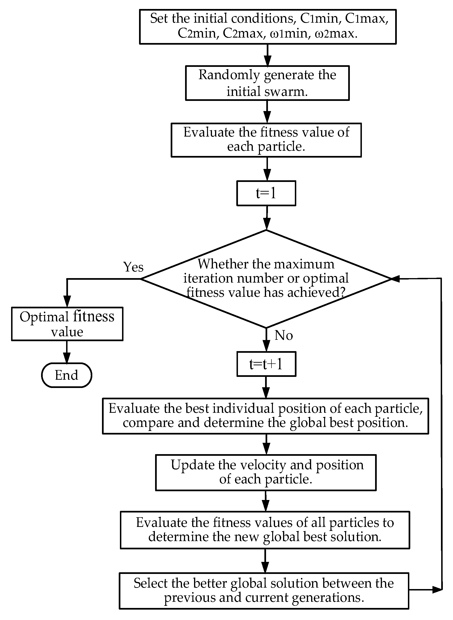
in which N represents the maximum number of iterations and t denotes the current iteration. ωmin and ωmax are the minimum and maximum values of the linear inertia weight, respectively. C1min and C1max are the minimum and maximum individual cognitive coefficients, while C2min and C2max refer to the minimum and maximum social cognitive coefficients of the swarm. A flow chart of the IPSO algorithm is shown in Figure 11.

3.2. Differential Evolution Algorithm

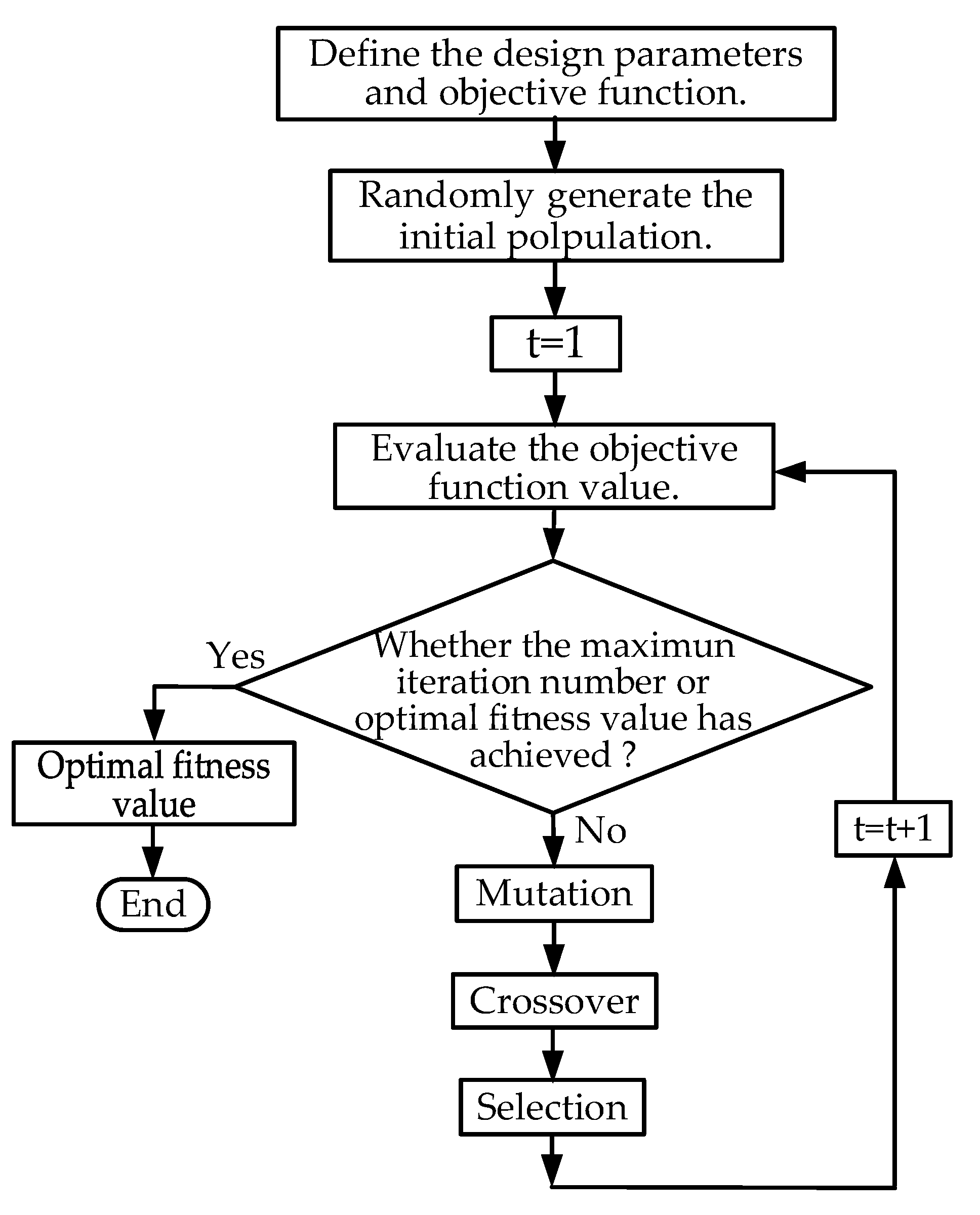
Storn and Price [41] proposed the Differential Evolution (DE) algorithm in 1997, a widely used metaheuristic for global optimization in a D-dimensional real-valued space. The standard DE algorithm consists of four key steps: initialization, mutation, crossover, and selection. After initialization, the remaining three steps are iteratively repeated throughout the optimization process.
(1)
Initialization
In a D-dimensional real-valued space, each vector—also referred to as a genome or chromosome—represents a candidate solution to the optimization problem. The i-th parameter vector in the population at iteration t is denoted as X r i t = [ x i , 1 t , x i , 2 t , . . . . . , x i , D t ] . At the initial iteration (t = 1), the population is generated using a uniform random distribution, ensuring broad coverage of the parameter space within the specified minimum and maximum bounds. X min = [ x min,1 , x min,2 , x min , D ] and X max = [ x max,1 , x max,2 , x max , D ] . Therefore, the j-th component of the i-th vector can be initialized as follows:
x i , j ( 1 ) = x min , j + r a n d i , j ( 0 , 1 ) ( x max , j x min , j )   ( i = 1 ,   2 ,     ,   N p ;   j = 1 ,   2 ,     ,   D )
where r a n d i , j ( 0,1 ) is a uniformly distributed random number in the interval [0, 1]. Np is the population size, i denotes the index of solution vector, and j denotes the index of the parameter in the vector.
(2)
Mutation
After initialization, for each target vector X r i t in the current iteration t, a corresponding mutant vector V i t , V i t = [ v i , 1 t , v i , 2 t , . . . . . , v i , D t ] , is generated through the mutation operation. The mutant vector is computed based on a predefined mutation strategy using other vectors selected from the current population, and is used to explore the solution space.
The five most commonly used mutation strategies are listed below:
  • DE/rand/1:
V i t = X r 1 t + F ( X r 2 t X r 3 t )
DE/best/1:
V i t = X b e s t t + F ( X r 1 t X r 2 t )
DE/rand/2:
V i t = X r 1 t + F ( X r 2 t X r 3 t ) + F ( X r 4 t X r 5 t )
DE/best/2:
V i t = X b e s t t + F ( X r 1 t X r 2 t ) + F ( X r 3 t X r 4 t )
DE/current-to-best/1:
V i t = X r i t + F ( X b e s t t X r i t ) + F ( X r 2 t X r 3 t )
The indices r1 ,  r2 ,  r3 ,  r4 ,   a n d  r5 are randomly generated within the range [1, Np] and r1 r2 r3 r4 r5 ri. X b e s t t represents the optimal individual vector with the optimal fitness function in the population at iteration t. ( X r 2 t X r 3 t ) is the difference vector. The mutation weighting factor (or mutation rate) F is a positive control parameter used to scale the difference vector in mutation operations. It typically takes a value in the range [0.4, 0.99], influencing the exploration capabilities of the algorithm.
(3)
Crossover
Through exponential crossover, the components of the mutant vector were combined with those of the target (parent) vector X r i t to form a trail (offspring) vector U i t , U i t = [ u i , 1 t , u i , 2 t , . . . . . , u i , D t ] .
u i , j t = v i , j t i f r a n d i , j ( 0 , 1 ) C R o r i = i r x i , j t o t h e r w i s e
where CR is a predefined control parameter known as the crossover rate, typically ranging within [0, 1]. r a n d i , j ( 0 , 1 ) denotes a uniformly distributed random number within the range [0, 1], which ensures that the trail vector U i t includes at least one component from the mutant vector V i t . i r is a randomly selected integer from the set {1, 2, …, D}, where D is the dimension of the problem.
(4)
Selection
The selection mechanism uses competitive selection to compare the objective values of the target and trial vectors, retaining the one with the better value for the next generation. The target vector of the next generation, X r i t + 1 , can be expressed as follows:
X r i t + 1 = U i t if   f ( U i t ) f ( X i t ) X r i t otherwise .
where f (.) is the objective function to be minimized.
The flow chart of the DE algorithm is shown in Figure 12. In this study, the values of the crossover rate and mutation factor are assigned based on the golden ratio (0.618:0.382), a technique referred to as the DE-gr method. The method has demonstrated efficient convergence and accurate optimal solutions in previous studies involving the optimal synthesis of steering mechanisms for three-axle, six-wheeled vehicles [34], four-bar path generation [35], and the spring-actuated cam-linkage composite mechanism in VCB applications [36].

4. Optimization Design of the Ackermann Steering Mechanisms

The steering mechanisms illustrated in Figure 3, Figure 4, Figure 5, Figure 6, Figure 7, Figure 8 and Figure 9 include the Ackermann steering mechanism as well as the Type I and Type II variants of Watt-I six-bar steering mechanisms for automobiles. The Ackermann steering principle, as defined in Equation (1), specifies a functional relationship between the input and output steering angles of the front wheels. This relationship must be accurately coordinated when addressing the optimal dimensional synthesis of steering mechanisms to ensure proper turning behavior. The objective function that must be minimized to optimize both the Ackermann and Watt-I six-bar steering mechanisms is identical. It consists of the mean of the sum of squared structural errors, along with a penalty function that accounts for constraint violations at selected steering positions, as defined in Equation (34).
Min     f ( X ) = i = 1 N [ δ o u t , i ( X ) δ i d e a l , i ( X ) ] 2 N + M h ( X )
The constraint inequality h ( X ) is as follows [37]:
(i)
For the Grashof mechanisms:
h ( X ) : r s + r l r p + r q
(ii)
For the Non-Grashof mechanisms:
h ( X ) : r s + r l > r p + r q
where r s , r l represent the shortest and longest link lengths, respectively, of the four-bar linkage, while r p , r q denote the lengths of the remaining two links.
In Equation (34), X denotes the design vector, N represents the number of selected steering angular positions, δ o u t , i denotes the output angle generated by the synthesized steering mechanism at i-th position, while δ i d e a l , i is the corresponding ideal output angle that satisfies the Ackermann condition. The steering error δ s , i , defined as δ s ,   i = δ o u t ,   i δ i d e a l ,   i   , represents the deviation between the synthesized and ideal output angle at the i-th steering position, is referred to as the structural error of the function generator. The term M h ( X ) is the penalty function applied when the design parameters violate the inequality constraints. The coefficient of M is set to 100,000. The function h(X) takes the value 1 when the constraint is violated and 0 otherwise. Equation (36) defines the constraint equation for the optimization of the Ackermann steering mechanism, which is inherently a Non-Grashof mechanism. In contrast, the Watt-I six-bar steering mechanism consists of two symmetric and identical four-bar linkages. Therefore, the constraint condition in this case is applied to the constituent four-bar linkage, which may be either a Grashof or Non-Grashof mechanism. As a result, depending on the design case, either the inequality constraint defined in Equation (35) or that in Equation (36) is applied.
In the following analysis of the optimal dimensional synthesis of both the Ackermann and Watt-I six-bar steering mechanisms, identical steering conditions and basic vehicle dimensions—referenced in [21]—were used for comparison. The wheel track W = 1480 mm and wheelbase L = 2960 mm were kept constant. The steering angle range for the front inner wheel was set as −30° δ i n 40 ° . Design points were selected at one-degree intervals across this range, resulting in a total of N = 71 selected steering positions. The parameters used for the two employed metaheuristic optimization methods, DE-gr and IPSO, are summarized in Table 2. For a fair comparison of convergence efficiency and precision between the two employed algorithms, the population size (Np) was initially set to the same value (Np = 10). If the algorithms failed to converge to a feasible optimal solution within the maximum iterations, then increasing the population size to 20 enabled successful convergence. The DE-gr algorithm can employ either the DE/best/1 or DE/best/2 mutation strategies. Each optimization algorithm was executed for 100 or 200 iterations per run, and each numerical experiment was repeated 100 times to ensure statistical reliability of the results.
For the optimal design of the Ackermann steering mechanism, there are only two design parameters, which can be represented as the design vector X = [ x 1 , x 2 ] T = [ r 2 , θ 20 ] T . The allowable ranges for these design parameters are 100 r 2 1000 ( mm ) , 30 θ 2 o 90 ( ° ) and r 3 0.96 r 1 . The design must also satisfy the inequality constraint defined in Equation (36).
The prescribed number of iterations and numerical experiments for each applied optimization method were fully executed in a single run of the optimal synthesis program, which was implemented in MATLAB. From each run, the best solution, i.e., the one yielding the minimum fitness value—was selected. However, achieving a minimum fitness value does not guarantee a global optimum or the best minimum structural error. Therefore, the entire optimization process was repeated ten times, producing ten candidate solutions. Among these, the solution with the lowest maximum structural error (Min-Max error) was chosen as the final optimal solution. A similar procedure was followed for the optimal dimensional synthesis of the Watt-I six-bar steering mechanisms.
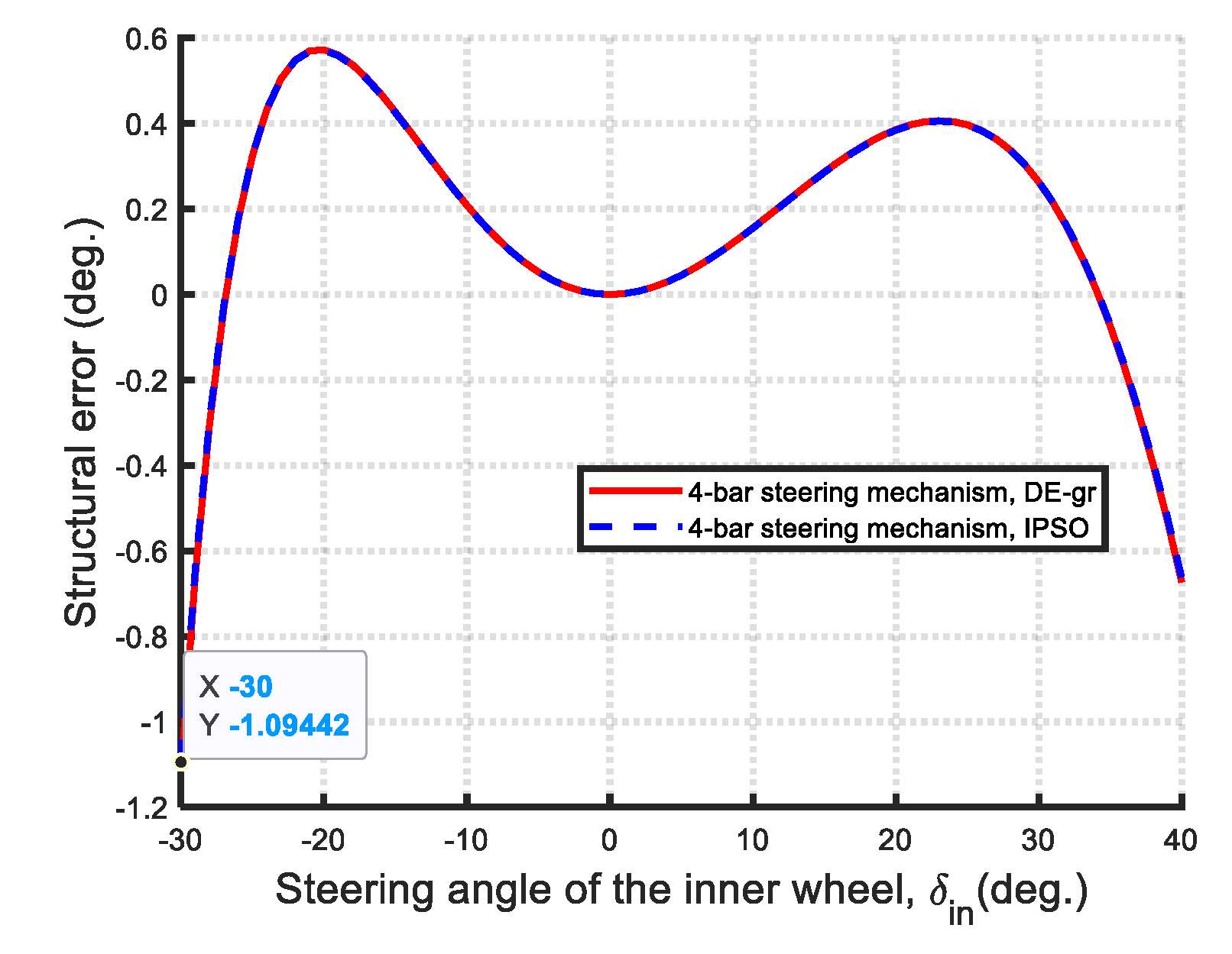
Table 3 presents the optimal results of the dimensional synthesis of the Ackermann steering mechanism using the two metaheuristic algorithms. In the table, the unit of link length is given in millimeters (mm), while the units for angular positions and maximum structural error are given in degrees (°). The Min-Max structural error achieved by the IPSO method is 1.0944°, which is slightly better than the 1.1160° obtained by the DE-gr method. For the optimal design of the Ackermann steering mechanism, both the DE-gr and IPSO methods use a population size of 10. Both methods were run with 200 iterations and 100 experimental trials.
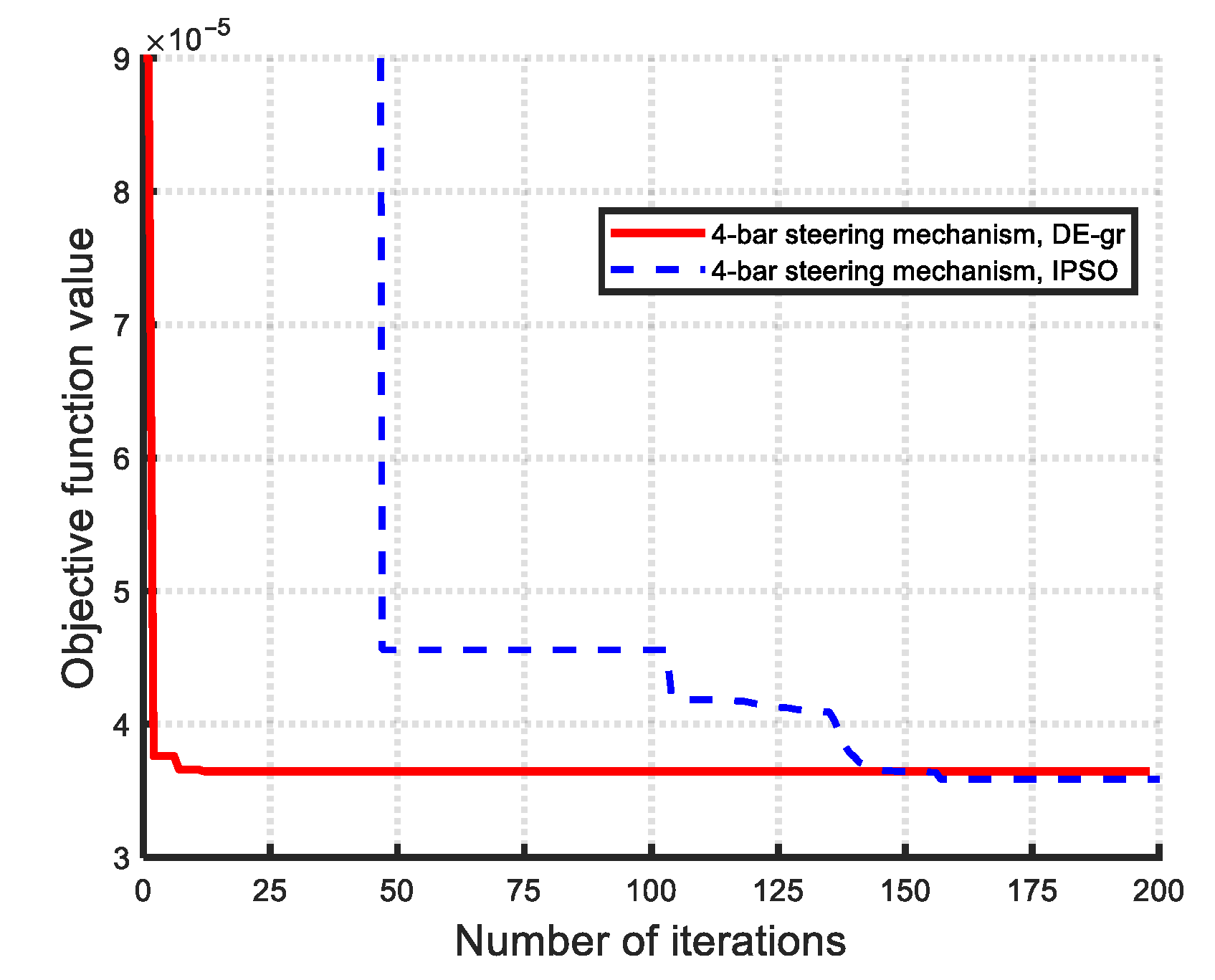
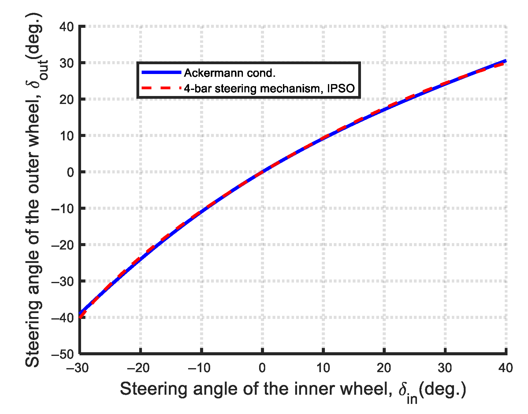
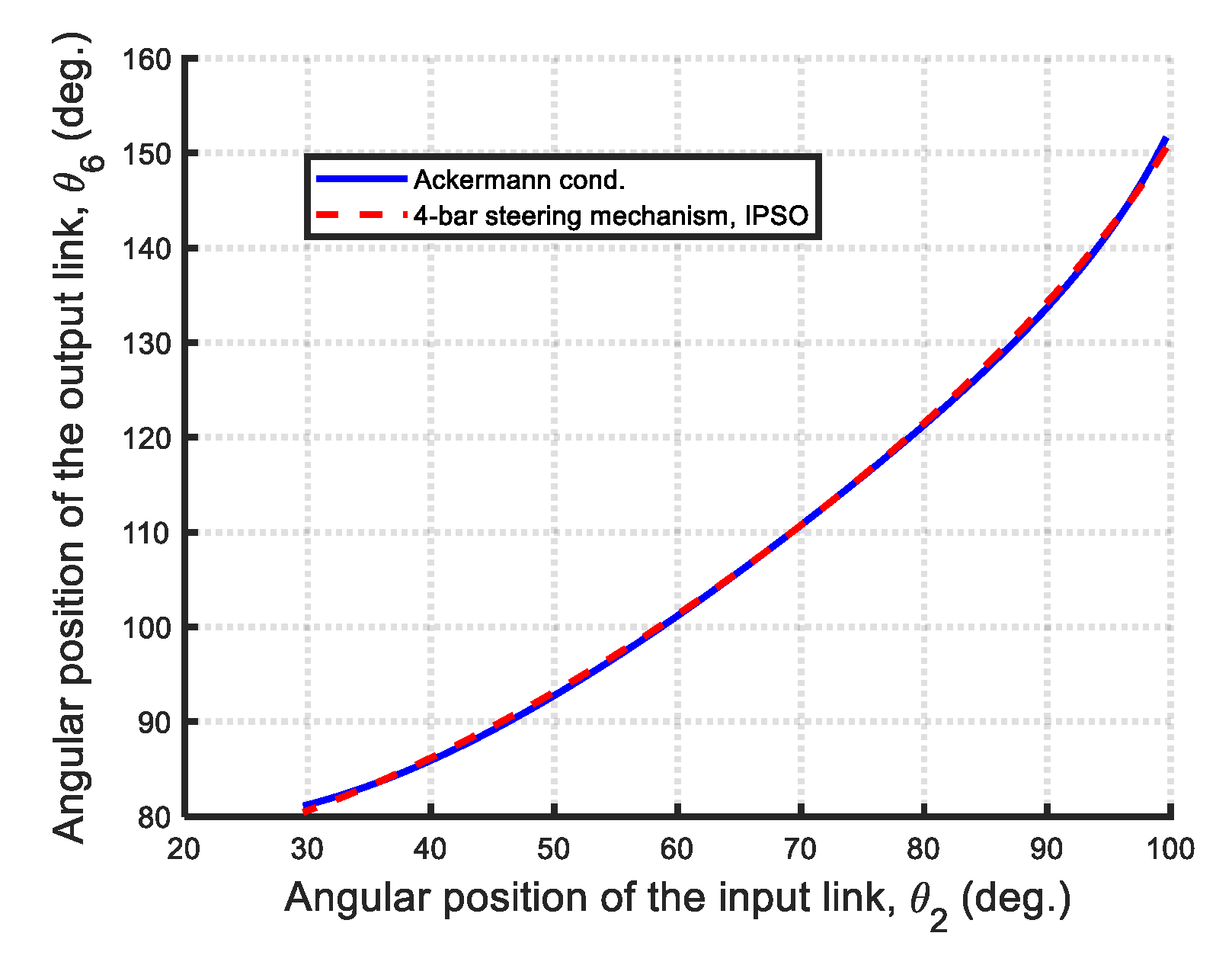
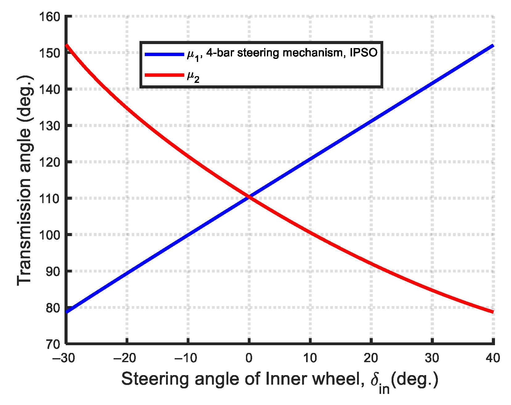
Figure 13 illustrates the convergence curves of both optimization methods. The DE-gr algorithm reaches its optimal solution in approximately 10 iterations, indicating a faster convergence rate compared to the IPSO method, which converges at around 155 iterations. Figure 14 displays the structural error curves of the optimal Ackermann steering mechanisms obtained using the DE-gr and IPSO algorithms. As shown, there is no significant difference between the two results. The structural error curve illustrates the deviation between the output steering angle ( δ o u t ) produced by the optimized mechanism and the ideal output angle ( δ i d e a l ) that satisfies the Ackermann steering condition. The error distribution clearly exhibits end-divergence behavior: near the extremes of the steering range, the error reaches a maximum of approximately 1.09°, whereas within the central 90%, ( 27 ° δ i n 36 ° ) , of the steering stroke—the range most relevant to typical driving conditions—the maximum error remains below 0.6°. These results demonstrate improved steering accuracy compared to previous studies [8,13], although they remain inferior to those reported in [2]. The kinematic performance of the optimal Ackermann steering mechanism obtained via the IPSO method was further analyzed using a MATLAB-based kinematic analysis program. For visualization and dynamic validation, a kinematic simulation was also conducted using the multi-body dynamics software ADAMS v2015. Figure 15 shows the relationship between the front outer and inner wheel steering angles compared to the ideal Ackermann condition. Figure 16 presents the generated and ideal output angles of the optimized mechanism. Figure 17 displays the transmission angle curve, which deviates from the ideal 90° but remains around 45°, within the [25°, 40°] range. Figure 18 shows the mechanical advantage (MA) curve, with a maximum of 2.0917 and a minimum of 0.47559, reflecting the variable efficiency of torque transmission across the steering stroke. Figure 19 illustrates the kinematic simulation of the optimal Ackermann steering mechanism using ADAMS v2015.

5. Optimal Design of the Watt-I Six-Bar Steering Mechanisms

5.1. Optimal Synthesis Results of the Type I Watt-I Six-Bar Steering Mechanisms

The optimal synthesis of Type I Watt-I six-bar steering mechanisms can be categorized into six distinct cases, classified as follows: (1) Type I-1 (refer to Figure 4), ( h 0 , β 0 ) : this type includes two sub-cases based on whether the lengths of link 2 and link 4 are equal or not—(a) Type I-1A ( r 4 = r 2 ) , a configuration with five design variables and (b) Type I-1B ( r 4 r 2 ) , a configuration with six design variables. (2) Type I-2 (refer to Figure 5) ( r 4 r 2 ) ( h 0 , β = 0 , θ 40 = π / 2 ) : A single configuration is used, without sub-categorization. (3) Type I-3 (refer to Figure 6) ( h = 0 , β 0 ) : This type encompasses three sub-cases—(a) Type I-3A ( r 4 = r 2 ) , a configuration with four design variables; (b) Type I-3B ( r 4 r 2 ) , a configuration with five design variables; (c) Type I-3C ( r 4 = r 2 , θ 3 o = θ 5 o = 0 ° ) , a configuration with two design variables. For the optimal dimensional synthesis of the Type I Watt-I six-bar steering mechanisms, the objective function and design constraints are defined in Equations (34)–(36). The design information—including the geometric relationships, design vector, parameter ranges, and properties of the constituent four-bar linkage—varies by case and is summarized in Table 4. Note that the last column of Table 4 indicates whether the first constituent four-bar linkage of the optimal Type I Watt-I six-bar steering mechanism obtained from Table 5 is a Grashof or Non-Grashof mechanism, based on the dimensions of the obtained optimal designs (similar usage in Table 6 for the Type II Watt-I six-bar mechanisms). The first constituent four-bar linkages in Type I-1A, Type I-3A, and Type I-3C feature equal-length steering links ( r 4 = r 2 ) , classifying them as Non-Grashof mechanisms—with similar characteristics to that of the Ackermann steering mechanism. Therefore, they can be referred to as Ackermann-like Watt-I six-bar steering mechanisms. In contrast, the first four-bar linkages in Type I-1B, Type I-2, and Type I-3B have unequal-length steering links ( r 4 r 2 ). Depending on whether the inequality constraint in Equation (36) or (37) is applied and successfully yields an optimal solution, these linkages may be classified as either Grashof mechanism (such as Type I-2) or Non-Grashof mechanisms (such as Type I-1B and Type I-3B). The use of unequal-length steering links distinguishes these from Ackermann mechanisms, classifying them as Non-Ackermann-like Watt-I six-bar steering mechanisms.
(1)
Optimal synthesis results of the Type I-1
The Type I-1 Watt-I six-bar steering mechanism is divided into two cases based on the number of design variables: Type I-1A (five variables) and Type I-1B (six variables). For the optimal synthesis of the Type I-1 Watt-I six-bar steering mechanism, the DE-gr method uses a population size of 10, while the IPSO method uses 20. Both methods are run with 200 iterations and 100 experimental trials. Table 5 summarizes the optimal results for all cases of Type I Watt-I six-bar steering mechanisms using the DE-gr and IPSO methods. Related figures are presented in the next section.
(A)
Type I-1A: ( h 0 , β 0 , r 4 = r 2 )
The optimal results for the Type I-1A are presented in rows 1–4 of Table 5. The DE-gr method achieves a smaller Min-Max steering error (0.4233) compared to IPSO (0.4690). Figure 20 shows the convergence curves, where DE-gr converges faster (at the 65th iteration) than IPSO (at the 90th iteration). Figure 21 compares the structural error curves of the optimal mechanisms from both algorithms. Figure 22, Figure 23, Figure 24, Figure 25 and Figure 26 present the kinematic analysis results of the optimal Type I-1A Watt-I six-bar steering mechanism obtained using the DE-gr method. Figure 22 shows the relationship between the front outer and inner wheel steering angles. Figure 23 compares the actual and ideal output angles. Figure 24 displays the transmission angle curve, with all deviations from 90° being within 45°, indicating high transmission efficiency. Figure 25 shows the mechanical advantage (MA) curve, with MAmax = 2.0917 and MAmin = 0.47559. Figure 26 illustrates the kinematic simulation performed in ADAMS v2015, validating both the steering performance and practical feasibility of the synthesized mechanism.
(B)
Type I-1B: ( h 0 , β 0 , r 4 r 2 )
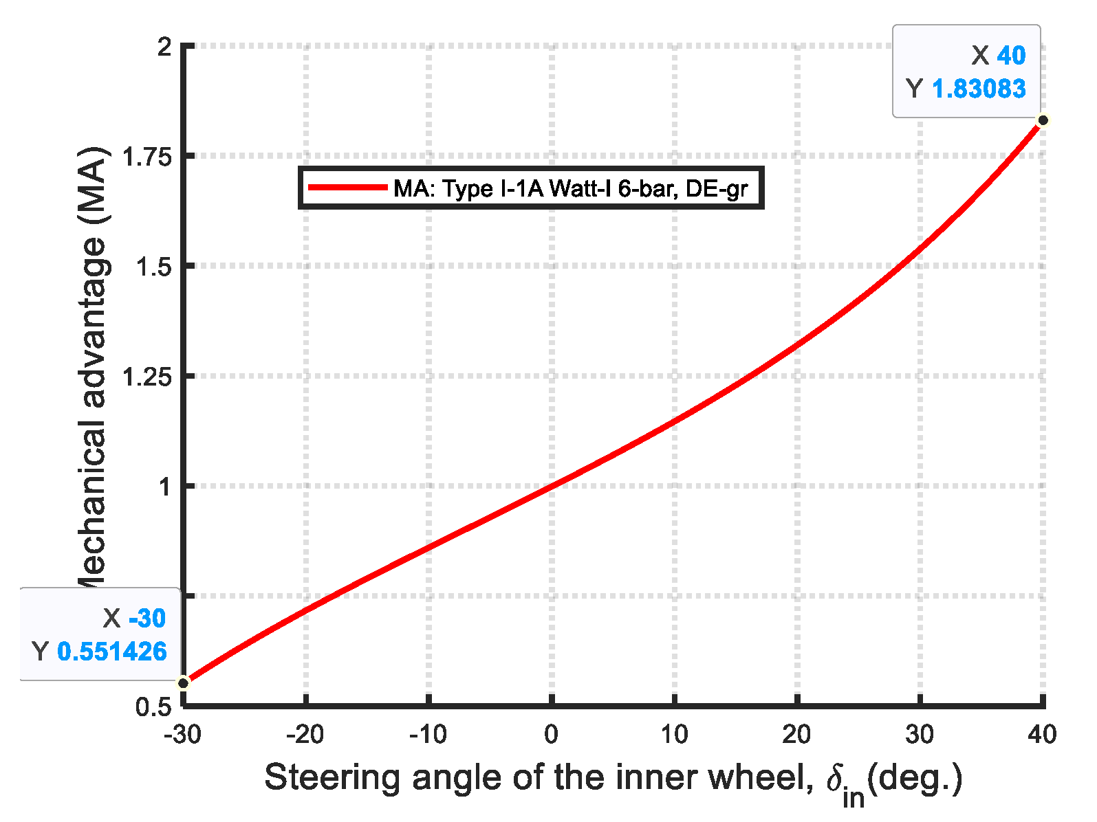
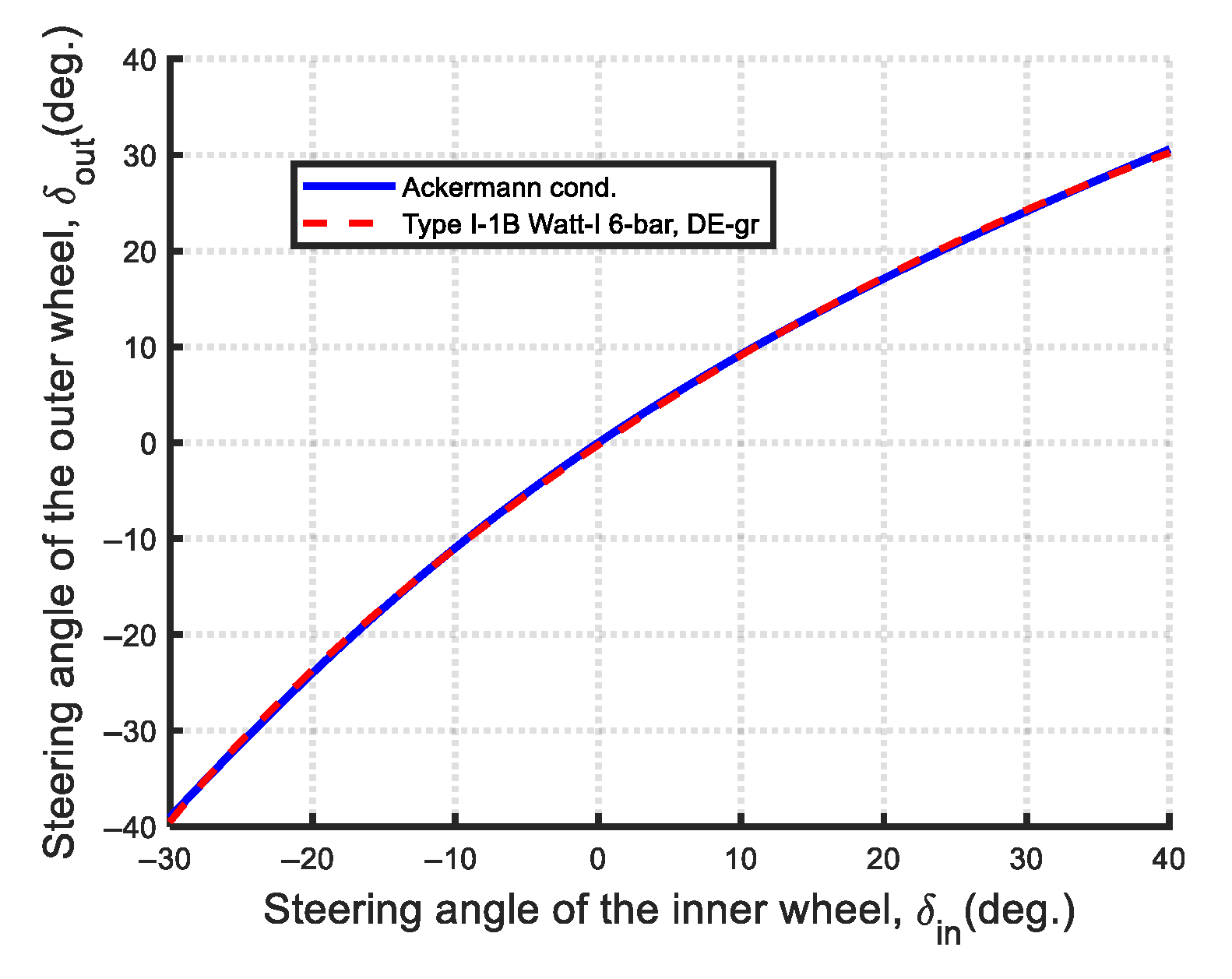
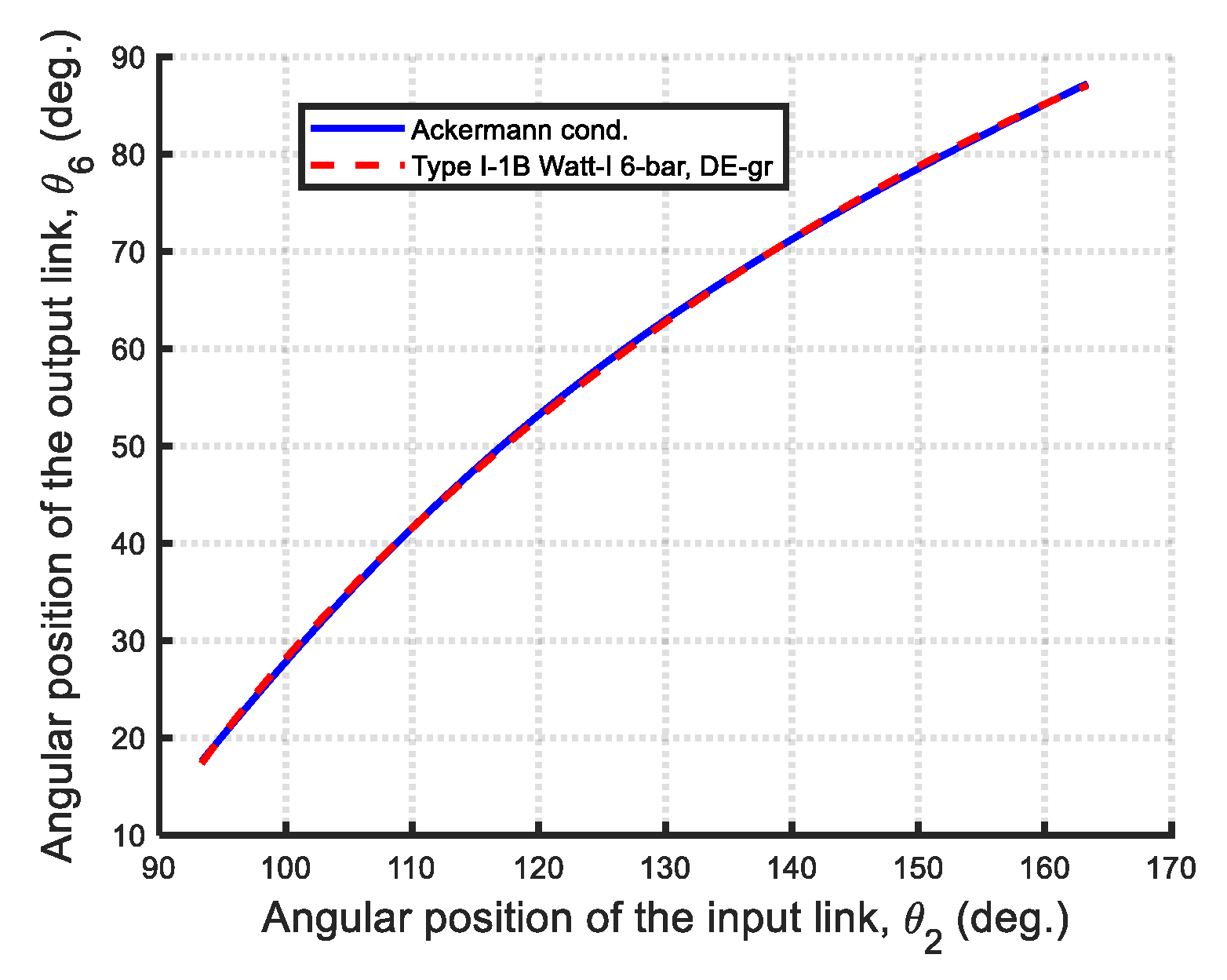
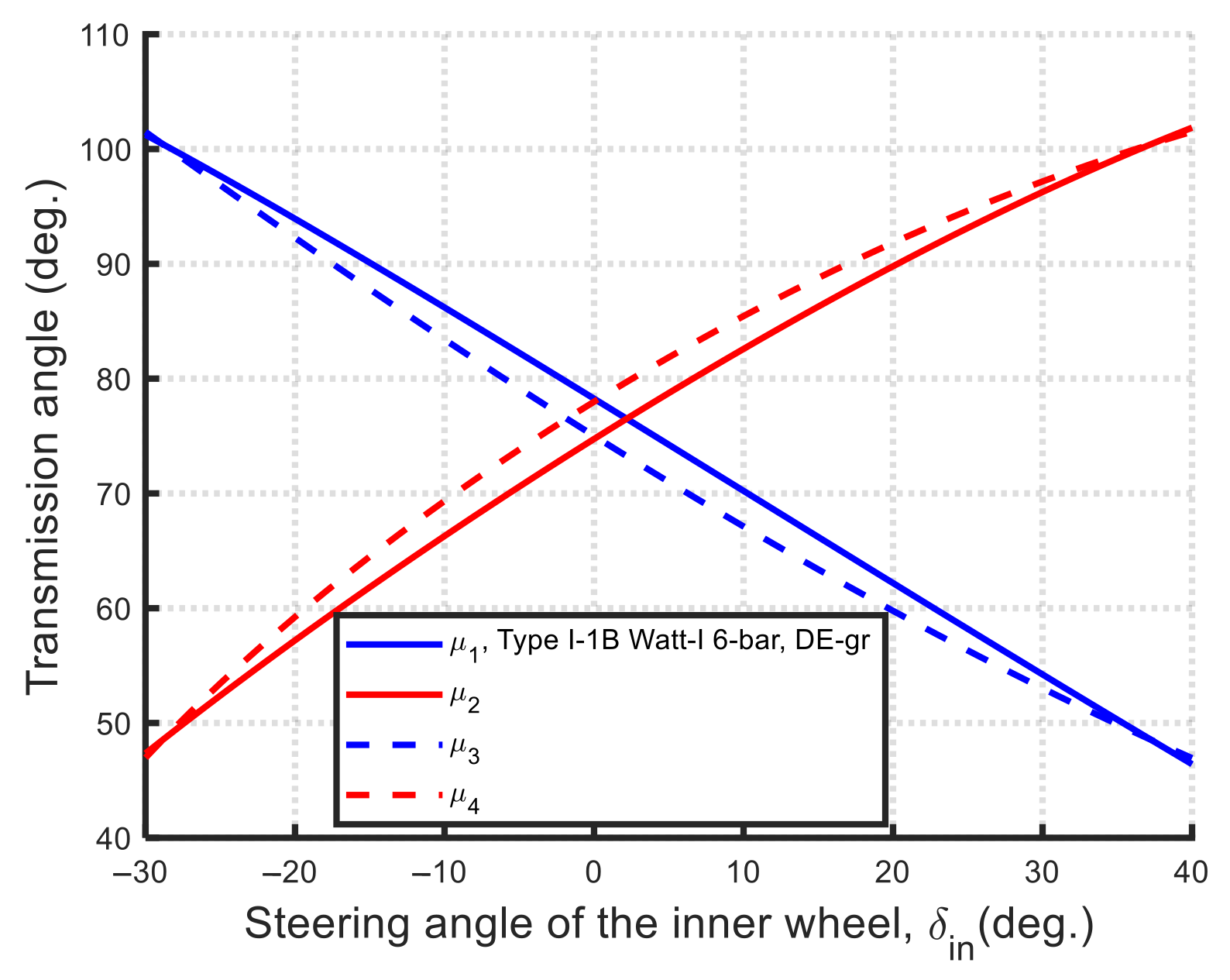
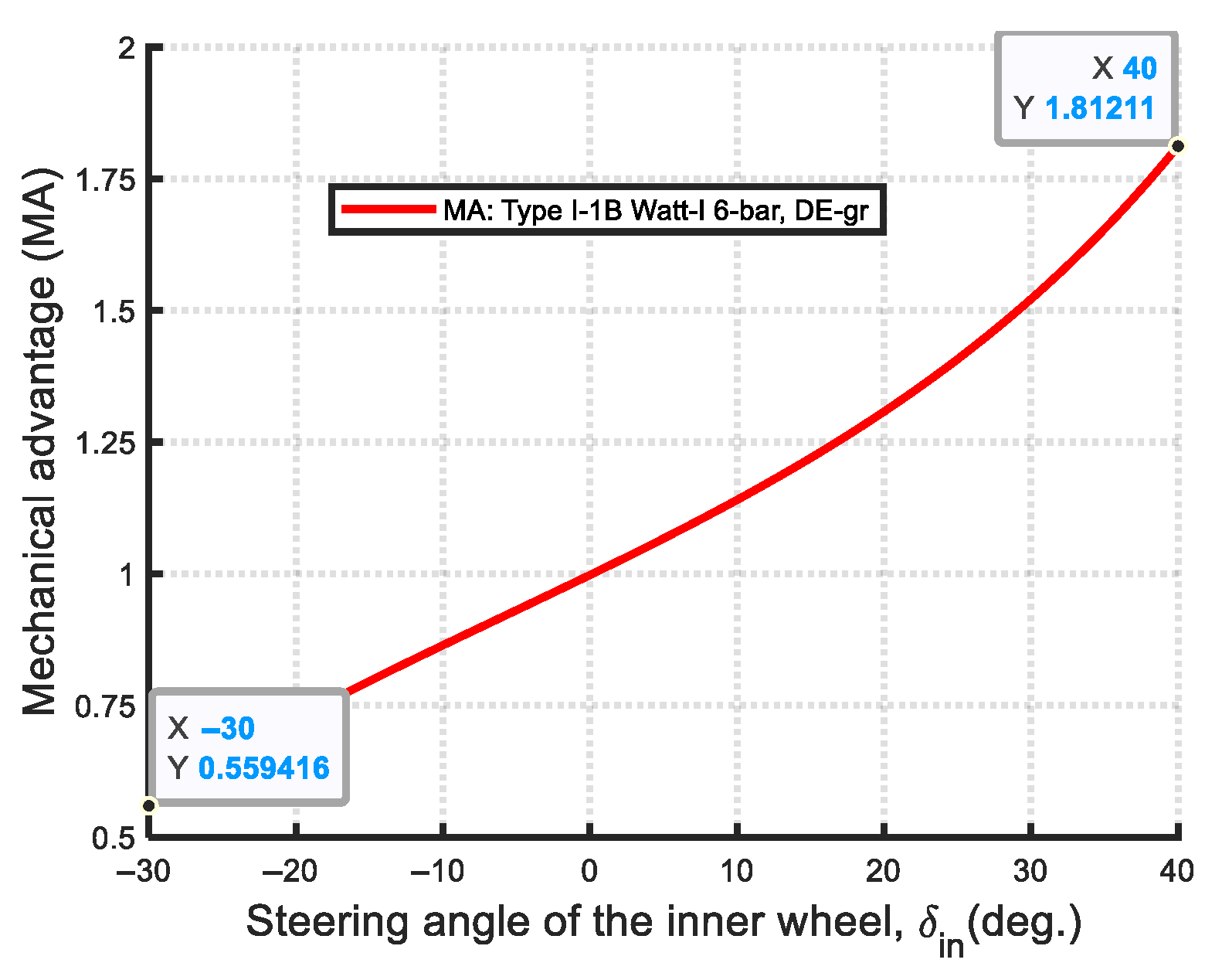
The optimal results for the Type I-1B are presented in rows 5–8 of Table 5. The DE-gr method achieves a lower Min-Max error (0.3544) compared to IPSO (0.4898), indicating superior optimization performance. Both methods demonstrate high synthesis accuracy and outperform those reported in previous studies [25]. Figure 27 shows the convergence curves, with DE-gr reaching the optimal solution at the 38th iteration, significantly faster than IPSO, which reaches the optimal solution at the 95th iteration. Figure 28 compares the structural error curves of the optimal mechanisms from both algorithms. Figure 29 and Figure 30 show the kinematic analysis results of the DE-gr optimized Type I-1B Watt-I six-bar steering mechanism. Figure 29 illustrates the relationship between the front outer and inner wheel steering angles. Figure 30 compares the actual and ideal output angles. Figure 31 shows the transmission angle curve, with all deviations from 90° within 45°, indicating high transmission efficiency. Figure 32 presents the mechanical advantage (MA) curve with MAmax = 1.81211 and MAmin = 0.55942. Figure 33 displays the kinematic simulation conducted in ADAMS v2015, validating both the steering performance and practical feasibility of the synthesized mechanism.
Due to space limitations, some figures, such as the steering angle relationships between the front outer and inner wheels, convergence curves, mechanical advantage curves, and transmission angle curves, are omitted in the following optimal synthesis cases of the Type I Watt-I six-bar steering mechanism.
(2)
Optimal synthesis results of Type I-2
  • Type I-2: ( h 0 , β = 0 , r 4 r 2 , θ 40 = π / 2 )
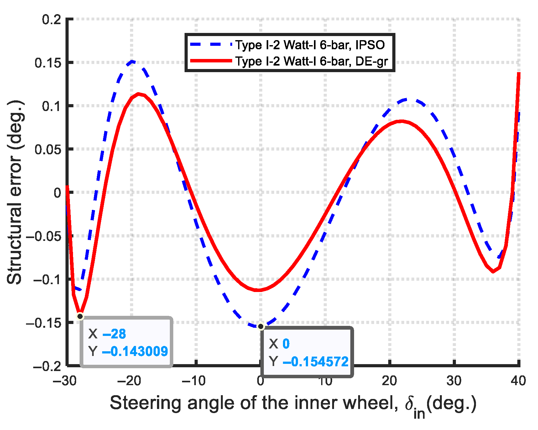
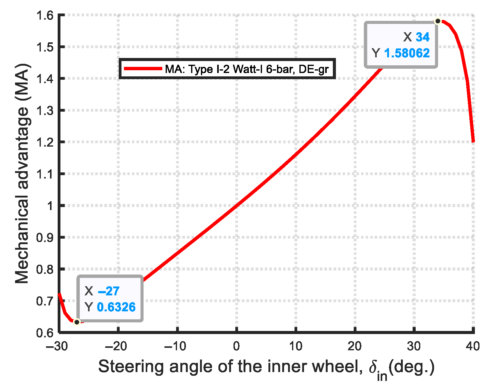
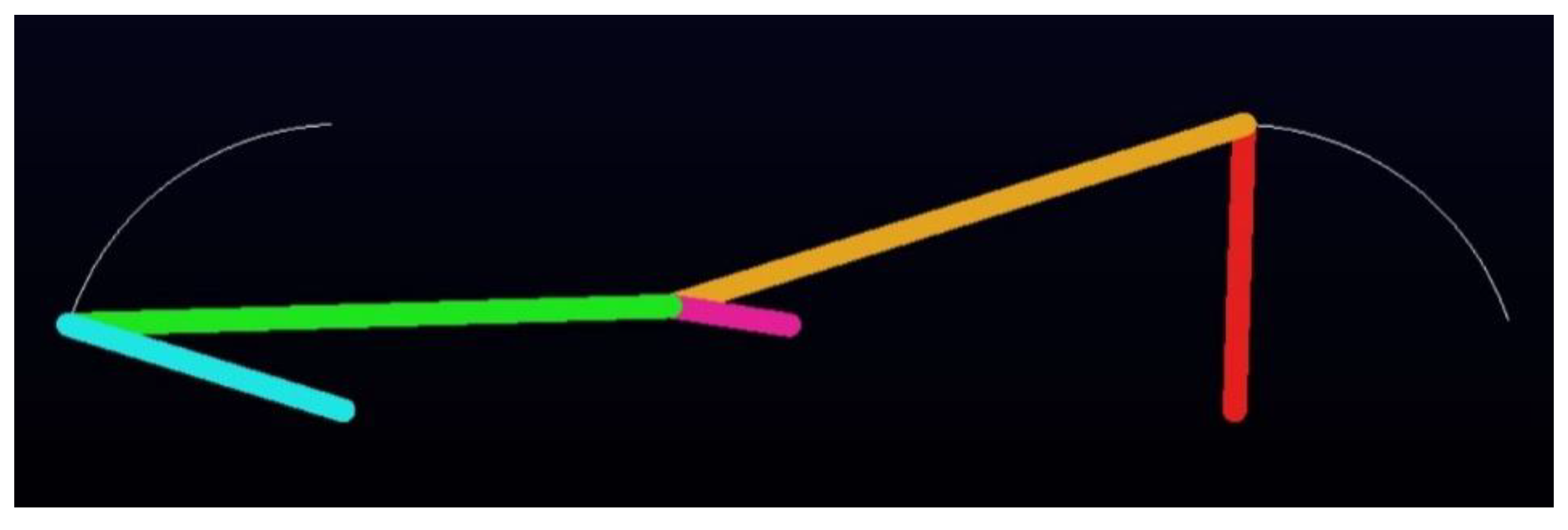
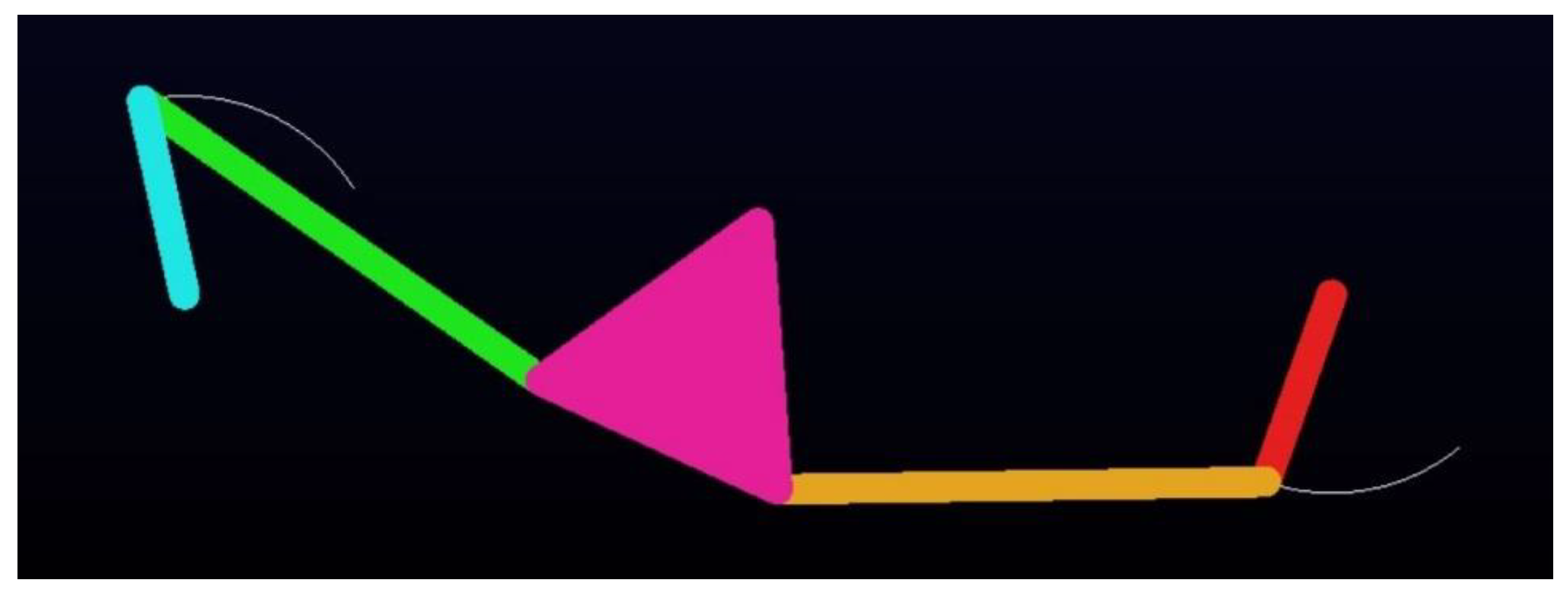
For the optimal synthesis of the Type I-2 Watt-I six-bar steering mechanism, both DE-gr and IPSO methods use a population size of 20, with 200 iterations and 100 experimental trials. The optimal results for the Type I-2 are presented in rows 9–12 of Table 5. The DE-gr method achieves a lower Min-Max error of 0.1431 compared to the 0.1546 obtained by the IPSO method, indicating superior optimization performance. Both methods demonstrate high synthesis accuracy and outperform those reported in previous studies [18,22,23]. Figure 34 compares the structural error curves of the optimal mechanisms from both algorithms. Figure 35 and Figure 36 present the kinematic analysis results of the DE-gr optimized Type I-2 Watt-I six-bar steering mechanism. Figure 35 shows the mechanical advantage (MA) curve, with MAmax = 1.5841 and MAmin = 0.6312. Figure 36 displays the kinematic simulation of the optimal Type I-2 Watt-I six-bar steering mechanism using ADAMS v2015. The supplementary video of kinematic simulation can be downloaded in Supplementary File. The first constituent four-bar linkage of this optimal steering mechanism, characterized by unequal-length steering links ( r 4 r 2 ) , is a Grashof mechanism. This configuration is classified as a Non-Ackermann-like Watt-I six-bar steering mechanism and, to the best of our knowledge, is presented for the first time in the literature.
(3)
Optimal synthesis results of Type I-3
  • Type I-3: ( h = 0 , β 0 )
The Type I-3 Watt-I six-bar steering mechanism is divided into three cases based on the number of design variables: Type I-3A (four variables), Type I-3B (five variables), and Type I-3C (two variables). For all three cases, both DE-gr and IPSO methods use a population size of 10. The number of iterations is 200 for Type I-3A and I-3B, and 100 for Type I-3C. Each case includes 100 experimental trials.
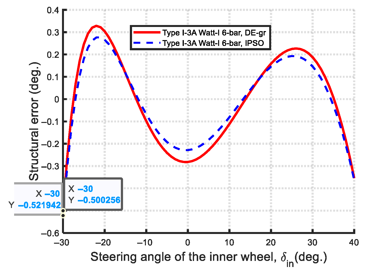
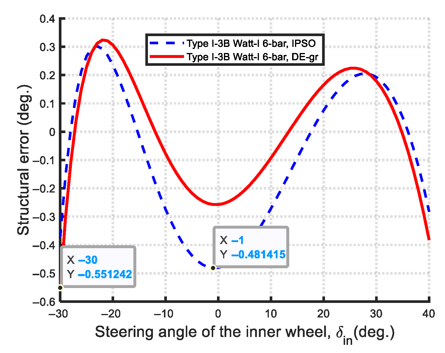
The optimal results for the Type I-3A and Type I-3B Watt-I six-bar steering mechanism are presented in rows 13–16 and 17–20 of Table 5, respectively. For the optimal Type I-3A mechanism, the DE-gr method achieved a lower Min-Max error (0.5002) compared to IPSO (0.5219). Figure 37 compares the structural error curves of both methods. For the optimal Type I-3B mechanism, the IPSO method achieved a lower Min-Max error (0.4814) than the DE-gr method (0.5512). Figure 38 compares the structural error curves of both methods. Figure 39 and Figure 40 show the kinematic simulations of the optimal Type I-3A and Type I-3B Watt-I six-bar steering mechanisms, optimized by the DE-gr and IPSO methods, respectively, which were performed using ADAMS v2015 to validate both the steering performance and practical feasibility of the synthesized mechanism.
  • Type I-3C: ( h = 0 , β 0 , r 4 = r 2 )
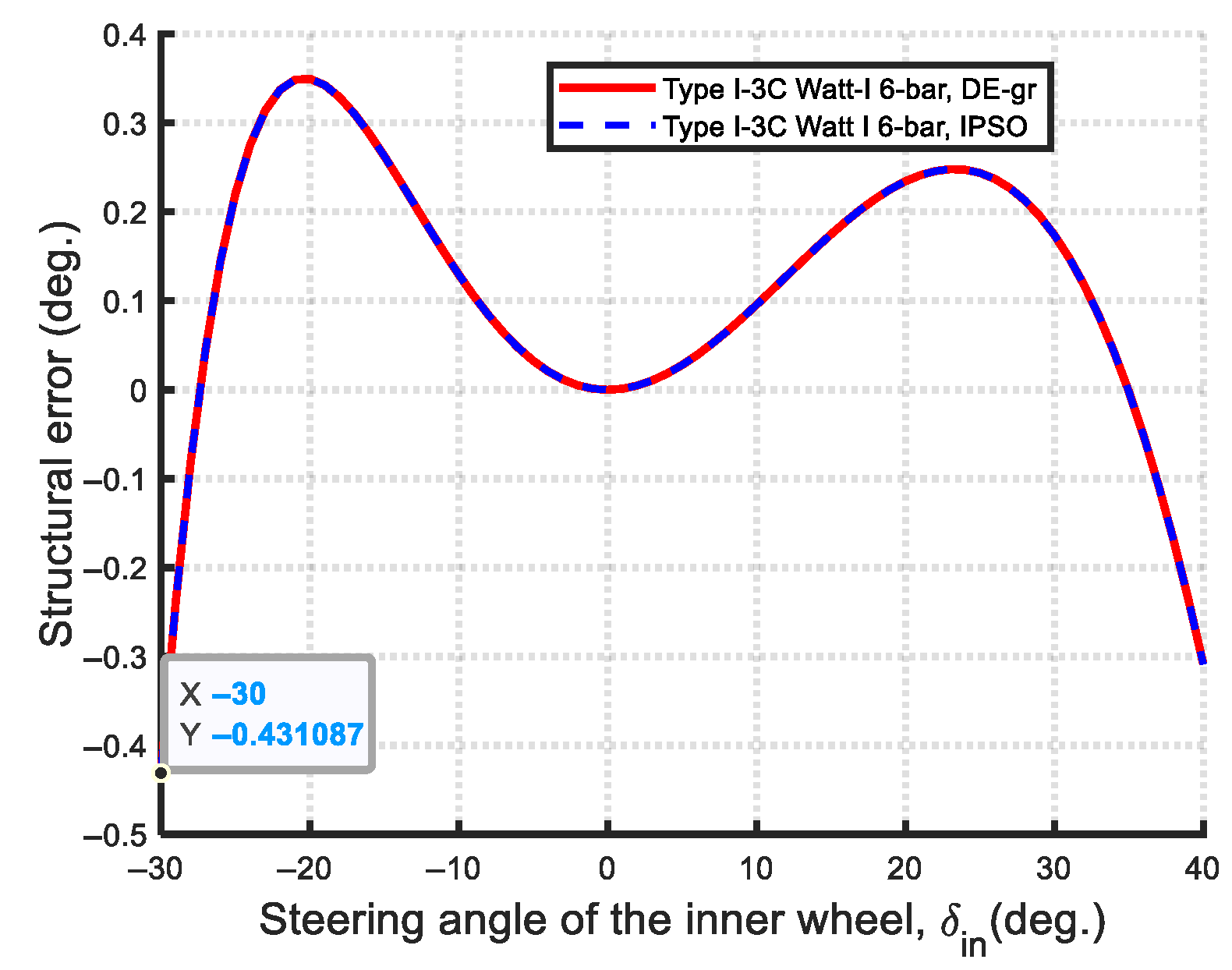
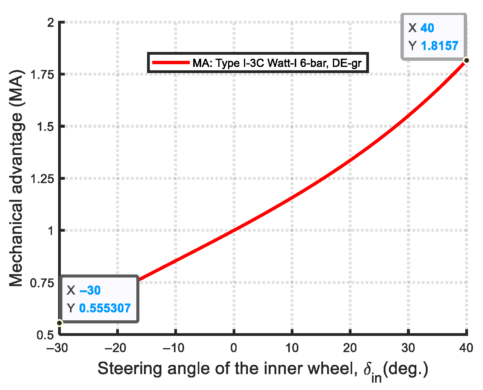
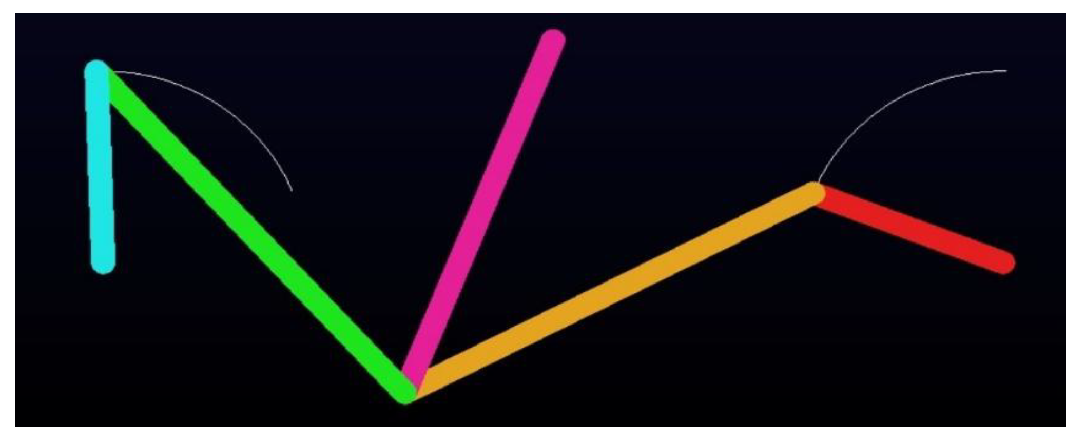
Type I-3C is a special case of the Type I-3A mechanism, where links 3 and 5 are initially parallel to the fixed link, θ 3 o = θ 5 o = 0 ° , and the design parameters only two, r 2 and θ 2 o . The optimal results for the Type I-3C Watt-I six-bar steering mechanism are presented in rows 21–24 of Table 5. Both the DE-gr and IPSO methods always converge to identical optimal solutions. Figure 41 shows that the optimal solution achieves a Min-Max error of 0.4311, which is significantly lower than the Ackermann mechanism’s error of 1.0944 and those reported in previous study [21]. Figure 42 and Figure 43 present the kinematic analysis of the DE-gr optimized mechanism, including the mechanical advantage curve (MAmax = 1.8157, MAmin = 0.55531) and the ADAMS v2015 simulation. Type I-3C can be regarded as two identical Ackermann steering mechanisms connected in series. With more suitable link lengths, this symmetric configuration offers superior steering accuracy compared to a single Ackermann mechanism. The supplementary video of kinematic simulation can be downloaded in Supplementary File.

5.2. Optimal Synthesis Results of the Type II Watt-I Six-Bar Steering Mechanism

The optimal synthesis of Type II Watt-I six-bar steering mechanisms encompasses five distinct cases, classified as follows: (1) Type II-1 (refer to Figure 7) ( h 0 , β 0 ) : This configuration includes two sub-cases based on whether the lengths of link 2 and link 4 are equal or not—Type II-1A ( r 4 = r 2 ) , a configuration with five design variables, and Type II-1B ( r 4 r 2 ) , a configuration with six design variables. (2) Type II-2 (refer to Figure 8) ( h 0 , β = 0 , θ 40 = π / 2 ) : A single configuration without sub-categorization. (3) Type II-3 (refer to Figure 9) ( h = 0 , β 0 ) : This configuration includes two sub-cases—Type II-3A ( r 4 = r 2 ) , a configuration with four design variables, and Type II-3B ( r 4 r 2 ) , a configuration with five design variables. To optimize the Type II Watt-I six-bar steering mechanisms, the objective function and constraints follow Equations (34)–(36). Each case has distinct basic geometric relations, a design vector, parameter ranges, and properties of the first constituent four-bar linkage, as summarized in Table 6. In this Table, the meaning of Ackermann-like or Non-Ackermann-like is same as in Table 5.
(1)
Optimal synthesis results of Type II-1
There were two cases of the Type II-1 Watt-I six-bar steering mechanism, shown in Figure 8, namely Type II-1A ( r 4 = r 2 ) and Type II-1B ( r 4 r 2 ) , which involved five and six design parameters, respectively. For the optimal synthesis of Type II-1A and Type II-1B Watt-I six-bar steering mechanisms, DE-gr and IPSO use a population size of 10 and 20, respectively. Both methods were run for 100 iterations and 100 experimental trials. Table 7 summarizes the optimal results for all cases of Type II Watt-I six-bar steering mechanisms using the DE-gr and IPSO methods.
(A)
Type II-1A: ( h 0 , β 0 , r 4 = r 2 )
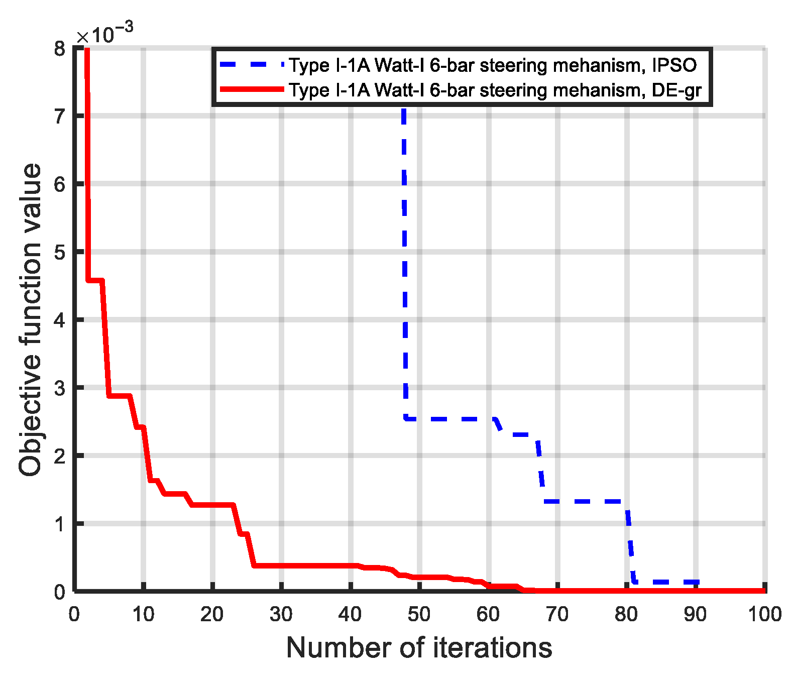
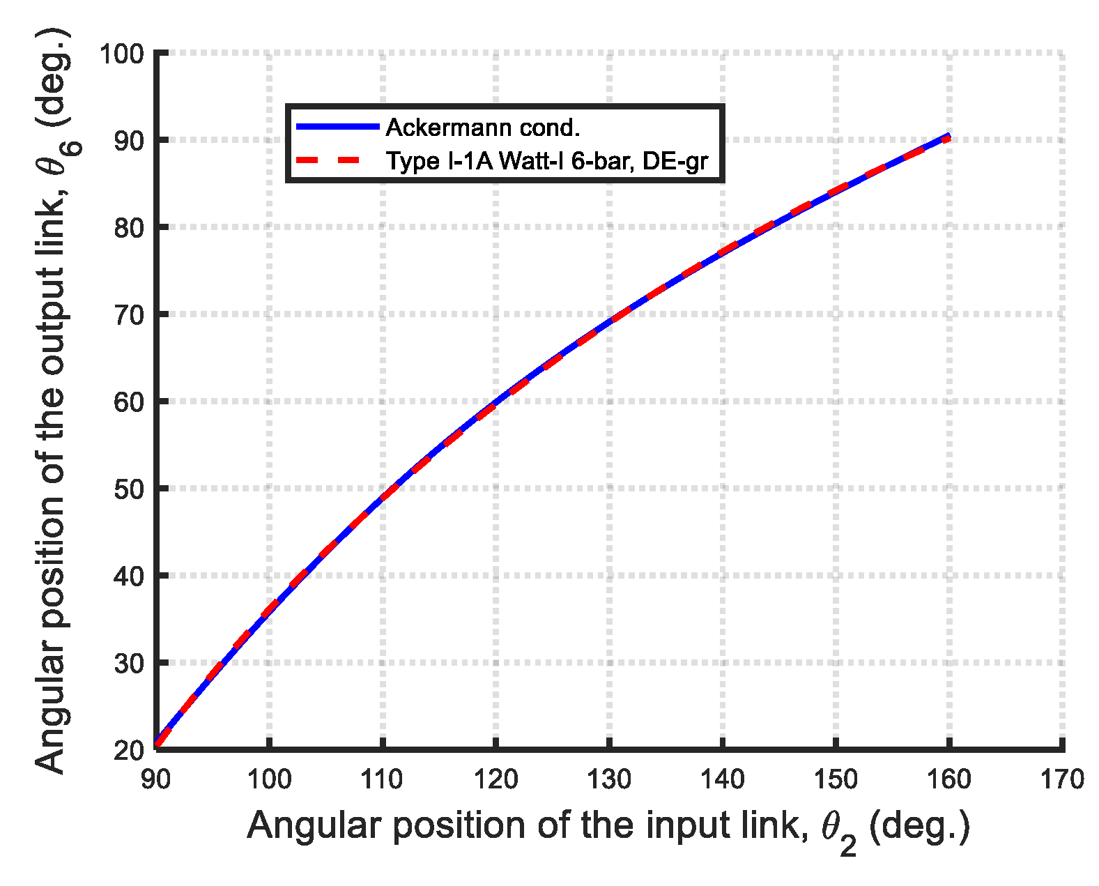
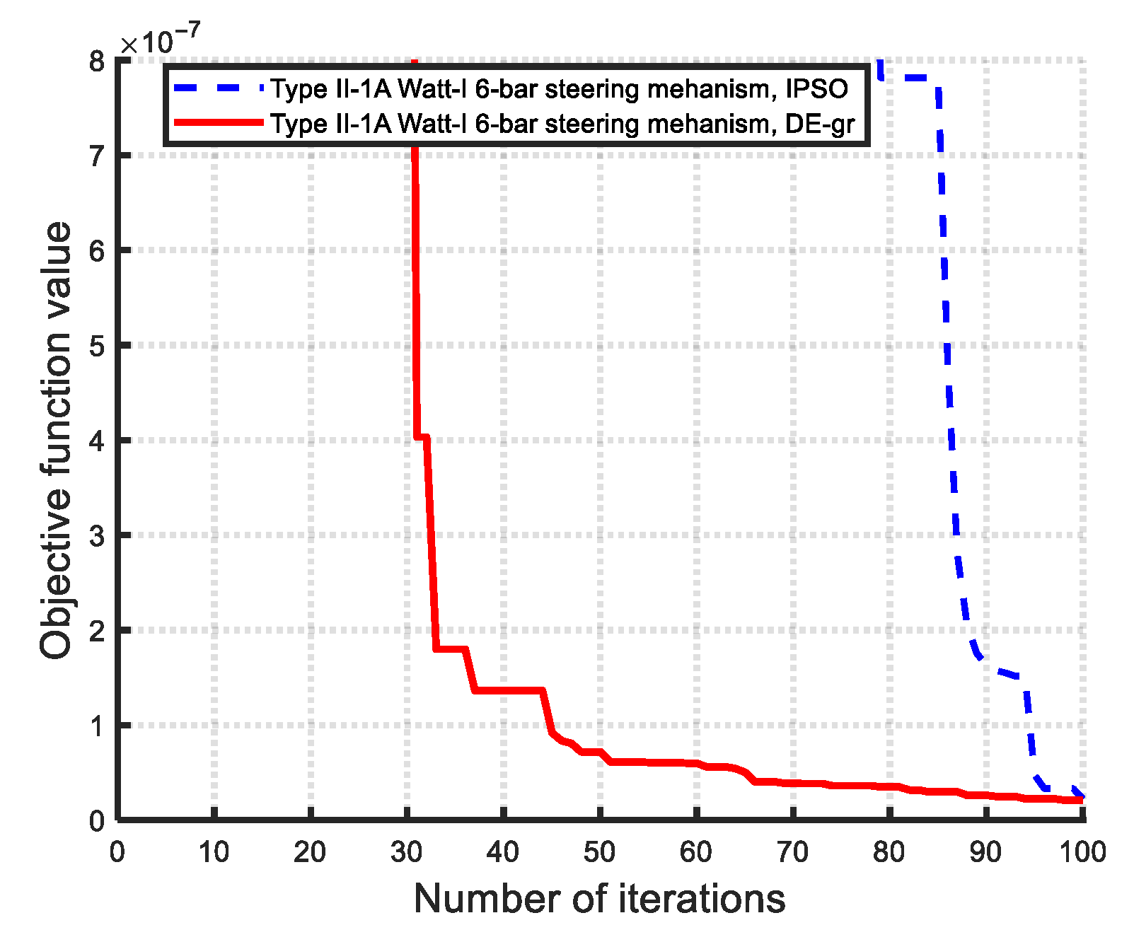
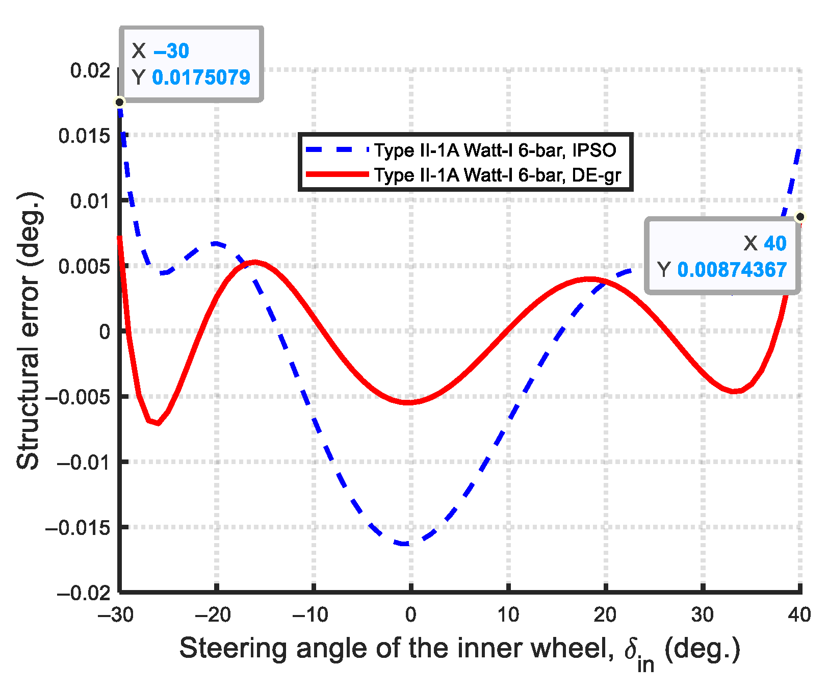
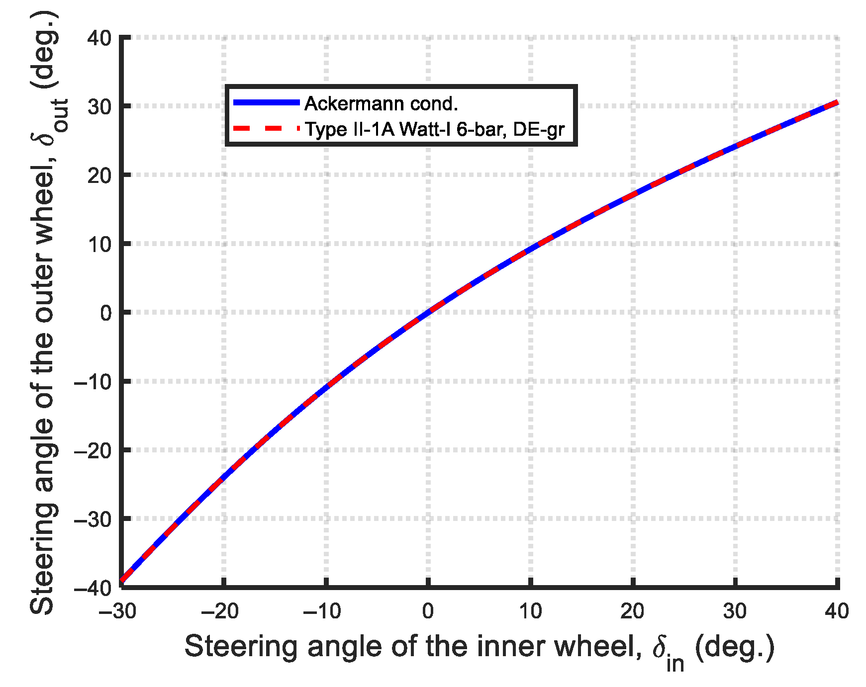
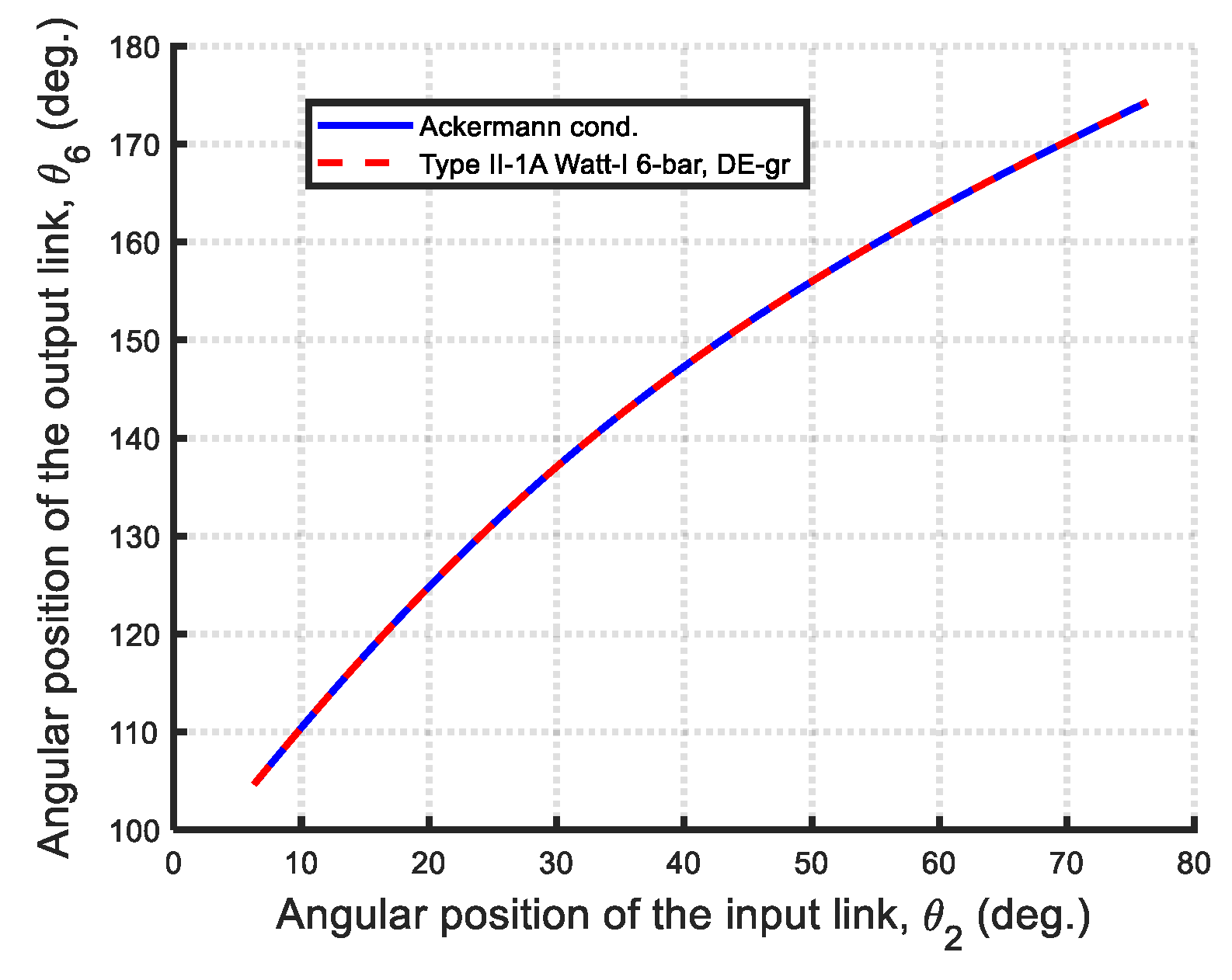
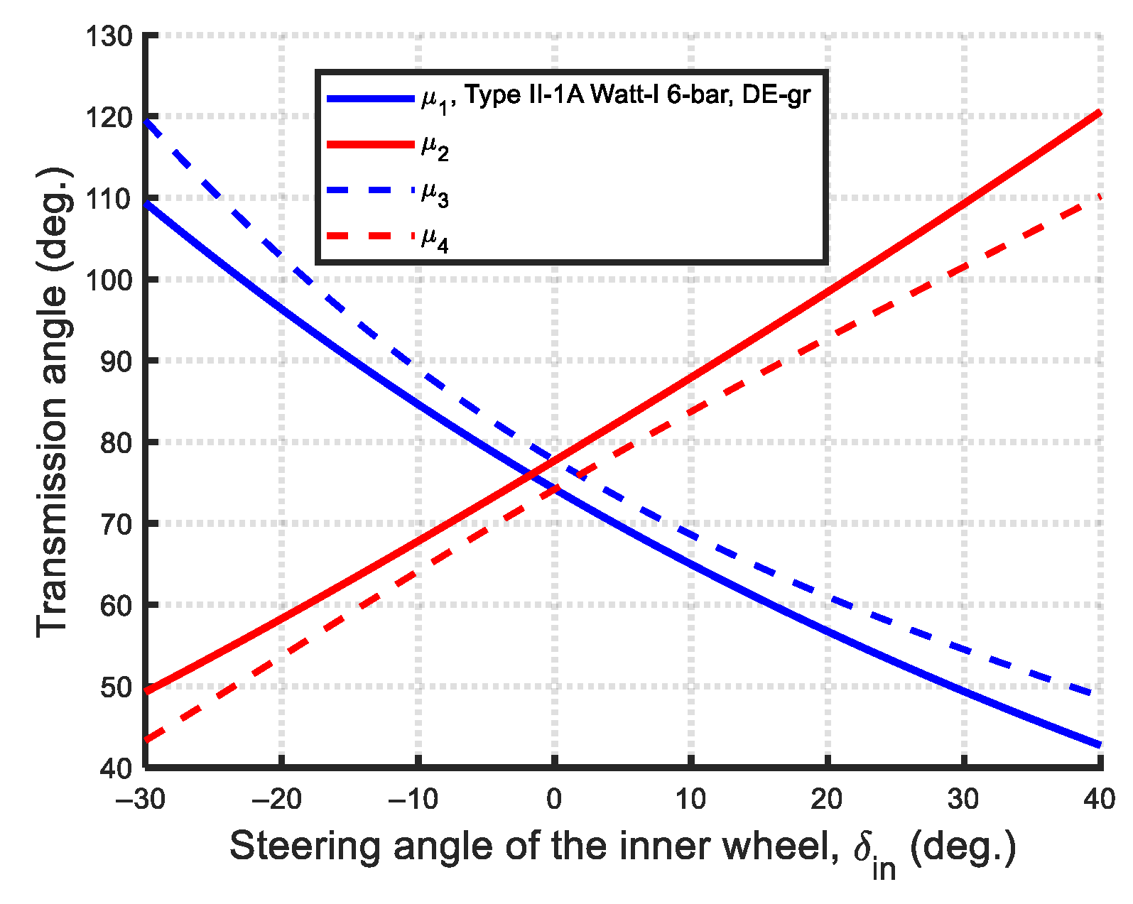
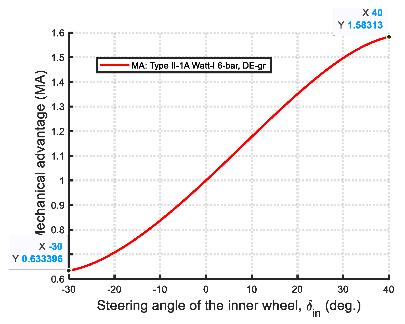
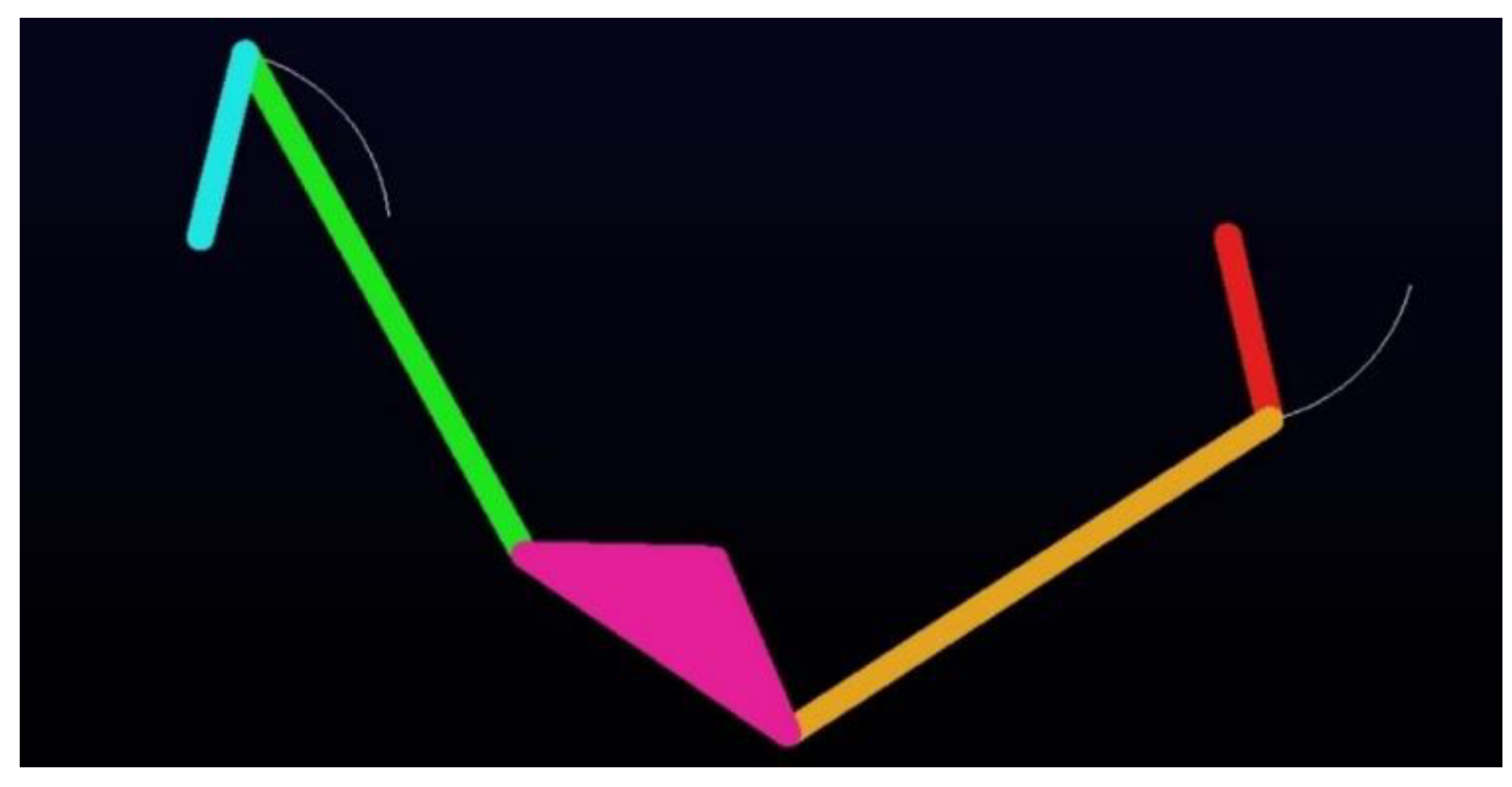
The optimal results for the Type II-1A Watt-I six-bar steering mechanism, obtained using the DE-gr and IPSO methods, are listed in rows 1–4 of Table 7. The DE-gr method achieves a lower Min-Max error of 0.0087, compared to the 0.0175 obtained by the IPSO method, indicating superior optimization performance. Both methods exhibit high synthesis accuracy and outperform those reported in previous study [27]. The convergence behavior of both methods is illustrated in Figure 44, which shows that the DE-gr method converges at the 98th iteration, making it slightly faster than IPSO method, which converges at the 100th iteration. This demonstrates that the DE-gr has a more accurate and faster convergence. Figure 45 compares the structural error curves of the optimal steering mechanisms obtained from two algorithms. Figure 46, Figure 47, Figure 48 and Figure 49 show the kinematic analysis of the optimal Type II-1A steering mechanism, derived using the DE-gr method. Figure 46 compares the actual generated angles with the ideal steering output angles. Figure 47 further illustrates the actual generated and ideal output angles of the optimized mechanism, confirming their close adherence to the desired kinematic behavior. Figure 48 shows the transmission angle curves, where all within ±45° of the ideal, indicating acceptable transmission performance. Figure 49 presents the mechanical advantage (MA) curve, with MAmax = 1.58313 and MAmin = 0.633396. Finally, Figure 50 illustrates the kinematic simulation of the optimal Type II-1A Watt-I six-bar steering mechanism performed using ADAMS v2015, validating both the steering performance and practical feasibility of the synthesized mechanism.
(B)
Type II-1B: ( h 0 , β 0 , r 4 r 2 )
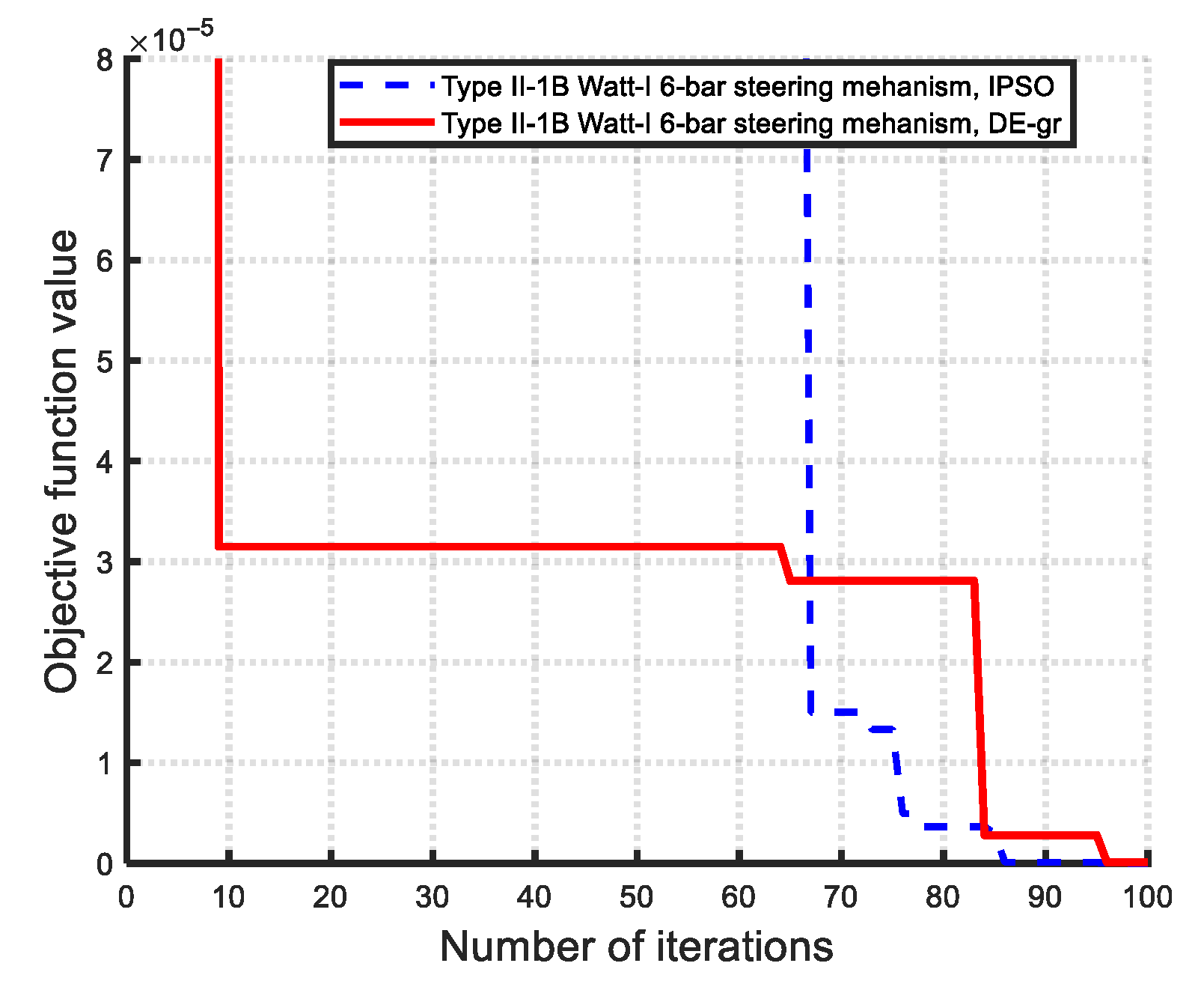
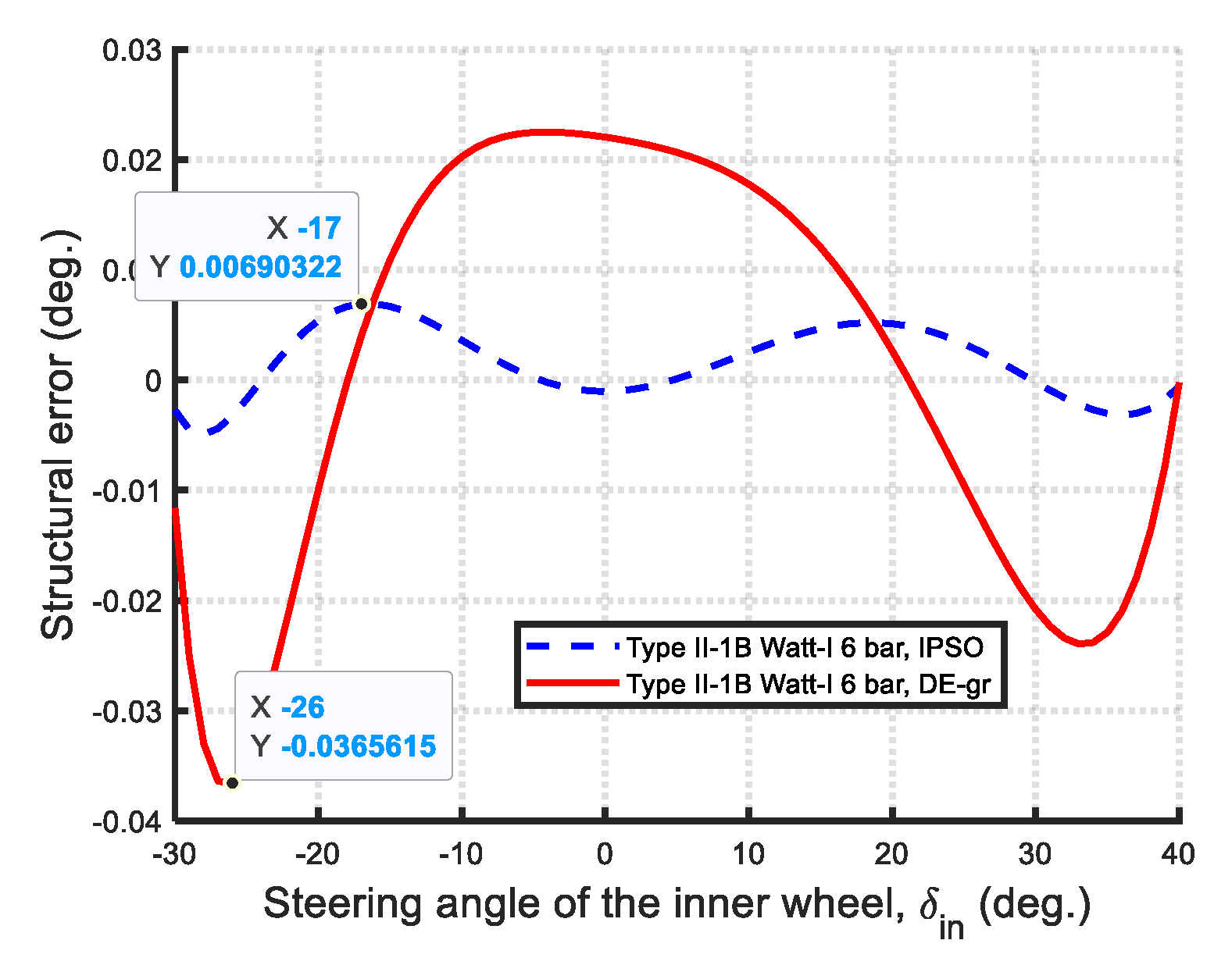
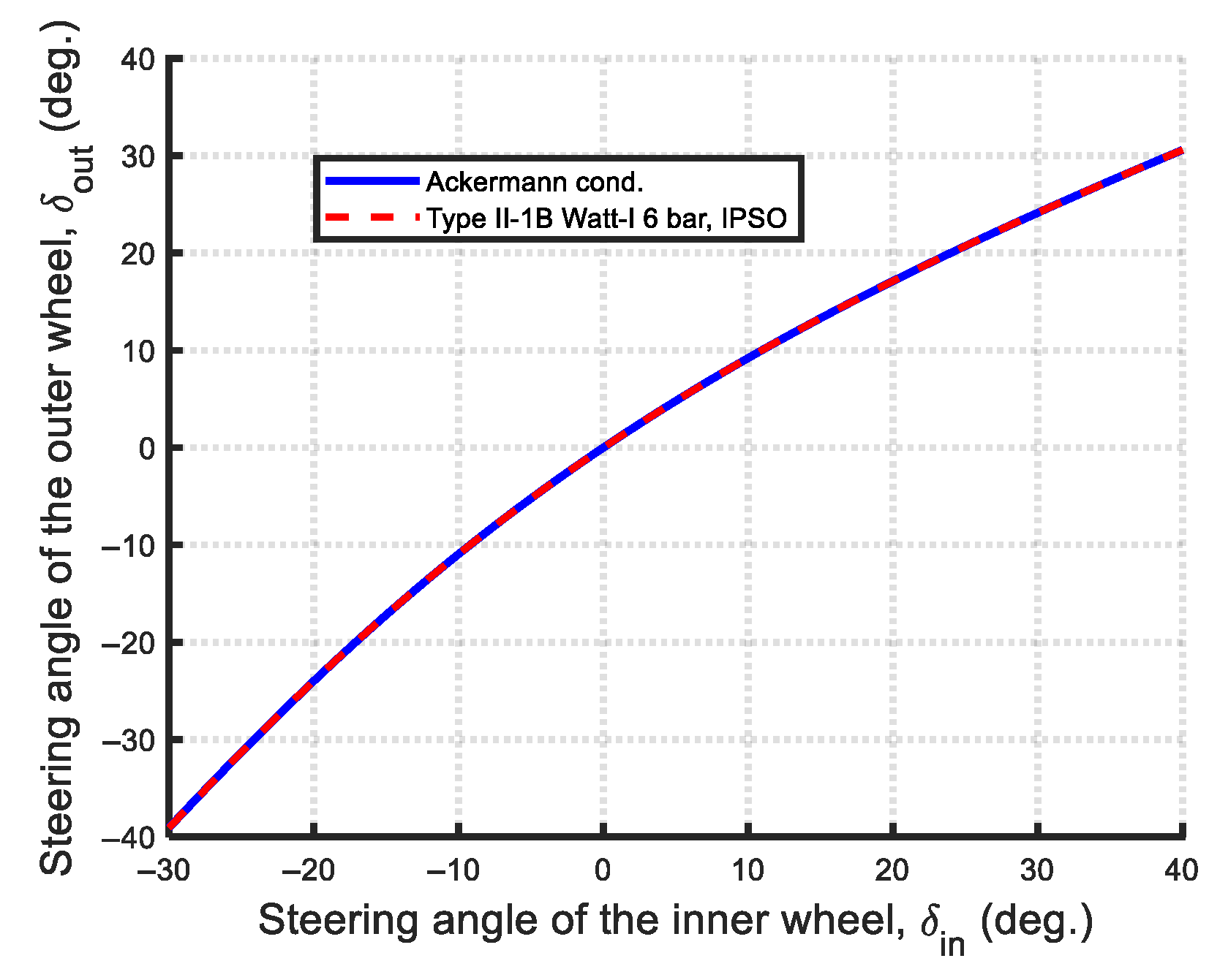
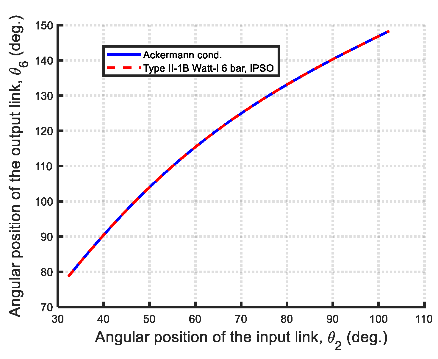
The optimal results for the Type II-1B Watt-I six-bar steering mechanism, obtained using the DE-gr and IPSO methods, are presented in rows 5–8 of Table 7. The results show that the IPSO method achieves a lower Min-Max error of 0.0069, significantly better than the 0.0366 error obtained by the DE-gr method, indicating superior accuracy in this case. The results of both IPSO and DE-gr methods exhibit high synthesis accuracy and outperform those reported in previous studies [28]. Figure 51 illustrates the convergence curves of both optimization methods. Although the IPSO method converges faster (86th iteration vs. 96th for DE-gr method), it also achieves a lower maximum structural error, indicating higher accuracy. Figure 52 compares the structural error curves of optimal steering mechanisms optimized by the DE-gr and IPSO algorithms. Figure 53, Figure 54, Figure 55 and Figure 56 illustrate the kinematic analysis results of the IPSO-optimized steering mechanism. Figure 53 compares the actual angles with the ideal steering output angles, confirming the mechanism’s high kinematic accuracy. Figure 54 compares the actual generated and ideal output angles of the optimized mechanism. Figure 55 shows the transmission angle curves, with all deviations within ±45° of the ideal, indicating the high transmission efficiency of the mechanism. Figure 56 shows the mechanical advantage (MA) curve, with MAmax = 2.0917 and MA MAmin = 0.47559, reflecting the effective force transmission characteristics of the mechanism. Figure 57 shows the kinematic simulation of the optimal Type II-1B Watt-I six-bar steering mechanism performed using ADAMS v2015, which validates both the steering performance and practical feasibility of the synthesized mechanism.
Due to space limitations, some figures illustrating the steering angle relationships, convergence curves, mechanical advantage curves, and transmission angle curves are omitted for the remaining optimal cases of Type II Watt-I six-bar steering mechanisms.
(2)
Optimal synthesis results of the Type II-2
For the optimal synthesis of the Type II-2 Watt-I six-bar steering mechanism, both the DE-gr and IPSO methods use a population size of 20. Both methods are run for 100 iterations and 100 experimental trials.
  • Type II-2: ( h 0 , β = 0 , r 4 r 2 , θ 40 = π / 2 )
For this case, the application of the non-Grashof inequality constraint during optimization consistently failed to converge to a feasible solution. Alternatively, implementing the Grashof inequality constraint enabled rapid convergence to an optimal solution. Similarly to the Type I-2 steering mechanism, the first constituent four-bar linkage of the optimized Type II-2 Watt-I six-bar mechanism corresponds to a Grashof mechanism. Consequently, this mechanism is categorized as a Non-Ackermann-like Watt-I six-bar steering mechanism.
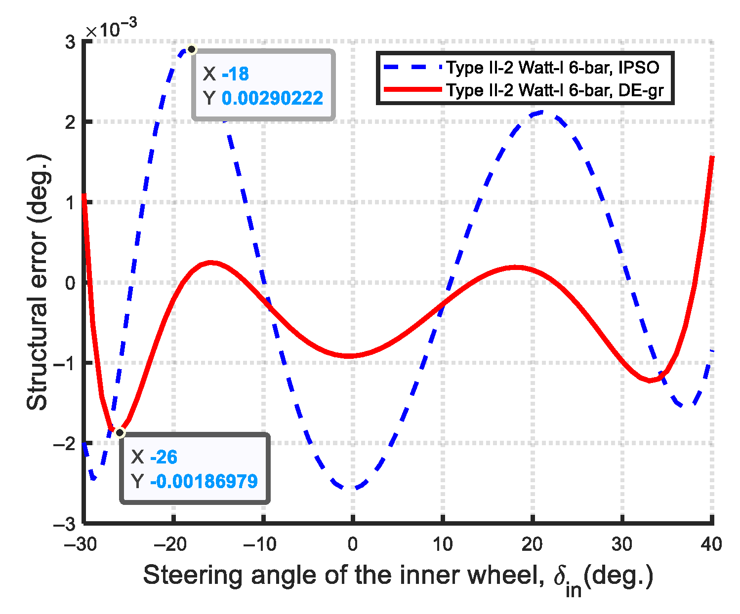
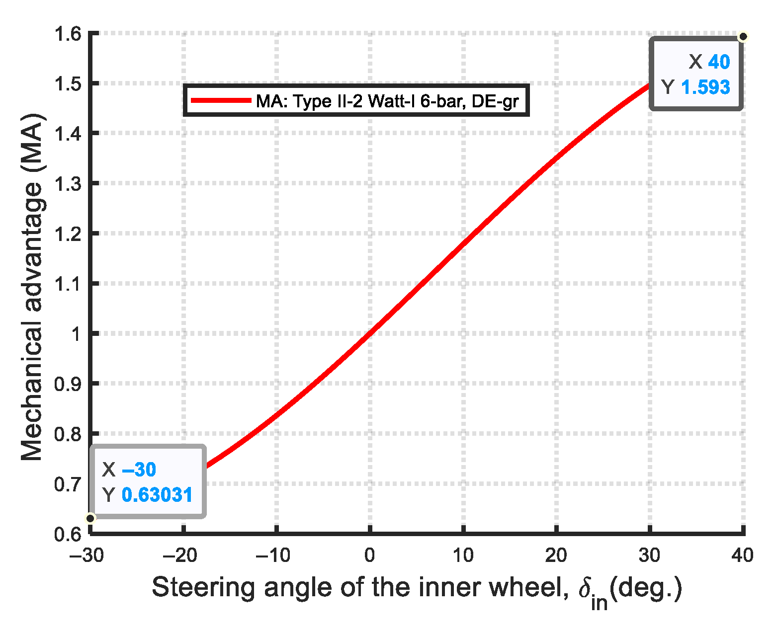
The optimal results for the Type II-2 Watt-I six-bar steering mechanism, obtained using the DE-gr and IPSO methods, are presented in rows 9–12 of Table 7. The DE-gr method yields a lower Min-Max error of 0.0019°, outperforming the IPSO method’s 0.0029°. Both methods exhibit superior synthesis accuracy and outperform those reported in previous studies [8,17]. Figure 58 compares the structural error curves of the optimal mechanisms obtained by both algorithms. Figure 59 and Figure 60 illustrate the kinematic analysis results of the optimal Type II-2 Watt-I six-bar steering mechanism, synthesized using the DE-gr method. As shown in Figure 59, the mechanical advantage (MA) curve ranges from a maximum of 1.5926 to a minimum of 0.630445, indicating effective force transmission throughout the motion cycle. Figure 60 presents the kinematic simulation of the optimal Type II-2 Watt-I six-bar steering mechanism conducted in ADAMS v2015, validating both the steering performance and practical feasibility of the synthesized mechanism. The video of kinematic simulation can be downloaded in Supplementary File.
(3)
Optimal synthesis results of the Type II-3
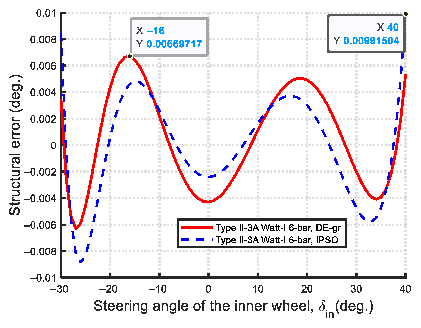
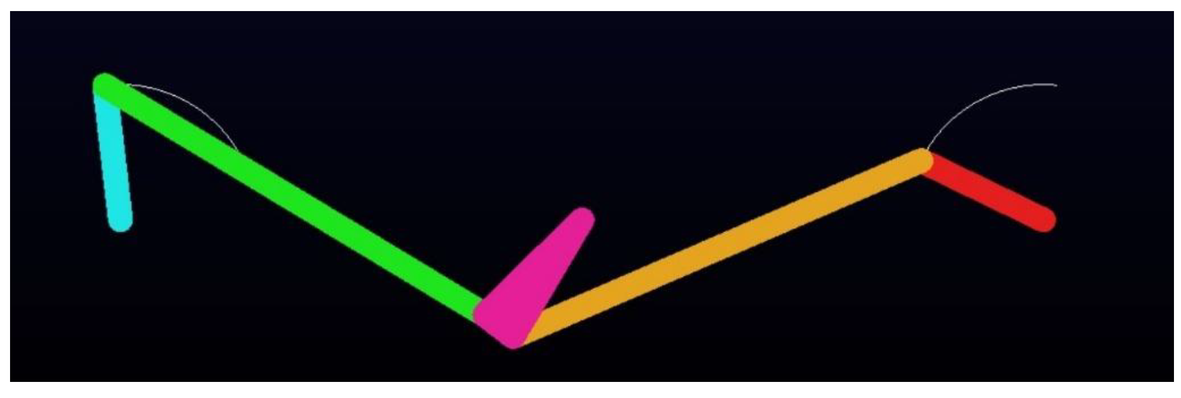
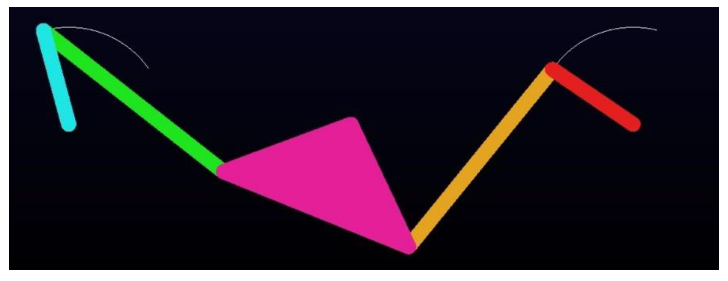
The Type II-3 Watt-I six-bar steering mechanism, shown in Figure 9, includes two cases under investigation: one with four design variables (Type II-3A) and another with five design variables (Type II-3B). For the optimal synthesis of the Type II-3 mechanisms, both the DE-gr and IPSO methods use a population size of 10, 200 iterations, and 100 experimental trials. The optimal synthesis results of the Type II-3A and Type II-3B Watt-I six-bar steering mechanism, obtained using the DE-gr and IPSO methods, are presented in rows 13–16 and 17–20 of Table 7, respectively. Figure 61 compares the structural error curves of the mechanisms optimized by both algorithms for Type II-3A mechanism. The DE-gr method yields a lower Min-Max error of 0.0067, compared to the 0.0099 obtained for the IPSO method, demonstrating superior performance. Both methods exhibit high synthesis accuracy and outperform those reported in previous studies [27,29]. Figure 62 compares the structural error curves of the mechanisms optimized by both algorithms for the Type II-3B mechanism. The IPSO method achieves a lower Min-Max steering error of 0.0059 compared to the 0.0094 obtained for the DE-gr method, indicating superior accuracy. Figure 63 and Figure 64 show the kinematic simulations of the optimal Type II-3A and Type II-3B Watt-I six-bar steering mechanisms, optimized by the DE-gr and IPSO methods, respectively. Conducted in ADAMS v2015, these simulations confirm the steering performance and practical feasibility of the synthesized mechanism.

6. Discussion

For comparison purposes, a summary of the optimal dimensional synthesis results for all Ackermann steering mechanism and Watt-I six-bar steering mechanisms is presented in Table 8. The table includes key information, such as the Min-Max structural error, maximum and minimum mechanical advantage (MAmax/MAmin), population sizes of DE-gr/IPSO, Non-Grashof/Grashof mechanism of the constituent four-bar linkages, maximum number of iterations and experiments (Itmax/Exp.), and the optimization method that achieved the best Min-Max steering error.
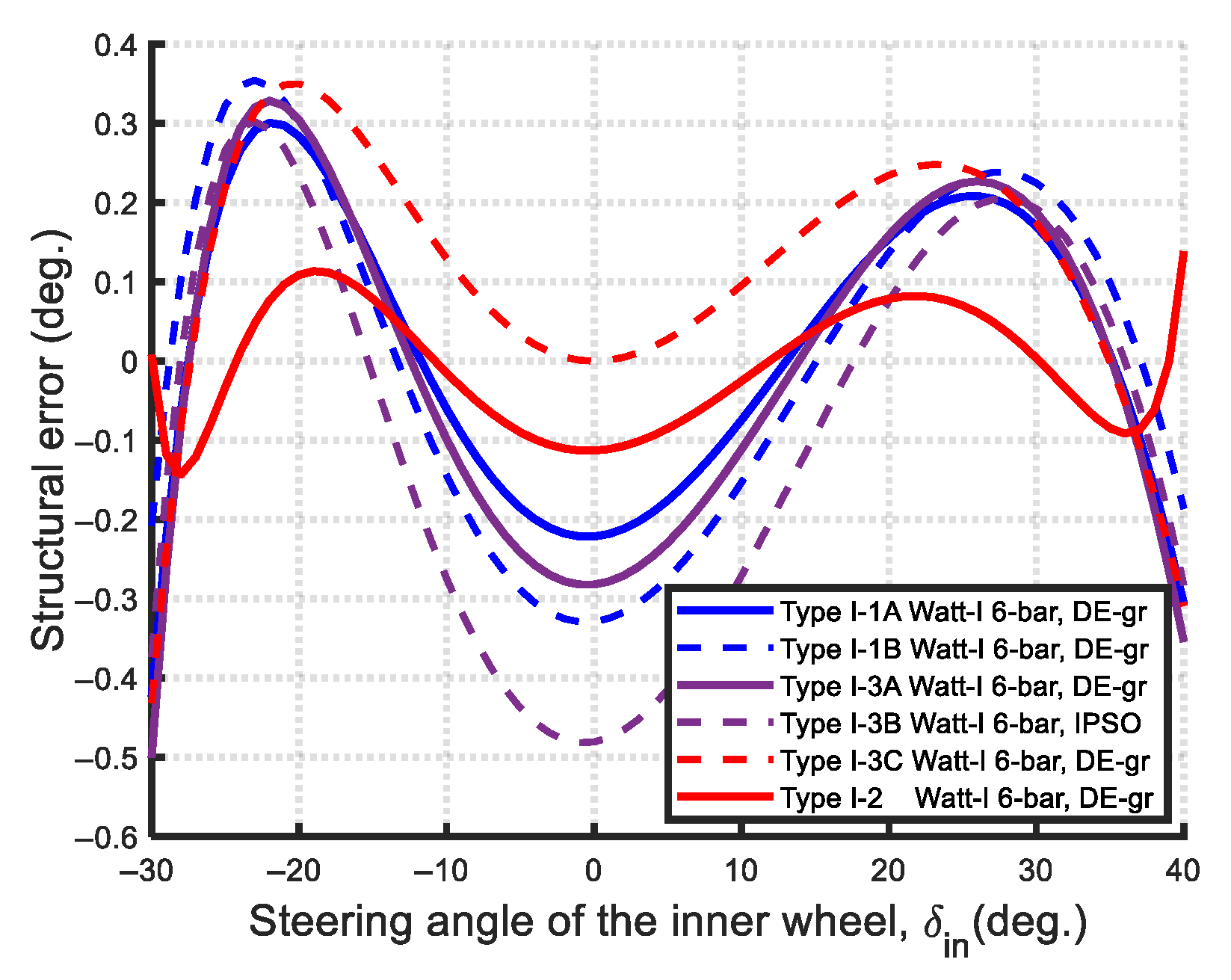
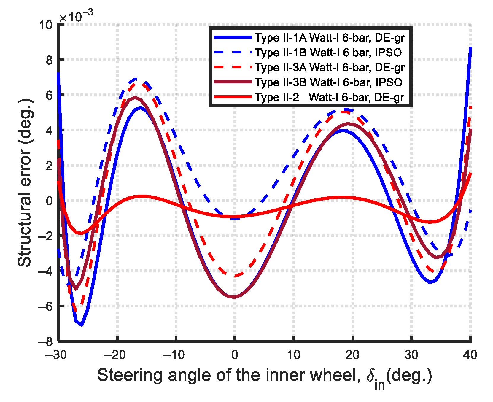
The structural error curves for all the optimal Type I and Type II Watt-I six-bar steering mechanisms are compared in Figure 65 and Figure 66, respectively. The results reveal that the optimal Type I-2 mechanism, synthesized using the DE-gr method, achieves the lowest Min-Max structural error among the six Type I cases. Similarly, the optimal Type II-2 mechanism, also obtained using the DE-gr method, exhibits the smallest Min-Max structural error among the five Type II cases. These findings highlight the superior performance of the DE-gr method in minimizing structural error for both steering mechanism types.
Figure 67 and Figure 68 present comparisons of the structural error curves and mechanical advantage curves, respectively, for the optimal Ackermann steering mechanism, Type I-2, and Type II-2 Watt-I six-bar steering mechanisms.
Based on the optimal synthesis results from Table 8 and Figure 65, Figure 66, Figure 67 and Figure 68, several key observations can be made:
(1)
Ackermann-like Watt-I mechanisms (equal-length steering links, Non-Grashof): The optimal Ackermann-like Watt-I six-bar steering mechanisms—specifically, Type I-1A, Type I-3A, Type I-3C, Type II-1A, and Type II-3A—all consisted of Non-Grashof four-bar linkages with equal-length steering links ( r 4 = r 2 ) , a similar characteristic to that of the Ackermann steering mechanism. Notably, all these optimal designs were synthesized using the DE-gr method.
(2)
Non-Ackermann-like Watt-I mechanisms (unequal-length steering links, Grashof/Non-Grashof): The Non-Ackermann-like Watt-I six-bar mechanisms—including Type I-1B, Type I-2, Type I-3B, Type II-1B, Type II-2, and Type II-3B—feature unequal-length links ( r 4 r 2 ) . Among these, the constituent four-bar linkages in Type I-1B, I-3B, II-1B, and II-3B exhibit Non-Grashof mechanisms, while in Type I-2 and II-2 are Grashof four-bar linkages. The presence of Grashof mechanisms in Non-Ackermann-like Watt-I mechanisms is reported here for the first time.
(3)
Steering accuracy (Min-Max structural error): In terms of steering accuracy, all eleven Watt-I six-bar mechanisms outperform the Ackermann mechanism based on the Min-Max structural error metric. As shown in Figure 67, the optimal Type II-2 mechanism achieves a remarkably low steering error of 0.0019, which is two orders of magnitude lower than that of the Type I-2 mechanism (0.1431), and approximately 1% of its value—demonstrating near-perfect satisfaction of the Ackermann condition.
(4)
Transmission efficiency (mechanical advantage): The maximum mechanical advantage (MAmax) serves as an indicator of transmission efficiency. The Ackermann steering mechanism exhibits the highest MAmax among all synthesis cases, but also the lowest MAmin, indicating greater variation and less uniform efficiency. As shown in Figure 68, the MA values across all mechanisms are comparable within the steering range of [−23°, 25°]. However, in the interval of [−30°, −23°], the Watt-I six-bar mechanisms exhibit higher MA values than the Ackermann mechanism. Conversely, in the [25°, 40°] range, the Ackermann mechanism demonstrates notably higher MA values. Notably, within the [35°, 40°] interval, the MA values of Type I-2 decline sharply, reaching a minimum of 1.2.
(5)
Comparison between Type I and Type II Watt-I mechanisms: Among the Watt-I six-bar mechanisms, Type I designs generally achieve higher maximum mechanical advantage (MAmax) values but lower minimum mechanical advantage (MAmin) values compared to Type II designs. The Type I-3A mechanism demonstrates the highest MAmax (1.8729), but also the lowest MAmin (0.5389). In contrast, the Type II-1A mechanism exhibits the lowest MAmax (1.5831) while achieving the highest MAmin (0.6334), indicating a more consistent mechanical efficiency. With the exception of the Type I-2 mechanism, all Type I designs exceed Type II designs in terms of MAmax, but fall behind in MAmin.
(6)
Comparison of optimization methods (DE-gr vs. IPSO): Both DE-gr and IPSO methods proved effective in achieving optimal solutions. For the Ackermann steering synthesis, which involves two design variables, IPSO performed slightly better. However, for the more complex Watt-I six-bar mechanisms—featuring up to six design variables—DE-gr demonstrated superior efficiency and robustness. For a fair comparison of convergence efficiency and precision between the two employed algorithms, the population size (Np) was initially set to a smaller, consistent value (Np = 10 or 20), such as Np = 10 for Type I-3 and II-3 six-bar mechanisms and Np = 20 for Type I-2 and II-2 six-bar mechanisms. However, in Type I-1 and II-1 six-bar mechanisms, DE-gr successfully converged with Np = 10, while IPSO required Np = 20 to achieve feasible solutions. This demonstrates DE-gr’s greater robustness and convergence efficiency with smaller population sizes. Specifically, DE-gr outperformed IPSO in seven out of eleven Watt-I synthesis cases, while IPSO prevailed in three cases, and one case (Type I-3C, two design variables) resulted in a tie. The enhanced performance of the DE-gr method is primarily due to its efficient search strategy and the application of golden ratio-based crossover (0.618) and mutation (0.382) rates, which improve convergence precision.

7. Conclusions

In this study, two well-known metaheuristic optimization algorithms—the Differential Evolution with golden ratio (DE-gr) and the Improved Particle Swarm Optimization (IPSO)—were employed to solve the optimal dimensional synthesis problems of the Ackermann and Watt-I six-bar steering mechanisms for front-wheel-drive, two-axle, four-wheeled vehicles. Based on the results from twelve optimization cases, the following key conclusions are drawn:
(1)
Transmission Efficiency: The mechanical advantage (MA) is considered an indicator of transmission efficiency. A higher maximum mechanical advantage (MAmax) corresponds to greater transmission efficiency. The optimal Ackermann steering mechanism exhibits the highest MAmax among all cases but the lowest minimum mechanical advantage (MAmin), indicating less consistent efficiency compared to the Watt-I six-bar steering mechanisms. Furthermore, in Watt-I six-bar steering mechanism design, with the exception of the Type I-2 design, all Type I designs exceed Type II designs in terms of MAmax, yet fell behind in MAmin, indicating that Type II designs have a more consistent mechanical efficiency.
(2)
Steering Accuracy: The maximum structural error was used to evaluate steering accuracy. All eleven optimized Watt-I six-bar mechanisms outperform the Ackermann mechanism in this regard. Among them, the Type II designs are notably more accurate than the Type I variants. Specifically, the optimal Type II-2 mechanism achieves an exceptionally low maximum steering error of 0.00149, indicating near-perfect adherence to the Ackermann condition—superior even to the results reported in previous studies on central-lever steering mechanisms.
(3)
Novel Linkage Characteristics: Both the optimal Type I-2 and Type II-2 Watt-I six-bar steering mechanisms comprise two symmetric Grashof four-bar linkages with inclined angle β = 0 and unequal-length steering links ( r 4 r 2 ) , and the initial positions of intermediate steering link 4 lies along the longitudinal axis of the vehicle: θ 40 = π 2 or θ 40 = π 2 . These features of Grashof four-bar linkages within Watt-I six-bar steering mechanisms have not been reported in the previous literature and thus represent a key novel finding of this study.
(4)
Practical Trade-Offs: Although Watt-I six-bar steering mechanisms are more complex and costly to manufacture and maintain than the Ackermann mechanism, they offer significantly improved steering accuracy and vehicle maneuverability. When high precision is required and their cost is acceptable, they are recommended for front-wheel-drive vehicles or wheeled mobile robots. Furthermore, considering both steering accuracy and mechanical advantage, the optimal Type I-2 (Figure 5 and Figure 36) and optimal Type II variant designs are preferred for these applications. Among these, Type II-2 designs (Figure 8 and Figure 60) are particularly recommended due to their simple, symmetric, initial configuration with θ 40 = π 2 , and superior steering accuracy.
(5)
Kinematic Simulation: All optimized steering mechanisms were fully kinematically simulated using the multi-body dynamics analysis software ADAMS v2015 to visualize and eliminate improper configurations, validating the accuracy and feasibility of the steering motion.
(6)
Algorithmic Performance: Both the DE-gr and IPSO methods proved to be effective, easily implementable optimization methods with high convergence efficiency for the dimensional synthesis of linkage-type steering mechanisms. Across all twelve optimization cases, both algorithms achieved high-precision solutions within 100 or 200 iterations when using a population size of 10 (for Type I-3 and II-3 designs) or 20 (for Type I-2 and II-2 designs). Notably, in Type I-1 and II-1 designs, DE-gr consistently converged with Np = 10, while IPSO required Np = 20, highlighting DE-gr’s superior robustness with smaller populations. Leveraging golden ratio-based crossover and mutation rates (0.618:0.382), DE-gr also demonstrated faster convergence and higher solution accuracy. Overall, DE-gr outperformed IPSO in seven cases, IPSO prevailed in four, and one case was a tie—indicating a slight overall advantage for DE-gr.
(7)
Future Works: The linkage-type steering mechanisms synthesized by incorporating factors such as the limitations of the maximum transmission angle, minimum turning radius, and mechanical advantage into the multi-objective function—using the metaheuristic optimization methods DE-gr and IPSO—will be the focus of future work. Both optimization algorithms are also well-suited to more complex synthesis tasks, including the dimensional synthesis of eight-bar steering mechanisms for road vehicles, complex multi-link prosthetic devices, and multi-link walking robots for path generation.

Supplementary Materials

The following supporting information can be downloaded at: https://www.mdpi.com/article/10.3390/machines13070589/s1, Video S1: Kinematic simulation of the optimal Type I-2 mechanism (Type I-2_DE12.mp4), Video S2: Kinematic simulation of the optimal Type I-3C mechanism (Type I-3C_DE.mp4), Video S3: Kinematic simulation of the optimal Type II-2 mechanism (T2-2_DE.avi).

Author Contributions

Conceptualization, Y.-H.K.; data curation, Y.-H.K.; formal analysis, Y.-H.K.; investigation, Y.-H.K.; methodology, Y.-H.K. and D.-C.P.; resources, D.-C.P.; software, Y.-H.K. and D.-H.Z.; supervision, Y.-H.K.; validation, Y.-H.K. and D.-C.P.; writing—original draft, Y.-H.K.; writing—review and editing, Y.-H.K. and D.-C.P. All authors have read and agreed to the published version of the manuscript.

Funding

This research received no external funding.

Data Availability Statement

The original contributions presented in this study are included in the article. Further inquiries can be directed to the corresponding author.

Acknowledgments

In this study, the modeling and kinematic simulations of all optimized steering mechanisms using ADAMS v2015 were completed with the assistance of Kuan-Wei Tong who is now at TSMC in Kaohsiung, Taiwan. We sincerely thank him for his valuable contributions.

Conflicts of Interest

The authors declare no conflicts of interest.

References

  1. Paul, B. A reassessment of Grashof’s criterion. J. Mech. Des. 1979, 101, 515–518. [Google Scholar] [CrossRef]
  2. Simionescu, P.A.; Beale, D. Optimum synthesis of the four-bar function generator in its symmetric embodiment: The Ackermann steering linkage. Mech. Mach. Theory 2002, 37, 1487–1504. [Google Scholar] [CrossRef]
  3. Emura, T.; Arakawa, A. A new steering mechanism using noncircular gears. JSME Int. J. Ser. 3 Vib. Control Eng. Eng. Ind. 1992, 35, 604–610. [Google Scholar] [CrossRef]
  4. Zhao, S.; Zhao, J.S.; Feng, Z.J. Design of a pair of noncircular gears meeting Ackermann steering principle. In Proceedings of the 2011 International Conference on Consumer Electronics, Communications and Networks (CECNet), Xianning, China, 16–18 April 2011; IEEE: Piscataway, NJ, USA, 2011; pp. 217–221. [Google Scholar]
  5. Carcaterra, A.; D’Ambrogio, A. Function generating differential mechanism for an exact solution of the steering problem. Mech. Mach. Theory 1998, 33, 535–549. [Google Scholar] [CrossRef]
  6. Chen, Z.F.; Xie, X.L.; Gao, F.; Liu, Z.Y.; Li, Y.Y. Pure rolling steering system design and research for wheeled mobile robot. J. Phys. Conf. Ser. 2019, 1345, 042071. [Google Scholar] [CrossRef]
  7. Simionescu, P.A.; Smith, M.R.; Tempea, I. Synthesis and analysis of the two-loop translational input steering mechanism. Mech. Mach. Theory 2000, 35, 927–943. [Google Scholar] [CrossRef]
  8. De-Juan, A.; Sancibrian, R.; Viadero, F. Optimal synthesis of function generation in steering linkages. Int. J. Automot. Technol. 2012, 13, 1033–1046. [Google Scholar] [CrossRef]
  9. Sleesongsom, S.; Bureerat, S. Multiobjective optimization of a steering linkage. J. Mech. Sci. Technol. 2016, 30, 3681–3691. [Google Scholar] [CrossRef]
  10. Wolfe, W.A. Analytical design of an Ackermann steering mechanism. J. Eng. Ind. 1959, 81, 10–13. [Google Scholar]
  11. Yao, J.; Angeles, J. The kinematic synthesis of steering mechanisms. Trans. Can. Soc. Mech. Eng. 2000, 24, 453–476. [Google Scholar] [CrossRef]
  12. Shariati, M.; Norouzi, M. Optimal synthesis of function generator of four-bar linkages based on distribution of precision points. Meccanica 2011, 46, 1007–1021. [Google Scholar] [CrossRef]
  13. Stoicescu, A.P. On the optimization of an Ackermann steering linkage. University POLITEHNICA of Bucharest. Sci. Bull. Ser. D Mech. Eng. 2013, 75, 59–70. [Google Scholar]
  14. Ettefagh, M.M.; Javash, M.S. Optimal synthesis of four-bar steering mechanism using AIS and genetic algorithms. J. Mech. Sci. Technol. 2014, 28, 2351–2362. [Google Scholar] [CrossRef]
  15. Zhao, J.S.; Liu, X.; Feng, Z.J.; Dai, J.S. Design of an Ackermann-type steering mechanism. Proc. IMechE Part C J. Mech. Eng. Sci. 2013, 227, 2549–2562. [Google Scholar] [CrossRef]
  16. Simionescu, P.A.; Smith, M.R. Initial estimates in the design of central-lever steering linkages. J. Mech. Des. 2002, 124, 646–651. [Google Scholar] [CrossRef]
  17. Pramanik, S. Kinematic synthesis of a six-member mechanism for automotive steering. J. Mech. Des. 2002, 124, 642–645. [Google Scholar] [CrossRef]
  18. Gautam, N.S.; Awadhiya, P. Kinematic Synthesis of a Modified Ackermann Steering Mechanism for Automotive; SAE Technicial Paper Series 2007-01-3636; SAE International: Warrendale, PA, USA, 2007. [Google Scholar]
  19. Soh, G.S.; McCarthy, J.M. The synthesis of six-bar linkages as constrained planar 3R chains. Mech. Mach. Theory 2008, 43, 160–170. [Google Scholar] [CrossRef]
  20. De-Juan, A.; Sancibrian, R. Optimal synthesis of steering mechanisms including transmission angles. In Proceedings of the EUCOMES 08: The Second European Conference on Mechanism Science 2008, Cassino, Italy, 17–20 September 2008; pp. 175–181. [Google Scholar]
  21. Peñuñuri, F.; Peón-Escalante, R.; Villanueva, C.; Pech-Oy, D. Synthesis of mechanisms for single and hybrid tasks using differential evolution. Mech. Mach. Theory 2011, 46, 1335–1349. [Google Scholar] [CrossRef]
  22. Pramanik, S.; Ingle, R.B.; Latey, A.A. Comparative study of steering mechanism for large wheelbase vehicles. Int. J. Veh. Struct. Syst. 2012, 4, 64–68. [Google Scholar] [CrossRef]
  23. Pramanik, S. Kinematic synthesis of a trailing six-member mechanism for automotive steering. Int. J. Automot. Eng. 2013, 3, 577–581. [Google Scholar]
  24. Wang, H.X.; Dai, E.H. Design on double axial steering mechanism of vehicles and research on its steering error properties. Appl. Mech. Mater. 2014, 528, 297–301. [Google Scholar] [CrossRef]
  25. Romero-Núñez, N.N.; Tuiran-Villalba, R.E. Optimization method of a six-bar steering mechanism formulated with natural coordinates. DYNA 2018, 85, 168–173. [Google Scholar] [CrossRef]
  26. Zhou, C.G.; Hua, T.; Wang, H.W.; Wang, X.Y. Design and error analysis of the linkage type steering mechanism for multiple wheel heavy vehicle. Adv. Intell. Syst. Res. 2019, 165, 219–225. [Google Scholar]
  27. Pramanik, S.; Thipse, S.S. Kinematic synthesis of central-lever steering mechanism for four wheel vehicles. Acta Polytech. 2020, 60, 252–258. [Google Scholar] [CrossRef]
  28. Romero-Nuñez, N.N.; Cuta, C.H.P.; Vieira, R.S.; Martins, D. Optimal dimensional synthesis of central-lever steering linkage using natural coordinates as design variables. In Proceedings of the 27th ABCM International Congress of Mechanical Engineering, Florianopolis, SC, Brazil, 4–8 December 2023. [Google Scholar]
  29. Pramanik, S. Minimization of structural error of the steering mechanism of an agricultural harvesting machine. In Advances in Manufacturing Engineering; Lecture Notes in Mechanical Engineering; Springer Nature: Singapore, 2023; pp. 427–435. [Google Scholar]
  30. Tuleshoy, A.; Tuleshoy, E.; Kuatova, M.; Kamal, A.; Kerimkuloy, D. The synthesis of a two-circuit steering mechanism of the Ackermann transport mobile robot. Preprints 2024. [Google Scholar] [CrossRef]
  31. Fahey, S.O.F.; Huston, D.R. A novel automotive steering linkage. J. Mech. Des. 1997, 119, 481–484. [Google Scholar] [CrossRef]
  32. Dooner, D.B. Function generation utilizing an eight-link mechanism and optimized non-circular gear elements with application to automotive steering. Proc. Inst. Mech. Eng. Part C J. Mech. Eng. Sci. 2001, 215, 847–857. [Google Scholar] [CrossRef]
  33. Romero, N.; Flórez, E.; Mendoza, L. Optimization of a multi-link steering mechanism using a continuous genetic algorithm. J. Mech. Sci. Technol. 2017, 31, 3183–3188. [Google Scholar] [CrossRef]
  34. Kang, Y.-H.; Pang, D.-C.; Zeng, Y.-C. Optimal dimensional synthesis of Ackermann steering mechanisms for three-axle, six-wheeled vehicles. Appl. Sci. 2025, 15, 800. [Google Scholar] [CrossRef]
  35. Kang, Y.-H.; Lin, J.-W.; You, W.-C. Comparative study on the synthesis of path-generating four-bar linkages using metaheuristic optimization algorithms. Appl. Sci. 2022, 12, 7368. [Google Scholar] [CrossRef]
  36. Kang, Y.-H.; Huang, H.-C.; Yang, B.-Y. Optimal design and dynamic analysis of a spring-actuated cam-linkage mechanism in a vacuum circuit breaker. Machines 2023, 11, 150. [Google Scholar] [CrossRef]
  37. Yan, H.-S. Mechanisms: Theory and Applications; McGraw-Hill Education: New York, NY, USA, 2015. [Google Scholar]
  38. Kennedy, J.; Eberhart, R.C. Particle swarm optimization. In Proceedings of the International Conference on Neural Networks, Perth, WA, Australia, 27 November–1 December 1995; Volume 4, pp. 1942–1948. [Google Scholar]
  39. Shi, Y.H.; Eberhart, R.C. A modified particle swarm optimizer. In Proceedings of the IEEE 1998 International Conference on Evolutionary Computation, Anchorage, AK, USA, 4–9 May 1998; pp. 69–73. [Google Scholar]
  40. Ratnaweera, A.; Halgamuge, S.K.; Watson, H.C. Self-organizing hierarchical particle swarm optimizer with time-varying acceleration coefficients. IEEE Trans. Evol. Comput. 2004, 8, 240–255. [Google Scholar] [CrossRef]
  41. Storn, R.; Price, K. Differential evolution- a simple and efficient heuristic for global optimization over continuous spaces. J. Glob. Optim. 1997, 11, 341–359. [Google Scholar] [CrossRef]
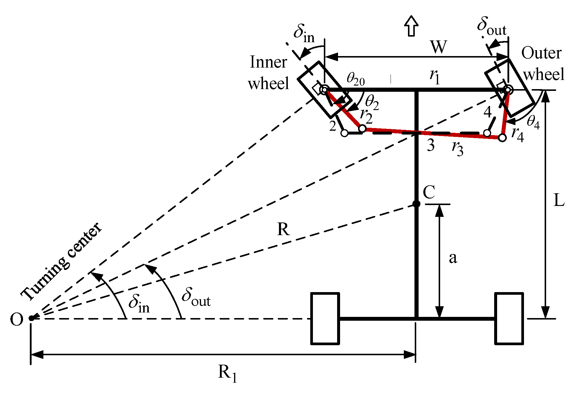
Figure 1. Vehicle turns left, driven by the Ackermann steering mechanism (top view).
Machines 13 00589 g001
Figure 2. Vehicle turns left, driven by the Watt-I six-bar steering mechanism (top view).
Machines 13 00589 g002
Figure 3. Planar Ackermann steering linkage: (a) trailing type (b) leading type.
Machines 13 00589 g003
Figure 4. Type I-1 Watt-I six-bar steering mechanism ( h 0 , β 0 ) .
Machines 13 00589 g004
Figure 5. Type I-2 Watt-I six-bar steering linkage ( h 0 , β = 0 , θ 40 = π / 2 ) .
Machines 13 00589 g005
Figure 6. Type I-3 Watt-I six-bar steering linkage ( h = 0 , β 0 , θ 3 o = θ 5 o = 0 ° ) .
Machines 13 00589 g006
Figure 7. Type II-1 Watt-I six-bar steering linkage ( h 0 , β 0 ) .
Machines 13 00589 g007
Figure 8. Type II-2 Watt-I six-bar steering linkage ( h 0 , β = 0 , θ 40 = π / 2 ) .
Machines 13 00589 g008
Figure 9. Type II-3 Watt-I six-bar steering linkage ( h = 0 , β 0 ) .
Machines 13 00589 g009
Figure 10. Instantaneous centers of the Type II-1 Watt-I six-bar steering mechanism.
Machines 13 00589 g010
Figure 11. Flow chart of the IPSO algorithm.
Machines 13 00589 g011
Figure 12. Flow chart of the DE algorithm.
Machines 13 00589 g012
Figure 13. Convergent curves of both methods for optimizing the Ackermann steering mechanisms.
Machines 13 00589 g013
Figure 14. Structural error curves of the optimal Ackermann steering mechanisms.
Machines 13 00589 g014
Figure 15. Relation curves between the steering angles of outer and inner wheels of the optimal Ackermann steering mechanism.
Machines 13 00589 g015
Figure 16. Actual and ideal output angles of the optimal Ackermann steering mechanisms.
Machines 13 00589 g016
Figure 17. Transmission angle curves of the optimal Ackermann steering mechanism.
Machines 13 00589 g017
Figure 18. Mechanical advantage curve of the optimal Ackermann steering mechanism.
Machines 13 00589 g018
Figure 19. Kinematic simulation of the optimal Ackermann steering mechanism.
Machines 13 00589 g019
Figure 20. Convergent curves of both methods for optimizing Type I-1A six-bar mechanisms.
Machines 13 00589 g020
Figure 21. Structural error curves of the optimal Type I-1A six-bar steering mechanisms.
Machines 13 00589 g021
Figure 22. Relation curves between the steering angles of outer and inner wheels of the optimal Type I-1A six-bar steering mechanism.
Machines 13 00589 g022
Figure 23. Actual and ideal output angles of the optimal Type I-1A six-bar steering mechanism.
Machines 13 00589 g023
Figure 24. Transmission angle curves of the optimal Type I-1A six-bar steering mechanism.
Machines 13 00589 g024
Figure 25. Mechanical advantage curve of the optimal Type I-1A six-bar steering mechanism.
Machines 13 00589 g025
Figure 26. Kinematic simulation of the optimal Type I-1A Watt-I six-bar steering mechanism.
Machines 13 00589 g026
Figure 27. Convergent curves for optimizing the Type I-1B six-bar steering mechanisms.
Machines 13 00589 g027
Figure 28. Structural error curves of the optimal Type I-1B six-bar steering mechanisms.
Machines 13 00589 g028
Figure 29. Relation curve between the steering angles of outer and inner wheels of the optimal Type I-1B six-bar steering mechanism.
Machines 13 00589 g029
Figure 30. Actual and ideal output angles of the optimal Type I-1B six-bar steering mechanism.
Machines 13 00589 g030
Figure 31. Transmission angle curve of the optimal Type I-1B six-bar steering mechanism.
Machines 13 00589 g031
Figure 32. Mechanical advantage curve of the optimal Type I-1B six-bar steering mechanism.
Machines 13 00589 g032
Figure 33. Kinematic simulation of the optimal Type I-1B Watt-I six-bar steering mechanism.
Machines 13 00589 g033
Figure 34. Structural error curves of the optimal Type I-2 six-bar steering mechanisms.
Machines 13 00589 g034
Figure 35. Mechanical advantage curve of the optimal Type I-2 six-bar steering mechanism.
Machines 13 00589 g035
Figure 36. Kinematic simulation of the optimal Type I-2 Watt-I six-bar steering mechanism.
Machines 13 00589 g036
Figure 37. Structural error curves of the optimal Type I-3A six-bar steering mechanisms.
Machines 13 00589 g037
Figure 38. Structural error curves of the optimal Type I-3B six-bar steering mechanisms.
Machines 13 00589 g038
Figure 39. Kinematic simulation of the optimal Type I-3A six-bar steering mechanism.
Machines 13 00589 g039
Figure 40. Kinematic simulation of the optimal Type I-3B six-bar steering mechanism.
Machines 13 00589 g040
Figure 41. Structural error curves of the optimal Type I-3C six-bar steering mechanisms.
Machines 13 00589 g041
Figure 42. Mechanical advantage curve of the optimal Type I-3C six-bar steering mechanism.
Machines 13 00589 g042
Figure 43. Kinematic simulation of the optimal Type I-3C Watt-I six-bar steering mechanism.
Machines 13 00589 g043
Figure 44. Convergent curves for optimizing the Type II-1A six-bar steering mechanisms.
Machines 13 00589 g044
Figure 45. Structural error curves of the optimal Type II-1A six-bar steering mechanisms.
Machines 13 00589 g045
Figure 46. Relation curves between the steering angles of outer and inner wheels of the optimal Type II-1A six-bar steering mechanism.
Machines 13 00589 g046
Figure 47. Actual and ideal output angles of the optimal Type II-1A six-bar steering mechanism.
Machines 13 00589 g047
Figure 48. Transmission angle curves of the optimal Type II-1A six-bar steering mechanism.
Machines 13 00589 g048
Figure 49. Mechanical advantage curve of the optimal Type II-1A six-bar steering mechanism.
Machines 13 00589 g049
Figure 50. Kinematic simulation of the optimal Type II-1A Watt-I six-bar steering mechanism.
Machines 13 00589 g050
Figure 51. Convergent curves for optimizing the Type II-1B six-bar steering mechanisms.
Machines 13 00589 g051
Figure 52. Structural error curves of the optimal Type II-1B six-bar steering mechanisms.
Machines 13 00589 g052
Figure 53. Relation curves between the steering angles of outer and inner wheels of the optimal Type II-1B six-bar steering mechanism.
Machines 13 00589 g053
Figure 54. Actual and ideal output angles of the optimal Type II-1B six-bar steering mechanism.
Machines 13 00589 g054
Figure 55. Transmission angle curves of the optimal Type II-1B six-bar steering mechanism.
Machines 13 00589 g055
Figure 56. Mechanical advantage curve of the optimal Type II-1B six-bar steering mechanism.
Machines 13 00589 g056
Figure 57. Kinematic simulation of the optimal Type II-1B Watt-I six-bar steering mechanism.
Machines 13 00589 g057
Figure 58. Structural error curves of the optimal Type II-2 six-bar steering mechanisms.
Machines 13 00589 g058
Figure 59. Mechanical advantage curve of the optimal Type II-2 six-bar steering mechanism.
Machines 13 00589 g059
Figure 60. Kinematic simulation of the optimal Type II-2 Watt-I six-bar steering mechanism.
Machines 13 00589 g060
Figure 61. Structural error curves of the optimal Type II-3A six-bar steering mechanism.
Machines 13 00589 g061
Figure 62. Structural error curves of the optimal Type II-3B six-bar steering mechanisms.
Machines 13 00589 g062
Figure 63. Kinematic simulation of the optimal Type II-3A Watt-I six-bar steering mechanism.
Machines 13 00589 g063
Figure 64. Kinematic simulation of the optimal Type II-3B Watt-I six-bar steering mechanism.
Machines 13 00589 g064
Figure 65. Structural error curves of all optimal Type I Watt-I six-bar steering mechanisms.
Machines 13 00589 g065
Figure 66. Structural error curves of all optimal Type II Watt-I six-bar steering mechanisms.
Machines 13 00589 g066
Figure 67. Comparison of structural error curves for the optimal Ackermann and Watt-I six-bar steering mechanisms.
Machines 13 00589 g067
Figure 68. Comparison of MA curves for the optimal Ackermann and Watt-I six-bar steering mechanisms.
Machines 13 00589 g068
Table 1. Eleven design cases for the optimal synthesis of the Watt-I six-bar mechanisms.
Type of the Watt-I Six-Bar Steering MechanismVariable NumberDesign VectorGeometry Conditions
Type I-1Type I-1A5 X = [ r 2 , r 3 , h , β , θ 20 ] T h 0 , β 0 , r 4 = r 2 .
Type I-1B6 X = [ r 2 , r 3 , r 4 , h , β , θ 20 ] T h 0 , β 0 , r 4 r 2 .
Type I-2Type I-25 X = [ r 2 , r 3 , r 4 , h , θ 20 ] T h 0 , β = 0 , θ 40 = π / 2 , r 4 r 2 .
Type I-3Type I-3A4 X = [ r 2 , r 3 , β , θ 2 o ] T h = 0 , β 0 , r 4 = r 2 .
Type I-3B5 X = [ r 2 , r 3 , r 4 , β , θ 2 o ] T h = 0 , β 0 , r 4 r 2 .
Type I-3C2 X = [ r 2 , θ 2 o ] T h = 0 , β 0 , r 4 = r 2 ,
θ 3 o = θ 5 o = 0 ° .
Type II-1Type II-1A5 X = [ r 2 , r 3 , h , β , θ 20 ] T h 0 , β 0 , r 4 = r 2 .
Type II-1B6 X = [ r 2 , r 3 , r 4 , h , β , θ 20 ] T h 0 , β 0 , r 4 r 2 .
Type II-2Type II-25 X = [ r 2 , r 3 , r 4 , h , θ 20 ] T h 0 , β = 0 , θ 40 = π / 2 , r 4 r 2 .
Type II-3Type II-3A4 X = [ r 2 , r 3 , β , θ 20 ] T h = 0 , β 0 , r 4 = r 2 .
Type II-3B5 X = [ r 2 , r 3 , r 4 , β , θ 20 ] T h = 0 , β 0 , r 4 r 2 .
Table 2. The parameter settings for two optimization parameters.
AlgorithmDE-grIPSO
Population size (Np)10/2010/20
Iteration times100/200100/200
Experimental times 100100
Mutation methodDE/best/1
DE/best/2
--
Mutation factor0.382--
Crossover method Exponential crossover--
Crossover rate (CR)0.618--
Selection methodCompetitive selection--
Learning factor ( C 1 , C 2 )--0.5  C 1 , C 2 2.5
Inertia weighting (w)--0.4 w 0.9
Table 3. Optimal Ackermann steering mechanisms obtained by two optimization methods.
Obj. Fun r 1 r 2 r 3 r 4 θ 20 MAmax/MAminMin-Max Error
DE-gr3.646 × 10−51480.00100.0001410.9531100.00069.80392.0982/0.47381.1160
IPSO3.590 × 10−51480.0085.63201420.460285.101769.65642.0917/0.47561.0944
Table 4. The design information for optimal design of the Type I Watt-I six-bar steering mechanisms.
Type I Watt-I Six-Bar Steering MechanismGeometric Relations/
Design Vector
Range of the Design Parameters
Unit : mm ( length ) ,   ° (Angle)
The Constituent Four-Bar Linkage
Type I-1A
Ackermann-like
h 0 , β 0 , r 4 = r 2 . [ r 2 , r 3 , h , β , θ 20 ] 150 r 2 , r 3 , 1000 , 400 h 400 , 0 < β 120 , 30 θ 20 130 . Non-Grashof mechanism
Type I-1B
Non-Ackermann-like
h 0 , β 0 , r 4 r 2 . [ r 2 , r 3 , r 4 , h , β , θ 20 ] 150 r 2 , r 3 , r 4 1000 , 400 h 400 , 0 < β 120 , 30 θ 20 130 . Non-Grashof mechanism
Type I-2
Non-Ackermann-like
h 0 , β = 0 , r 4 r 2 , θ 40 = π / 2 . [ r 2 , r 3 , r 4 , h , θ 20 ] 100 r 2 , r 3 , r 4 1000 , 250 h 250 , 30 θ 20 130 . Grashof mechanism
Type I-3A
Ackermann-like
h = 0 , β 0 , r 4 = r 2 . [ r 2 , r 3 , β , θ 2 o ] 100 r 2 , r 3 1000 , 10 β 120 , 30 θ 20 120 . Non-Grashof mechanism
Type I-3B
Non-Ackermann-like
h = 0 , β 0 , r 4 r 2 . [ r 2 , r 3 , r 4 , β , θ 2 o ] 100 r 2 , r 3 , r 4 1000 , 10 β 120 , 30 θ 20 120 . Non-Grashof mechanism
Type I-3C
Ackermann-like
h = 0 , β 0 , r 4 = r 2 , θ 3 o = θ 5 o = 0 ° . [ r 2 , θ 2 o ] 100 r 2 1000 , 30 θ 20 120 , θ 3 o = θ 5 o = 0 ° . Non-Grashof mechanism
Table 5. Optimal results of the Type I six-bar steering mechanisms synthesized by two methods.
                      Type I-1A: ( h 0 , β 0 , r 4 = r 2 ) ,   X = [ r 2 , r 3 , h , β , θ 20 ] T
Obj. fun r 1 r 2 r 3 r 4 h β θ 20 Min-Max
error
DE-gr9.597 × 10−7762.9638461.8052999.9605461.8052185.77880.8596120.06090.4233
IPSO1.47 × 10−5771.6305181.0549845.3780181.0549218.66310.9378113.93340.4690
                      Type I-1B: ( h 0 , β 0 , r 4 r 2 ) ,   X = [ r 2 , r 3 , r 4 , h , β , θ 20 ] T
Obj. fun r 1 r 2 r 3 r 4 h β θ 20 Min-Max
error
DE-gr1.400 × 10−5798.3499421.9384995.2772421.9719299.604013.0402123.35780.3544
IPSO2.732 × 10−5743.0465405.5785835.8964406.3062−67.216438.7673124.37030.4898
                      Type I-2: ( h 0 , β = 0 , r 4 r 2 ,   θ 40 = π / 2 ) ,   X = [ r 2 , r 3 , r 4 , h , θ 20 ] T
Obj. fun r 1 r 2 r 3 r 4 h β θ 20 Min-Max
error
DE-gr1.749 × 10−6753.6278478.2386999.8593199.4626142.67030.0000122.59540.1431
IPSO2.686 × 10−6742.1067305.8035894.1713135.705055.87850.0000119.52920.1546
                      Type I-3A: ( h = 0 , β 0 , r 4 = r 2 ) ,   X = [ r 2 , r 3 , β , θ 2 o ] T
Obj. fun r 1 r 2 r 3 r 4 h β θ 20 Min-Max
error
DE-gr1.289 × 10−5740.0000400.5041907.5244400.50410.000010.0000119.96860.5002
IPSO9.951 × 10−5740.0000482.1574957.7717482.15740.000051.570690.69750.5219
                      Type I-3B: ( h = 0 , β 0 , r 4 r 2 ) ,   X = [ r 2 , r 3 , r 4 , β , θ 2 o ] T
Obj. fun r 1 r 2 r 3 r 4 h β θ 20 Min-Max
error
DE-gr1.252 × 10−5740.000298.7328863.9833350.92150.000010.0620109.73000.5512
IPSO2.172 × 10−5740.000324.0593856.9544346.45440.000016.1074109.73000.4814
                      Type I-3C: ( h = 0 , β 0 , r 4 = r 2 ) , ( θ 3 o = θ 5 o = 0 ° ) ,   X = [ r 2 , θ 20 ] T
Obj. fun r 1 r 2 r 3 r 4 h β θ 20 Min-Max
error
DE-gr9.027 × 10−6740.000736.37131237.181736.37130.0000−39.46109.73000.4311
IPSO9.027 × 10−6740.000736.37131237.181736.37130.0000−39.46109.73000.4311
Table 6. Design information for the optimal design of Type II Watt-I six-bar steering mechanisms.
Type II Watt-I Six-Bar Steering MechanismGeometric Relations/
Design Vector
Range of the Design Parameters
Unit : mm ( length ) ,   ° (Angle)
The Constituent Four-Bar Linkage
Type II-1A
Ackermann-like
h 0 , β 0 , r 4 = r 2 . [ r 2 , r 3 , h , β , θ 20 ] 100 r 2 800 , 300 r 3 1200 , 500 h 500 , 30 β 120 , 30 θ 20 120 . Non-Grashof
mechanism
Type II-1B
Non-Ackermann-like
h 0 , β 0 , r 4 r 2 . [ r 2 , r 3 , r 4 , h , β , θ 20 ] 100 r 2 , r 4 800 , 300 r 3 1200 , 500 h 500 , 30 β 120 , 30 θ 20 120 . Non-Grashof
mechanism
Type II-2
Non-Ackermann-like
h 0 , β = 0 , θ 40 = π / 2 . [ r 2 , r 3 , r 4 , h , θ 20 ] 80 r 2 , r 3 1000 , 80 r 4 700 , 200 h 500 , 30 θ 20 120 . Grashof mechanism
Type II-3A
Ackermann-like
h = 0 , β 0 , r 4 = r 2 . [ r 2 , r 3 , β , θ 20 ] 100 r 2 1000 , 100 r 3 1000 , 10 β 120 , 30 θ 20 120 . Non-Grashof
mechanism
Type II-3B
Non-Ackermann-like
h = 0 , β 0 , r 4 r 2 . [ r 2 , r 3 , r 4 , β , θ 20 ] 100 r 2 , r 3 , r 4 1000 , 10 β 120 , 30 θ 20 120 . Non-Grashof
mechanism
Table 7. Optimal results of Type II Watt-I six-bar steering mechanisms, obtained by two methods.
                                Type II-1A: ( h 0 , β 0 , r 4 = r 2 ) ,   X = [ r 2 , r 3 , h , β , θ 20 ] T
Obj. fun r 1 r 2 r 3 r 4 h β θ 20 Min-Max.
error
DE-gr2.082 × 10−8875.7030272.8332829.9922272.8332−468.248114.453336.28840.0087
IPSO2.235 × 10−8740.3005226.9415703.0517226.941521.090239.586767.57690.0175
                                Type II-1B: ( h 0 , β 0 , r 4 r 2 ) ,   X = [ r 2 , r 3 , r 4 , h , β , θ 20 ] T
Obj. fun r 1 r 2 r 3 r 4 h β θ 20 Min-Max. error
DE-gr1.093 × 10−7891.1493293.2764532.3469623.1802496.535178.8091115.36260.0366
IPSO3.843 × 10−9745.8287258.1550630.1374347.422293.061557.934962.27680.0069
                                Type II-2: ( h 0 , β = 0 , θ 40 = π / 2 ) ,   X = [ r 2 , r 3 , r 4 , h , θ 2 o ] T
Obj. fun r 1 r 2 r 3 r 4 h β θ 20 Min-Max. error
DE-gr1.77 × 10−10835.8608326.5826745.1541619.7032388.66860.000055.146990.0019
IPSO8.99 × 10−10809.5860296.6413732.0895488.1507328.37410.000061.63310.0029
                                Type II-3A: ( h = 0 , β 0 , r 4 = r 2 ) ,   X = [ r 2 , r 3 , β , θ 2 o ] T
Obj. fun r 1 r 2 r 3 r 4 h β θ 20 Min-Max. error
DE-gr4.28 × 10−9740.0000218.5374713.2952218.53740.000015.022456.60990.0067
IPSO4.56 × 10−9740.0000231.0028700.2822231.00280.000047.569367.14930.0099
                                Type II-3B: ( h = 0 , β 0 , r 4 r 2 ) ,   X = [ r 2 , r 3 , r 4 , β , θ 2 o ] T
Obj. fun r 1 r 2 r 3 r 4 h β θ 20 Min-Max. error
DE-gr4.28 × 10−9740.0000250.5453658.1444317.33210.000056.975055.13960.0094
IPSO3.72 × 10−9740.0000256.0664601.1974357.05530.000094.593565.01700.0059
Table 8. Information regarding the results of all the optimal dimensional synthesis of steering mechanisms.
Type of Steering
Mechanism
Min-Max Structural
Error   ( ° )
MAmax/MAminConstituent Four-Bar
Linkages
Population Sizes of
DE-gr/IPSO
Itmax/ExpWinner of Optimal Method
Ackermann steering
mechanism
1.10792.0917/0.4756Non-Grashof
mechanism
10/10200/100IPSO
Watt-I six-bar steering
mechanism
Type I-1A
(Ackermann-like)
0.42331.8308/0.5514Non-Grashof mechanism10/20100/100DE-gr
Type I-1B
(Non-Ackermann-like)
0.35441.8121/0.5594Non-Grashof mechanism10/20100/100DE-gr
Type I-2
(Non-Ackermann-like)
0.14311.5806/0.6326Grashof
mechanism
20/20200/100DE-gr
Type I-3A
(Ackermann-like)
0.50021.8729/0.5389Non-Grashof mechanism10/10200/100DE-gr
Type I-3B
(Non-Ackermann-like)
0.48141.8574/0.5452Non-Grashof mechanism10/10200/100IPSO
Type I-3C
(Ackermann-like)
0.43111.8157/0.5553Non-Grashof mechanism10/10100/100DE-gr,
IPSO
Type II-1A
(Ackermann-like)
0.00871.5831/0.6334Non-Grashof mechanism10/20100/100DE-gr
Type II-1B
(Non-Ackermann-like)
0.00691.5919/0.6305Non-Grashof mechanism10/20100/100IPSO
Type II-2
(Non-Ackermann-like)
0.00191.5930/0.6301Grashof
mechanism
20/20200/100DE-gr
Type II-3A
(Ackermann-like)
0.00671.5859/0.6325Non-Grashof mechanism10/10200/100DE-gr
Type II-3B
(Non-Ackermann-like)
0.00591.5878/0.6319Non-Grashof mechanism10/10200/100IPSO
Disclaimer/Publisher’s Note: The statements, opinions and data contained in all publications are solely those of the individual author(s) and contributor(s) and not of MDPI and/or the editor(s). MDPI and/or the editor(s) disclaim responsibility for any injury to people or property resulting from any ideas, methods, instructions or products referred to in the content.