Abstract
Tread braking is still extensively used on freight wagons due to lower purchasing and maintenance costs compared to disk braking. Cast iron brake blocks were replaced by composite materials (organic or sintered) that result in a lower wheel roughness, reducing rolling noise. Unfortunately, composite brake blocks have a lower thermal conductivity, negatively affecting the wheel mechanical behavior as the braking energy is almost entirely dissipated by the wheels, which are therefore subjected to higher temperatures. Mechanical properties of the wheel material, such as yield stress and Rolling Contact Fatigue (RCF) behavior, markedly decrease with temperature, resulting in higher wear rates and wheel tread damage. Contacted to analyze defects not clearly defined in the current regulations used for maintenance and inspections, the authors surveyed the literature and the technical documentation about tread-braked wheels. The paper provides an updated view about the state-of-the-art of the research on thermomechanical behavior of railway wheels and discusses the implication of the increased thermal stresses generated by composite brake blocks.
1. Introduction
Wheels are possibly the most stressed component of a railway vehicle, as high vertical, lateral, and longitudinal loads are carried at the wheel–rail contact. These actions are further amplified when wheel tread is used as the braking surface. Even if the pressure applied by the brake blocks on the wheel surface is much lower than the pressure at the wheel–rail contact, tread braking introduces two relevant issues on the wheel surface: a roughness that affects rolling noise and thermal loads that affect the mechanical strength of the wheel.
Drag braking to keep the speed of heavy freight trains within the prescribed limits along long downhill slopes introduces a nearly continuous and intensive energy dissipation at the block/tread surface. Safety concerns are real, as extreme thermal loads may lead to the mechanical failure of the wheel and therefore to derailments, especially for worn wheels in which rim thickness is reduced and the beneficial compressive mean stress resulting from a specific heat treatment applied during manufacturing (rim chilling) is nearly vanished.
Due to some recent major issues involving tread-braked wheels, greater attention to inspections and monitoring activities is paid by Railway Undertakings (RUs), i.e., the enterprise that hauls the wagons, and the authors were contacted to evaluate some borderline cases that caused controversial discussions between RUs and the wagon’s owner (the “keeper”).
This paper describes the state-of-the-art of tread-braked wheels arising from that activity, considering in Section 2 the needs and the developments that bring to the current practice using monobloc wheels and composite brake blocks. A review about the mechanical behavior of wheel material at high temperatures is shown in Section 3, while literature about tests and simulations aimed at finding the actual wheel temperatures is analyzed in Section 4. Finally, real-life wagon inspection common practice and documentation are reviewed in Section 5, introducing a defect not previously described.
2. Cast Iron Brake Blocks vs. Composite Brake Blocks
2.1. The Problem of Tyred Wheels
High-phosphorous P10 cast iron is the conventional material used for brake blocks. Their in-service behavior is known, including the possible damages induced on the wheel tread and their management. The main drawbacks of cast iron are the markedly variable coefficient of friction with speed and the high level of tread surface roughness that leads to high rolling noise levels. From the perspective of a reduction in the environmental impact of freight railway traffic, several studies were performed since the 1960s to reduce rolling noise, and different materials for brake blocks were developed. Earlier analysis to evaluate materials alternative to cast iron can be found in the documents published by the UIC (Union Internationale des Chemins de Fer) Office de Recherches et d’Essais (ORE) B64 committee [1] from 1965 to 1971. The lower heat conductivity of composite blocks compared to cast iron was already well known at those times.
As monobloc (or solid) wheels were not adopted for freight wagons that were all equipped with tired wheels, the report ORE B64 Rp5 compares the loosening time of tires due to continuous braking tests with both cast iron and the first type of composite blocks, named K blocks. As shown in Figure 1, these tests resulted in tire loosening times for K blocks (thermal conductivity of 0.88 W/mK) around 50–70% shorter of those obtained with cast iron brake blocks (thermal conductivity of 50 W/mK), and a strong dependency of loosening time on the wheel design parameters (tire thickness and shrink fit interference) was found. The B64 committee concluded by recommending developing composite blocks with higher thermal conductivity.
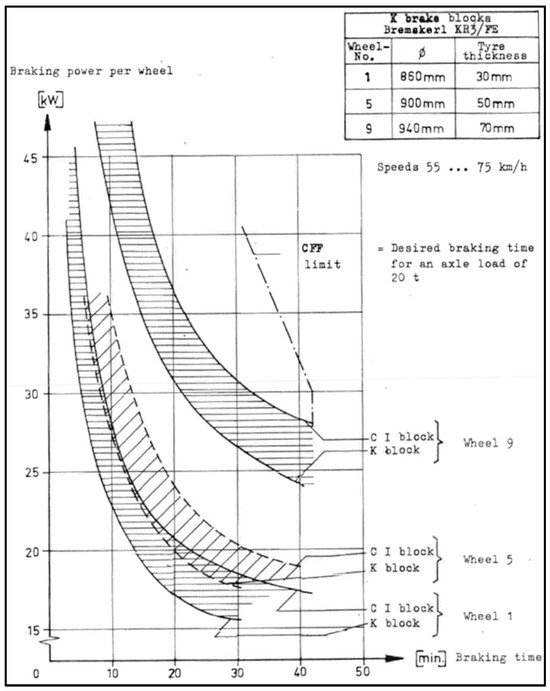
Figure 1.
Tire loosening time as a function of the continuous drag braking power for different tire thickness and brake block material [1].
2.2. The Generalized Adoption of Composite Brake Blocks
Light, thermostable solid wheels were developed to remove the tire-loosening problem while retaining an acceptable geometry after long drag braking. They are designed to withstand high thermal load thanks to a deeply curved web (often called C-shape or S-shape) to minimize both radial stiffness and lateral displacement of the wheel rim. Today, they are designed in Europe according to standard [2] and its application code UIC 510-5 [3], both first published in 2003 and descending from the earlier work by the B169 working group of the ERRI (European Rail Research Institute) in the 1990s [4,5,6,7]. New wagons were equipped only with solid wheels since 1989 [8], and quite recently (2020), tyred wheels were completely removed from service [9].
An updated list of composite blocks approved for use can be found in the UIC 541-4 code [10]. It should be noted that this standard was first released in 1977, under the title “Brakes with composition brake blocks with high friction values for international traffic” and the first K block was approved in 1984. K blocks exhibit a higher and particularly constant coefficient of friction, allowing a redesign (lightening) of the brake rigging, while the operation of trains with a mixed composition of wagons equipped with cast iron and composite blocks resulted in being problematic due to the different braking performance of the two block materials.
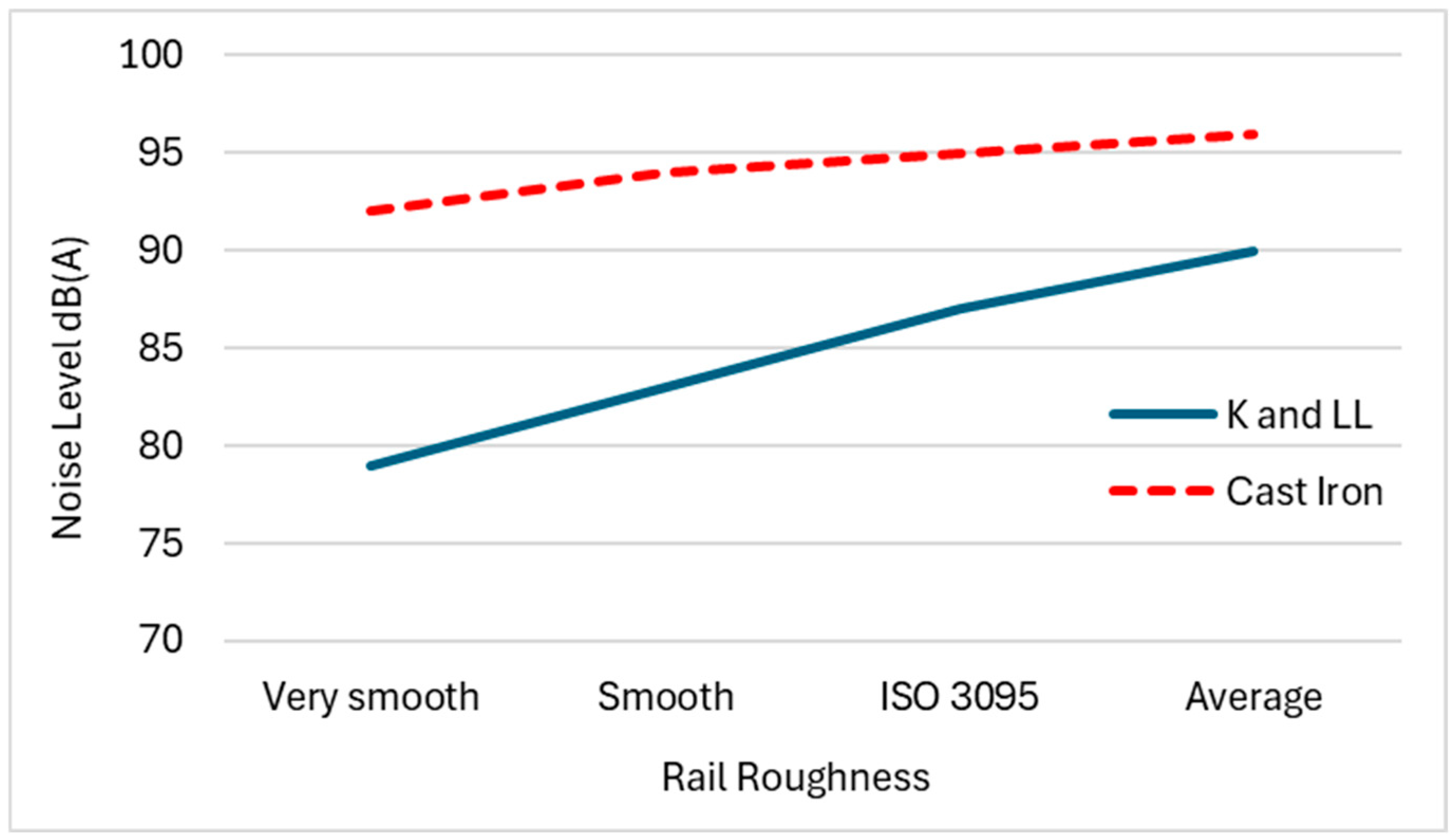
If the tire-loosening problem was solved with the generalized introduction of monobloc wheels, noise remained an issue for cast iron braking. The first Technical Specification for Interoperability (TSI) concerning noise emitted by the rolling stock was published in Europe in December 2005 [11], defining the limit for pass-by noise at 80 km/h of new freight wagons as LpAeq,Tp = 82 dB(A), which was not achievable with conventional cast iron brake blocks, as shown in Figure 2. This led to the decision of a complete replacement of cast iron with composite (sintered and organic) brake blocks. Tests showed that an average noise reduction of 8~10 dB(A) was possible, depending also on rail roughness level [12].
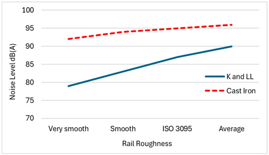
Figure 2.
Noise level from freight wagons with composite (solid blue line) and cast-iron (dashed red line) brake blocks for different rail roughness levels. Adapted from [12].
Composite brake blocks are classified today according to the mean value of the coefficient of friction f [13]:
- high friction (K blocks): f = 0.25–0.30
- medium friction (L blocks): f = 0.15–0.25
- low friction—low noise (LL blocks): f = 0.10–0.15
Specific values of the friction coefficient for cast iron brake blocks are not defined in any UIC standard, as the use of high-phosphorus P10 cast iron [14] guaranteed the braking performance. The friction coefficient of P10 cast iron is also strongly dependent on the sliding velocity, as it increases rapidly as the velocity decreases. This is shown in Figure 3, where the cast iron coefficient of friction f’ is compared to the adhesion at the wheel–rail contact f.
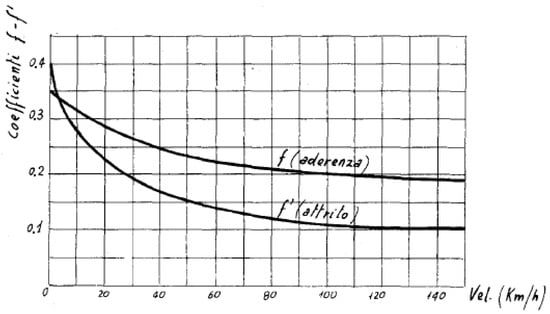
Figure 3.
Friction coefficient of cast iron brake blocks f’ (lower curve) and adhesion at the wheel–rail contact f (upper curve) as function of speed [15].
As already mentioned, the higher coefficient of friction of K blocks is relatively independent from speed, allowing for a reduction in the size and the mass of brake components. L, and later LL, brake blocks were instead specifically developed targeting the friction properties of cast iron and intended to be a straightforward replacement of cast iron blocks on existing freight wagons.
2.3. Thermal and Mechanical Properties of Composite Brake Blocks
Composite brake blocks are made of an abrasive base material that helps polish the wheel tread surface, a friction modifier that adjusts the friction properties by decreasing or increasing the coefficient of friction, a filler used to complete the material structure in terms of mechanical properties, wear and corrosion resistance, and a binder used as bonding [16]. Additives can be either metallic or non-metallic, and the resulting material can therefore be classified as sintered or organic. Organic blocks are made by cold pressing metallic and non-metallic powders using the bonding offered by an organic resin, while in sintered blocks only metallic powders are compressed at high temperatures with the conventional sintering process.
Compared to cast iron, composite brake blocks usually show lower wear of the block itself but higher wear of the wheel, resulting in being more aggressive on the tread as the polishing action reduces wheel roughness (related to noise emission), but it also increases tread wear [17]. Table 1 summarizes the main characteristics in terms of wear behavior of organic and sintered brake blocks with reference to cast iron properties.

Table 1.
Wear behavior of organic and sintered blocks. Values are given with respect to cast iron brake blocks values [17].
With sintered blocks wheels need to be reprofiled more often as the wheel tread tends to become hollow, i.e., with the central part of the tread more worn compared to its adjacent parts, and it leads to a rapid growth of the wheel conicity (described by EN 15302 [18] with a simplified parameter named equivalent conicity) and to a higher risk of wagon instability. According to [19], wheel profiles of wagons fitted with LL brake blocks should be monitored after 100,000 km from reprofiling and then every 50,000 km with the aim to ensure equivalent conicity lower than 0.4.
While sintered brake blocks have a nearly independent wear behavior from the temperature, organic brake blocks show a higher wear rate with increasing temperature, as shown in Figure 4 for three organic blocks, one sintered block, and one cast iron block [17,19]. This property is called fusibility of the block, allowing to protect the wheel from excessive temperatures if failure of the braking system leads to a prolonged, undue braking application (locked brake). For organic blocks fusibility happens at higher temperatures (400–500 °C) compared to cast iron. Moreover, when fusibility occurs, wheel temperature may be higher considering their low thermal conductivity compared to cast iron, and the percentage of heat going into the wheel can be 93–96% [20]. Lower values were described for sintered blocks (86–91%) and for cast iron (76–87%).
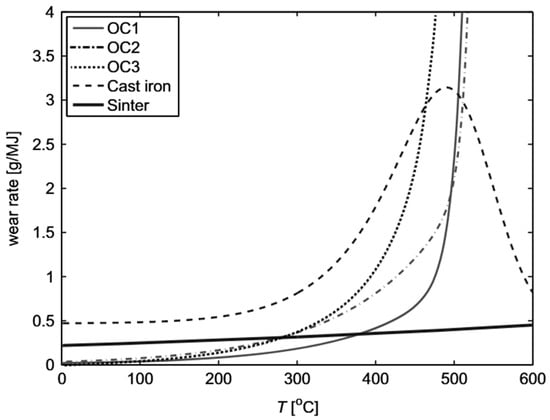
Figure 4.
Wear rate of organic, sintered and cast-iron brake blocks in function of the temperature. Adapted from [17].
3. Mechanical Behavior of Steel Wheels at High Temperatures
Surface and sub-surface tread damages, which are of interest in this paper, occur due to rolling contact. Damage maps (or shakedown diagrams) by K. L. Johnson [21] relate traction coefficient T/N at the wheel–rail contact with the dimensionless quantity p0/k, where p0 is the average contact pressure that can be calculated from Hertz’s theory and k is the material shear yield strength. Adopting the Von Mises equivalent stress criterion, the yield shear stress can be estimated from the yield stress σy as k = σy/√3. In the damage maps, as shown in Figure 5a, three conditions can occur:
- The elastic shakedown: The material returns to an elastic behavior after a few plastic cycles;
- The plastic shakedown: The material remains in a stable plastic cycle;
- The ratchetting: the plastic cycles are not stable and an incremental growth of plastic deformation occurs.
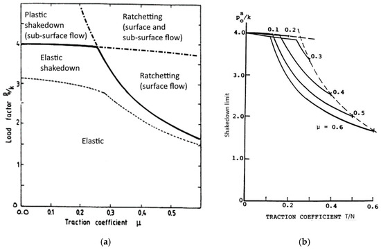
Figure 5.
(a) Shakedown diagram in full slip condition, i.e., T/N = μ; (b) and partial slip condition, i.e., T/N < μ. Modified from [22].
Figure 5.
(a) Shakedown diagram in full slip condition, i.e., T/N = μ; (b) and partial slip condition, i.e., T/N < μ. Modified from [22].
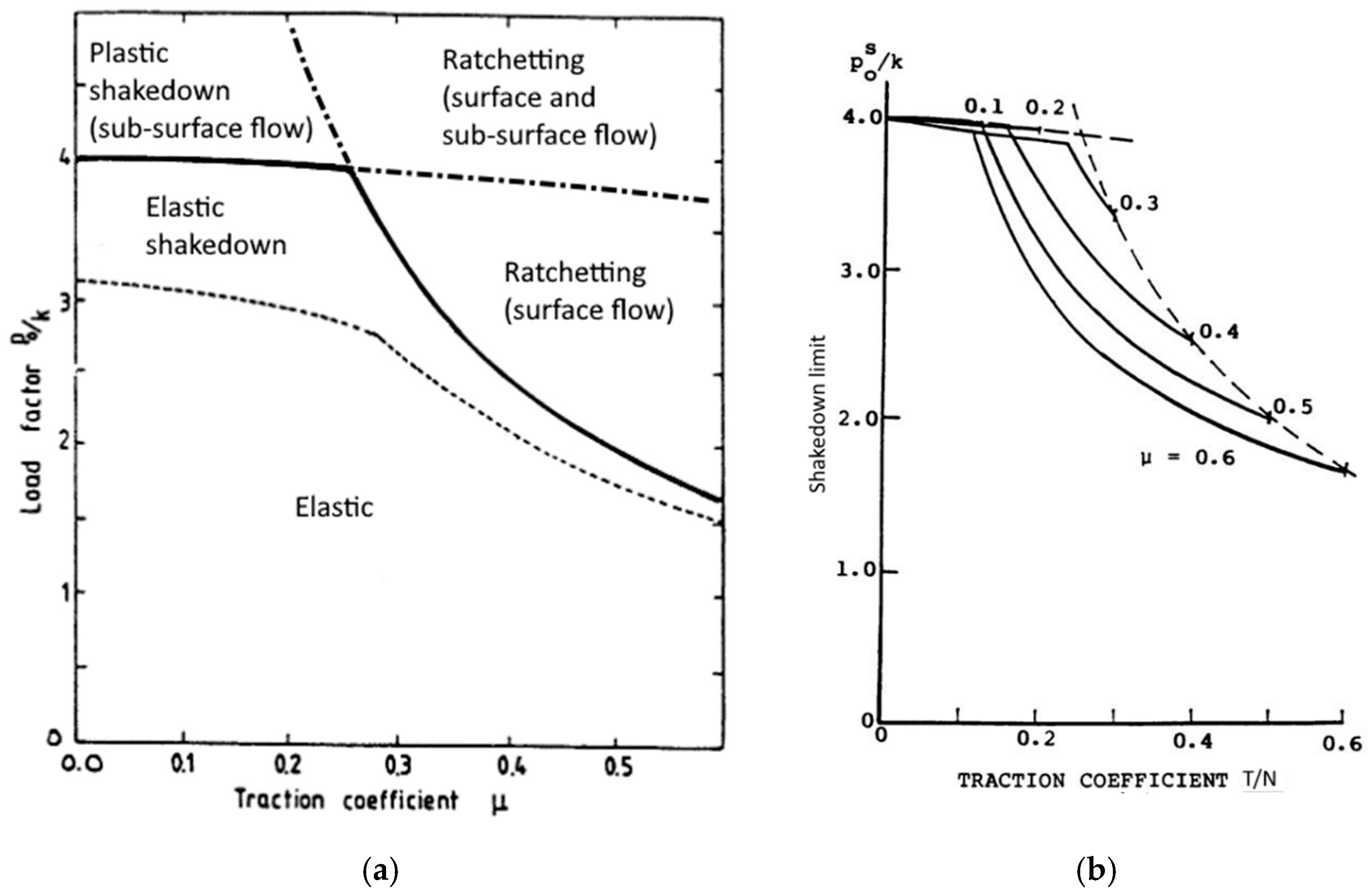
Due to the strain hardening behavior of the material, the shakedown limit is nearly constant up to a critical coefficient of friction μc = 0.25. This critical value diminishes in partial slip conditions, as shown in Figure 5b, which is the typical situation for the wheel/contact. For values higher than μc the plastic flow shifts from sub-surface to surface with a combined surface and sub-surface damage for high values of both traction coefficient and contact pressure.
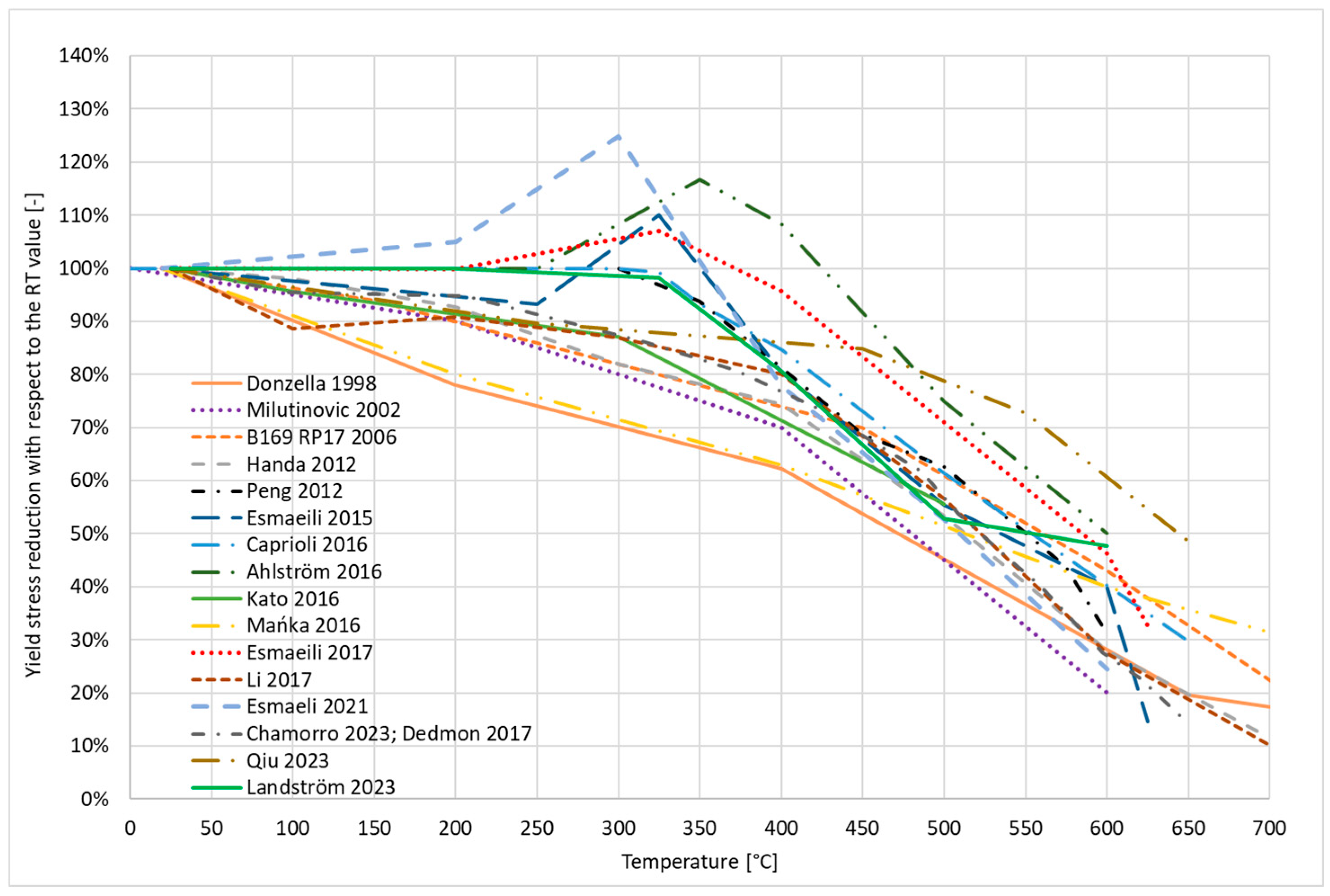
For ER7, which is the most common wheel material, according to standard EN 13262 [23], σy = 520 MPa and therefore k = 300 MPa at room temperature. However, the yield stress of steel for wheels markedly decreases above 400 °C (Figure 6) as found after a specific literature review [24,25,26,27,28,29,30,31,32,33,34,35,36,37,38,39,40].
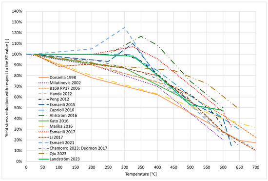
Figure 6.
Reduction in yield stress from values at room temperature as found in [24,25,26,27,28,29,30,31,32,33,34,35,36,37,38,39,40].
These results are taken from studies conducted over a long period of time (1998–2023) and the test conditions were not always the same, as some testing parameters, such as strain rate, multiaxiality, load direction (tension or compression), holding time at temperature, and type of specimen, may influence the results. While a perfect agreement cannot always be found, it is nevertheless evident that mechanical properties degrade with temperature.
Up to 300 °C the strength reduction is relatively low (below 20%), except for Donzella [29] and Mańka [39]. In some works, an increase in yield strength around 300 °C is reported, explained by Teimourimanesh [22] and Esmaeli [26] with the phenomenon of dynamic strain aging (DSA). Then, above 400 °C all the authors reported a relevant decrease in the yield strength with a similar trend, and at 600 °C an average reduction of 60% is found.
The knowledge of the actual temperature of the wheel tread is critical for the validation of the prediction of the thermal behavior of the wheel–brake block pair and to correctly estimate the thermomechanical damage of the wheel.
4. Measurement of Actual Wheel Tread Temperature
4.1. Small-Scale and Full-Scale Temperature Measurement
Measuring with sufficient accuracy the temperature of the wheel tread during braking is challenging. Both contact and contactless measurements show advantages and drawbacks, as will be seen later. Measurements are certainly easier when performed in a stationary environment, i.e., on a test bench used either for homologation of brake components or designed for purpose in a research laboratory.
Small-scale test rigs may be used to evaluate the wear behavior of materials [41,42], but they are not adequate to properly investigate the full-scale temperature distribution, as the scaling factors for mechanical, thermal, and fluid dynamics properties do not provide sufficient reliability of the measurements.
4.2. Temperatures Reached During In-Service Tests
Measuring the in-service wheel temperature is preferable, as the real thermal and mechanical conditions can be observed, including the real wheel–rail contact and the related rail chilling effect. These tests require large amounts of time and money, as extensive measuring campaigns with expensive and delicate instrumentation are not easily manageable on freight wagons.
A literature review of in-service wheel temperature measurements [40,41,42,43,44,45,46] is summarized in Table 2. The various authors concluded the following:
- Landstrom [43] measured mean wheel rim temperatures of passing wagons with a thermal camera placed wayside (8 m from the track), finding most of the wheels around 150 °C with maxima around 240 °C. A high-speed mid-wave infrared (3–5 μm) thermal camera was used by the authors for both field tests and full-scale bench tests described in the next paragraph;
- Cummings [44] performed indirect temperature measurements correlating in-service braking power (estimated from vehicle speed and pressure reduction in the brake pipe) and test rig measurements, finding wheel temperatures below 93 °C. Also, measurements made with wayside wheel temperature detectors showed temperature values below 100 °C;
- Walia [45] carried out field tests on a commuter train, measuring the temperature with sliding thermocouples on the wheel tread and embedded thermocouples on brake blocks. Low temperatures were reached: 40 °C on a motor bogie with electrodynamic braking and cast-iron blocks and 110 °C on a trailer bogie with organic blocks. The results were then used to calibrate a numerical model;
- With the same instrumentation, a maximum temperature of 150 °C was measured by Teimourimanesh [46] on tread-braked wheels of a metro train with composite blocks. Higher values were measured by Vernersson [47] at the Velim test track, applying an average braking power of 50 kW for about 30 min, reaching about 500 °C on the wheel tread. This test aimed to simulate the Gotthard descent with a continuous application of 50 kW for 45 min and an average speed of 60 km/h [2]. Lower values (about 260 °C) were obtained during in-service field tests on the coal line;
- Orringer [48] performed speed reduction and stop braking to reproduce service conditions, measuring the temperature with embedded thermocouples installed below the wheel tread and recording up to 538 °C;
- Vignoli [49] performed drag braking tests on a 21% mean slope in several working conditions, including the presence of the electrodynamic braking of locomotives. Temperatures up to 400 °C were recorded with dynamic braking from two locomotives, between 500 °C and 600 °C with dynamic braking from only one locomotive, and up to 670 °C without any dynamic braking.
Table 2.
Summary of the literature review on in-service temperature measurements.
Table 2.
Summary of the literature review on in-service temperature measurements.
| Author | Vehicle | Brake Blocks | Brake Maneuver | Wheel Temperature | Measurement |
|---|---|---|---|---|---|
| Landstrom 2025 [43] | Freight train | Not specified | Drag braking (about 30 kW for 30 min) | 240 °C | Wayside thermal camera |
| Cummings 2023 [44] | Freight train | Not specified | Braking maneuvers with 5–45 kW for 0.5–5 min | 100 °C | Indirect and wayside hot-wheel detector |
| Walia 2019 [45] | Commuter train | Cast iron and composite (organic) | Repetitive stop braking | 40 °C (cast iron) 100 °C (organic) | Sliding thermocouples |
| Teimourimanesh 2014 [46] | Metro train | Composite (organic) | Repetitive stop braking | 150 °C | Sliding thermocouples |
| Vernersson 2007 [47] | Freight train on Velim test track | Composite | Drag braking (about 50 kW for 30 min) | 500 °C | Sliding thermocouples |
| Freight train | Drag braking (about 10 kW for 20 min) | 250 °C | Sliding thermocouples | ||
| Orringer 1995 [48] | Commuter train | Not specified | Repetitive speed reduction and stop braking | 538 °C | Embedded thermocouples (2.5 mm below the tread) |
| Vignoli 1995 [49] | Freight train | Not specified | Drag braking (about 25 kW for 30 min) | 670 °C | On board and wayside hot-wheel detector |
4.3. Temperatures Reached During Braking on Bench Tests
Due to the difficulties of performing field tests, more contributions to full-scale bench tests were found in the literature. Braking parameters can be easily controlled, i.e., braking force, wheel speed, and air cooling, and several tests can be performed, including tests for wheel and block homologation according to [2,10].
Full scale tests on test benches can be found in refs. [24,25,26,27,28,29,43,50,51,52,53,54,55,56,57], from which the authors (Table 3) reached the following conclusions:
- Landstrom performed full-scale bench tests [43,50,51] measuring temperatures with both sliding thermocouples on the tread and a high-speed mid-wave infrared (3–5 μm) thermal camera placed laterally and using a stainless steel mirror to measure the wheel tread temperature, showing the presence of so-called “hot spots” around the circumference of the wheel tread. The emissivity was estimated by the authors comparing the thermal camera results with the sliding thermocouples readings, but the value is not given in [43]. Painting on the external side of the wheel was applied in [50], while a general emissivity value for oxidized steel (in the range ε = 0.4–0.6) was applied in [51]. The results from drag braking tests with 30 and 50 kW applied for 45 and 30 min showed that tread temperatures over 600 °C are reached, but hot spot temperatures can be up to 200 °C higher than the global tread temperature;
- Hot spots with temperatures exceeding 500 °C were also measured by Cookson [52] using thermal images (no information about thermal camera characteristics) even if the average temperature of the wheel tread measured by sliding thermocouples was in the order of 350 °C. Hot spots appear early when the wheel surface is still globally colder, and relevant hardness reductions (from 350 HB to 230 HB) were measured at these positions after testing;
- Chamorro [24] performed two low-power (about 10 kW) drag brakings of 30 min each, reaching only 150 °C, and then 3D finite element analysis was performed to evaluate abnormal braking load (200% and 300% over the normal service braking). Temperatures around 500 °C were found only for the 300% case;
- Yevtushenko [53] performed several stop braking maneuvers from 80 km/h to calibrate and compare two different FE models (2D axisymmetric and 3D) with two different organic composite brake shoes. Temperatures up to 160 °C were measured with embedded thermocouples placed 5 mm below the wheel tread;
- Handa [54] developed a tread-wear model of the wheel in function of the tread temperature, combining full-scale stop braking, drag braking, and finite element simulations, reaching maximum tread temperatures (simulated) of 400 °C;
- Li [25] used the results of an emergency braking test to calibrate a 3D finite element thermal model that combined with a longitudinal dynamic analysis. A wheel–rail 3D finite element model was used to evaluate the crack initiation time. The maximum temperature measured with the thermal camera during the emergency braking test was 450 °C. No information is given about the infrared thermometer used;
- Wasilewski [16] measured the friction properties of two organic materials on both small-scale and full-scale tests. Stop braking and drag braking were applied on the full-scale bench, monitoring the tread temperatures with three thermocouples placed 2 mm below the wheel surface. Values up to 325 °C were reached for a drag braking of 45 min, applying a power of about 19 kW;
- Several stop braking tests were conducted by Esmaeili [26] and Caprioli [27], measuring the temperature with both embedded thermocouples placed at 10 mm below the tread and with a thermal camera (ε = 1) capturing the contact surface. Embedded thermocouples reached about 300 °C, while surface temperatures measured by thermal camera were up to 500 °C. Thermoelastic instability (TEI) that forms hot bands along the circumference was shown and reproduced by a finite element analysis reaching a maximum temperature of 500 °C for one band 50 mm wide, while about 350 °C was obtained with one band 80 mm wide, i.e., with nominal conditions;
- Similar tests and results are described by Ikeuchi [55];
- Stop braking maneuvers were also applied by Handa [28], measuring temperatures with embedded thermocouples installed 10 mm below the tread surface to calibrate a numerical model by which the full temperature distribution was calculated. Tread temperatures reached 320 °C with nominal tread-block contact, i.e., 80 mm wide, and 570 °C with half-width contact. A set of 130 braking cycles was performed by Handa [56] to generate surface cracks. The wheel temperature was measured only 10 mm beneath the surface, reaching 200 °C at each braking cycle;
- Vernersson [57] performed several drag braking tests with different combinations of block material (cast iron, organic, and sintered) and configurations (1Bg, 1Bgu, 2Bg, and 2Bgu), speed (50, 75, and 100 km/h), and brake power (30, 40, and 50 kW). Temperature was measured with a long-wave infrared (8–14 μm) thermal camera placed laterally to the bench to capture both the wheel and the blocks, which were painted black. Different emissivity values were used due to the different measuring conditions: ε = 1 for the painted blocks (painted, rough surface), ε = 0.95 for the painted wheel (painted, smooth surface), and ε = 0.7 for the wheel tread (unpainted, oxidized). Due to the position of the thermal camera, results are related to one side of the wheel, and only two positions are given (middle of the wheel rim and transition between wheel web and wheel rim). For brake blocks, the mean temperature is also given. A summary of the results for all materials and 2Bgu configuration is given in Table 4. The experimental data were then used to calibrate a numerical model and evaluate the heat partitioning between the wheel and the block;
Table 4. Summary of the temperature results from Vernersson [57].
- Model calibration using full-scale tests is shown also by Donzella [29], reproducing a series of brake cycles with actual parameters from the service (speed and braking power). Tread temperature up to 350 °C was measured with sliding thermocouples.
Table 3.
Summary of the literature review about full scale bench tests temperature measurements.
Table 3.
Summary of the literature review about full scale bench tests temperature measurements.
| Author | Counter Roller | Brake Blocks | Brake Maneuver | Wheel Temperature | Measurement |
|---|---|---|---|---|---|
| Landstrom 2025 [43] Landstrom 2024 [50] Landstrom 2023 [51] | No | Composite (organic) | Drag braking (30 kW for 45 min and 50 kW for 30 min) | 680 °C with hot spots | Sliding thermocouples and thermal camera |
| Cookson 2023 [52] | No | Not specified | Drag braking (32 kW) | 350 °C with hot spots | Sliding thermocouples and thermal camera |
| Chamorro 2023 [24] | No | Not specified | Drag braking (about 10 kW for 30 min) | 150 °C | Sliding thermocouples |
| Yevtushenko 2022 [53] | No | Composite (organic) | Repetitive stop braking from 80 km/h | 160 °C | Embedded thermocouples (5 mm below the tread) |
| Handa 2020 [54] | Yes | Composite (sintered) | Repetitive hold braking at 60 km/h and stop braking from 95 km/h | 200 °C (stop braking) 300 °C (drag braking) | Embedded thermocouples (10 mm below the tread) |
| Li 2017 [25] | No | Composite (sintered) | Emergency braking from 120 km/h | 450 °C | Infrared thermometer |
| Wasilewski 2017 [16] | No | Composite (organic) | Drag braking (about 19 kW for 45 min) Stop braking from 90 km/h | 325 °C (drag braking) 196 °C (stop braking) | Embedded thermocouples (2 mm below the tread) |
| Esmaeli [26] 2017 Caprioli [27] 2016 Ikeuchi [55] 2016 | Yes | Composite (organic and sintered) | Repetitive stop braking from 160 km/h | 300 °C (embedded thermocouple) 500 °C (thermal camera) | Embedded thermocouples (10 mm below the tread) and thermal camera |
| Handa [28] 2012 Handa [56] 2010 | Yes | Composite (sintered) | Repetitive stop braking from 130 km/h | 150 °C 200 °C | Embedded thermocouples (10 mm below the tread) |
| Vernersson [57] 2007 | No | Cat iron and composite (organic and sintered) | Drag braking (30, 40, 50 kW for 45, 37.5, 30 min) | 380 °C (organic) 340 °C (cast iron) 310 °C (sintered) | Thermal camera (side of the wheel) |
| Donzella [29] 1998 | No | Not specified | Repetitive stop braking | 350 °C | Sliding thermocouples |
4.4. Effect of Wheel–Rail Contact and Limitations of the Available Data
Forces exchanged at the wheel–rail contact are a crucial factor in wheel damage, and the rail presence affects wheel tread material behavior in two ways: as contact pressure reaches over 1000 MPa, the effects of forces at the wheel–rail contact are enhanced because of the thermal softening of the wheel material, while the temperature at the contact is affected by the rail chill effect.
According to the review of full-scale tests described in the previous chapter, only one test rig has a counter roller, which is mentioned in several papers [26,27,28,54,55,56]. The counter roller simulates the presence of the rail; it has a diameter of 1 m and a crown head radius of 600 mm, trying to reproduce the wheel–rail Hertzian contact pressure even if lower vertical loads (30 or 60 kN) are used. However, the cooling effect cannot be correctly reproduced by a limited-diameter counter roller because of its finite dimensions when compared to an “infinite” cold rail.
Therefore, the rail chill effect cannot be properly studied on test rigs, and it cannot be easily quantified during in-service tests, as the measuring methods used until today are not able to record the actual wheel surface temperature. Rail chill effect was studied by few authors only by means of FE models [20,47,58,59,60,61] in terms of percentage of braking power absorbed by the rail and in terms of maximum wheel temperature:
- Vernersson [58] simulated a drag at 30 kW for 30 min by a 2D axisymmetric model, showing a rail heat absorption of 27% and 29% for cast iron and composite brake blocks, respectively;
- Vernersson [47] found lower values (22%) after tests and model calibration;
- Teimourimanesh [59] found a heat percentage flowing in the rail of about 20% for a 2D circumferential model, while from 21 to 27% for a 2D axisymmetric model depending on the axial position of the wheel–rail contact;
- Vernersson [20] found that rail chill generates a 15% wheel temperature change after 30 repetitive stop braking maneuvers;
- Peng [60] showed that both stop and drag braking have a similar influence (about 10%) on the maximum wheel tread temperature: for stop braking, a reduction of 22 °C (from 207 to 185 °C), while for drag braking, a reduction of 62 °C (from 632 to 570 °C);
- Teimourimanesh [61] estimated a cooling because of rail chill of about 100 °C for drag braking applied on new (from 500 to 400 °C, i.e., 20% difference) and worn (from 600 to 500 °C, i.e., 17% difference) wheels of both a metro vehicle and a freight wagon.
Generally, all the reviewed papers approach the tread braking problem in different ways, with relevant differences between full-scale tests performed in very stressful and uncommon braking situations and actual in-service conditions.
It is worth noting that constant power drag braking tests often performed on full-scale test rigs represent an unrealistic braking condition, as the average speed in steep tracks is usually maintained with a speed modulation of about ±20 km/h, alternating brake application and release with a typical sawtooth trend. Moreover, the efficient use of the electric braking capacity of modern locomotives helps to reduce the thermal stress introduced into the wheel.
These actions have been historically successfully applied in combination with cast iron brake blocks, but they seem not to be sufficient anymore to guarantee the same level of safety during train operations with the extensive adoption of composite brake blocks.
Recent research shows uncertainties and the limitations related to testing and measurement methods, making the data available not totally convincing about their comprehensive validity to fully understand the current tread braking issues. It was observed that maximum temperature values are relatively dispersed and there is no consensus about them.
This is even more relevant for tests in service due to the intrinsic difficulty of keeping all the measuring parameters under control. It is evident that neither sliding thermocouples (too delicate) nor thermal cameras (too expensive and not sufficiently rugged to be permanently installed on a freight wagon) can be used as reliable temperature monitoring devices, while embedded thermocouples cannot be used for obvious safety reasons.
The difficulties related to correctly performing in-service measurement of the maximum wheel tread temperatures were already shown in the report B64 Rp10 [1]. Here the use of a spot pyrometer with specific characteristics in terms of temperature and wavelength ranges was described, but to the authors’ knowledge, such a solution has never been developed.
5. Thermal Damages of Railway Wheels
5.1. Troubles Occurred in the Last Years and the Regulatory Framework
Freight wagon wheels showed in recent years a higher proneness to damages and failures. As all other boundary conditions remained unchanged, this can only be related to the extensive use of composite brake blocks instead of cast iron blocks.
Between 2016 and 2017, several derailments occurred in Europe due to wheels broken by cracks starting from either the wheel web (BA314 wheel) or the wheel tread (BA004 wheel) [62]. Since these clusters of events, some long-term mitigation measures were adopted, including the following:
- Design modification of the BA314 wheel to reduce stresses on the wheel web;
- BA004 wheels are no longer considered thermostable wheels;
- Additional measures to identify thermal overload of wheels;
- Amendments to the vehicle’s inspection procedures inside the General Contract of Use (GCU) [63].
In 2023 a major derailment occurred at the Gotthard Base Tunnel [64] due to fatigue cracks starting from the tread of a wheel, BA390, similarly to BA004 broken wheels, and further recommendations, such as the increase in the minimum in-service wheel diameter, were given to reduce the derailment risks [65].
While cast iron brake blocks melt, generating sparks during braking, dissipating a large amount of energy and “protecting” the system, organic blocks tend to burn, emitting flames. Several fires originated by burning LL organic blocks occurred in recent years [66]. Additionally, loss of braking capacity at very low temperatures was recognized as the main cause of several accidents in Sweden [67].
In the next paragraphs, a review of wheel tread damage classification documents is described. The goal of this review is to provide a list of references that allow RUs to take the proper actions when some damages are apparent on the tread surface.
The regulation used in Europe to establish the safety and service conditions between RUs and the keeper is the aforementioned GCU. The keeper may use ECM (Entity in Charge of Maintenance) companies that become responsible for the maintenance of wagons. During service, an enterprise may refuse (by “labelling” the wagon) and withdraw from service a wagon (typically at national borders) if issues related to safety are found during the inspection. Wheel inspection is part of the enterprise personnel duty, and tread damage is a potential reason of wagon withdrawal.
5.2. Survey on the Classification of Wheel Tread Damages
Defects on the wheel tread are manifold and may be caused by different phenomena. In addition to the GCU, other references can be applied to passenger and freight to recognize and classify the cause and the severity of wheel tread damages, such as:
- EN 15313:2016, Railway applications—In-service wheelset operation requirements—In-service and off-vehicle wheelset maintenance [68];
- R. Deuce, Wheel Tread Damage: An Elementary Guide [69];
- B169/DT405, Catalogue of defects on wheels/axles/wheelsets [70];
- S. Cantini, S. Cervello, R. Gallo, Handbook of Wheelset Service Faults [71].
Compared to these documents, the catalog about wheel tread irregularities given by the GCU is limited to the information and the actions shown in Table 5. The GCU lacks information about the description and the appearance of the defects affecting wheel tread, while more details can be found in the other documents.
Table 5.
Wheel tread irregularities as described in the GCU. * = for wheel diameter greater than 840 mm.
Table 6 gives more information about the most common wheel tread damages according to the other references. The main difference is related to cracks growing on the wheel tread. GCU considers only isolated transverse cracks (see GCU code 1.3.6), while actions for cracks appearing along the circumference are not defined.
Table 6.
Description of wheel tread defects according to references other than the GCU.
The GCU permits “superficial thermal lattice-type cracking”, named toad skin, which is not referenced in any other documents, and further information for its identification is not given. On the other hand, surface cracks regularly distributed along the tread, such as rolling contact fatigue (RCF) or crazing, are relevant for the other documents. RCF arises from continuous fatigue loading at the wheel–rail contact that leads to exceeding the elastic limit of the material, inducing ratchetting and therefore an incremental plastic deformation and a damage accumulation. Initially, it appears as a series of cracks parallel to each other, characterized by a certain angle with respect to the wheel axes as it is generated by the combination of longitudinal and lateral load [72].
In addition, RCF may appear in different positions of the wheel tread, as the lateral displacement of the wheelset changes depending on the track geometry and the vehicle’s running behavior. On a curved track the wheelset moves laterally, and RCF occurs on the external part of the inner wheel (RCF1) and near the flange of the outer wheel (RCF2). RCF1 and RCF2 may appear on the same wheel as shown in Figure 7a, while on a straight track the wheelset is more centered and RCF occurs on the nominal wheel diameter (RCF3), as shown in Figure 7b.
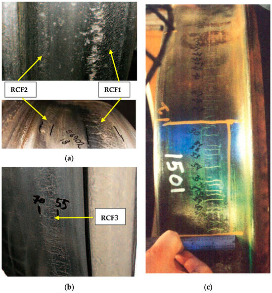
Figure 7.
(a) Examples of RCF1 and RCF2 appearance on the same wheel [69,72]; (b) RCF3 on the nominal wheel diameter [66]; and (c) regular pattern of thermal crazing [73].
Crazing describes a pattern of cracks caused by the combination of thermal stresses and tangential ratcheting resulting from wheel–rail contact. It occurs as a series of thin cracks close to each other and in various directions (called “mosaic” cracks) or as a series of tangential cracks parallel to each other, equidistant. An example is shown in Figure 7c.
Both these defects can generate spalling, i.e., the process of material loss from the contact zone caused by the creation of martensite and crack propagation, while crazing may degenerate to thermal cracks that propagate laterally and radially in the wheel rim and then in the wheel web, causing a complete wheel failure.
5.3. The Appearance of a New Defect
As the only legal document about liability regarding wagon safety inspection procedures is the GCU, RUs may have no sufficient technical support to decide how a wagon should be treated when wheel tread damage is detected.
These difficulties are now more relevant due to the increase in issues related to the thermal properties of composite brake blocks. Wheels structural integrity is a major task to be addressed, and RU attention during inspections has become more important than ever, especially in cases not clearly defined by GCU.
The authors were contacted by an RU to analyze several cases of wheel tread damage that caused controversial discussions between the RU, the wagon keeper, and the ECM.
The authors analyzed about 400 photographs of wheels potentially affected by defects taken during inspection of in-service wagons. The analysis showed that not all the defects were classifiable according to the catalogs described in the previous chapter.
After a visual analysis of these pictures, the authors were able to classify as known defects only part of them (wheel flats (28%) and crazing (11%)) while the other 55% was identified as a new type of defect. It appears as a concentrated spalling in correspondence with the tread datum circumference (the nominal rolling circle of the wheel at 70 mm from the inner side of the wheel) where the wheel touches the rail in straight track. This defect seems to be equally distributed all along the wheel circumference, depicting a continuous development during the wheel rolling.
Even if broadly classifiable as RCF, this new defect appears different from its standard forms due to the absence of the typical pattern of close and parallel cracks along the circumference. On the other hand, spalling or shelling are usually related to limited portions of the wheel surface, while crazing appears as longer cracks equidistant and parallel to each other with zero angle with respect to the wheelset axis.
Therefore, it was supposed that the new defect is linked to RCF induced by the high mechanical loads proper of a loaded wagon in the presence of high temperatures generated during braking. Due to these characteristics the defect was named “thermally induced tread datum RCF” or “THRING” for short.
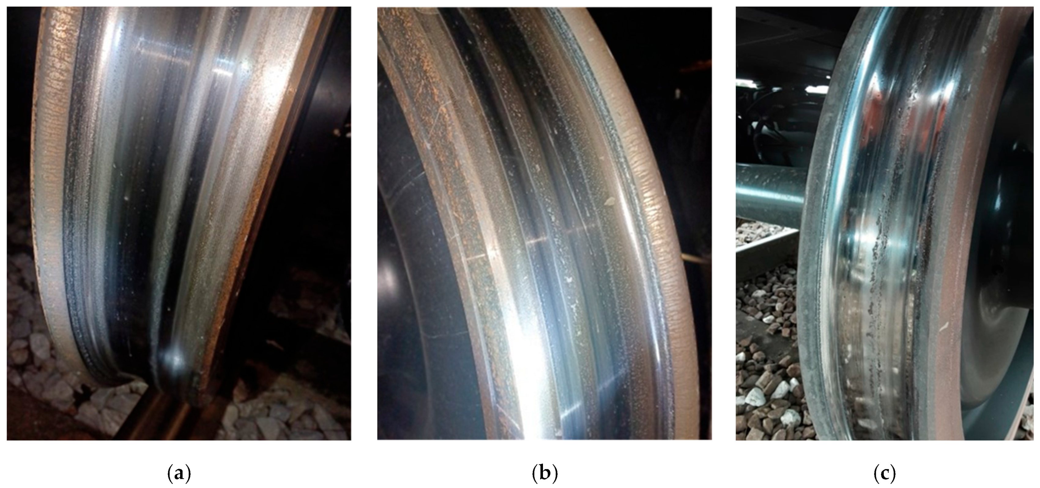
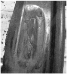
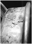
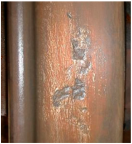
The new defect initially appears as a clearly visible circumferential ring of color and roughness different from the rest of the wheel tread. No material is missing, and at this stage it was classified as low severity. Then the wheel material starts to detach only superficially and a medium severity may be attributed. Finally, considerable material detachment is observed with cavities, i.e., spalling, extended to the whole wheel circumference. In this case a high severity class is allotted. Examples of this evolution and classification are given in Figure 8.
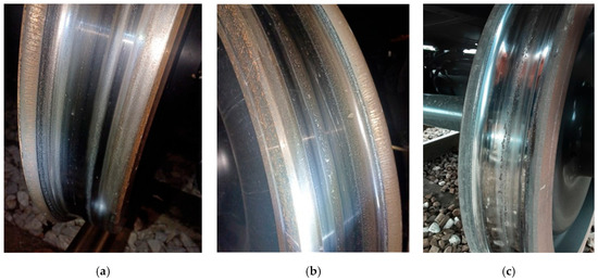
Figure 8.
Example of THRING in three levels of severity. From left to right: low severity (a), medium severity (b), and high severity (c).
The analysis of the available photographs (Figure 9) resulted, as said above, in an extensive presence (55%) of THRING defects, most of which (54%) can be classified as medium severity and the rest as low severity (21%) and high severity (25%). A clear correlation between THRING and the brake block type (K or LL) was not found.
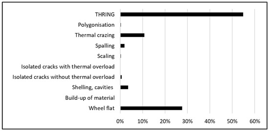
Figure 9.
Results from the analysis of the available pictures from in-service wagon inspections.
An extended analysis of the new defect considering actual in-service temperature measurements and FE damage analysis will be discussed in a future paper.
6. Conclusions
This paper has reviewed the literature on tread braking of freight wagons, starting from the original cast iron used for brake blocks to the recent uniform adoption of composite (sintered or organic) K and LL blocks. Sources for the classification of wheel tread damages were also discussed and critically compared. The review of technical documents related to wheel tread damages may help Railway Undertakings to make decisions during wagon inspection procedures.
Actions such as sawtooth braking and the use of electrodynamic braking, which proved to be effective with cast iron brake blocks, seem to be not sufficient to guarantee the same level of safety during freight train operations. The lower thermal conductivity of the composite brake block was deemed to be responsible for a higher thermal stress of the tread that strongly reduces the material mechanical properties and originates a greater number of wheel issues and failures. Moreover, a new type of defect that was not previously described, consisting of a ring of damaged material positioned in the tread datum zone, was found during the analysis of pictures from in-service wagon inspections.
Temperature measurements are critical to properly estimate steel damage. The existing literature showed that no comprehensive data are available due to uncertainties and limitations of both in-service and test rig measurements, while the rail chill effect is currently estimated only by simulations.
The need for a rugged, contactless, and low-cost device to be applied for long-term in-service wheel tread temperature monitoring, allowing the collection of a proper set of data to be used as input to analyze the wheel-damaging process, is clearly missing in the current state-of-the-art.
Pyrometers are more rugged and relatively inexpensive compared to thermal cameras, and they can be implemented in a stand-alone monitoring system. The description of the development, calibration, and application of a measuring system based on a moving spot pyrometer will be shown in a future specific paper.
Author Contributions
Conceptualization, A.B.; methodology, G.M. and A.B.; investigation, G.M.; data curation, G.M. and A.B.; writing—original draft preparation, G.M.; writing—review and editing, G.M. and A.B. All authors have read and agreed to the published version of the manuscript.
Funding
The authors received no financial support for the research, authorship, and/or publication of this article.
Data Availability Statement
The data supporting the conclusions of this article will be made available by the authors on request.
Acknowledgments
The technical support of InRail SpA, an Italian Railway Undertaking that provided the analyzed photographs, is gratefully acknowledged.
Conflicts of Interest
The authors declared no potential conflicts of interest with respect to the research, authorship, and/or publication of this article.
References
- ORE B64 Committee. Semelles de Frein in Matériaux Composites, Rp1~Rp10; Office de Recherches et d’Essais (ORE) de l’Union Internationale des Chemins de fer (UIC): Utrecht, The Netherlands, 1965~1971. [Google Scholar]
- EN 13979-1:2023; Railway Applications-Wheelsets and Bogies-Monobloc Wheels-Technical Approval Procedure-Part 1: Forged and Rolled Wheels. European Standards: Brussels, Belgium, 2023.
- UIC 510-5; Technical Approval of Monobloc Wheels—Application Document for Standard EN 13979-1. Union Internationale des Chemins de fer (UIC): Paris, France, 2007.
- ERRI report B 169/RP 3; Thermal Limits of Wheels and Brake Shoes. Research of Fracture Threshold. European Rail Research Institute: Utrecht, The Netherlands, 1991.
- ERRI report B 169/RP 9; Definition of Technical Requirements of Wheels. Mechanical Design. Fatigue Behaviour. European Rail Research Institute: Utrecht, The Netherlands, 1997.
- ERRI report B 169/RP 10; Definition of Technical Requirements of Wheels. Mechanical Design Assessment. European Rail Research Institute: Utrecht, The Netherlands, 1999.
- ERRI report B 169/RP 11; Definition of Technical Requirements of Wheels. Thermomechanical Design. Behaviour to Radial Fracture. European Rail Research Institute: Utrecht, The Netherlands, 1998.
- UIC 510-2; Trailing Stock: Wheels and Wheelsets. Conditions Concerning the Use of Wheels of Various Diameters. Union Internationale des Chemins de fer (UIC): Paris, France, 2004.
- Joint Sector Group. Final Report on the Results of the Joint Sector Group Activities Linked to the Action Plan Defined Under the Task Force Freight Wagon Maintenance. 17 December 2012. Available online: https://www.jsgrail.eu/ (accessed on 12 February 2025).
- UIC 541-4; Brakes-Composite Brake Blocks-General Conditions for Certification and Use. Union Internationale des Chemins de fer (UIC): Paris, France, 2020.
- 2006/66/EC: European Commission, Commission Decision of 23 December 2005 Concerning the Technical Specification for Interoperability Relating to the Subsystem ‘Rolling Stock Noise’ of the Trans-European Conventional Rail System; European Commission: Brussels, Belgium, 2006.
- UIC. Real Noise Reduction of Freight Wagon Retrofitting; Union Internationale des Chemins de fer (UIC): Paris, France, 2013; Available online: https://uic.org/IMG/pdf/md-af20120302_noise_reduction_by_freight_wagon_retrofitting_synthesis_report_update_18012013.pdf (accessed on 1 July 2025).
- EN 16452:2015+A1:2019; Railway Applications-Braking-Brake Blocks. European Standards: Brussels, Belgium, 2019.
- UIC 832; Technical Specification for the Supply of Brake-Shoes Made from Phosphoric Iron for Tractive and Trailing Stock. Union Internationale des Chemins de fer (UIC): Paris, France, 2004.
- Carpignano, A. Meccanica dei Trasporti Ferroviari e Tecnica Delle Locomotive; Levrotto & Bella: Torino, Italy, 1985. [Google Scholar]
- Wasilewski, P. Experimental study on the effect of formulation modification on the properties of organic composite railway brake shoe. Wear 2017, 390–391, 283–294. [Google Scholar] [CrossRef]
- Vernersson, T.; Ekberg, A.; Lundén, R. Railway freight braking and LL brake blocks. In Proceedings of the XIX International Wheelset Congress (IWC), Venice, Italy, 16–20 June 2019. [Google Scholar]
- EN 15302:2021; Railway applications-Wheel-Rail Contact Geometry Parameters-Definitions and Methods for Evaluation. European Standards: Brussels, Belgium, 2021.
- UIC. Question 5–110 Noise Abatement-Fitting Composite Brake Blocks to Wagons-Usage Guidelines for Composite (LL) Brake Blocks; Union Internationale des Chemins de fer (UIC): Paris, France, 2013; Available online: https://uic.org/IMG/pdf/uic_usage_guidelines_for_composite_brake_blocks_ll_not-updated.pdf (accessed on 1 July 2025).
- Vernersson, T.; Lundén, R. Wear of brake blocks for in-service conditions—Influence of the level of modelling. Wear 2014, 314, 125–131. [Google Scholar] [CrossRef]
- Johnson, K.L. A Graphical Approach to Shakedown in Rolling Contact; Hyde, T.H., Ollerton, E., Eds.; Springer: Dordrecht, The Netherlands, 1990; pp. 263–274. [Google Scholar]
- Teimourimanesh, S.; Vernersson, T.; Lundén, R. Thermal capacity of tread-braked railway wheels. Part 1: Modelling. Proc. Inst. Mech. Eng. Part F J. Rail Rapid Transit 2016, 230, 784–797. [Google Scholar] [CrossRef]
- EN 13262:2004+A2:2011; Railway Applications-Wheelsets and Bogies-Wheels-Product Requirements. European Standards: Brussels, Belgium, 2011.
- Chamorro, R.; Rodrigues, T.B.; Farias, L.; Teixeira, L. Wheel stress simulation analysis during abnormal braking applications in rail wagons. In Proceedings of the 20th International Wheelset Congress (IWC), Chicago, IL, USA, 8–11 May 2023. [Google Scholar]
- Li, L.; Chang, C.Y.; Wang, J.B.; Chen, D. Study on crack initiation life of heavy haul wheel under the coupling action of braking thermal load and rolling contact fatigue. In Proceedings of the 11th International Heavy Haul Association Conference (IHHA 2017), Cape Town, South Africa, 2–6 September 2017. [Google Scholar]
- Esmaeili, A.; Walia, M.S.; Handa, K.; Ikeuchi, K.; Ekh, M.; Vernersson, T.; Ahlström, J. A methodology to predict thermomechanical cracking of railway wheel treads: From experiments to numerical predictions. Int. J. Fatigue 2017, 105, 71–85. [Google Scholar] [CrossRef]
- Caprioli, S.; Vernersson, T.; Handa, K.; Ikeuchi, K. Thermal cracking of railway wheels: Towards experimental validation. Tribol. Int. 2016, 94, 409–420. [Google Scholar] [CrossRef]
- Handa, K.; Morimoto, F. Influence of wheel/rail tangential traction force on thermal cracking of railway wheels. Wear 2012, 289, 112–118. [Google Scholar] [CrossRef]
- Donzella, G.; Scepi, M.; Solazzi, L.; Trombini, F. The effect of block braking on the residual stress state of a solid railway wheel. Proc. Inst. Mech. Eng. Part F J. Rail Rapid Transit 1998, 212, 145–158. [Google Scholar] [CrossRef]
- Peng, D.; Jones, R.; Constable, T. A study into crack growth in a railway wheel under thermal stop brake loading spectrum. Eng. Fail. Anal. 2012, 25, 280–290. [Google Scholar] [CrossRef]
- Landström, E.V.; Steyn, E.; Ahlström, J.; Vernersson, T. Thermomechanical testing and modelling of railway wheel steel. Int. J. Fatigue 2023, 168, 107373. [Google Scholar] [CrossRef]
- Qiu, C.; Tran, L.; Mutton, P.J.; Cookson, J.M. The influence of elevated temperatures on mechanical properties of wheel materials. In Proceedings of the 12th International Heavy Haul Association Conference 2023 (IHHA Rio 2023), Rio de Janeiro, Brazil, 27–31 August 2023. [Google Scholar]
- Dedmon, S.L. Effect of temperature on the performance of railroad wheels. Proc. Inst. Mech. Eng. Part F J. Rail Rapid Transit 2017, 231, 786–793. [Google Scholar] [CrossRef]
- Esmaeili, A.; Ahlström, J.; Ekh, M.; Nikas, D.; Vernersson, T. Modelling of temperature and strain rate dependent behaviour of pearlitic steel in block braked railway wheels. Rail. Eng. Sci. 2021, 29, 362–378. [Google Scholar] [CrossRef]
- Kato, T.; Kato, H.; Makino, T. Effect of elevated temperature on shelling property of railway wheel steel. Wear 2016, 366–367, 359–367. [Google Scholar] [CrossRef]
- Milutinovic, D.; Radosavljevic, A. Thermal Load of Block Braked Solid Wheel on Yugoslav Railways, Computers in Railways VII; Brebbia, C.A., Allan, J., Hill, R.J., Sciutto, G., Sone, S., Eds.; WIT Press: Billerica, MA, USA, 2000. [Google Scholar]
- Caprioli, S.; Vernersson, T.V.; Ekberg, A.; Kabo, E. Thermomechanical cracking of railway wheel treads. In Proceedings of the 10th International Conference on Contact Mechanics of Wheel/Rail Systems (CM2015), Colorado Springs, CO, USA, 30 August 2015. [Google Scholar]
- Ahlström, J.; Kabo, E.; Ekberg, A. Temperature-dependent evolution of the cyclic yield stress of railway wheel steels. Wear 2016, 366–367, 378–382. [Google Scholar] [CrossRef]
- Mańka, A.; Sitarz, M. Effects of a thermal load on the wheel/brake-block subsystem: The thermal conicity of railway wheels. Proc. Inst. Mech. Eng. Part F J. Rail Rapid Transit 2016, 230, 193–205. [Google Scholar] [CrossRef]
- ERRI Report B169/RP17; Definition of Parameters for the Thermomechanical Calculation of Wheels-Correlation Between Calculations and Tests. European Rail Research Institute: Utrecht, The Netherlands, 2006.
- Ghidini, L.; Faccoli, M.; Zani, N.; Petrogalli, C.; Bonometti, S.; Mazzu, A. An innovative small-scale testing procedure to study damage in shoe-braked wheels. Proc. Inst. Mech. Eng. Part F J. Rail Rapid Transit 2024, 238, 414–426. [Google Scholar] [CrossRef]
- Faccoli, M.; Provezza, L.; Petrogalli, C.; Ghidini, A.; Mazzù, A. Effects of full-stops on shoe-braked railway wheel wear damage. Wear 2019, 428–429, 64–75. [Google Scholar] [CrossRef]
- Landström, E.; Vernersson, T.; Lundén, R. Characterisation and evaluation of global uneven heating during railway tread braking–Brake rig testing and field study. Proc. Inst. Mech. Eng. Part F J. Rail Rapid Transit 2025, 239, 258–271. [Google Scholar] [CrossRef]
- Cummings, S.M.; Patil Dumbre, S.S. Effects of braking on wheel wear and tread damage. In Proceedings of the 12th International Heavy Haul Association Conference, Rio de Janeiro, Brazil, 27–31 August 2023. [Google Scholar]
- Walia, M.S.; Vernersson, T.; Lundén, R.; Blennow, F.; Meinel, M. Temperatures and wear at railway tread braking: Field experiments and simulations. Wear 2019, 440–441, 203086. [Google Scholar] [CrossRef]
- Teimourimanesh, S.; Vernersson, T.; Lundén, R.; Blennow, F.; Meinel, M. Tread braking of railway wheels–temperatures generated by a metro train. Proc. Inst. Mech. Eng. Part F J. Rail Rapid Transit 2014, 228, 210–221. [Google Scholar] [CrossRef]
- Vernersson, T.; Lundén, R. Temperatures at railway tread braking. Part 3: Wheel and block temperatures and the influence of rail chill. Proc. Inst. Mech. Eng. Part F J. Rail Rapid Transit 2007, 221, 443–454. [Google Scholar] [CrossRef]
- Orringer, O.; Gray, D.E. Thermal cracking in railroad vehicle wheels subjected to high performance stop braking. Theor. Appl. Fract. Mech. 1995, 23, 55–65. [Google Scholar] [CrossRef]
- Vignoli, M.; Mazzoni, S.; Pampaloni, T. Influenza della frenatura dei treni sulla temperatura delle ruote. La Tec. Prof. 1995, 8, 26–45. [Google Scholar]
- Landström, E.V.; Vernersson, T.; Lundén, R. Analysis and testing of tread braked railway wheel—Effects of hot spots on wheel performance. Int. J. Fatigue 2024, 180, 108116. [Google Scholar] [CrossRef]
- Landström, E.V.; Vernersson, T.; Lundén, R. Improved Finite Element Modelling of Tread Braked Wheel Performance Verified by Brake Rig Tests. In Proceedings of the 20th International Wheelset Congress (IWC), Chicago, IL, USA, 8–11 May 2023. [Google Scholar]
- Cookson, J.; Mutton, P.; Tran, L.; Qui, C.; Saporito, R.; Crew, G. Tread damage due to extreme thermal localization under high braking loads in heavy haul operations. In Proceedings of the 20th International Wheelset Congress (IWC), Chicago, IL, USA, 8–11 May 2023. [Google Scholar]
- Yevtushenko, A.; Kuciej, M.; Grzes, P.; Wasilewski, P. Methodology of estimation of temperature mode in the 2xBgu type railway braking system. Sci. Rep. 2022, 12, 20829. [Google Scholar] [CrossRef]
- Handa, K.; Ikeuchi, K.; Morimoto, F. Temperature-dependent wear of tread-braked railway wheels. Wear 2020, 452–453, 203265. [Google Scholar] [CrossRef]
- Ikeuchi, K.; Handa, K.; Lundén, R.; Vernersson, T. Wheel tread profile evolution for combined block braking and wheel–rail contact: Results from dynamometer experiments. Wear 2016, 366–367, 310–315. [Google Scholar] [CrossRef]
- Handa, K.; Kimura, Y.; Mishima, Y. Surface cracks initiation on carbon steel railway wheels under concurrent load of continuous rolling contact and cyclic frictional heat. Wear 2010, 268, 50–58. [Google Scholar] [CrossRef]
- Vernersson, T. Temperatures at railway tread braking. Part 2: Calibration and numerical examples. Proc. Inst. Mech. Eng. Part F J. Rail Rapid Transit 2007, 221, 429–441. [Google Scholar] [CrossRef]
- Vernersson, T. Temperatures at railway tread braking. Part 1: Modelling. Proc. Inst. Mech. Eng. Part F J. Rail Rapid Transit 2007, 221, 167–182. [Google Scholar] [CrossRef]
- Teimourimanesh, S.; Vernersson, T.; Lundén, R. Modelling of temperatures during railway tread braking: Influence of contact conditions and rail cooling effect. Proc. Inst. Mech. Eng. Part F J. Rail Rapid Transit 2014, 228, 93–109. [Google Scholar] [CrossRef]
- Peng, D.; Jones, R.; Constable, T. An investigation of the influence of rail chill on crack growth in a railway wheel due to braking loads. Eng. Fract. Mech. 2013, 98, 1–14. [Google Scholar] [CrossRef]
- Teimourimanesh, S.; Lundén, R.; Vernersson, T. Braking Capacity of Railway Wheels–State-of-the-art Survey. In Proceedings of the 16th International Wheelset Congress (IWC16), Cape Town, South Africa, 15-17 March 2010. [Google Scholar]
- JNS Procedure. “Broken Wheels”. 28 November 2019. Available online: https://www.era.europa.eu/system/files/2022-11/jns_np_tf_broken_wheels_final_output_en.pdf (accessed on 12 February 2025).
- GCU Bureau. General Contract of Use for Wagons. Available online: https://gcubureau.org/ (accessed on 1 July 2025).
- Swiss Transportation Safety Investigation Board STSB, Interim Report of the Swiss Security Investigation Office SUST About the Derailment of a Freight Train in the Gotthard Base Tunnel. Available online: https://www.sust.admin.ch/inhalte/BS/2023081002_GBT_ZB_i.pdf (accessed on 1 July 2025).
- JNS Procedure. Accident Gotthard Base Tunnel Broken Wheels. 11 July 2024. Available online: https://www.era.europa.eu/system/files/2024-07/JNS%20NP%20Gothard_Final%20report_v2.0.pdf (accessed on 1 July 2025).
- JNS Procedure. Consequences of Unintended Brake Applications with LL Blocks. 29 February 2024. Available online: https://www.era.europa.eu/system/files/2024-03/JNS%20NP%20LL%20brake%20blocks_Final%20report_v2.0.pdf (accessed on 1 July 2025).
- Pelcastre, L.; Weniger, L.-M.; Hardell, J. On the low temperature tribological behaviour of brake block materials for railway applications under dry and icy conditions. Wear 2023, 523, 204764. [Google Scholar] [CrossRef]
- EN15313:2016; Railway Applications-in-Service Wheelset Operation Requirements-in-Service and Off-Vehicle Wheelset Maintenance. European Standards: Brussels, Belgium, 2016.
- Deuce, R. Wheel Tread Damage: An Elementary Guide; Bombardier Transportation GmbH: Netphen, Germany, 2007. [Google Scholar]
- B169/DT405; Catalogue of Defects on Wheels/Axles/Wheelsets. Union Internationale des Chemins de fer (UIC): Paris, France, 2008.
- Cantini, S.; Cervello, S.; Gallo, R. Handbook of Wheelset Service Faults, Lucchini Techno 09a; Lucchini RS: Lovere, Italy, 2016. [Google Scholar]
- Molyneux-Berry, P.; Bevan, A. Wheel surface damage: Relating the position and angle of forces to the observed damage patterns. Veh. Syst. Dyn. 2012, 50 (Suppl. 1), 335–347. [Google Scholar] [CrossRef]
- Federal Railroad Administration. Wheel-Peeling Experiment-Analysis of Commuter Rail Wheel Thermal Cracks; U.S. Department of Transportation, Office of Research & Development: Washington, DC, USA, 1994.


Disclaimer/Publisher’s Note: The statements, opinions and data contained in all publications are solely those of the individual author(s) and contributor(s) and not of MDPI and/or the editor(s). MDPI and/or the editor(s) disclaim responsibility for any injury to people or property resulting from any ideas, methods, instructions or products referred to in the content. |
© 2025 by the authors. Licensee MDPI, Basel, Switzerland. This article is an open access article distributed under the terms and conditions of the Creative Commons Attribution (CC BY) license (https://creativecommons.org/licenses/by/4.0/).