Abstract
This study proposes a novel control framework for semi-active seat suspensions, specifically targeting motion sickness mitigation through precision suppression of vertical vibrations within the 0.1–0.5 Hz frequency range. Firstly, a fractional-order band-stop filter in conjunction with a linear quadratic regulator (LQR) controller under frequency-domain sensitivity constraints (0.1–0.5 Hz) is proposed to achieve frequency-selective vibration attenuation. Secondly, the multi-objective butterfly optimization algorithm (MOBOA) is adopted to optimize the LQR controller’s weighting matrices (Q, R) by balancing conflicting requirements in terms of human body displacement limits, acceleration thresholds, and suspension travel. Finally, experimental validation under concrete pavement excitation and random road profiles demonstrates significant advantages over conventional LQR, i.e., a 41.04% reduction in vertical vibration amplitude and a 55.95% suppression of acceleration peaks within the target frequency band. The combined enhancements offer dual benefits of enhancing ride comfort and motion sickness mitigation in real-world driving scenarios.
1. Introduction
The automotive industry’s ongoing paradigm shift toward intelligent electrification has elevated vibration-induced ride comfort to a critical performance metric in next-generation vehicle design. This imperative is particularly challenged by vertical oscillations within the 0.1–0.5 Hz biodynamic susceptibility band, which directly activates motion sickness pathogenesis through the vestibule–ocular sensory incongruence—a neurophysiological conflict arising from mismatched visual and inertial motion cues. As experimentally validated by Asua et al. [1], this critical frequency range demonstrates a dose-dependent relationship with motion sickness incidence (MSI) through otolith-dominated vestibular afferent pathways, where the otolithic organs’ heightened sensitivity to sub-1 Hz linear accelerations (ISO 2631-1:1997 [2]) generates maladaptive neural integration in the velocity storage mechanism of the central nervous system. Within the human–vehicle vibrational energy transfer chain, commercial vehicle seats constitute the primary vibration transmission interface [3], rendering their low-frequency transmissibility attenuation capability pivotal for anthropometric comfort preservation. Although modern active suspension systems employing skyhook damping strategies achieve partial vibration energy dissipation in the 0.5–5 Hz range [4], their inherent limitations in handling cross-axis dynamic coupling, particularly the pitch-vertical modal interactions characteristic of multi-axle vehicles, reveal the fundamental deficiencies in multi-degree-of-freedom vibration decoupling control architectures.
The current technological landscape of intelligent vehicle suspension systems presents a fundamental dichotomy between active and semi-active configurations, each constrained by intrinsic performance ceilings. Active architectures, employing high-bandwidth hydraulic/piezoelectric actuators for full-state force regulation, confront the dual challenges of high-dimensional nonlinear dynamics and computational intractability. Output feedback technology is the key to solving the problem of unmeasurable states. The mainstream solutions adopt H∞ control, model predictive control (MPC), etc., and combine observers (such as Kalman filters/extended state observers) to fuse sensor data with the system model, ultimately building a control capability equivalent to full-state feedback [5]. Rath et al.’s fourth-order terminal sliding mode control with high-gain observers [6] exemplifies the modeling accuracy paradox; while achieving μ-level state estimation precision, it demonstrates pathological sensitivity to parametric uncertainties. Parallel developments, like Dertimanis et al.’s LQR-UKF synthesis [7], reveal the curse of dimensionality: unscented Kalman filter-based gain adaptation increases the computational complexity per iteration, exceeding the automotive-grade ECU processing budgets. These limitations compound with prohibitively high per-unit costs and energy densities, rendering active systems commercially unviable for mass-market vehicles. Semi-active alternatives employing magnetorheological (MR) dampers present an energy-efficient compromise through Bingham plastic model-based damping modulation. Yao et al.’s frequency response characterization [8] quantified MR dampers’ operational bandwidth limitations while exposing conventional PID controllers’ spectral blindness in the critical sensitivity range (0.1–0.5 Hz) [9]. Conventional LQR designs [10,11] exhibit constrained frequency-domain performance due to their inherent time-domain-oriented weighting matrices, necessitating the incorporation of frequency-domain shaping techniques to achieve meaningful low-frequency vibration attenuation. Nonlinear damping curve control based on improved particle swarm optimization [12] improves algorithm convergence through dynamic inertia coefficients but has been proven ineffective in reducing resonance phenomena within the vestibular sensitive frequency range. The LQR/H∞ hybrid active suspension controller [13] enhances the robustness of the system through a combination control method, but its time-frequency decoupling architecture has inherent limitations. More notably, Yang et al. [14] found that traditional semi-active control produces significant phase deviation under random road conditions (such as impact), further exacerbating the risk of failure in low-frequency vibration control. Road-adaptive preview H∞ control for active suspension systems demonstrates enhanced control precision in comfort improvement [15]; the inherent real-time computational constraints of road recognition algorithms, particularly the excessive computational latency during multi-sensor data fusion processes, fundamentally hinder its practical implementation within automotive-grade electronic control units (ECUs).
Although existing research has made certain progress in the frequency-domain optimization of suspension systems, it still exhibits significant theoretical deficiencies in elucidating the core issue of the physiological dynamic coupling mechanism in vibration control. Compared to the limitations of conventional control strategies, such as H∞ frequency-domain shaping [16] or high-order transfer function optimization [17], this study reveals that current methods demonstrate notable inadequacies in dynamic frequency-band tracking within the vestibular sensitive frequency range, with the control accuracy falling far short of the actual requirements for human physiological perception. Most critically, existing studies have entirely failed to establish a quantitative relationship between the dynamic characteristics of inerter devices and vestibular perception thresholds. For the pivotal dynamic issue of pitch-vertical coupled vibrations—a core contributor to motion sickness—current control strategies still exhibit evident shortcomings in multi-axis coordination performance. Although advanced technologies such as magnetorheological semi-active control have achieved adaptive regulation [18], their design philosophy surprisingly neglects the critical factor of frequency-domain optimization in vestibular sensitive bands. A more fundamental limitation lies in the fact that current research has generally failed to break through the constraints of traditional frequency-domain analysis frameworks. There exists an inherent deficiency in the co-modeling of time-frequency distribution characteristics of vibration energy and the nonlinear features of human perception, which severely restricts the physiological adaptability of control strategies. While integral sliding mode control (ISMC) substantially improves the disturbance rejection capabilities, its intrinsic high-frequency chattering phenomena may accelerate mechanical degradation in suspension actuators. Current LQR sliding mode hybrid controllers demonstrate satisfactory performance metrics, yet the acceleration chattering induced by fixed sliding mode switching thresholds generates fundamental conflicts between the temporal discontinuity characteristics and the low-frequency sensitivity of human vestibular physiology [19,20]. By leveraging the input constraint handling methodology from explicit model predictive control in magnetorheological damper-based semi-active suspensions [21], we can construct a control framework that concurrently achieves frequency-selective performance and temporal stability. Seat suspension systems possess distinctive merits through their inherent multi-degree-of-freedom decoupling characteristics, with the dual-layer multi-DOF automotive seat architecture particularly offering an optimal implementation platform for low-frequency vibration mitigation [22]. Conventional control paradigms employing LQR suffer from inherent full-frequency-band trade-off limitations that constrain their low-frequency vibration attenuation efficacy. Current parameter optimization approaches, including enhanced chaotic butterfly optimization and multi-objective algorithms utilizing chaotic global search mechanisms [23,24,25], remain fundamentally inadequate in addressing the critical frequency-selective performance deficiency. Although the sparrow search algorithm-based BP neural network PID hybrid intelligent control strategy [26] successfully merges computational intelligence with classical control paradigms, its frequency-domain shaping performance demands substantial refinement. While low-bandwidth continuously variable damping systems [27] employing time-invariant LQR control for damping ratio optimization demonstrate notable ride comfort improvements without compromising safety, their static weighting configurations prove insufficient for dynamic suppression requirements in the motion sickness critical 0.1–0.5 Hz frequency range.
To address the aforementioned persistent technical challenges in vibration mitigation, this study develops an innovative semi-active seat suspension system that synergistically integrates band-stop filtration mechanisms with LQR collaborative control. The proposed architecture introduces a dual-mode control strategy featuring frequency-selective attenuation (0.1–0.5 Hz) specifically tailored for motion sickness mitigation, effectively resolving the inherent frequency-domain limitations of conventional suspension systems that deteriorate ride comfort through broadband vibration transmission. The principal contributions of this study are outlined below:
(1) This investigation establishes a frequency-selective control paradigm specifically engineered for the biomechanically critical 0.1–0.5 Hz band corresponding to vestibular-induced motion sickness. The methodology introduces a co-design framework synergistically integrating fractional-order band-stop filtration with LQR optimization, wherein a dynamically adaptive weight matrix is systematically constructed through fractional calculus operators. This bio-inspired coupling mechanism fundamentally redefines the filter-controller interaction by establishing a parametric mapping between the filter’s complex frequency characteristics and the LQR’s temporal regulation laws, thereby overcoming the fundamental performance compromise between spectral selectivity and transient response that plagues conventional vibration control systems. The proposed architecture establishes a novel design paradigm for vehicular comfort enhancement through frequency-aware mechatronic coordination, particularly effective under multi-source vibrational excitations.
(2) To resolve the locally optimal control performance resulting from empirical weight matrix tuning in traditional LQR controllers, the multi-objective butterfly optimization algorithm is adopted to optimize the LQR controller’s weighting matrices (Q, R) by balancing conflicting requirements related to human body displacement limits, acceleration thresholds, and suspension travel under high-frequency disturbances. This approach achieves accelerated convergence toward the Pareto frontier and overcomes the computational inefficiency bottlenecks that plague classical optimization algorithms when addressing multi-objective optimal control problems.
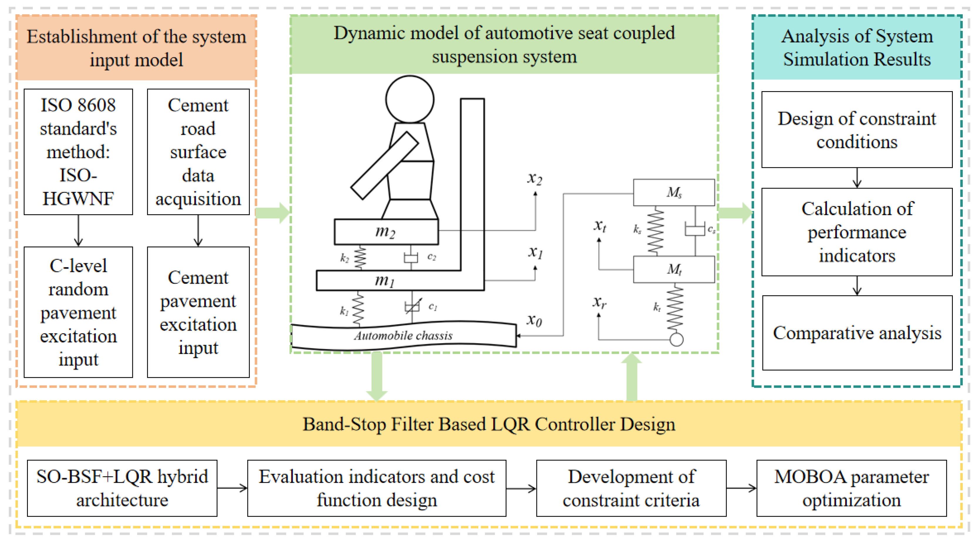
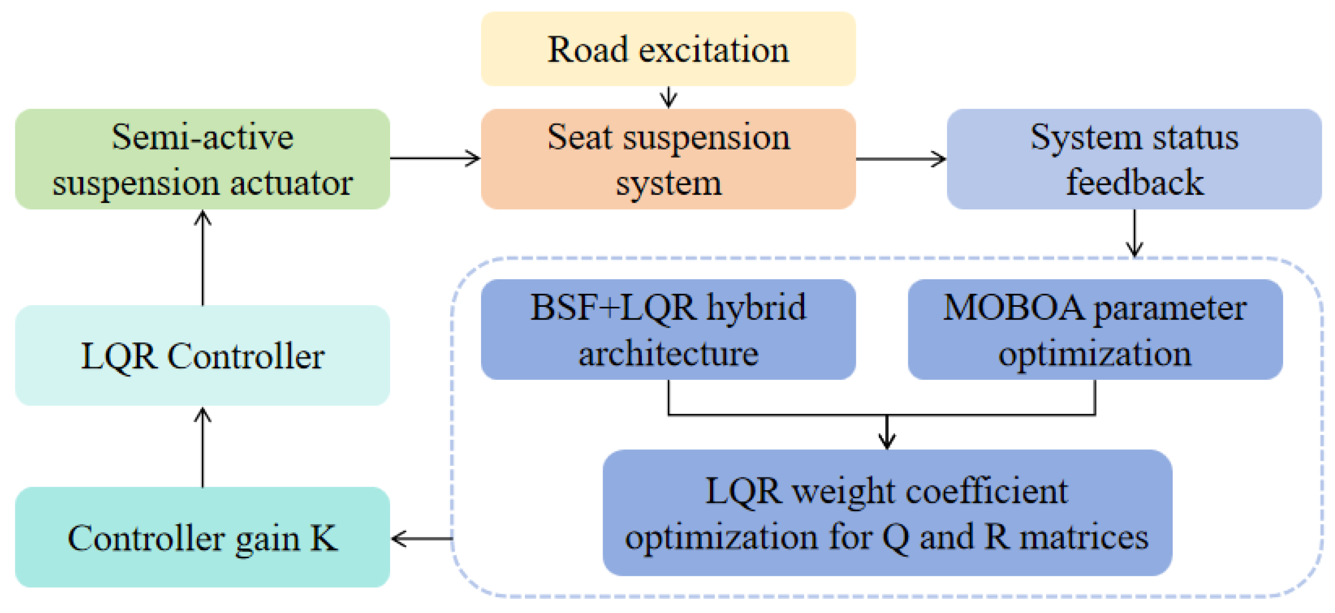
The remainder of this paper is organized as follows: Section 2 establishes the road and seat system model and analyzes the system’s working mechanism. Section 3 presents the design and optimization analysis of a band-stop filter-based LQR controller. Section 4 includes the analysis of simulation and experimental results. Finally, the conclusions are drawn in Section 5. Figure 1 illustrates the detailed workflow of this study.
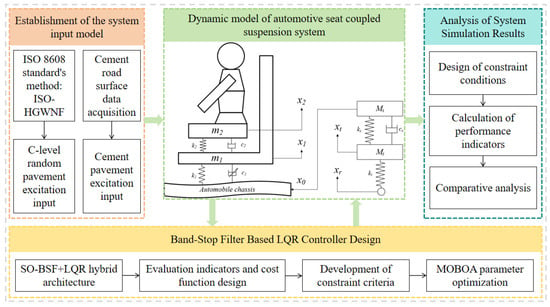
Figure 1.
Research technology roadmap for semi-active seat suspension.
2. Road Excitation Modeling and Semi-Active Seat Suspension System Formulation
2.1. Class C Random Pavement Excitation
The power spectral density (PSD) has become the predominant metric for characterizing the statistical properties of road roughness profiles. The analytical expression for the road PSD Gq(n) is mathematically formulated as follows:
where n signifies the spatial frequency (m−1), with n0 = 0.1 m−1 serving as the reference spatial frequency; Gq(n0) corresponds to the road roughness coefficient (m3); and the frequency index W is fixed at 2. As specified in the ISO 8608:2016 [2] international standard, road profiles are systematically classified into eight distinct grades (A-H) based on their roughness coefficients. The standard rigorously defines the geometric mean of the roughness coefficient Gq(n0) for each grade and the geometric mean of root-mean-square (RMS) roughness values across the 0.011–2.83 m−1 spatial frequency bandwidth. The complete set of classification parameters is presented in Table 1.

Table 1.
Classification standards for road roughness profiles 1.
This research adopts the Gaussian white noise generated after second-order Butterworth filter treatment C-level random road roughness excitation signals. The stochastic road excitation function Zq is formulated as follows:
where Zq represents the amplitude of stochastic road excitation; Gq(n0) denotes the road unevenness coefficient; u indicates the vehicle’s longitudinal velocity, set to 20 m/s; ω(t) corresponds to uniformly distributed Gaussian white noise with zero mean and unit intensity; and f0 refers to the filter’s lower cutoff frequency, assigned as 0.01 Hz.
2.2. Cement Pavement Irregularity Acquisition Based on Vibration Response of Suspension System
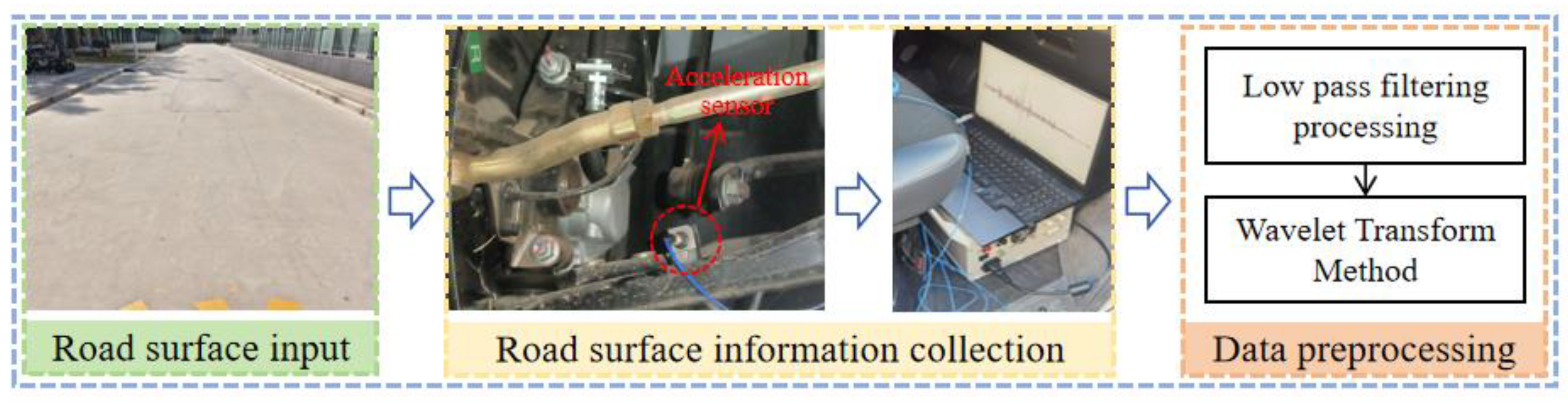
This study employs a real-vehicle experimental method to collect road roughness data on cement pavements. The experimental system architecture is illustrated in Figure 2. A conventional cement pavement was selected as the test site, and a triaxial accelerometer installed at the wheel hub center was used to acquire wheel center acceleration signals in real time during vehicle travel. To ensure data reliability, the test data from stable vehicle driving segments were selected as the final analysis samples. In terms of data acquisition system design, this study carefully considered the optimal selection of sampling frequency. An excessively low sampling frequency may lead to the loss of signal extremum points, compromising the characterization accuracy of road surface features, while an excessively high sampling frequency could result in data redundancy and impose higher demands on equipment performance. Accordingly, a sampling frequency of 1000 Hz was adopted in this experiment, achieving an optimal balance between data quality, acquisition efficiency, and device performance.
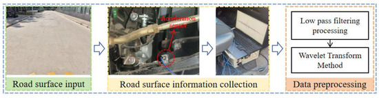
Figure 2.
Data collection process.
To accurately extract road excitation information, the experimentally measured wheel center acceleration data must undergo systematic preprocessing. Firstly, a zero-phase low-pass filter with a cutoff frequency of 50 Hz is applied to the raw signals. This frequency threshold is determined based on two key considerations: on the one hand, it effectively suppresses interference components such as sensor noise and high-frequency tire vibrations; on the other hand, it fully preserves the dynamic response characteristics of the suspension system within the 0–15 Hz frequency range. To address the low-frequency baseline drift caused by variable-speed driving, a wavelet transform method is adopted for trend removal after a comparative analysis. Compared with traditional polynomial fitting, this approach demonstrates superior performance in retaining local signal features. Finally, based on multibody dynamics theory, a mapping relationship between wheel center acceleration and road excitation is established. Road elevation profiles are reconstructed through coordinate transformation and time-domain integration.
2.3. Seat Suspension System Input Model
Initially, stochastic excitations induced by road roughness propagate through the tire-road interface to the wheel subsystem. The vibrations are then transferred to the vehicle body structure following primary damping through the automotive suspension system. Ultimately, the vibrations reach the human body via the seat suspension system. The physical transmission sequence can be represented as follows: Road excitation → Wheels → Vehicle suspension → Body structure → Seat suspension → Occupant.
For the vibration damping performance analysis of a semi-active seat suspension, the foremost objective is to precisely identify the input excitation characteristics of the suspension system. The controller design in this study is established under the following assumptions: (1) the vibration transmission is restricted to the vertical direction; (2) coupled vibration effects in the lateral and longitudinal directions are disregarded; and (3) system parameters are time-invariant features. The adoption of a quarter-vehicle model as the analytical foundation is primarily based on the rationale that, despite its simplification to a single-wheel suspension system, this model can effectively capture the principal vertical dynamic behaviors of the vehicle body, including key indicators like body bounce and suspension travel, via judicious parameter configuration.
As illustrated in Figure 3b, the developed quarter-vehicle model functions as a front vibration filtering system, producing outputs with two key vibration components: (1) low-frequency vibrations (0–5 Hz), induced directly by road roughness, and (2) mid-frequency vibrations (8–12 Hz), arising from body resonance. The filtered vibration signals are subsequently utilized as input excitation boundary conditions for the “human-seat” suspension system. The system dynamics model derived from Newton’s second law is expressed as follows:
where Mt represents the tire mass; Ms signifies the vehicle body mass; kt denotes the tire stiffness; ks refers to the suspension stiffness; and cs characterizes the suspension damping coefficient. This formulation maintains technical precision while adopting concise terminology conventions commonly used in vehicle dynamics research.
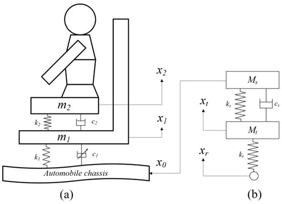
Figure 3.
Dynamic model of vehicle-seat coupled suspension system. (a) Model of vehicle suspension. (b) Two-degree-of-freedom “human-seat” suspension system model.
2.4. Modeling of Semi-Active Seat Suspension System
Prior to performing dynamic analysis on the “human-seat” suspension system, a precise description of its dynamic model is required. In developing the dynamic model for the “human-seat” suspension system, the MR fluid damper is simplified as an actuator capable of directly generating the actuation force. The resulting actuation force is denoted as F(t). To accurately describe the dynamic behavior of the shock absorber, the improved Bingham model can be adopted. According to the research of Fernando Viadoro-Monasterio et al. [28], this model can accurately characterize the hysteresis effect by introducing the hyperbolic tangent function, and its expression is shown as Equation (4).
where F(t) is the output force of the MR damper; i is the input current; zdef is the damper displacement; a0, a1, a2, and a3 are the model parameters determined by experimental calibration in reference [28]; and V0/X0 is the ratio of the critical velocity of hysteresis to the critical displacement.
The developed semi-active “human-seat” suspension system model for the vehicle is illustrated in Figure 3a. The system’s dynamic behavior is governed by the following:
where m2 denotes the mass of the human body; m1 represents the mass of the seat; c2 corresponds to the damping coefficient of the seat cushion; and k2 signifies the stiffness coefficient of the cushion. The parameters c1 and k1 denote the damping and stiffness coefficients of the MR damper, respectively. The variables x2 and x1 refer to the vertical displacement of the human body and seat, while ẋ2 and ẋ1 describe their vertical velocities. Similarly, ẍ2 and ẍ1 represent the vertical acceleration of the human body and seat, respectively. Additionally, x0 represents the excitation input from the vehicle body to the seat, and F(t) signifies the damping force generated by the MR damper.
Based on the aforementioned dynamic model, the state-space representation of the system can be expressed as follows:
where the state vector is ; the control input is ; the road disturbance is ; and the system matrix A, input matrix B, and disturbance matrix E can be expressed as follows:
3. Band-Stop Filter-Based LQR Controller Design
As intelligent driving becomes widespread, motion sickness challenges for vehicle occupants have grown more prominent. Vertical vibration in the frequency band of 0.1–0.5 Hz is most likely to cause occupant discomfort, which is closely related to the physiological sensitivity of vestibular organs, according to ISO 2631-1: 1997 [29] Evaluation Standard for Human Body Vibration. This study is based on the target frequency band established by this international standard and focuses on improving symptoms of dizziness by mechanical vibration attenuation, the effectiveness of which has been verified by a significant reduction in the vibration acceleration-weighted RMS value. The frequency-weighted LQR control method specifically addresses the motion sickness-sensitive frequency range (0.1–0.5 Hz) through the integration of frequency-domain objectives into the LQR quadratic performance metric. By incorporating a frequency response analysis with closed-loop pole configuration, this approach enables the accurate attenuation of vertical vibration energy within targeted frequency ranges. The design block diagram of the frequency-domain-weighted LQR control method proposed in this paper is shown in Figure 4.
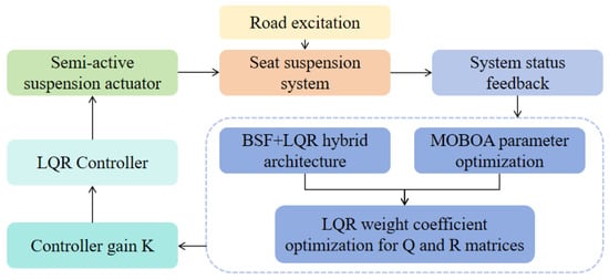
Figure 4.
Frequency-domain-weighted LQR control method.
3.1. Frequency-Domain-Weighted LQR Control Considering Comfort
A frequency-domain-weighted LQR control strategy was developed to address the comfort-oriented control problem in vehicle suspension systems. The primary innovation of this strategy is the incorporation of band-rejection filter features into the LQR control framework. This approach constructs an augmented state-space control system by coupling the state-space formulation of the band-rejection filter with the original suspension system’s state equations.
Inspired by the fractional SH-GH control framework [30] studied by Yujie Shen et al., the fractional model has higher parameter flexibility than the integer model in the suspension system. To improve the vibration attenuation within the frequency range sensitive to human motion sickness (0.1–0.5 Hz), a fractional-order band-stop filter is formulated as follows:
where ω0 is the central frequency (midpoint of the stopband); α denotes the fractional order (governing attenuation slope); and β represents the damping coefficient (influencing the bandwidth). The design core of the fractional-order band-stop filter (FOBF) is the parameter selection of fractional order α and center frequency ω0. The value of α directly affects the steep degree of the impedance attenuation characteristic. The value of α selected in this paper balances the impedance selectivity and the system realizability. Although the higher value of α can improve the roll-off performance of the edge of the impedance, it will lead to a significant increase in the complexity of the fractional-order system implementation. However, too low a value cannot meet the attenuation requirements of the target frequency band. The setting of ω0 strictly follows the sensitive characteristics of the human vestibular system to vertical vibration and is located in the center of the halo-induced frequency band. The complexity of the direct processing of the fractional-order state space necessitates the adoption of the approximation method, which approximates the amplitude-frequency and phase-frequency characteristics of the fractional-order operator in a specified frequency interval by means of a rational function and is a necessary transformation means for the engineering of the fractional-order control system. The stability of the closed-loop system is guaranteed by the dual mechanism. Firstly, the transfer function obtained by the Oustaloup approximation strictly satisfies the stability criterion. Secondly, the LQR controller ensures the global asymptotic stability of the augmentation system by solving the Riccati equation. The simulation study verifies the validity of the parameter design: significant suppression of vibration energy is observed in the target frequency band, and no energy leakage occurs in the adjacent frequency band, which indicates that the filter maintains the overall stability of the system while accurately controlling the vibration energy in the sensitive frequency band. Traditional state-space approaches apply exclusively to integer-order systems. For fractional-order systems, the fractional-order state equation needs to be introduced as follows:
where Dα is a fractional differential operator, and α ∈ (0, 1).
The discretization of fractional-order differential operators is essential for the numerical realization of fractional-order systems. In this study, the Grünwald–Letnikov (GL) method is employed to discretize the fractional-order differential operator Dα. The discretized form of Dα can be presented as follows:
where h is the sampling time step size; N is the discrete number of points corresponding to the current moment t; and the generalized binomial coefficient, defined as , would degenerate into the classical binomial coefficient when α is an integer.
The initialization coefficient is calculated recursively, and this operation is approximated by weighted historical data. The core of this operation is the convolution summation to obtain at time, where h is the sampling step size, and the fractional differential operator is .
Due to the complexity of directly handling fractional-order state-space equations, a common approach is to approximate sα as a high-order integer-order system before converting it into a state-space representation. The Oustaloup recursive approximation method is employed to represent the fractional differential operator sα as Equation (11) within the specified frequency band [ωl, ωh].
To preserve the fractional property, the equation of state is Equation (13).
Design the frequency-domain-weighted cost function as follows:
where Qaug and R represent weighting matrices, with . Through adjustment of the weighting matrices, suppression performance in targeted frequency bands can be optimized, while the control input weighting R regulates the trade-off between control effort and energy expenditure. The optimal gain matrix Kaug is derived through solving the Riccati equation, establishing the control law . Within the frequency-domain weighting framework, feedback regulation of filter states enables the adaptive adjustment of Qaug’s correlation coefficients, effectively amplifying the penalty weighting on filter outputs. This approach drives the controller to generate deeper spectral notches within motion-sensitive frequency ranges, thereby efficiently mitigating motion sickness symptoms induced by vestibular-visual conflicts.
3.2. Multi-Objective Butterfly Optimization Algorithm-Based Parameter Optimization
In the optimization of seat suspension systems, human body vibration frequency (HBVF), suspension working space (SWS), and human body acceleration (HA) serve as pivotal performance metrics that fundamentally determine vehicular comfort. As stipulated by the Chinese National Standard GB/T 13441.1-2007 [31], the 0.1–0.5 Hz low-frequency vibration range significantly induces motion sickness symptoms, necessitating targeted attenuation of vibration transmission within this critical band during suspension optimization. Strategic modulation of suspension stiffness and damping parameters enables the effective reduction of low-frequency vibration amplitudes, thereby shifting the human vibration frequency beyond the sensitive range and substantially decreasing the motion sickness incidence. Concurrently, constraining the suspension working space within optimal thresholds prevents mechanical interference while maintaining stability, whereas refinement of human body acceleration parameters minimizes vertical shocks to achieve comprehensive comfort enhancement. The formulated objective function is presented as follows:
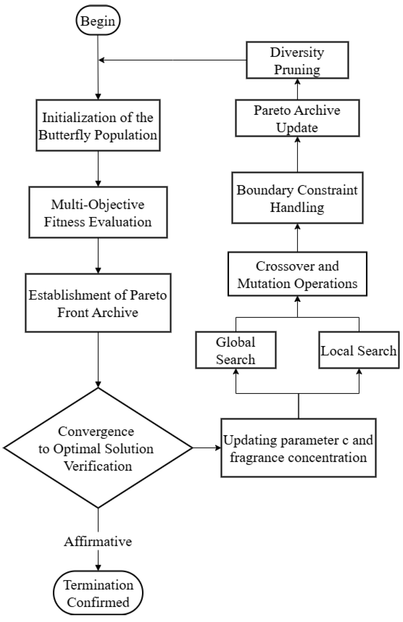
The selection of controller parameters critically influences the control gain matrix K in LQR, where varying parameter combinations can substantially alter the system performance characteristics. To enhance the controller optimization efficiency, this study proposes the multi-objective butterfly optimization algorithm for the efficient determination of optimal LQR weight matrices Q and R. The workflow for optimizing LQR weight parameters is depicted in Figure 5.
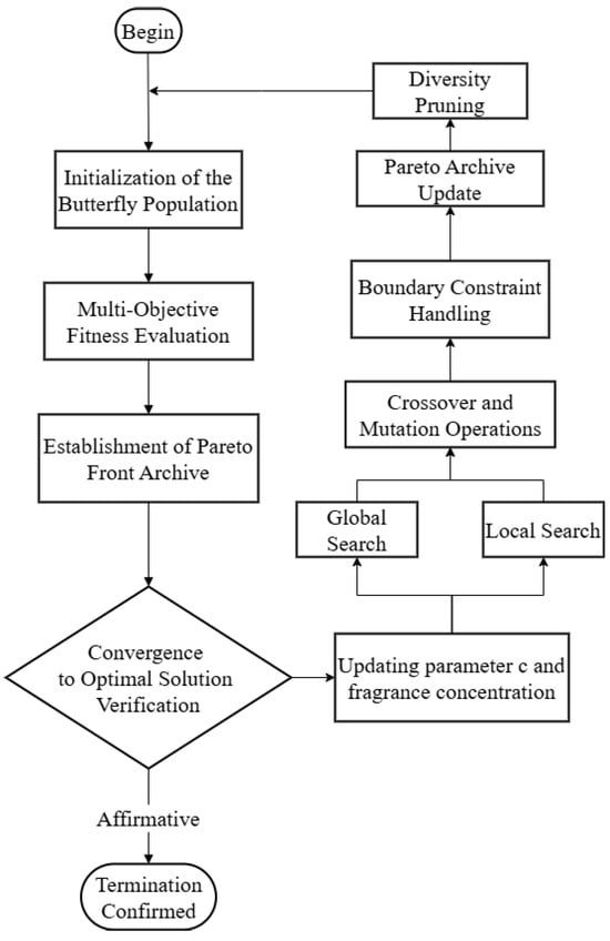
Figure 5.
Two-degree-of-freedom “human-seat” suspension system model.
The algorithm effectively explores Pareto optimal solution sets within the parameter space through biomimicry of butterfly swarm intelligence in foraging behavior, achieving balanced trade-offs among conflicting optimization objectives. Given that minimization constitutes the optimization direction for all objective functions, the multi-objective optimization formulation for the active seat suspension system is expressed as follows:
where represents the RMS value of the suspension working space (SWS); denotes the peak value of the human vertical acceleration (HA); and corresponds to the weighted amplitude of human vibration frequency within the sensitive frequency range (0.1–0.5 Hz).
According to Figure 5, the weight parameter optimization process of LQR can be divided into eight steps, as detailed below:
(1) The butterfly population is initialized by defining the population size N and selection criteria. Each individual is represented as , where D denotes the problem dimension. An initial population is formed by randomly generating N individuals corresponding to the weight parameters of the LQR controller. The algorithm parameters are configured with initial values, including the control coefficient c, scent concentration α, and transition probability p.
(2) Individual fitness assessment. The LQR controller model lacks the capability to verify if individual solutions (LQR weighting coefficients) represent global optima during implementation. Consequently, we integrate a fitness evaluation mechanism to improve the butterfly optimization algorithm, employing parallel computation to calculate multi-objective function values () for each solution, thereby simultaneously enhancing the convergence performance and population diversity.
(3) Pareto frontier management mechanism. The Pareto frontier management mechanism serves as the core component of multi-objective optimization algorithms, aiming to dynamically maintain a set of mutually non-dominated optimal solutions that balance the solution convergence and diversity. It identifies non-dominated solutions through dominance relationship evaluation, constructs solution hierarchies via fast non-dominated sorting, and dynamically merges new solutions with historical optima through an external archive. Archive maintenance employs a three-stage strategy (merge-redundancy removal-capacity control), coupled with crowding distance sorting or reference point methods to preserve the boundary solutions and sparse solutions with uniform distribution in the objective space, thereby guaranteeing solution diversity. For high-dimensional objective spaces and computational complexity challenges, clustering selection, grid partitioning, and hypervolume contribution evaluation methods are implemented to enhance the storage efficiency. By employing systematic filtering and updating strategies, the mechanism delivers a Pareto optimal solution set that reflects trade-off relationships among objectives, thereby facilitating multi-criteria decision-making in complex engineering scenarios.
(4) Fragrance concentration is a key mechanism guiding the search, and its computation is based on the objective function value and distance information. For multi-objective optimization, the Pareto front solution set must first be scalarized, with common methods including the weighted sum approach or Tchebycheff decomposition. The fragrance concentration fi is calculated as follows:
where c is the perceptual modality parameter; Ii corresponds to the fitness scalar value of the solution; and α serves as the regulation exponent. By simulating the biological trait of butterflies perceiving fragrance intensity, this mechanism establishes a dynamic equilibrium between global exploration and local exploitation in the algorithm, where parameter c generally adaptively attenuates with iterations to improve the convergence performance.
(5) The search mode is switched through a dynamic equilibrium mechanism. The global-local search switching mechanism maintains the dynamic equilibrium using a probabilistic threshold p. When a random number r < p, the algorithm executes a global search, where individuals migrate toward elite solutions in the current Pareto frontier, while local search involving random perturbations within neighborhood solution space is activated otherwise. The switching probability p is initialized at 0.8, with adaptive adjustment capabilities based on iterative progression. This mechanism effectively balances the exploration–exploitation capabilities by biomimicking butterfly behavioral patterns: long-range pheromone tracking (global) versus proximal stochastic foraging (local). The global search utilizes a pheromone concentration-based attraction mechanism, whereas local search employs stochastic differential vectors for precision searching in confined regions.
(6) The evolutionary operation enhancement mechanism in MOBOA enhances the population diversity via genetic operators, which consist of two key operations:
① Binary crossover (SBX) is simulated, and parameterized crossover is used to generate offspring solutions as follows:
The offspring individuals are generated through the linear combination of the parent generation as follows:
where u is a uniformly distributed random number u ∈ [0, 1]; ηc is the cross-distribution index (controlling the degree of deviation between the offspring and the parent); and and are the selected parent individuals.
② Polynomial variation. Introducing controllable perturbations to enhance local search capabilities as follows:
Variation after data processing, such as the following:
where the mutation distribution index ηm (controlling perturbation intensity) and the maximum permissible mutation step size are the key parameters in the evolutionary algorithm. The SBX operator utilizes ηc to regulate the offspring distribution and preserve the population diversity, while polynomial mutation employs ηm to govern exploration granularity. Their synergistic interaction effectively prevents premature convergence, ensuring robust optimization performance through balanced exploration–exploitation dynamics.
(7) Boundary repair strategies are employed to address solutions that exceed constraints, ensuring the search process adheres to variable limitations. Typical approaches comprise random reset (re-generating feasible solutions within the domain), boundary reflection (mirroring solutions back into the feasible domain), and saturation truncation (clamping values to boundary limits), which preserve population diversity while guaranteeing solution validity.
(8) Verify whether the iteration number reaches 100 cycles or all parameter fitness criteria in the frequency-weighted LQR model are fulfilled. When the termination conditions are met, the algorithm terminates and exports the identified optimal parameters for the magnetorheological damper model; otherwise, revert to Step 4.
The optimization approach rigorously adheres to mathematical system stability constraints while simultaneously accounting for HBVF, SWS, and HA design specifications. A comprehensive cost function encompassing both ride comfort and motion sickness prevention indices was formulated. Through solving the LMI-constrained convex optimization problem, a set of LQR control parameters fulfilling all feasibility requirements was ultimately derived. This optimized procedure offers a systematic framework for multi-objective control design in automotive suspension systems.
4. Results and Discussion
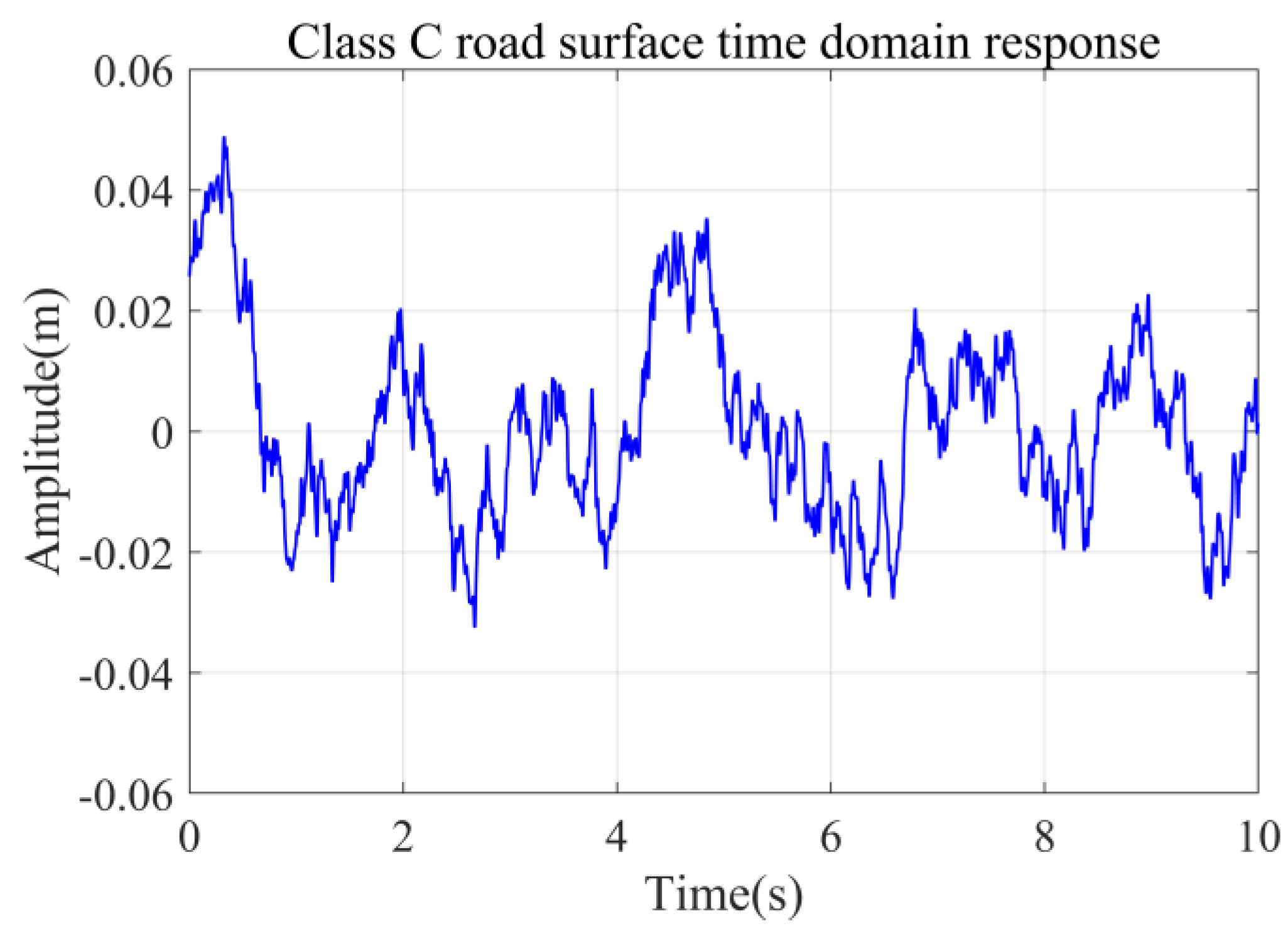
To comprehensively assess the semi-active suspension controller’s performance, this research utilizes two representative road excitations: Class C random road profiles based on ISO 8608 standards and experimentally acquired cement pavement data. The Class C random road profile characterizes typical medium-roughness road conditions, with a roughness coefficient of 256 × 10−6 m3. This parameter was incorporated into the power spectral density function to derive the Class C road roughness profile. Figure 6 presents the time-domain excitation signal of the implemented Class C random road profile.

Figure 6.
Class C simulates pavement time−domain response.
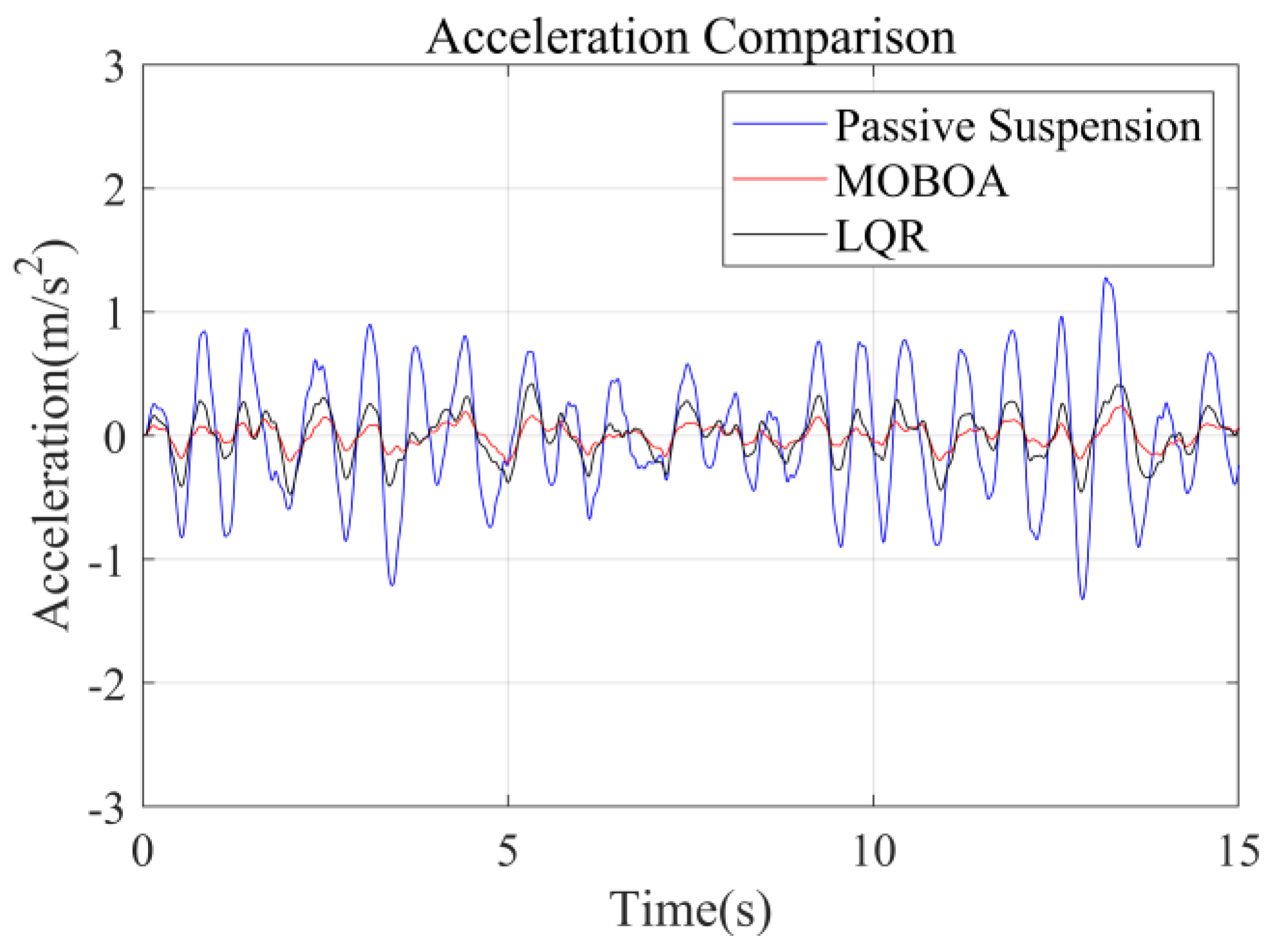
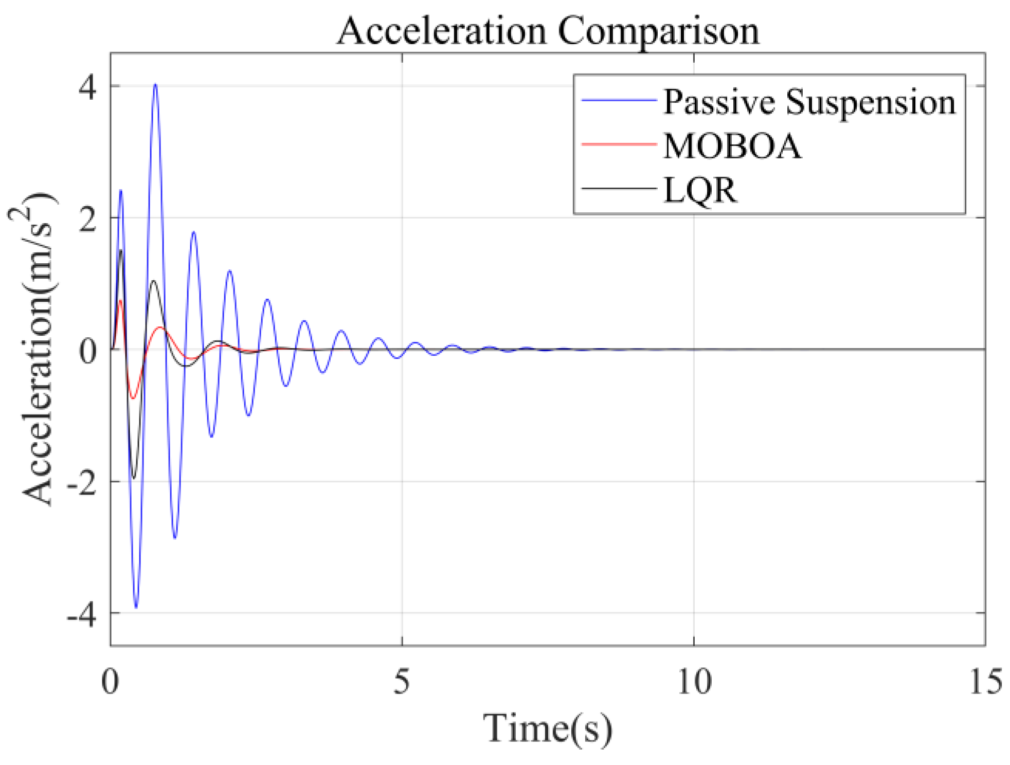
To systematically investigate the performance of the frequency-weighted LQR control strategy for semi-active seat suspensions, this study established a comparative experimental framework involving three control strategies: passive suspension, conventional LQR control, and the proposed frequency-domain-weighted LQR control. The simulations were performed under standardized Class C random road excitation conditions, with particular emphasis on evaluating vibration response characteristics of the human body across different control strategies. Figure 7, Figure 8, Figure 9 and Figure 10 display comparative results of vertical human body acceleration under identical operating conditions for the three control strategies, where the MOBOA-LQR control strategy exhibits notable technical superiority.
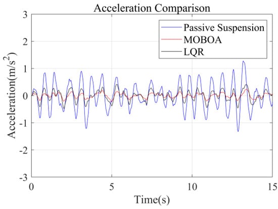
Figure 7.
Acceleration-time curve under C-class road surface.
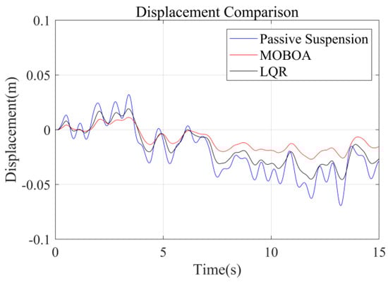
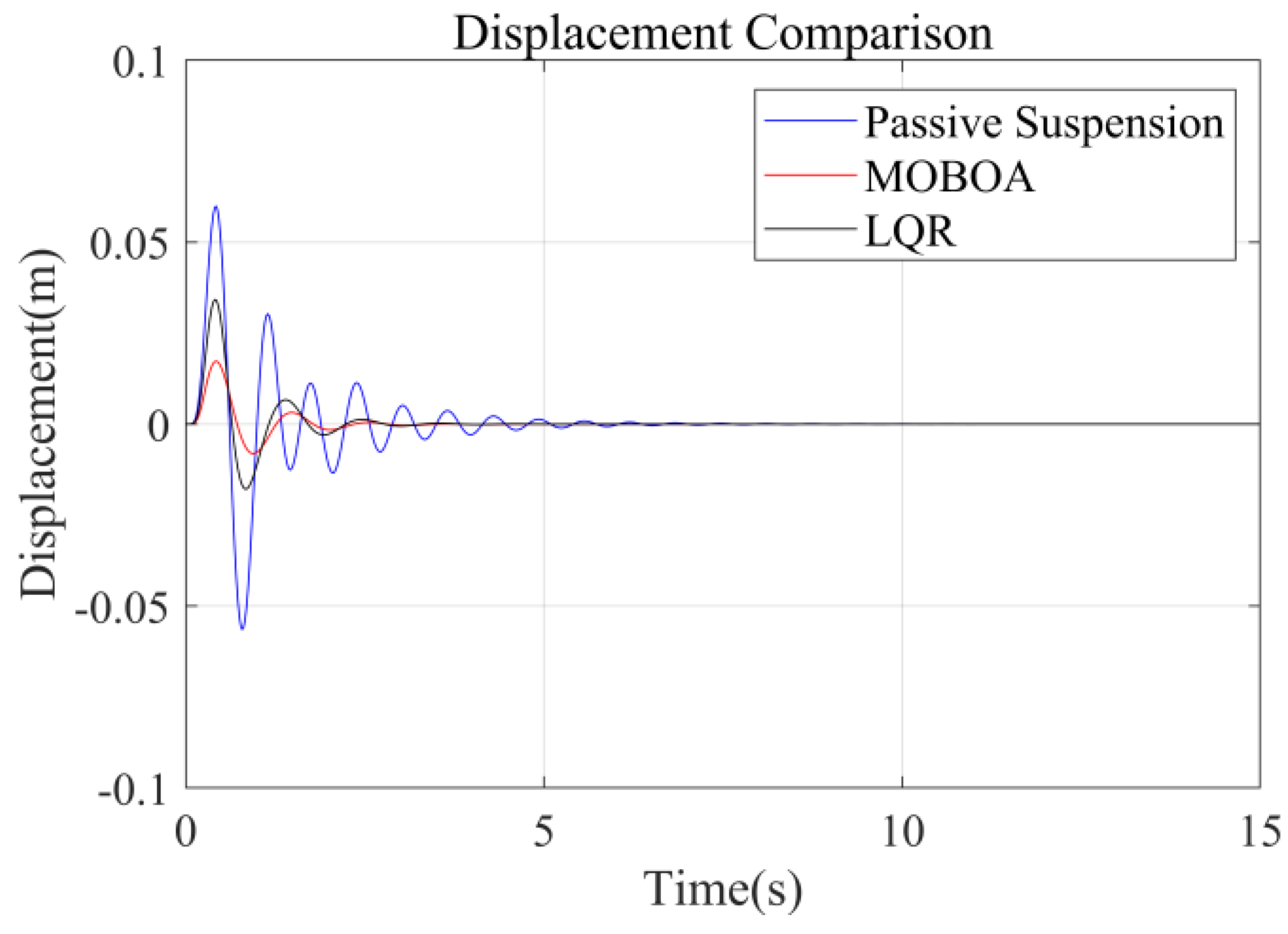
Figure 8.
Displacement-time curve under C-class road surface.
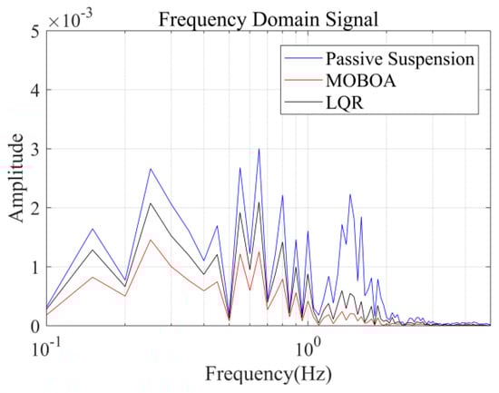
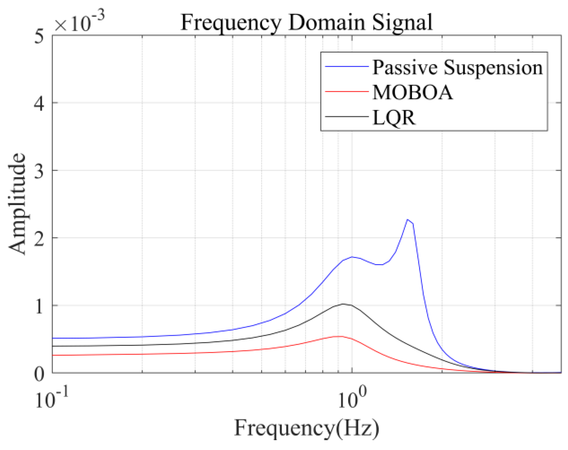
Figure 9.
Frequency-domain displacement curve under C-class road surface.
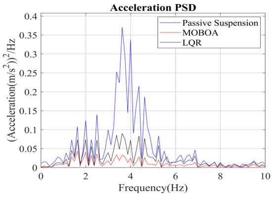
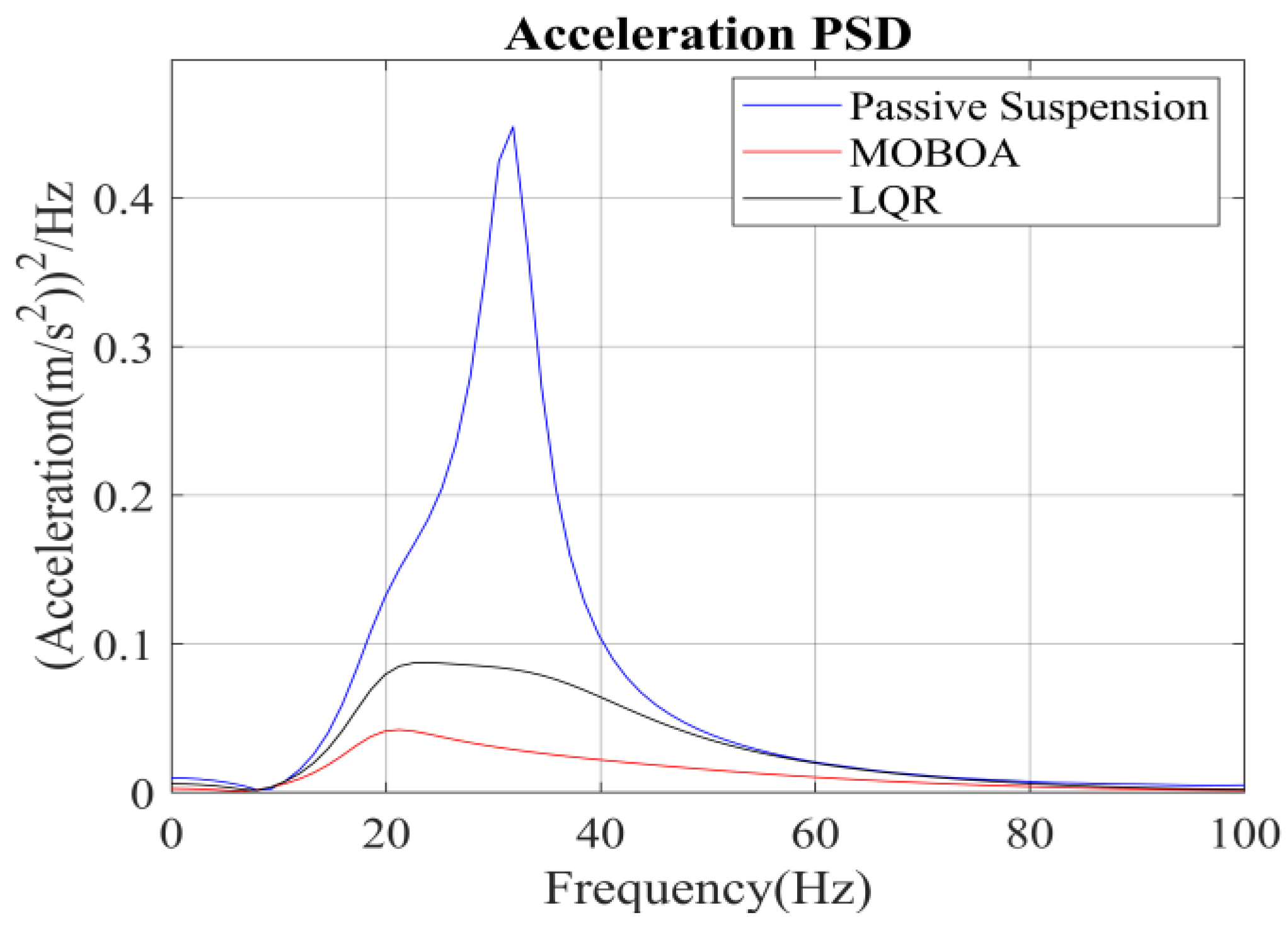
Figure 10.
Acceleration PSD under C-class road surface.
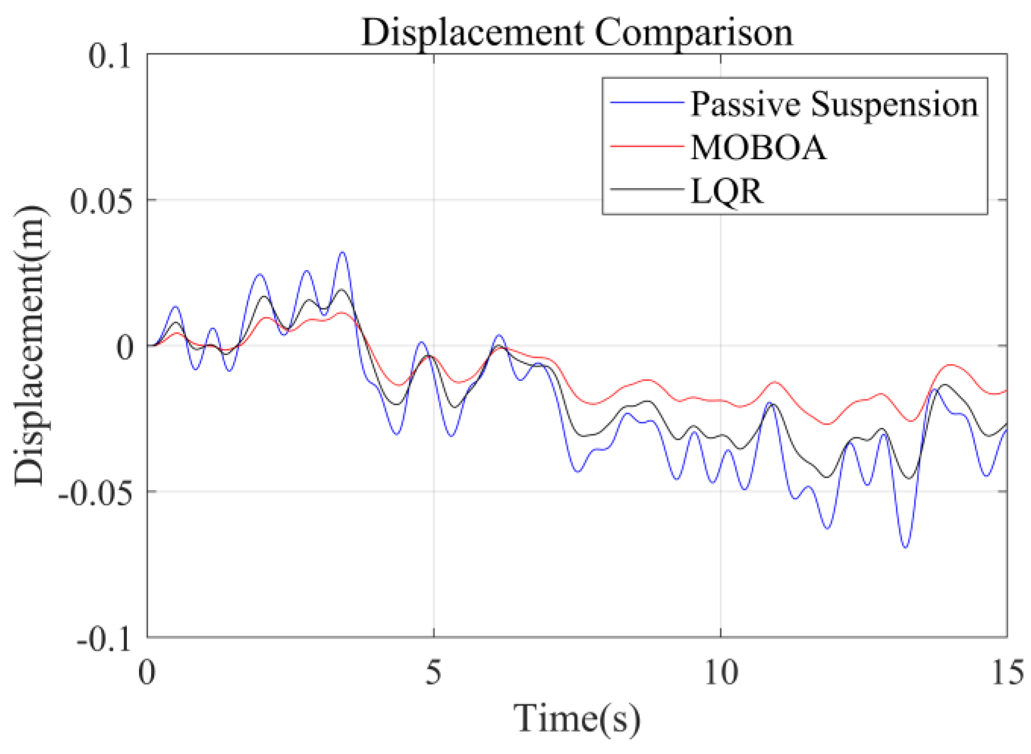
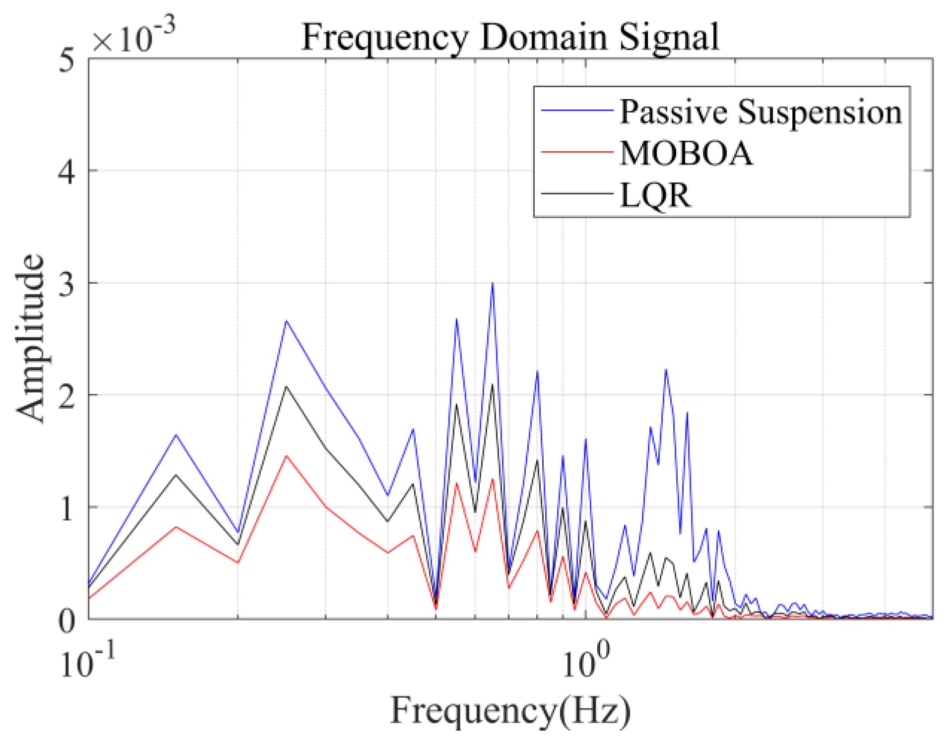
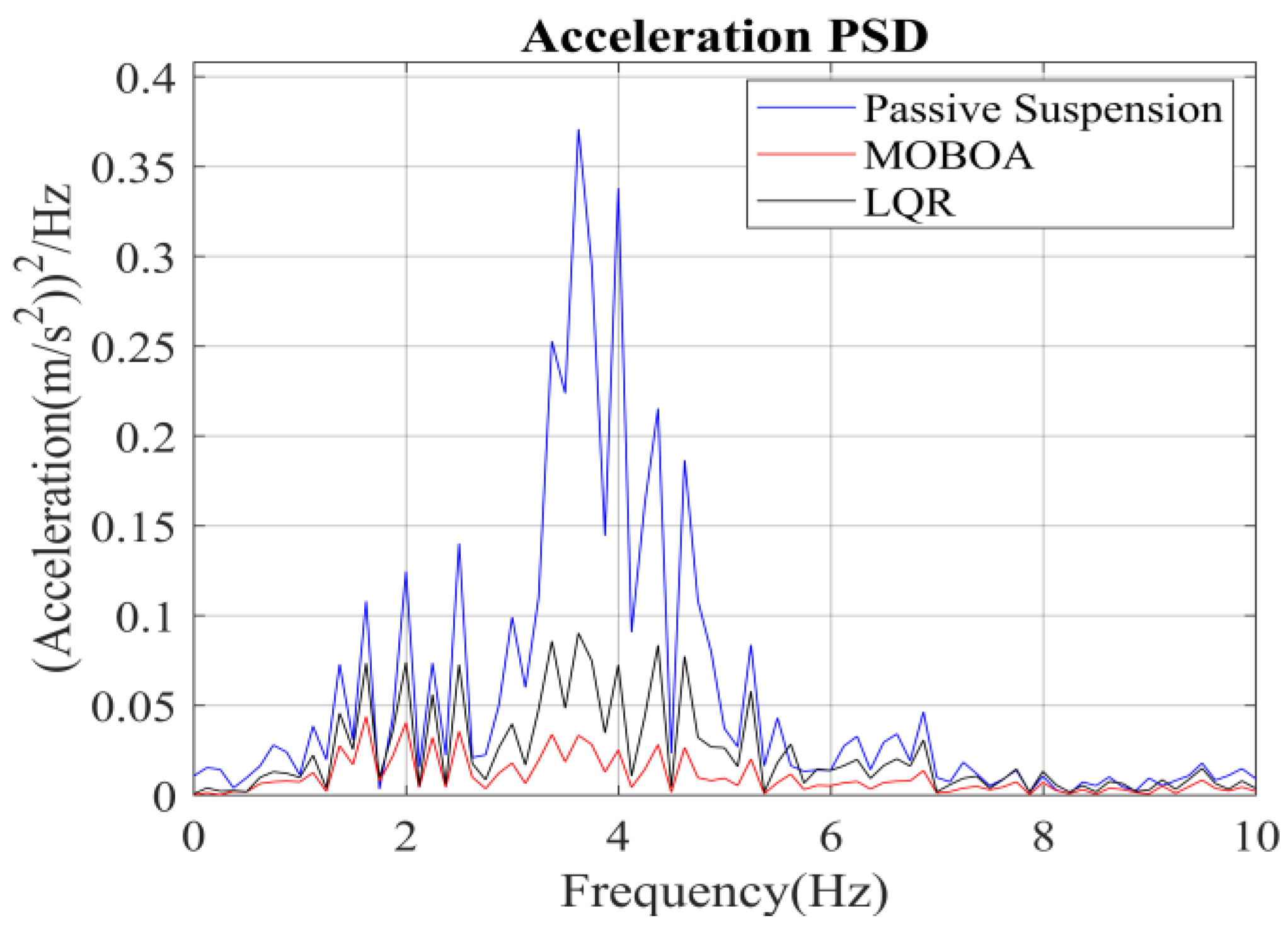
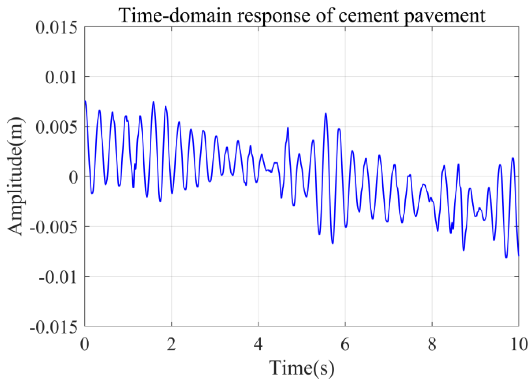
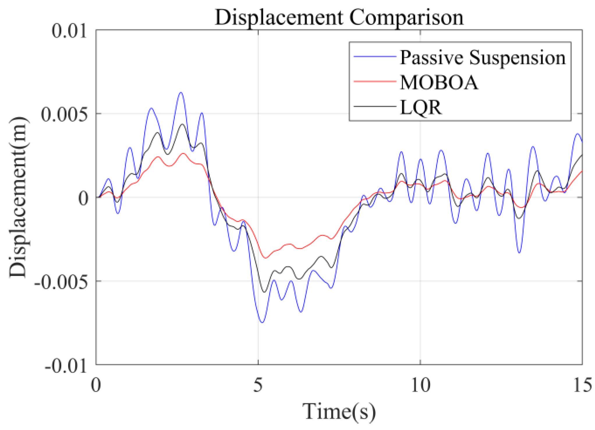
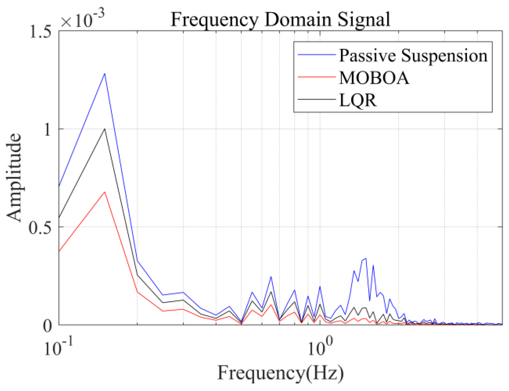
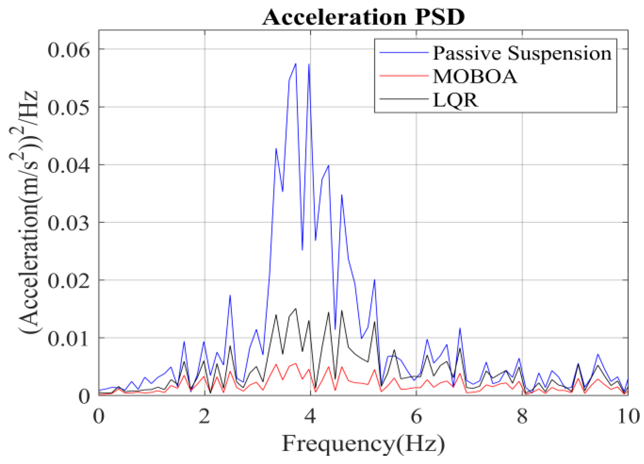
The measured cement pavement was adopted as a supplementary validation scenario in this study to evaluate the adaptability of control strategies under varied road excitation conditions. Figure 11 illustrates the excitation characteristics of the measured cement pavement, demonstrating distinct differences in road elevation time-history profiles compared to the Class C random road surface discussed earlier. Utilizing the measured road excitation data, Figure 12, Figure 13, Figure 14 and Figure 15 provide systematic comparisons of human vibration responses across three control configurations (passive suspension, conventional LQR control, and MOBOA-LQR control), with particular emphasis on key performance metrics such as vertical body acceleration and displacement.

Figure 11.
Elevation and time-history curve of cement pavement.
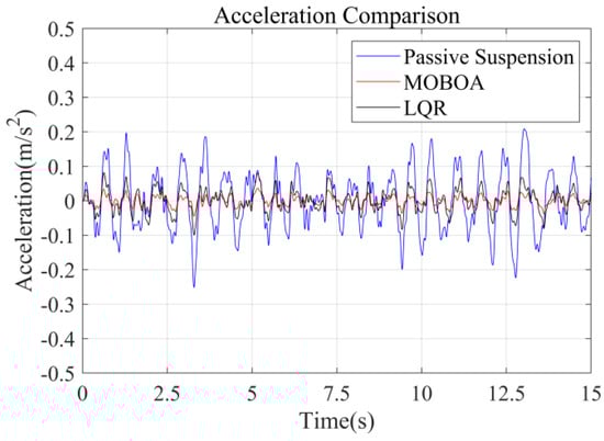
Figure 12.
Acceleration-time curve under cement pavement.
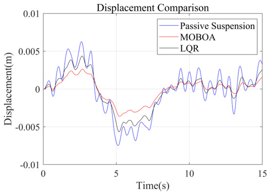
Figure 13.
Displacement-time curve under cement pavement.
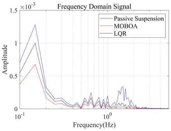
Figure 14.
Frequency-domain displacement curve under cement pavement.
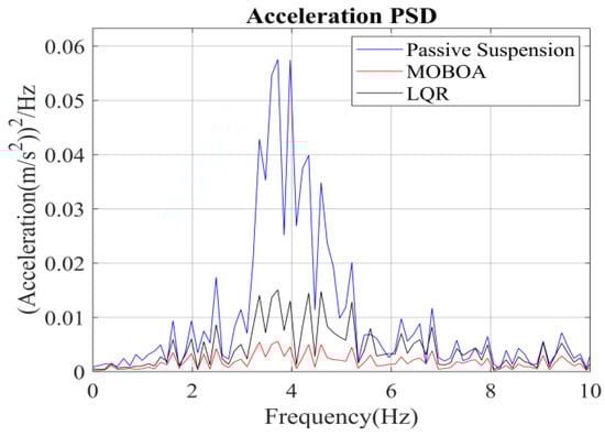
Figure 15.
Acceleration PSD under cement pavement.
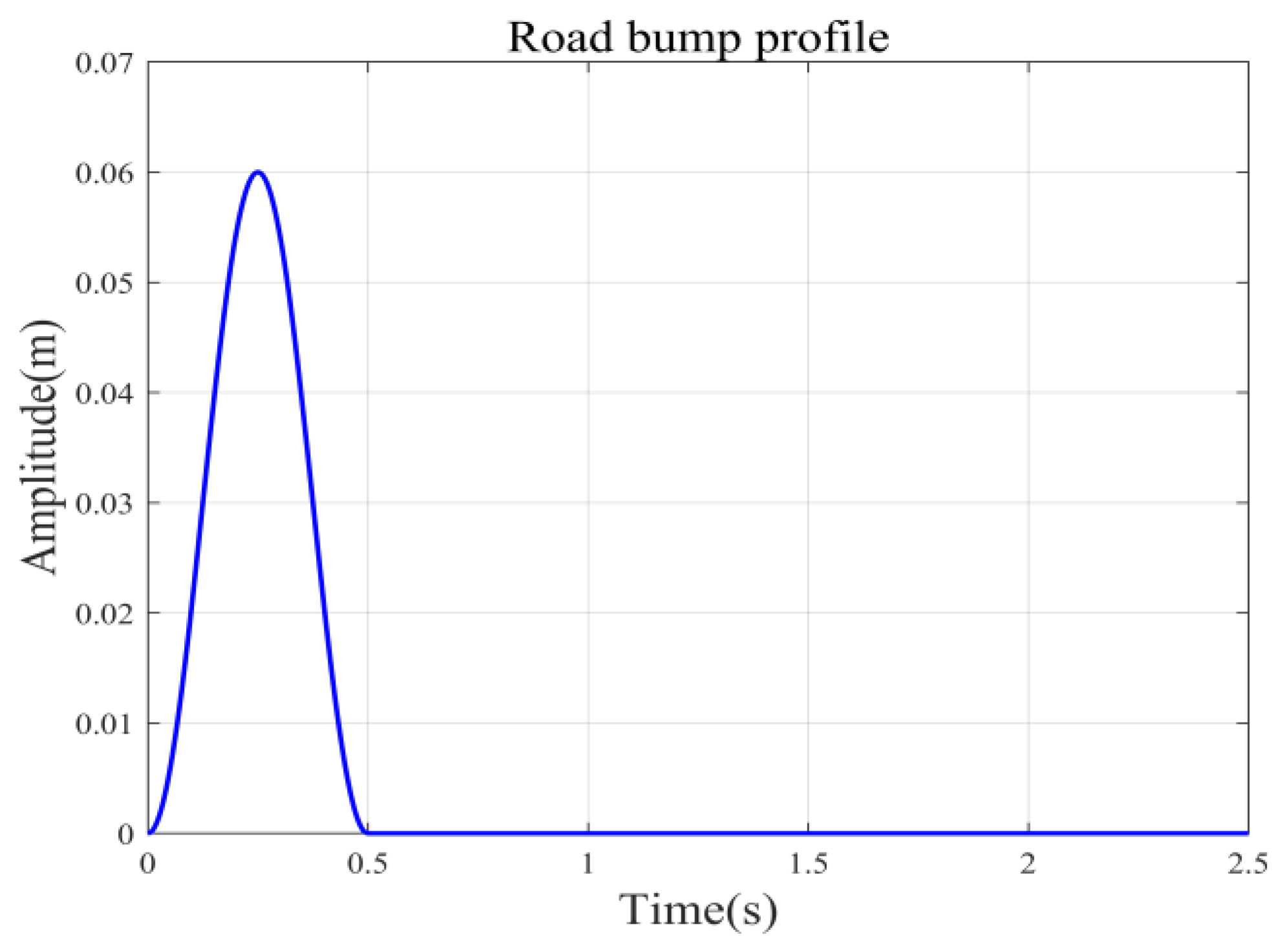
To analyze the performance of the suspension system under high-energy interference, speed bump pavement was selected for verification in this study. The speed bump pavement was modeled inspired by reference [28]. Formula (22) represents the contour of the speed bump pavement, and the road contour is shown in Figure 16.
where zr(t) is the input amplitude of the deceleration belt road, the height H = 6 cm, the length L = 5 m, and the speed V = 20 m/s.
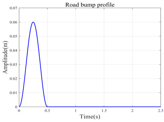
Figure 16.
The elevation and time-history curve of the speed bump pavement.
The simulation was carried out under the excitation conditions of the speed bump pavement, with a focus on investigating the vibration response characteristics under high-energy interference. Figure 17, Figure 18, Figure 19 and Figure 20 present the comparison results of the vertical vibration of the human body under the same working conditions by three control strategies. Among them, the MOBOA-LQR control strategy shows obvious technical advantages.
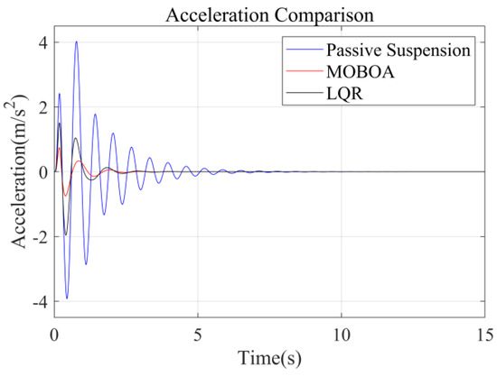
Figure 17.
Acceleration-time curve under the speed bump pavement.
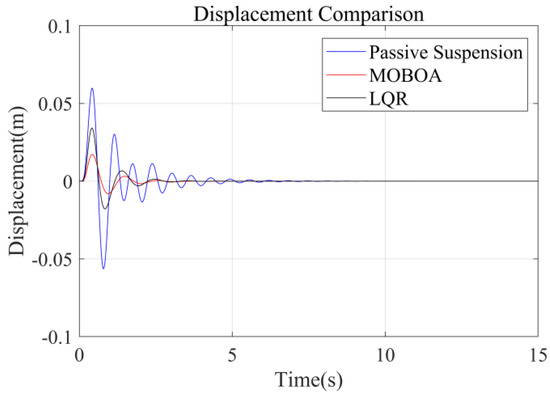
Figure 18.
Displacement-time curve under the speed bump pavement.
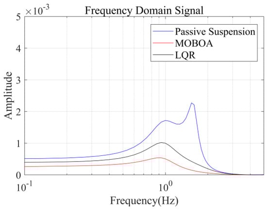
Figure 19.
Frequency-domain displacement curve under the speed bump pavement.
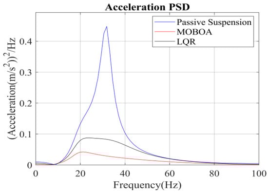
Figure 20.
Acceleration PSD under the speed bump pavement.
The frequency-domain analysis indicates that under the condition of C-level random pavement, the proposed control strategy achieves a significant vibration attenuation effect within the human body’s sensitive frequency band (0.1–0.5 Hz), which is highly consistent with the main spectral characteristics caused by motion sickness. To rigorously evaluate the control efficacy, comparative experimental results demonstrate that the MOBOA-LQR approach achieves a 41.04% reduction in human body displacement RMS and a 55.95% decrease in acceleration RMS relative to traditional LQR control systems. The quantitative metrics substantiate the technical merits of the proposed methodology for optimizing suspension system dynamics and elevating vehicular comfort performance.
5. Conclusions
To address motion sickness induced by low-frequency vertical vibrations (0.1–0.5 Hz) in automotive seat suspensions, this study develops a frequency-domain-weighted LQR control strategy with three distinctive advancements: (1) band-stop filter-LQR co-design enabling the frequency-selective attenuation of motion sickness critical vibrations through phase-matching compensation; (2) a multi-objective butterfly optimization algorithm that systematically optimizes the LQR weighting matrices (Q, R) by balancing conflicting requirements with regards to human body displacement limits, acceleration thresholds, and suspension travel; (3) Class C road profile-driven optimization using high-fidelity vehicle-road interaction models to replicate real-world urban driving disturbances. The simulation experiment verification shows that the proposed method reduces the incidence of motion disorders in standardized tests while maintaining the conventional ride comfort benchmark. Compared with the traditional LQR control, under the MOBOA control method, the root-mean-square value of human body displacement decreases by 41.04%, and the root-mean-square value of acceleration decreases by 55.95%. This dual-objective optimization bridges the gap between biomechanical comfort requirements and active control objectives in semi-active systems.
In this study, it should be pointed out that the effectiveness of the control algorithm is only verified by simulation, and there are some limitations. Firstly, all results are obtained based on MATLAB/Simulink 2022b and a vehicle dynamics model, and there is no real vehicle or bench test data. Secondly, the real engineering factors, such as real-time computing delay and sensor noise of the on-board ECU, are not considered in the study. Aiming at these limitations, the future research work will be promoted by stages: short-term planning to carry out hardware-in-the-loop tests to verify the execution efficiency of the controller on real-time platforms such as dSPACE. A 1:4 scale test rig with MR dampers is planned in the medium term to evaluate the dynamic response of the mechanical actuators. The long-term goal is to cooperate with the automobile enterprises to carry out the road test of real vehicles and collect subjective evaluation indicators of the human body (such as MSI value) to comprehensively verify the actual application effect of the control system.
Author Contributions
Conceptualization, Z.F. and M.J.; methodology, M.J.; software, M.J.; validation, M.J., Z.Z. and D.Z.; formal analysis, J.D.; investigation, Z.Z.; resources, Z.F.; data curation, M.J.; writing—original draft preparation, M.J.; writing—review and editing, M.J. and Z.F.; visualization, M.J.; supervision, Z.F.; project administration, S.R.; funding acquisition, Z.F. and D.Z. All authors have read and agreed to the published version of the manuscript.
Funding
This work was funded through five grants: the Henan Natural Science Fund for Distinguished Young Scholars 252300421015 [Funder: Zhijun Fu]; the National Natural Science Foundation of China (NSFC) 52472441 [Funder: Zhijun Fu]; the Henan Center for Outstanding Overseas Scientists GZS2023011 [Funder: Zhijun Fu]; the Key Research and Development Projects in Henan Province 231111241200 [Funder: Dengfeng Zhao]; and the Major Science and Technology Projects in Henan Province 241100240300 [Funder: Dengfeng Zhao].
Data Availability Statement
The dataset used in this research is available upon request by emailing the corresponding author.
Conflicts of Interest
The authors declare no conflicts of interest.
Abbreviations
The following abbreviations are used in this manuscript:
| LQR | linear quadratic regulator |
| MOBOA | multi-objective butterfly optimization algorithm |
| MSI | motion sickness incidence |
| MR | magnetorheological |
| ISMC | integral sliding mode control |
| PSD | power spectral density |
| RMS | root-mean-square |
| HBVF | human body vibration frequency |
| SWS | suspension working space |
| HA | human body acceleration |
References
- Asua, E.; Gutiérrez-Zaballa, J.; Mata-Carballeira, O.; Ruiz, J.A.; del Campo, I. Analysis of the motion sickness and the lack of comfort in car passengers. Appl. Sci. 2022, 12, 3717. [Google Scholar] [CrossRef]
- ISO 8608:2016; Mechanical Vibration-Road Surface Profiles-Reporting of Measured Data. ISO: Geneva, Switzerland, 2016.
- Zhao, Y.; Wang, X. A review of low-frequency active vibration control of seat suspension systems. Appl. Sci. 2019, 9, 3326. [Google Scholar] [CrossRef]
- Jeong, Y.; Yim, S. Design of active suspension controller for ride comfort enhancement and motion sickness mitigation. Machines 2024, 12, 254. [Google Scholar] [CrossRef]
- Fu, Q.; Wu, J.; Yu, C.; Feng, T.; Zhang, N.; Zhang, J. Linear quadratic optimal control with the finite state for suspension system. Machines 2023, 11, 127. [Google Scholar] [CrossRef]
- Rath, J.J.; Defoort, M.; Karimi, H.R.; Veluvolu, K.C. Output feedback active suspension control with higher order terminal sliding mode. IEEE Trans. Ind. Electron. 2016, 64, 1392–1403. [Google Scholar] [CrossRef]
- Dertimanis, V.K.; Chatzi, E.N. LQR-UKF active comfort control of passenger vehicles with uncertain dynamics. IFAC-Pap. 2018, 51, 120–125. [Google Scholar] [CrossRef]
- Yao, G.Z.; Yap, F.F.; Chen, G.; Li, W.H.; Yeo, S.H. MR damper and its application for semi-active control of vehicle suspension system. Mechatronics 2002, 12, 963–973. [Google Scholar] [CrossRef]
- Samaroo, K.; Awan, A.W.; Islam, S. Semi-Active Suspension Design for an In-Wheel-Motor-Driven Electric Vehicle Using a Dynamic Vibration-Absorbing Structure and PID-Controlled Magnetorheological Damper. Machines 2025, 13, 47. [Google Scholar] [CrossRef]
- Li, X.; Zhang, J.Q. Frequency weighted LQR controller design improvements. J. Natl. Univ. Def. Technol./Guofang Keji Daxue Xuebao 2021, 43. [Google Scholar] [CrossRef]
- Li, D.; Liu, F.; Deng, J.; Tang, Z.; Wang, Y. Nonlinear damping curve control of semi-active suspension based on improved particle swarm optimization. IEEE Access 2022, 10, 90958–90970. [Google Scholar] [CrossRef]
- Roebuck, R.L.; Cebon, D. Implementation of semi-active damping on a tri-axle heavy-vehicle suspension. Proc. Inst. Mech. Eng. Part D J. Automob. Eng. 2008, 222, 2353–2372. [Google Scholar] [CrossRef]
- Wu, J.L. A simultaneous mixed LQR/H∞ control approach to the design of reliable active suspension controllers. Asian J. Control 2017, 19, 415–427. [Google Scholar] [CrossRef]
- Yang, Y.; Liu, C.; Chen, L.; Zhang, X. Phase deviation of semi-active suspension control and its compensation with inertial suspension. Acta Mech. Sin. 2024, 40, 523367. [Google Scholar] [CrossRef]
- Cui, M.H.; Fu, Z.J.; Subhash, R.; Zhen, R.; Liu, Y. Adaptive Preview H∞ Control of Active Suspension Based on Road Recognition. Autom. Eng. 2025, 47, 508–518. [Google Scholar]
- Wei, C.; Cai, Y.; Zhang, K.; Wmag, Z.; Yu, W. Novel optimal design approach for output-feedback H∞ control of vehicle active seat-suspension system. Asian J. Control 2020, 22, 411–422. [Google Scholar] [CrossRef]
- Qiu, C.; Liu, X.; Shen, Y. Improvement of the vehicle seat suspension system incorporating the mechatronic inerter element. World Electr. Veh. J. 2023, 14, 29. [Google Scholar] [CrossRef]
- Yan, L.; Chen, J.; Duan, C.; Zhao, C.; Yang, R. A vibration control method using MRASSA for 1/4 semi-active suspension systems. Electronics 2023, 12, 1778. [Google Scholar] [CrossRef]
- Xie, P.; Che, Y.; Liu, Z.; Wang, G. Research on vibration reduction performance of electromagnetic active seat suspension based on sliding mode control. Sensors 2022, 22, 5916. [Google Scholar] [CrossRef]
- Konieczny, J.; Sibielak, M.; Rączka, W. Active vehicle suspension with anti-roll system based on advanced sliding mode controller. Energies 2020, 13, 5560. [Google Scholar] [CrossRef]
- Mai, V.N.; Yoon, D.S.; Choi, S.B.; Kim, G.W. Explicit model predictive control of semi-active suspension systems with magneto-rheological dampers subject to input constraints. J. Intell. Mater. Syst. Struct. 2020, 31, 1157–1170. [Google Scholar] [CrossRef]
- Ning, D.; Du, H.; Sun, S.; Li, W.; Zhang, B. An innovative two-layer multiple-DOF seat suspension for vehicle whole body vibration control. IEEE/ASME Trans. Mechatron. 2018, 23, 1787–1799. [Google Scholar] [CrossRef]
- Arora, S.; Singh, S. An improved butterfly optimization algorithm with chaos. J. Intell. Fuzzy Syst. 2017, 32, 1079–1088. [Google Scholar] [CrossRef]
- Gonzalez-Sanchez, B.; Vega-Rodríguez, M.A.; Santander-Jiménez, S. A multi-objective butterfly optimization algorithm for protein encoding. Appl. Soft Comput. 2023, 139, 110269. [Google Scholar] [CrossRef]
- Arora, S.; Singh, S. Butterfly optimization algorithm: A novel approach for global optimization. Soft Comput. 2019, 23, 715–734. [Google Scholar] [CrossRef]
- Li, M.; Xu, J.; Wang, Z.; Liu, S. Optimization of the semi-active-suspension control of BP neural network PID based on the sparrow search algorithm. Sensors 2024, 24, 1757. [Google Scholar] [CrossRef]
- Koch, G.; Fritsch, O.; Lohmann, B. Potential of low bandwidth active suspension control with continuously variable damper. Control Eng. Pract. 2010, 18, 1251–1262. [Google Scholar] [CrossRef]
- Viadero-Monasterio, F.; Meléndez-Useros, M.; Jiménez-Salas, M.; Boada, B.L. Robust Static Output Feedback Control of a Semi-Active Vehicle Suspension Based on Magnetorheological Dampers. Appl. Sci. 2024, 14, 10336. [Google Scholar] [CrossRef]
- ISO 2631:1997; Mechanical Vibration and Shock-Evaluation of Human Exposure to Whole-Body Vibration. ISO: Geneva, Switzerland, 1997.
- Shen, Y.; Li, J.; Huang, R.; Yang, X.; Chen, J.; Chen, L.; Li, M. Vibration control of vehicle ISD suspension based on the fractional-order SH-GH stragety. Mech. Syst. Signal Process. 2025, 234, 112880. [Google Scholar] [CrossRef]
- GB/T 13441.1−2007; Mechanical Vibration and Shock-Evaluation of Human Exposure to Whole-Body Vibration—Part 1: General Requirements. National Standard of the People’s Republic of China: Beijing, China, 2007.


Disclaimer/Publisher’s Note: The statements, opinions and data contained in all publications are solely those of the individual author(s) and contributor(s) and not of MDPI and/or the editor(s). MDPI and/or the editor(s) disclaim responsibility for any injury to people or property resulting from any ideas, methods, instructions or products referred to in the content. |
© 2025 by the authors. Licensee MDPI, Basel, Switzerland. This article is an open access article distributed under the terms and conditions of the Creative Commons Attribution (CC BY) license (https://creativecommons.org/licenses/by/4.0/).