1. Introduction
On average, 60% of the world’s people and cargo are transported by vehicles that move on rubber tires over roads of various construction types, compositions, and qualities [
1,
2]. The number of such vehicles—including cars and all types of trucks—is continuously increasing [
3]. While this growth has a positive impact on accessibility, it also has an increasingly negative effect on human interaction and relationships with the surrounding environment [
4,
5]. This diversity of vehicles, due to their physical impact and emissions [
6,
7], contributes to several negative outcomes [
8], including energy waste [
9,
10], pollution from harmful compounds [
11], road surface degradation [
12], and traffic congestion—leading to time loss [
13], rising social tension [
14], reduced safety [
15,
16], and diminished comfort [
17,
18]. Above all, traffic safety depends on the interaction between the human factor [
19], the vehicle, and the road system—encompassing both active and passive safety control measures [
20].
However, it should be remembered that transport systems are complex (systems of systems) nonlinear dynamic systems. Comprehensive engineering of such systems involves several key processes, including modeling/identification, simulation, system state monitoring/measurement, and control/optimization [
21].
In the scientific field, issues of nonlinear dynamics are most examined from the following perspectives:
Some scientific articles have examined the nonlinear longitudinal traction dynamics of ground vehicles, specifically analyzing detailed models of single-track vehicles with rubber tires under straight-line braking and acceleration conditions [
22].
Other researchers present simplified lateral and turning models of mechanical vehicles, considering rolling constraints. The governing equations are derived using the Appellian system. Analytical and numerical bifurcation analysis is performed using a PD controller. These results provide insights into the local and global stability of forward and backward motion in automated passenger vehicles [
23].
Some researchers develop analytical modeling approaches aimed at capturing the nonlinear lateral dynamic behavior of Double-A HCT (high-capacity transport) vehicle combinations on low-friction road surfaces [
24].
Li et al. [
25]., in their scientific work, present a nonlinear vehicle–road coupled model consisting of a seven-degree-of-freedom (DOF) vehicle and a simply supported double-layer rectangular thin plate resting on a nonlinear viscoelastic foundation. The model considers nonlinearities in suspension stiffness, suspension damping, and tire stiffness, and applies the Leaderman relationship and the Burgers model to characterize the nonlinear and viscous properties of asphalt pavement materials. The equations of motion for the vehicle–road system are derived, and the partial differential equation of the pavement is discretized into an infinite set of second-order ordinary differential equations and first-order ordinary differential equations using the Galerkin method and mathematical transformation [
25].
Scientific research is investigating the distribution and parameters of the frequency-weighted acceleration of passenger car seat surfaces and feet using detailed in-situ measurements. The lognormal probability density function (PDF) was identified as the most suitable analytical model for seat vibrations, which can be used to predict ride comfort and evaluate the statistical characteristics of seat surface acceleration. The study found that the scale and shape parameters of the lognormal PDFs increased linearly with road roughness statistics and that the influence of road roughness level was more significant than vehicle speed [
26].
In studies conducted by Akbari and Margolis [
27], a nonlinear biomechanical model of the upper body was developed to investigate disturbances transmitted to passengers by the vehicle. The model accurately replicates experimental data and accounts for flexural motion. It predicts low-amplitude sagittal movements and provides greater geometric and analytical insight into the internal dynamics of the upper body. The model indicates that the peak vibration transmission frequency is 4.5 Hz, which can be valuable for vibration reduction and control system design.
However, it is important to note that urban road users frequently drive over manhole covers, which can cause discomfort and potential health issues. Kirbas [
28] evaluated the vibrations experienced during such rides using ISO 2631 standards and vibration parameters. The level of discomfort increased with both driving speed and manhole cover depth. The highest discomfort levels were recorded at 30 km/h with a depth of 5.0 cm, at 20 km/h with a depth of 7.5 cm, and at 10 km/h with a depth of 10 cm. The Se parameter indicated that steep transition slopes of any kind have a more negative impact on lumbar spine health compared to diagonal transitions, while the slopes before and after manholes lose their significance.
Fu et al. [
29] assess driving safety and comfort based on vehicle-induced violations (VIV) using two perspectives: the vehicle’s dynamic response and the driver’s vision. These studies quantitatively evaluate the development and impact of blind spots with VIV, revealing that driving comfort—based on the vehicle’s dynamic response—is a key indicator for controlling vehicle speed. Increased vehicle speed, amplitude, and mode frequency negatively affect driving safety and comfort. The study also presents an appropriate driving safety equation based on the driver’s vision, demonstrating broad applicability [
30].
Some scientific studies address the gap in knowledge regarding the impact of autonomous vehicles (CAVs) on passenger comfort. One such study presents a method for analyzing and optimizing the stability of mixed CAV traffic flow, taking into account local control systems. The methodology calculates the stability diagram of local vehicle platoons based on equilibrium speed and increased CAV feedback. The optimal control range for CAV feedback gain is found to be [0.445, 1], [0.115, 1], and [0.075, 1], respectively. The papers also evaluate the effect of CAVs on passenger comfort using numerical simulations. The results indicate that under high mainline traffic conditions, passenger comfort can be improved by 26.6576% to 40.9417%, and speed variance can be reduced by 31.3898% to 31.6481%. However, to accurately assess the impact of CAVs on passenger comfort, real-world CAV experiments are necessary [
31,
32].
Recent research examines a vibration control approach that uses both an optimal controller and suspension parameter optimization. Continuous speed bumps are implemented to simulate more complex and realistic driving conditions. The results show that the new approach can also improve ride comfort in autonomous vehicles crossing, for example, multiple speed bumps [
33].
The study by Surblys et al. [
12] examines the influence of different pavement types on vehicle dynamics, with a particular focus on vertical acceleration and its effect on unsprung mass, including wheels and suspension systems. Two categorization methods were used in this study: a neural network and a multinomial logistic regression model. The results of the study highlight the effectiveness of the neural network in the real-time categorization of road surfaces, improving the understanding of vehicle dynamics affected by pavement conditions.
For example, Yang et al.’s [
34] study presents a comprehensive nonlinear dynamic model of vehicle suspension systems with active control strategies aimed at improving vibration suppression. It reinforces the relevance of addressing system nonlinearities and supports the methodological approach adopted in our work.
Recent studies have shown that nonlinear vehicle models provide improved predictions of vehicle dynamics compared to their linear counterparts. For instance, Sun et al. demonstrated that nonlinear vehicle models offer more accurate predictions of suspended mass acceleration in suspension systems than linear models, which frequently overestimate accelerations [
31]. Similarly, Wan et al. reported that integrating nonlinear models with advanced algorithms such as the unscented Kalman filter significantly enhances the accuracy of state parameter estimation for distributed drive electric vehicles, underscoring the benefits for biometric data collection systems that require precise vehicle state data to gauge driver characteristics [
35].
The conducted analysis revealed that scientific studies tend to place greater emphasis on the technical parameters of vehicles and the nonlinear evaluation of interactions between specific elements. However, as technology continues to advance and more sophisticated systems emerge, it becomes increasingly important to consider the potential for integration. One such area is biometric technologies.
Nonetheless, it is essential to remember that a major concern in any biometric credential management system today is its potential vulnerability in protecting information sources—namely, safeguarding the genuine user’s template from both internal and external threats. Modern biometric authentication systems face various risks, one of the most serious being the vulnerability of the template database. As a result, some researchers propose methods that integrate conventional cryptographic techniques with biometric data. Their work presents biometric encryption systems that encrypt the biometric template using pseudo-random number generation based on nonlinear dynamics [
36].
To describe the stability of a vehicle driving in a straight line or along a curve, a linear mathematical model can be used to account for the majority of situations encountered in everyday practice. However, there are rare but significant cases where vehicle dynamics must be described using nonlinear models. An important example is accident-avoidance maneuvers, where a well-designed vehicle can make the difference between a dramatic incident and one that goes almost unnoticed [
37]. Another essential consideration is the potential application of biometric technologies.
Therefore, it can be stated that the convergence of hardware, materials, sensors, and artificial intelligence has introduced a new class of wearable devices with advanced computing and communication capabilities, serving various purposes such as health monitoring, fitness tracking, and entertainment. These devices handle sensitive personal information and require appropriate protection [
38]
Despite the continuous improvement of vehicle safety, enhancing road traffic safety remains a key issue in modern society. The design of effective road restraint systems plays an important role in this context [
39].
When examining the integration of biometric technology with vehicle vibration analysis, scientific articles pay more attention to: real-time PPG-based biometric identification [
40]; vehicle and driver monitoring systems using on-board and remote sensors [
41]; driver health monitoring and analysis [
42]; using fingerprint scanning [
43]; vehicle security system implementation [
44]; technological systems for improving thermal comfort of drivers [
45]; measurement of the effects of whole-body vibration on truck drivers [
46].
The aim of the paper is to investigate how nonlinear vehicle dynamics factors affect the accuracy of biometric data in passenger and driver assessment systems by applying an extended human–seat–vehicle model and analyzing vibration transmission through body segments.
This paper presents a new nonlinear human–seat–vehicle multibody model that concurrently captures both vertical and angular responses of the head–neck complex under varied driving speeds and road excitation conditions. Unlike other studies concentrating only on either linear dynamics or simplified body representations, the suggested method uses second-order Lagrangian formalism to produce complete motion equations and measure body segment-specific responses (RMS, VDV, modal structure). Under real-world transport conditions, the study evaluates the connection between vibration-induced mechanical loads and biometric data integrity—such as eye and head movement stability—uniquely. Moreover, it provides for the first time a speed-based prediction model that specifies the thresholds at which ISO 2631 comfort and safety limits are surpassed in different anatomical areas, therefore providing a new framework for including ergonomic and biometric safety into transport system design.
The aim of this study is to develop and analyze a coupled nonlinear dynamic model of the road bump–vehicle–human system, focusing on the vertical and angular vibration transmission to the driver’s upper body and head. By incorporating nonlinear damping, stiffness, and friction elements, the model allows for the assessment of biomechanical responses that are critical for the integrity of biometric signal acquisition and passenger comfort.
2. Materials and Methods
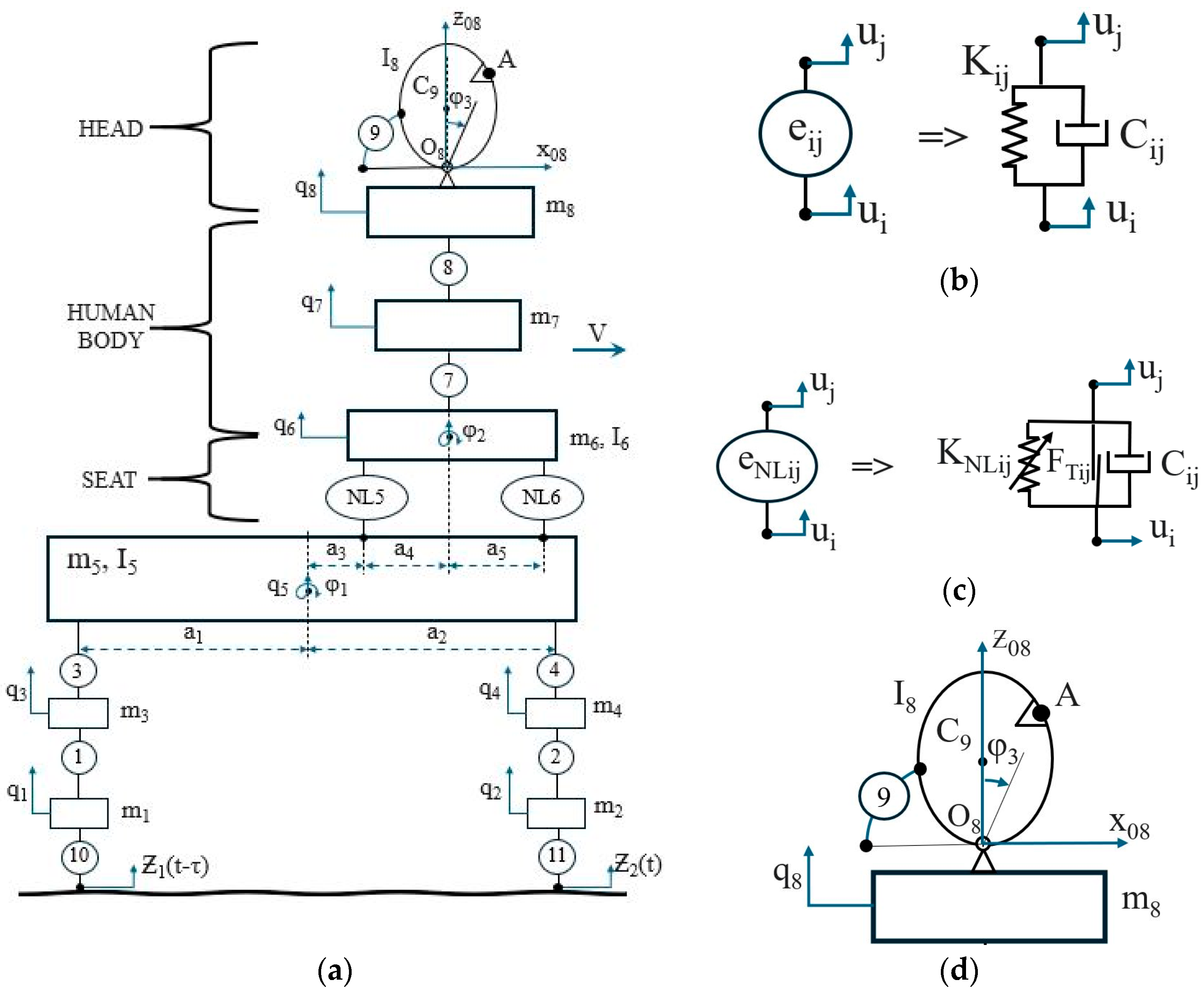
This paper analyzes the dynamic model of a car’s movement—the system (see
Figure 1a), which also takes into account the motion of the driver’s head while the vehicle is moving along a non-linear path.
The model is analyzed based on the computational scheme presented in
Figure 1a. The scheme is presented in the x-y Cartesian coordinate plane.
First, the generalized coordinates are defined, each corresponding to the displacement and rotation of a specific part of the system:
To calculate the kinetic energy, the velocities associated with each generalized displacement are determined:
The expression for the kinetic energy of the analyzed system is:
Road Surface and Tire Contact: Ground surface with road irregularities—represents an external excitation to the system, denoted as the height of road irregularities over time.
Tire Behavior: Springs
and
represent the stiffness coefficients of the tires. Dampers
and
—reflect the damping coefficients of the tires (
Figure 1b).
Suspension Springs and Dampers:ir stiffness coefficients of the suspension springs. and —coefficients of dampers that reduce vibrations.
Vehicle Suspension System: Body 1 (mass , )—represents the vehicle body.
Body Roll Effect: the angle indicates that the vehicle body can oscillate. Seat and Driver’s Body: Body 2 (mass , moment of inertia , angle )—represents the driver’s seat.
Springs and Dampers Between the Seat and the Vehicle Body: and represent the behavior of the seat (stiffness and damping).
Driver’s Body and Neck: Body 3 (mass ,)—the driver‘s (human) body. Spring and damper represent the behavior of the neck, allowing the head to move independently from the body.
Driver’s Head Orientation and Eye Movement: Body 4 (mass )—the driver’s head. The marked point on the sphere represents the driver’s eyes.
When the vehicle drives over uneven surfaces, the driver’s body moves along with the car’s body, but the head can move independently due to the flexibility of the neck. This means that the position of the eyes changes, and the driver must compensate for this motion to maintain a clear view. The analyzed model is based on the computational diagram presented in
Figure 1. The diagram is shown in the x–y Cartesian coordinate plane.
The expression for the potential energy of the analyzed system is:
where
is the Heaviside function.
The system includes damping elements such as shock absorbers, the seat, and human muscles. To calculate their effect based on velocities, the dissipative function is determined.
The expression for the dissipative energy of the analyzed system is:
where
The damping force is modeled as being proportional to the velocity difference between two moving points:
where elements of the vector
represent wheel–road interaction damping forces, which act depending on the relative velocities and road irregularities .
damping forces between the suspension elements and the upper structure, such as the vehicle body or the seat mount.
include complex damping interaction terms associated with seat oscillation and movement, involving both linear and angular velocities () between different structural points.
The distance parameters act as lever arms, amplifying or reducing the damping effect.
and describe interaction damping between the human torso and the seat, particularly considering the motion between the upper and lower parts of the torso and seat deformation.
terms represent damping of head motion, particularly between the neck, shoulders, and head segments.
pure rotational damping, meaning resistance to the head’s rotational motion, proportional to the angular velocity .
Next, the stiffness force vectors are calculated. These are the forces that aim to restore the initial (equilibrium) positions when deformation occurs. Such forces are typically proportional to the displacement differences between two points—according to Hooke’s law:
where elements of the vector
—dynamic and static friction coefficient
Next, the mass matrix of the analyzed system is constructed. The mass matrix is an essential component of the dynamic equations, especially when the analyzed system consists of multiple moving bodies with generalized coordinates. The mass matrix is formed from the derivatives of the kinetic energy concerning velocities.
General expression of the mass matrix:
The mass matrix M.
M of the analyzed system is constructed:
Next, the gravitational force vector is calculated.
After that, the overall system of equations is formulated
After calculating the overall motion of the entire system, we then proceed to compute the individual motion of body
(the driver’s head and eye movement)
Figure 1 and the motion of its components.
This is the generalized stiffness force vector, representing the forces arising from deformations.
This is the generalized damping force vector related to velocities, representing the forces caused by motion damping.
—This is the inertia force vector, representing forces that result from accelerations (mass influence).
a—This is the distance between two points and .
A (eye)—the acceleration vector of the eye is given as:
This expression shows the acceleration of point A, which includes rotational components (angular acceleration and centripetal acceleration) and vertical translational component
(see
Figure 1d).
The vehicle moves along a road with an obstacle (see the scheme in
Figure 2).
The following system parameters are used to obtain the results (see
Table 1).
Figure 2 below depicts a vehicle moving over a bump, a typical bump-over scenario used in vibration analysis and dynamic systems modeling.
Figure 2 is often used to illustrate how a vehicle and its suspension components respond to changes in the road profile and how this results in vibration transmission to the occupants or structural components.
3. Results
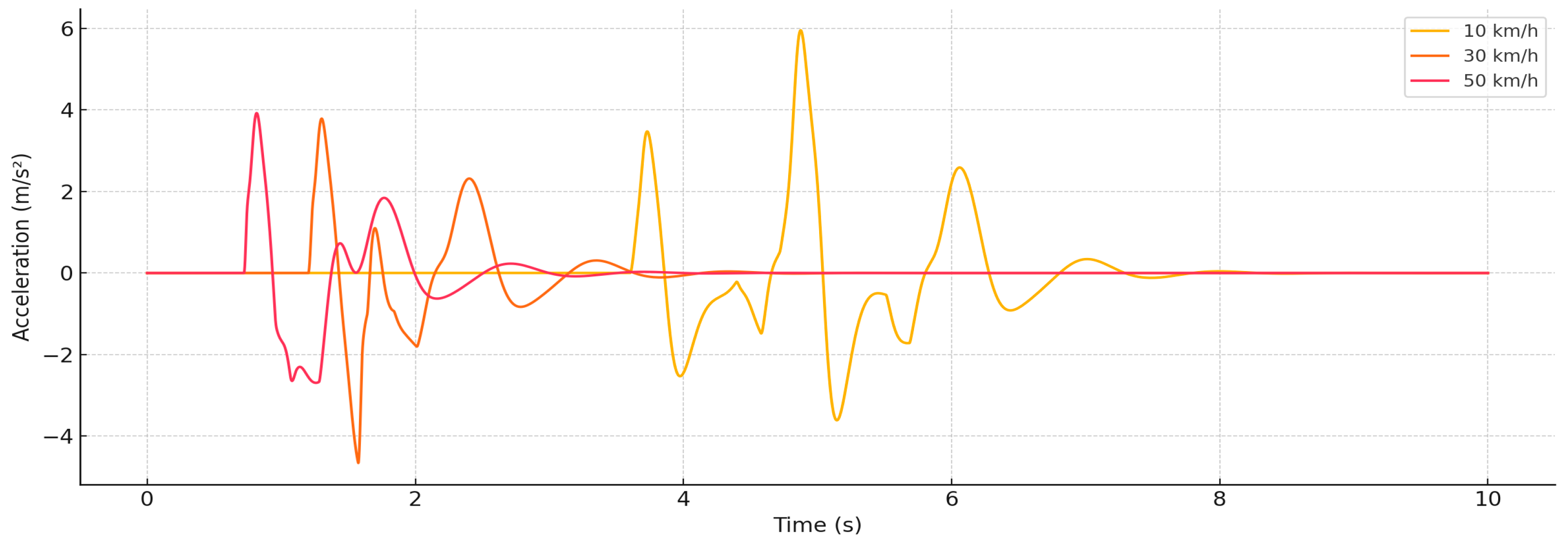
Figure 3 presents time-series data of vertical acceleration measured at the eye–head segment of the biomechanical multibody system when the vehicle passes over a road bump. Simulations were performed at three vehicle speeds: 10, 30, and 50 km/h. The results indicate a distinct shift in the nature of biomechanical response depending on speed. At the lowest speed (10 km/h), the vertical acceleration reaches a peak of approximately ±6 m/s
2, with the vibration impact beginning later (~4.5 s) and lasting longer. This suggests a low-frequency, extended-duration excitation that gradually propagates through the body.
In contrast, at 50 km/h, the vertical acceleration peaks at only ±2 m/s2, but the vibration occurs much earlier (~1.2 s) and the waveform becomes sharper and shorter in duration. This illustrates a transition to a high-frequency, impulsive load, which is more efficiently damped by the spine and neck tissues. The reduced amplitude at higher speeds is attributed to the effective damping properties of soft tissues and musculature that suppress higher-frequency inputs. However, while linear acceleration decreases with speed, the increase in frequency and energy density may disrupt visual fixation and degrade the reliability of biometric systems such as eye tracking. This makes the eye–head segment especially important in ergonomic and safety evaluations of vehicle dynamics.
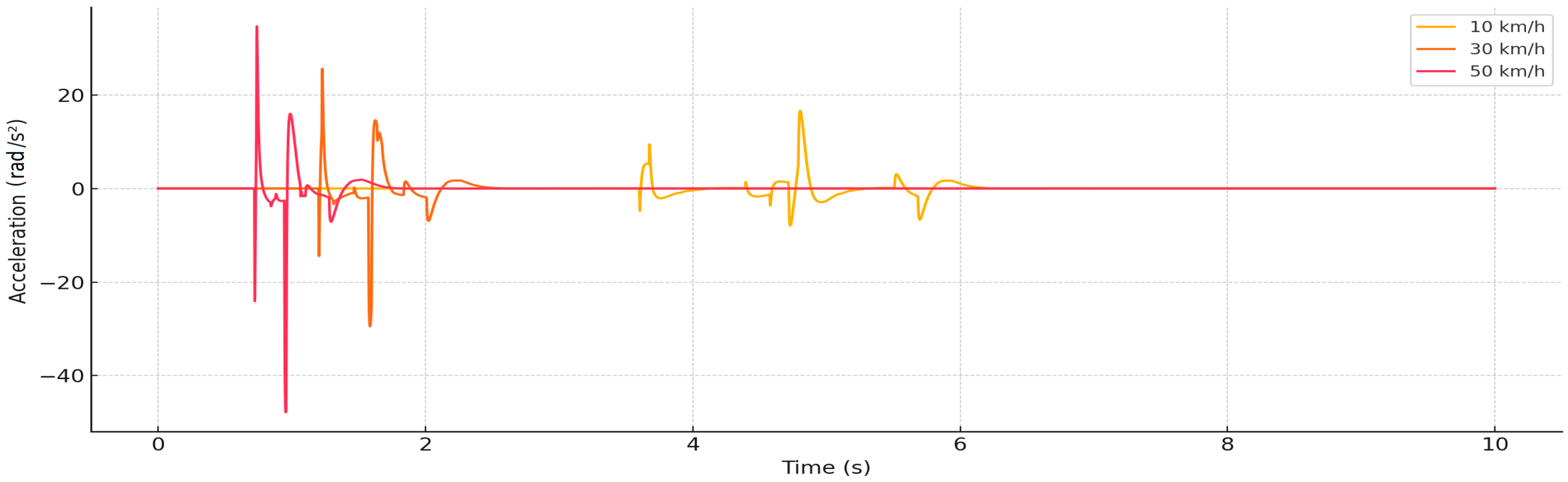
The analysis of
Figure 4 allows us to assess the dynamic response of the head to vertical mechanical shocks and vibrations when the vehicle travels over road irregularities at different speeds. The analyzed parameter—angular acceleration—is an important biomechanical indicator, as it reflects the rotational movement of the head around the neck joints, which can cause potentially dangerous loads on the neck structures and brain, especially during impact.
The main trend observed in the graph is that with increasing vehicle speed, the peaks of angular acceleration become more intense and more concentrated in time. At a speed of 10 km/h, the angular acceleration of the head reaches about ±20 rad/s2, but when the speed is increased to 30 km/h and especially 50 km/h, correspondingly higher accelerations are recorded—exceeding even ±40 rad/s2. This relationship indicates a direct link between rising speed and enhancement of the angular dynamic response. Increasing speed also makes it clear that the beginning of vibrations in the graph moves to an earlier time, which makes sense given that contact with the road surface happens earlier.
Head biomechanics principles expose the fundamental cause–effect link here: the neck, which serves as a flexible interface between the body and the head, transmits the impact starting from the vehicle chassis via the body. Due to its mechanical properties, the neck not only allows the head to rotate, but also creates a resonant response in certain situations. At higher speeds, the duration of the impact becomes shorter and its intensity increases—this means that the impact becomes impulsive and therefore more difficult to effectively suppress. Such a phenomenon causes greater angular acceleration in the head area, which in turn increases the risk of damage to the head and neck structures.
Angular acceleration in the head is directly proportional to the speed of the vehicle, and thus the danger of vibrations. Increasing angular acceleration means a higher head torque, which is important from both a comfort and safety perspective. This is especially relevant when assessing the comfort of movement, the risk of injuries and the effectiveness of biomechanical protective measures (e.g., head restraints). For these reasons, the angular response of the head should be assessed as one of the main parameters in transport ergonomics and passenger health protection.
Analyzing
Figure 5, a clear trend is observed: higher speed causes significantly higher vertical acceleration, and impacts become short-term but intense. At 50 km/h, a sudden impact with a peak exceeding 20 m/s
2 is recorded, which occurs in ~0.8 s. At 30 km/h, the impact is also expressed as a clear peak at ~1.4 s, but the amplitude reaches about 17 m/s
2. At 10 km/h, the acceleration is of longer duration but of lower intensity—peaks reach up to 7–8 m/s
2. These differences indicate that the neck responds to the ratio of vibration duration to frequency, and with increasing speed, the impact becomes more impulsive and more difficult to suppress. Physiologically, the tissues of the neck—muscles, ligaments, vertebrae—have a certain elastic response. Slower vibrations (e.g., 10 km/h) can be more dispersed through these tissues, but a sudden impact (e.g., 50 km/h) overcomes this damping capacity and causes a dangerous peak response. This results in higher speeds where the vibration duration is reduced, but the energy per unit time increases, which results in a stronger acceleration. This phenomenon is also related to resonant system properties—if the impact frequency approaches the natural frequency of the neck structure, the response increases significantly.
In addition, the distribution of impact time moments shows the influence of speed on contact with the road surface. Faster speeds—the earlier onset of impact (e.g., 50 km/h vibrations occur in the first second), which means that the entire system (including the neck) receives the load earlier and has less time to adapt. This effect can be important not only in terms of comfort, but also in terms of injury prevention—especially if the impact is repetitive or cyclical.
Figure 5 clearly demonstrates the causal relationship between increasing speed and peak acceleration in the neck, and also reveals that higher speeds pose risks not only to comfort but also to the physiological safety of the neck tissues. Such results confirm the need to carefully assess not only the head, but also the neck dynamic response during mechanical impacts in vehicle vibration studies.
The analysis of
Figure 6 shows a clear relationship between vehicle speed and peak acceleration amplitude. At 10 km/h, the maximum vertical accelerations in the body area fluctuate around 8–10 m/s
2, but as the speed increases to 30 km/h, a sharp jump to ~30 m/s
2 is observed. At 50 km/h, the maximum recorded acceleration exceeds even 50 m/s
2. These data reflect an exponential increase in the response with increasing speed, which is explained by the greater energy transferred in a shorter time and the increased frequency composition of vibrations. Due to these factors, the response in the body area becomes impulsive, and the system is no longer able to effectively absorb the impact. In addition, it is notable that the impact moment time shortens with increasing speed—at 50 km/h, the first significant impact is recorded already at 0.7 s, while at 10 km/h—only about 3.8 s. This confirms that higher speed not only enhances the mechanical response, but also accelerates the reaction of the entire dynamic chain to road irregularities.
From a biomechanical point of view, the body (usually including the pelvic, lumbar and back regions) acts as an important intermediate structure between the chassis and the upper body parts—the neck and head. The shocks transmitted in this area are usually the least damped, so the response at this point is representative of the load on the entire system. At higher speeds, when contact with the road irregularities occurs in a shorter time interval, the body receives a shock that is short in duration but very high in amplitude—which creates the conditions for damage, spinal strain or discomfort.
The cause-and-effect relationship is evident here through the interaction of system dynamics: increasing speed causes a load of shorter impulse but higher amplitude, which the body structures—muscles, discs, vertebrae—must absorb. If this impulse exceeds the system’s damping capacity, then the response increases exponentially, as seen at 50 km/h. This vibration pattern not only reduces ride comfort, but can also lead to chronic health effects of the load.
Figure 6 clearly shows that the body is one of the most stressed points in the entire biomechanical structure, especially at higher speeds. The dynamic response is strong, fast and difficult to dampen—which confirms the need to optimize the parameters of the suspension systems and ergonomic solutions in the seat area in order to reduce the body load peaks.
The general trends (see
Figure 3,
Figure 4,
Figure 5 and
Figure 6) reveal a consistent pattern: increasing speed causes a stronger vibration response, but this effect decreases disproportionately as one moves up the human body structure. For example, the vertical acceleration in the body area at 50 km/h exceeds 50 m/s
2, in the neck it reaches 20 m/s
2, and in the eye area—only 2–3 m/s
2. This effect is determined by the ability of the biomechanical structure of the human body—the spine, chest, neck and head—to absorb and dampen mechanical waves. The higher the vibration rises through the body, the more it is damped due to the elasticity of the tissues, muscle tension and flexibility of the joints.
An exceptional observation arises when analyzing the angular acceleration of the head. Although the vertical acceleration in the eye area decreases with increasing speed, the angular acceleration in the head—especially at 50 km/h—reaches dangerously high values (over ±40 rad/s2). This shows that high-frequency short pulses transmitted through the body do not cause strong linear acceleration in the head area, but induce intense rotational motion, which is physiologically even more dangerous—especially due to whiplash-type injuries or possible effects on the vestibular system.
Vertical accelerations in the neck area show an intermediate effect—here the shock wave is still strong, but clearly smaller than in the body. The neck, as a connection between the body and the head, receives both the vibration part and the beginning of the angular loads, therefore it becomes a biomechanically vulnerable zone. At high speeds, the structure of the neck is affected by both vertical and bending forces—this indicates its essential role in the process of mechanical energy transmission and damping.
It is also important to note the time component: the higher the speed, the earlier the onset of the impact, because the vehicle reaches the road unevenness faster. All components reflect this synchronously—the impact response is recorded at an earlier moment with greater intensity.
When analyzing all four graphs in an integrated manner, it becomes obvious that the human biomechanical structure behaves as a complex damping system, in which each segment has a different response depending on the nature of the vibration. At low speeds, the response remains low-frequency, slow and is damped more effectively. At higher speeds, short-term, intense waves are generated, which pose a threat not only to comfort but also to physiological safety—especially to the neck (linear acceleration) and head (angular acceleration). Such analysis emphasizes the need to assess not only amplitude parameters, but also the frequency and temporal structure of vibrations when designing ergonomic and safety solutions.
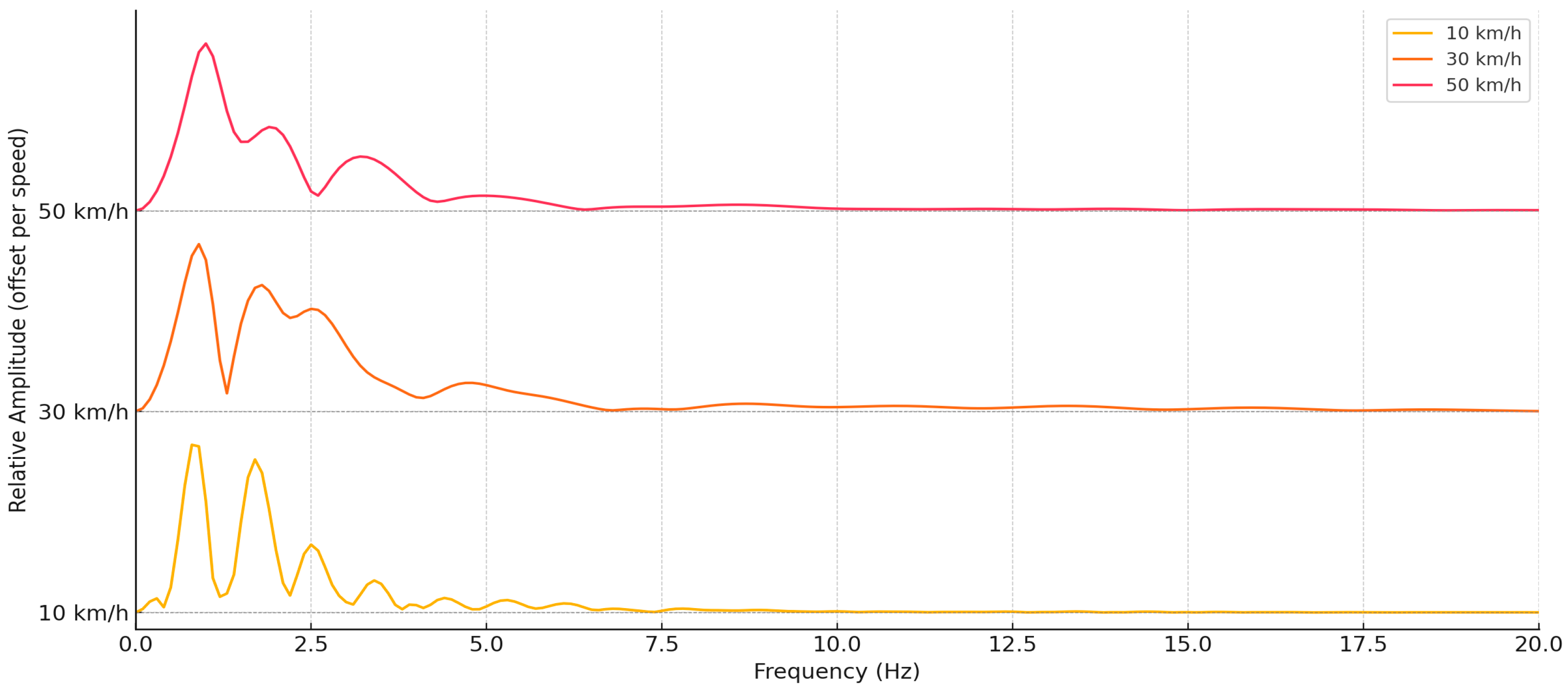
Figure 7 shows that the modal frequency range remains very similar at all speeds: the main peak frequencies are concentrated in the range from 1 Hz to 4 Hz, and components higher than 5 Hz become significantly suppressed. This suggests that the natural frequency of the system in this area is low, and the dominant resonant components appear in the low-frequency range characteristic of the human head–neck–vision system.
As the speed increases, a significant transformation of the amplitudes is observed: at 10 km/h, pronounced but narrower modal peaks are observed, while at 30 km/h and especially at 50 km/h—the curve becomes more diffuse, with more widely spread oscillations and a higher total amplitude value. This reflects the energetic expansion of oscillations in the frequency domain with increasing speed, when shorter and more intense pulses create a wider frequency spectrum.
It is important to note that although increasing speed causes an increase in amplitude, the relative shape of the response is very similar at all speeds. This confirms that the system itself (head, eyes and connecting tissues) has stable resonant properties that do not depend on the magnitude of the load, but only on the structural mechanics.
The causal relationship here manifests itself through the transformation of the dynamic input load: at higher speeds, the vehicle generates an impulse vibration wave that enters the human biomechanical system. Although this wave maintains the same modal structure, its energy becomes higher and the frequency spread is wider. As a result, the response in the eye area becomes not only stronger, but also more dispersed on the frequency scale, which may have implications for comfort, visual fixation or visual stability in dynamic conditions.
According to modal analysis, the eye–head system exhibits a velocity-independent modal response in the 1–4 Hz band. While these frequencies are relatively unaffected by slowing down, the visual system and the biomechanics of the head and neck are also affected by the increased concentration of energy at higher speeds. To enhance the comfort of drivers and passengers, the results are essential for improving ergonomic design, optimizing car seats, and fine-tuning suspension systems.
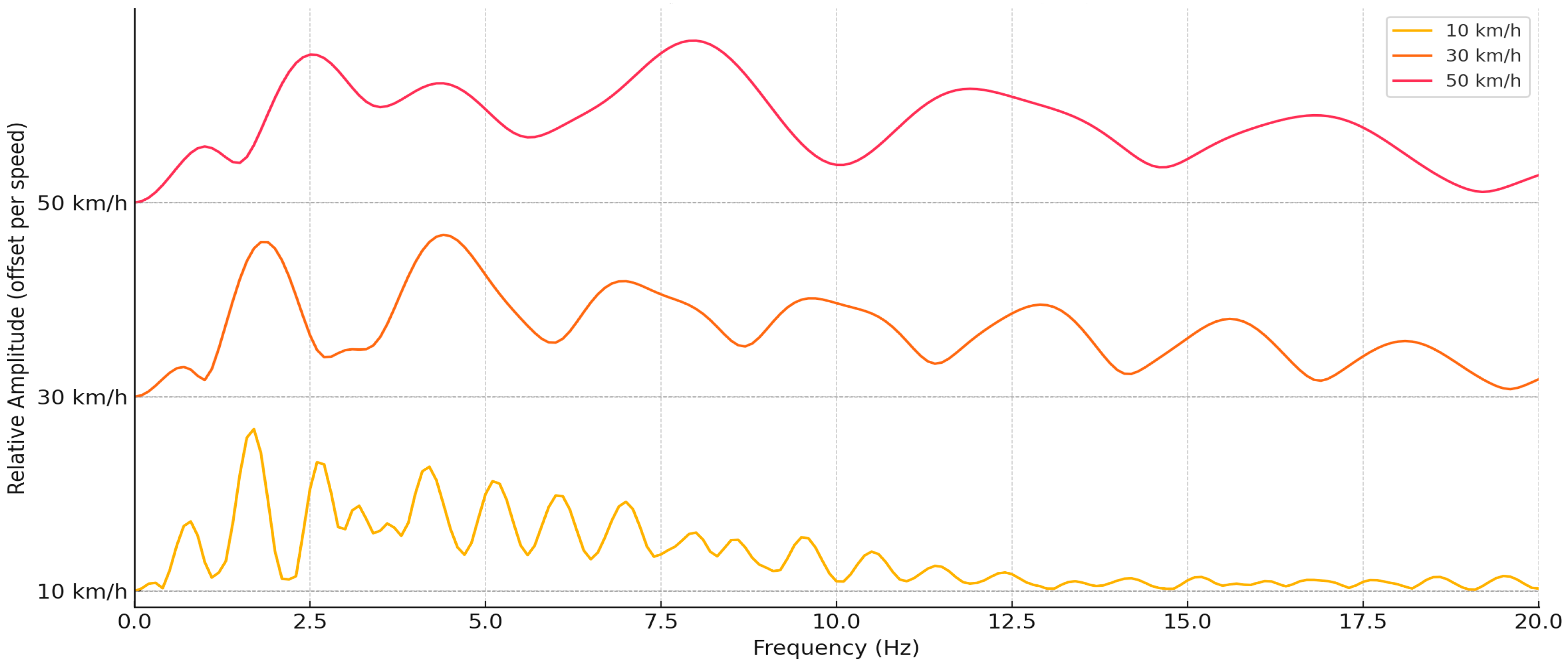
Figure 8 shows that the structure of modal frequencies remains stable at all speeds: the main responses are concentrated from 2 Hz to 9 Hz, and the most prominent peak frequencies are concentrated at 3–4 Hz, 6–7 Hz and 9–10 Hz. Such frequencies coincide with the resonant frequencies of the human head–neck system described in the literature. They reflect the natural frequencies at which the head responds most strongly to the transmitted mechanical wave. With increasing speed from 10 to 50 km/h, not only an increase in amplitudes is observed, but also their dispersion in the frequency domain. At 10 km/h, the amplitudes are more pronounced only at lower frequencies (~2–4 Hz), but at 30 and especially 50 km/h the response is extended to 12–15 Hz. This indicates that at higher speeds, the system response becomes more complex, including not only the main modal frequencies, but also higher harmonic components. The increase in the impulse force in the frequency domain links this phenomenon: the more frequencies it excites, the shorter and more powerful the input wave.
The energy transmission of intensity across the biomechanical system reveals the causal link here. At higher speeds, more impact energy is transmitted through the spine and neck to the head. As a result, the head begins to vibrate not only at its natural frequency, but also with additional resonant components, causing a broader frequency spectral response. Such a response increases the overall vibration effect, which can cause discomfort, visual stability disorders or vestibular apparatus overstimulation.
In addition, it is worth noting that although the amplitudes increase with speed, the locations of the modal peaks remain constant. This suggests that the system’s structural characteristics—mass, stiffness, damping—stay constant, hence validating the stability of the model and the modal analysis’s dependability.
All things considered,
Figure 8 shows that the frequency structure has a significant impact on the human head response; as speed rises, the head reacts not just more forcefully but also across a broader frequency range. Especially with regard to head injury prevention and ergonomic optimization of driving circumstances, this information is absolutely necessary not only in comfort but also in safety assessments.
The modal analysis allows us to identify the frequencies at which a system (in this case, the human neck) resonates or responds maximally to an external source of vibrations (see
Figure 9).
Visually, it is seen that the main modal frequencies in the neck region are concentrated in the range from 1 to 6 Hz, regardless of speed. This indicates that the neck, as a biomechanical link, is characterized by a relatively constant structural response and has natural frequencies in this zone. However, as the speed increases, the amplitude distribution changes: at 10 km/h, the curve is clearly articulated with pronounced modal peaks, while at 30 and especially 50 km/h the response becomes more diffuse and flatter. This difference can be explained by the transformation of the high-energy impulse load into the frequency domain. At lower speeds (10 km/h), the vehicle’s response to road roughness is of longer duration and lower amplitude, so the neck resonates in clearer shapes—the response reflects typical biomechanical modal frequencies. At higher speeds (especially 50 km/h), the pulse becomes shorter and the energy density is higher—this causes frequency dispersion, when more frequency components become active, and the modal peaks flatten out.
It is also significant to note that although the amplitudes are relative, their shape shows a systematic resonant damping that changes with the intensity of the load. At higher speeds, the neck loses clear resonant peaks, which could be related to the activation of the neuromuscular response or structural nonlinearity, when the tissues no longer behave as a linear damping system.
The causal relationship in this analysis is manifested through the transfer of mechanical wave energy. As the speed increases, the pulse becomes more concentrated in time, which increases the frequency distribution of the energy. The neck, being between the body and the head, receives both vertical and angular loads; therefore, its modal response becomes sensitive to both the directionality of the load and its frequency composition. This confirms that the neck is the most biomechanically risky area—it not only transmits vibrations to the head, but also experiences complex modal load patterns itself. In summary, the modal analysis of the neck shows that this part of the body has a fairly stable resonant response in the low-frequency range, but with increasing speed, the response structure transforms—from sharp peaks to broad waves. This indicates an excess of energy for higher frequencies, and at the same time a potentially greater biomechanical risk, which can affect both comfort and neck health.
Figure 10’s analysis allows us to assess the structure of the frequencies at which the body responds most strongly to vibrations and the changes associated with increasing speed.
The results of the modal analysis show that the main resonant frequencies in the body area occur in the range from 1 to 6 Hz, and at all speeds, dominant points around 2.2 Hz, 3.8 Hz and 5.5 Hz emerge. These frequencies correspond to the low-frequency mechanical response, which is characteristic of large and relatively poorly damped structures, such as the human torso or pelvis. These areas have a greater mass and lower stiffness than, say, the head or neck, so they resonate more in the low-frequency range.
As the speed increases, a clear amplification of the modal response is observed—at 10 km/h the amplitudes are clear, but lower and narrower, while at 30 and 50 km/h the response becomes wider, more diffuse and with sharper peaks. This is explained by the fact that at higher speeds, the vibrations are more intense and more impulsive, which leads to a larger amount of frequency energy. Therefore, the response in the system activates more frequency components and causes a complex dynamic response.
Regular maintenance of the location of the modal peaks is also observed: their positions do not change depending on the speed. This indicates that the biomechanical properties of the body—mass, stiffness, damping—remain constant, and the speed changes only the intensity of excitation, but not the resonant characteristics. Such a system corresponds to the model of a linear mechanical system, to which Fourier analysis can accurately reveal its structural frequencies.
The causal relationship in this analysis is manifested through the dependence of the amplitude and frequency of the mechanical wave on the speed. As the speed increases, the impact caused by road irregularities becomes more intense, so energy is transferred not only at low but also at higher frequencies. As a result, more modal modes are excited—their amplitude increases, and the response structure becomes less localized on the frequency scale. This phenomenon biomechanically means that the body region, especially the spine and pelvic segments, receives a higher amount of vibration, which must be absorbed by passive tissues (muscles, discs, fascia).
In summary, the body’s modal response is stable in terms of frequency, but sensitive to speed increases in terms of amplitude and frequency dispersion. This emphasizes the need not only to limit the intensity of vibrations in the vehicle suspension, but also to design ergonomic seating systems that would maximally dampen resonant frequencies in the human torso structures, especially when traveling at higher speeds.
The four modal figures (see
Figure 7,
Figure 8,
Figure 9 and
Figure 10) presented represent the response of the upper part of the human body’s biomechanical chain to mechanical vibrations: from the torso (body) through the neck (neck) and head (head) to the point of vision (eye) (eye with head). All these components are biomechanically interconnected, but each of them has its own mass, stiffness and damping characteristics, due to which their modal response to vibrations is different.
The Body region exhibits clear and strong modal peaks in the frequency range from 1 Hz to 6 Hz, especially at higher speeds. This indicates that the torso, with its large mass and lower damping, resonates most in the low-frequency range, especially if the vibrations arise from seat or chassis dynamics. Higher speeds lead to an increase in amplitudes and an expansion of the modal structure to higher frequencies (up to ~10 Hz), which means that the torso acts as a primary source of vibrations for higher parts of the body. The neck acts as a biomechanical connection between the torso and the head, and its modal response also appears in the frequency range from 1 Hz to 6 Hz, but the amplitudes are smaller and the peak structure is clearer and more localized. At higher speeds, the neck responds to a wider frequency spectrum, but the amplitudes remain smaller than in the body, indicating partial vibration damping.
The head response is more complex—the amplitude of the oscillations continues to increase with speed, but the most important change is the broadening of the modal frequencies to ~15 Hz, especially at 50 km/h. This indicates that the head is sensitive not only to the fundamental resonant frequencies (2–6 Hz), but also to higher frequencies, which are activated by stronger input impulse loads. Such broadening of the frequency structure is of fundamental importance from a safety point of view—as speed increases, the head response becomes less and less damped, and angular accelerations can cause additional loads on internal structures (e.g., the brain or vestibular apparatus).
The eye with head response is significantly smaller in amplitude, but the locations of the modal peaks remain aligned with the head response. This suggests that the eye region, which is at the top of the biomechanical chain, is a well-damped system, but still reflects the modal character of the head. Resonant frequencies (~1–4 Hz) remain dominant at all speeds, but the amplitudes grow more slowly than in other segments, indicating that the vibration energy in the higher structures is absorbed or reflected through the neck–head interface.
Comparing all four modal figures (see
Figure 7,
Figure 8,
Figure 9 and
Figure 10), it becomes obvious that the human body behaves as a frequency-damping system, in which energy propagates from the bottom to the top, with gradually decreasing amplitudes. However, as speed increases, the vibration spectrum broadens, which increases the density of modal vibrations and the systemic response. Such results are particularly important in the fields of transport ergonomics and safety—they allow us to identify the body segments that receive the greatest load and suggest directions for optimizing vibration isolation at different points of the human body.
4. Discussion
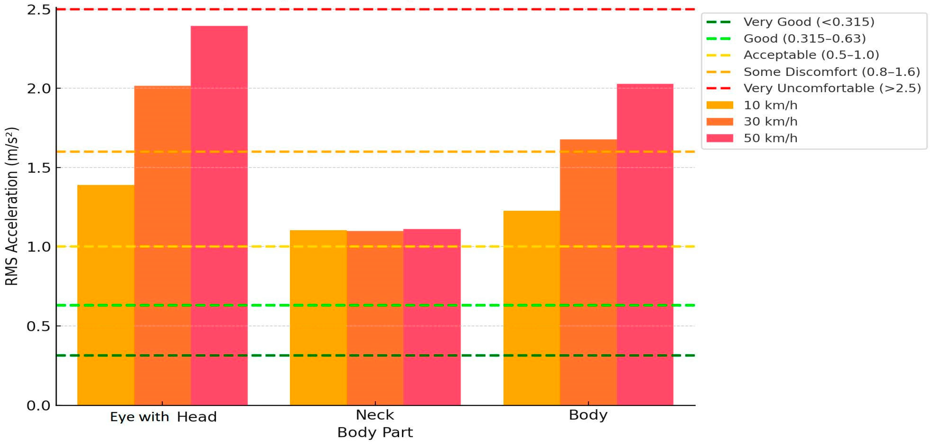
The analysis in
Figure 11 was performed according to the ISO 2631-1 comfort assessment methodology [
28], and the additional horizontal lines reflect the standardized RMS comfort limits, which allow classifying the effects of vibrations according to the intensity of the impact. This allows us not only to quantitatively assess the intensity of vibrations, but also to draw qualitative conclusions about the comfort state and risks to human health. First of all, a clear increase in RMS acceleration can be observed in all body areas with increasing speed. However, this increase is not uniform between segments. In the eye with head area at 10 km/h, the RMS value is about 1.4 m/s
2 and falls into the “Some Discomfort” zone (0.8–1.6 m/s
2), but at 50 km/h it exceeds 2.4 m/s
2, approaching the ISO “Very Uncomfortable” limit (>2.5 m/s
2). This indicates that the head area, especially related to visual stability, is very sensitive to higher speeds.
In the neck area, the situation is essentially stable: RMS values remain around 1.1 m/s2 at all speeds, falling into the “Acceptable” zone (0.5–1.0 m/s2) or close to the “Some Discomfort” threshold. This allows us to conclude that the neck has a better damping mechanism, possibly due to muscle tension and mechanical flexibility, and its dynamics are less dependent on the transport speed.
In the body area, RMS values also increase consistently: from ~1.2 m/s2 at 10 km/h to more than 2 m/s2 at 50 km/h, crossing the “Some Discomfort” zone and approaching “Uncomfortable”. Such dynamics reflect a high concentration of vibrations in this area, since it is the first point of contact with the vibration source (the seat).
Analyzing causal relationships, it can be stated that increasing speed causes increasing mechanical energy transfer from the chassis to the human body, which directly increases RMS values. However, it is notable that the rate of growth of the response differs: the head responds disproportionately more, and the neck—the slowest. This allows us to judge different biomechanical characteristics: the head—with limited damping, the body—with a large amount of energy, and the neck—as a stabilizing mediator.
Figure 11 shows a clear influence of speed on the comfort state in the structures of the human body. The ISO 2631 comfort limits allow not only to classify the condition of each body area, but also to justify safe speed limits, taking into account vibration parameters. It is especially important to pay attention to the head, which, if the 2.5 m/s
2 RMS limit is exceeded, is not only subject to discomfort, but also to the risk of functional damage related to the vision or vestibular system. This indicates the need to make decisions on vibration damping measures—both structural (e.g., seat cushioning) and organizational (speed limits)—especially at higher transport speeds.
First of all, it is important to note that each part of the body has a different sensitivity to vibration, so the speed values required to achieve certain comfort levels vary significantly (see
Figure 12). The body (torso area) reaches the “Very Uncomfortable” level (~2.5 m/s
2 RMS) already at ~65 km/h, and “Uncomfortable”—at just ~50 km/h. This shows that the body is the most stressed biomechanical structure in the case of vertical vibrations, since it is the first to contact the seat and receives the primary mechanical energy from the vehicle chassis.
Meanwhile, in the eye with head area, the “Uncomfortable” level is reached only at ~80 km/h, and “Very Uncomfortable” is only above 95 km/h, which shows that the vibration intensity decreases significantly as it rises through the body’s biomechanical chain. This trend reflects the damping capacity of the human body—the head and eyes, as the final energy receivers, receive only a part of the mechanical energy that was dissipated and absorbed through the spine, pelvis, and neck.
The neck stands out as a biomechanically more stable link: it requires speeds above 130 km/h to reach the “Very Uncomfortable” level, and around 110 km/h to reach the “Uncomfortable” level. This can be explained by two reasons: (1) the neck acts as a biomechanical shock absorber between the head and torso, (2) its RMS response is lower due to its lower mass and active muscular compensations.
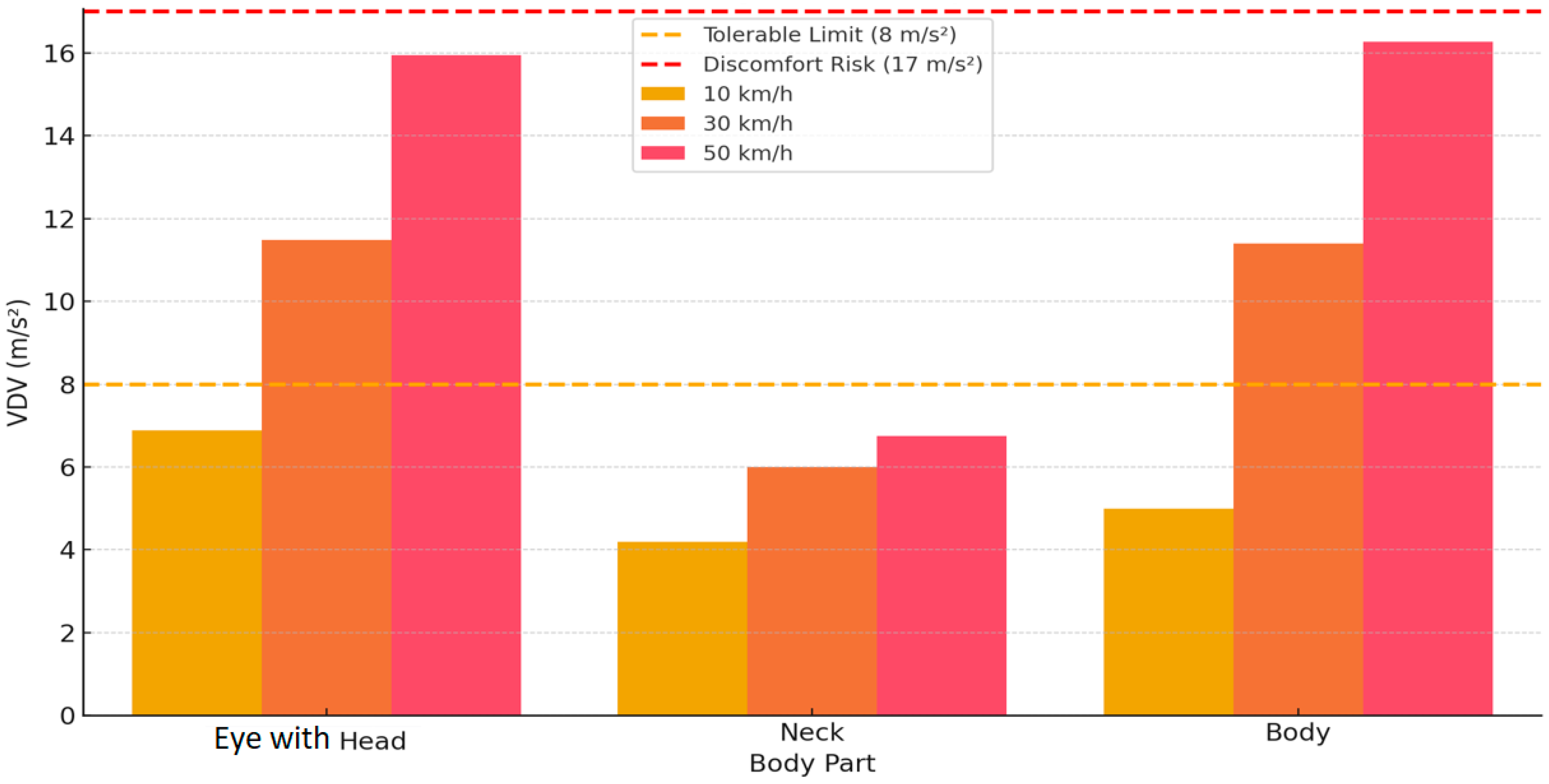
Figure 13 presents an analysis of vibration dose value (VDV) indicators by body part and vehicle speed (10, 30 and 50 km/h), based on the comfort limits of the ISO 2631 standard. VDV, measured in m/s
4, is an indicator of the accumulation of vibration effects, particularly sensitive to short-term, impulsive shocks, and is therefore well suited to assess the discomfort caused by a vehicle in dynamic conditions. The graph shows the two main ISO 2631 limits: 8 m/s
4—the tolerable limit and 17 m/s
4—the risk of discomfort/injury. When analyzing the results, a clear trend is observed: higher speed causes exponentially increasing VDV in all body areas. All body sections stay below the 8 m/s’ criterion at 10 km/h, indicating that the vibration load stays acceptable. At 30 km/h, both the head and body exceed 8 m/s
4, nearing the discomfort zone; at 50 km/h both these areas exceed the 17 m/s
4 barrier, entering the risk zone where vibration exposure is already thought to be detrimental to long-term health.
The body segment reaches its highest VDV—over 16 m/s4 at 50 km/h, which is consistent with previous RMS analysis results that showed that the torso is the main energy accumulator in the vibration chain. This result confirms that the torso experiences both frequency and impulse loading—making the VDV at this point extremely sensitive to speed changes.
The head response is also significant—at 50 km/h, the VDV approaches the discomfort limit. This means that even if the RMS accelerations in the head area are not extreme, short-term impulse shocks accumulate quickly enough to cause the head to vibrate with a higher health risk. In the neck area, the VDV remains the lowest and most stable at all speeds, indicating effective biomechanical damping of the neck, which dampens both linear and impulse vibrations.
The causal relationship between speed and VDV shows that the growth of VDV is exponential, not linear. Especially if the vibrations are brief and intense—as is the situation while driving over acute road defects or at high speed—even a little rise in speed can greatly raise the mechanical impact dose. Since the body and head regions are where this impact is most notable, they are given top priority to guarantee comfort and safety.
The VDV analysis reveals that speed is a critical factor not only in terms of RMS, but also in terms of vibration dose accumulation. It complements the RMS assessment by identifying those situations where even short-term but intense impacts can be physiologically dangerous. Therefore, ergonomic measures should be aimed at mitigating these impulse loads, especially in areas of the body and head where the cumulative vibration value exceeds the ISO safety limits.
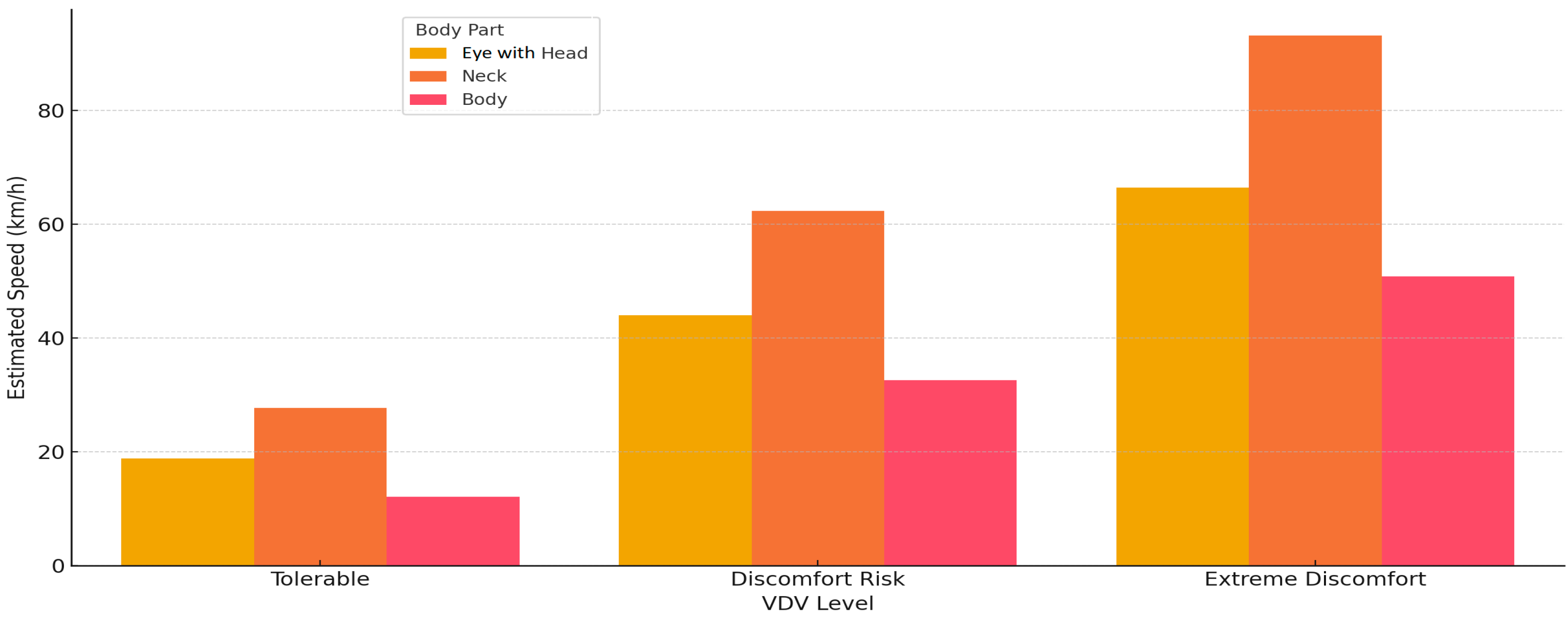
Figure 14 visualizes the calculated transport speeds required to reach the ISO 2631 VDV thresholds in three different areas of the human body—eye with head, neck and body. The horizontal axis shows the three comfort levels according to the ISO classification: “Tolerable”, “Discomfort Risk” and “Extreme Discomfort”, and the vertical axis shows the corresponding speed in km/h that would cause a specific VDV level. This analysis is based on empirical data and modeled by linear regression, allowing us to predict the moment when the vibration dose exceeds physiologically or ergonomically acceptable levels.
The general trend is clear: the higher the part of the human body, the higher the speed required to reach the critical VDV thresholds. This reflects the damping capacity of the human body’s biomechanical chain—vibrations, propagating from the bottom (through the seat) up (body → neck → head/eye), gradually weaken due to the elastic properties of the tissues, muscle activity and joint interactions.
The body segment is the most stressed: it only takes ~33 km/h to reach the “Discomfort Risk” level, and “Extreme Discomfort” already at 50 km/h. These data confirm that the torso area is most exposed to short-term impacts, the energy of which accumulates quickly, and the VDV indicator reaches the highest values here. This is related to both the proximity to the vibration source (seat), and to the greater mass and lower damping efficiency.
The eye with head area reaches the “Discomfort Risk” limit only at about 45 km/h, and “Extreme Discomfort” above 65 km/h. Although these speeds are higher than those of the body, they are still not far away—this indicates that the head-vision system, although suppressed by the biomechanics of the neck, still experiences a significant vibration effect under intense mechanical loads. This is especially important when assessing visual stability, head discomfort and functional risks (e.g., balance and attention disorders).
The neck stands out as a biomechanically resistant system—VDV reaches a “Discomfort Risk” level only above 60 km/h, and “Extreme Discomfort” around 95 km/h. These results confirm that the neck, as a combined mechanical shock absorber, effectively dampens both low and high-frequency vibrations, especially if they are impulsive. However, as can be seen from previous angular acceleration analyses, even if VDV is low, this does not necessarily mean that biomechanical risk to the neck does not exist.
The causal relationship in this graph describes how speed determines the rate of vibration energy accumulation. In the case of short but intense impacts, the growth of VDV becomes exponential—as a result, even a small increase in speed exceeds the comfort limits. In addition, it is seen that the thresholds of all body areas are reached at different speeds, therefore a universal speed limit is not optimal for passenger comfort and safety—it must be differentiated according to the biomechanical response.
While the head and neck show more biomechanical resistance,
Figure 13 shows the torso as the most vulnerable location to VDV buildup. Ergonomically, this means that vibration reduction measures—such as seat design and shock absorbers—should be concentrated mostly on preserving the thoracic area, while guaranteeing that vibration energy does not unduly travel to top structures such as the neck or head. These ideas are useful in the implementation of comfort criteria, passenger safety modeling, and transportation design.
In summary, it can be stated that masses, stiffness coefficients, damping values, and segment dimensions used in our simulations were derived from a synthesis of prior biomechanical models, particularly those found in Akbari and Margolis [
27], Sun et al. [
31], and Múčka [
26]. For example, the neck and torso stiffness values are modeled as nonlinear springs with coefficients that match ranges validated in seated passenger response studies using experimental setups and mannequins.
While the precise structure of our model is novel—especially in combining nonlinear damping, angular acceleration effects, and frictional interactions—we compared our simulation outputs with those reported in the literature:
Considering the above information, it can be stated that these parallels strongly suggest that our model reproduces the essential dynamic behaviors observed in real-world biomechanical studies, despite not replicating any single prior model exactly.
To further support the plausibility of our model, we used the ISO 2631-1 standard as an objective external validation framework. The ISO standard provides defined thresholds for comfort, discomfort, and health risk based on RMS and VDV acceleration values measured at various points of the human body. Our simulation results were evaluated against these limits, and the transitions observed across speed increments (from “Some Discomfort” to “Very Uncomfortable” and “risk zone”) fall exactly within the expected progression.
For instance, the torso segment crossed the “Very Uncomfortable” VDV threshold (>17 m/s4) at approximately 50 km/h, while the head approached this level but remained under it, in line with the understanding that the torso absorbs more vibrational energy due to its proximity to the seat–vehicle interface. These findings support the idea that our model behaves in a biomechanically consistent manner under realistic operating conditions.


 ,
, 


