Article

Study on Steam Excitation Forces Induced by Tip Seal Leakage Flow in Steam Turbines

1
School of Energy and Power Engineering, Northeast Electric Power University, Jilin 132012, China
2
State Grid Songyuan Elect Power Supply Co., Songyuan 138000, China
*
Author to whom correspondence should be addressed.
Machines 2025, 13(6), 518; https://doi.org/10.3390/machines13060518
Submission received: 26 April 2025 / Revised: 10 June 2025 / Accepted: 11 June 2025 / Published: 13 June 2025
(This article belongs to the Section Turbomachinery)

Abstract

:
This study aims to elucidate the mechanisms by which tip seal leakage flow induces steam excitation, thereby enhancing the operational safety of steam turbines. Using numerical simulations, it investigates the detailed characteristics of the flow field in the turbine tip seal cavity. By introducing Boundary Vorticity Flux (BVF) into the tip seal flow field, this research explores the relationship between leakage vortex structures in non-uniform flow fields at the blade tip and the resulting steam excitation forces. The results demonstrate that, during eccentric rotor operation, the extent and intensity of vortices within the seal cavity vary, lead to changes in the BVF distribution along the shroud surface, which in turn alter the tangential forces and induce variations in lateral excitation force at the blade tip. Additionally, the non-uniform flow in the tip seal clearance induces circumferential pressure variations across the shroud, leading to adjustments in radial excitation force at the blade tip.

1. Introduction

The leakage Flow within steam turbine tip seals is characterized by high-intensity vortex systems, separations, and jet flows [1,2,3]. When eccentricity occurs in the turbine rotor’s operation, the leakage flow at different clearance heights undergoes complex spatial and temporal evolution. This results in uneven circumferential pressure distribution within the tip seal, potentially generating steam excitation forces that threaten rotor system stability. Extensive empirical studies have confirmed a different relationship between the tip seal leakage flow field and clearance flow excitation forces [4,5,6,7]. Investigating the excitation-inducing mechanisms of the uneven tip clearance flow field in large steam turbines is essential for understanding the generation of tip clearance excitation forces. Furthermore, this knowledge provides valuable insights for designing turbine rotors to handle high-load, high-speed conditions, enhancing the safety and efficiency of steam turbine operation.
Numerous studies by domestic and international scholars have explored the complex variability of tip clearance leakage flows and the oscillatory behavior of induced steam excitation forces in blade tip [8,9,10,11,12]. Jeffrey [13] conducted a numerical study on the three-dimensional flow field within turbine seals, establishing relationships between sealing leakage, excitation forces, and rotor dynamic force coefficients. Zou et al. [14] explored steam excitation forces within tip shroud seals under static and dynamic eccentric conditions, highlighting the critical impact of circumferential steam velocity on clearance excitation forces. Gu et al. [15] proposed injecting steam flow in the opposite direction of rotation into the seal cavity to counteract the original circumferential motion of the tip leakage flow. Although this method showed some effectiveness, its complex implementation and operational challenges prevented its practical application. Regarding seal structure optimization, Zhang et al. [16] optimized the end-wall structure by introducing micro-blade arrays at the tip entry and the seal cylinder’s front, reducing excitation by improving pre-swirl and circumferential velocity distribution. Sun et al. [17] investigated the fluid and dynamic characteristics of pouch-type damping seals. The results indicate that the pouch-type damping seals can effectively impede the circumferential velocity of leakage flow, thereby reducing the transverse steam excitation force on the rotor and improving stability. Lang et al. [18] developed a new tiltable seal design that reduces excitation forces by self-adaptively adjusting seal block orientations to modify the flow field within the seal cavity. However, modifying the seal structure has little contribution in reducing the fluctuations in steam excitation forces.
The fluctuations In steam excitation forces are closely related to the pressure pulsations within the tip seal cavity. Rzadkowski et al. [19] measured the pressure distribution in the tip seal cavity and analyzed the relationship between steam excitation forces, rotational speed, and eccentricity using the pressure integration method. Liu et al. [20] measured the pressure fluctuation on the rotor surface at blade tip clearance by the dynamic pressure sensor on the end-wall of single row rotors, and obtained the relation between the dominant frequency of pressure fluctuation and the rotation speed. Donghyun et al. [21] employed Large Eddy Simulation (LES) to investigate the underlying mechanisms of pressure fluctuations and force variations caused by the unsteady characteristics of tip leakage vortex structures in axial turbomachinery. Li et al. [22] explored the pressure pulsation characteristics in the rotor blade tip seal cavity, examining the effect of unsteady factors on the excitation force fluctuation within the tip seal flow field. Wang et al. [23] installed dynamic pressure sensors on the rotor tip casing to capture pressure pulsation signals, demonstrating that the rotating pressure pulsations induced by tip leakage flow exhibit frequency characteristics consistent with rotor instability.
Despite these developments, the induction mechanisms between seal clearance leakage instability and steam excitation force fluctuations remain insufficiently understood. Further studies are urgently needed to explore the interaction between the evolution of leakage vortices in the tip clearance region and the excitation force pulsations. Wu and Wu [24] pioneered the boundary vorticity dynamics theory, demonstrating a strong correlation between the forces and moments exerted on an object and Boundary Vorticity Flux (BVF) of its surface. This theory provides a mechanistic explanation for the relationship between wall vorticity and aerodynamic loads. Ahmed and Yen [25] applied BVF in low-speed compressors, proposing an optimized design constrained by BVF that yielded positive results. Liu et al. [26] established a direct mathematical–physical relationship between total performance parameters of compressors and BVF, suggesting improvements in compressor design from a vortex perspective, which they later applied to gas turbine design. However, previous studies primarily employ BVF analysis for blade profile optimization and cascade aerodynamic performance enhancement. Rarely has the BVF methodology been applied to investigate the interaction between tip seal leakage vortices and steam excitation forces in turbomachinery tip seal cavities.
This study uses numerical simulation to analyze the distribution of non-uniform flow fields within turbine tip seals under rotor eccentricity, examining variations in the tip clearance-induced excitation forces. By introducing BVF into the tip seal flow field, the research explores the relationship between the evolution of leakage vortices in non-uniform flow fields and excitation forces, aiming to reveal the mechanisms through which tip clearance leakage vortex evolution induces fluctuations in excitation forces within steam turbines. The overall flow chart is shown in Figure 1.

2. Computational Model and Numerical Methods

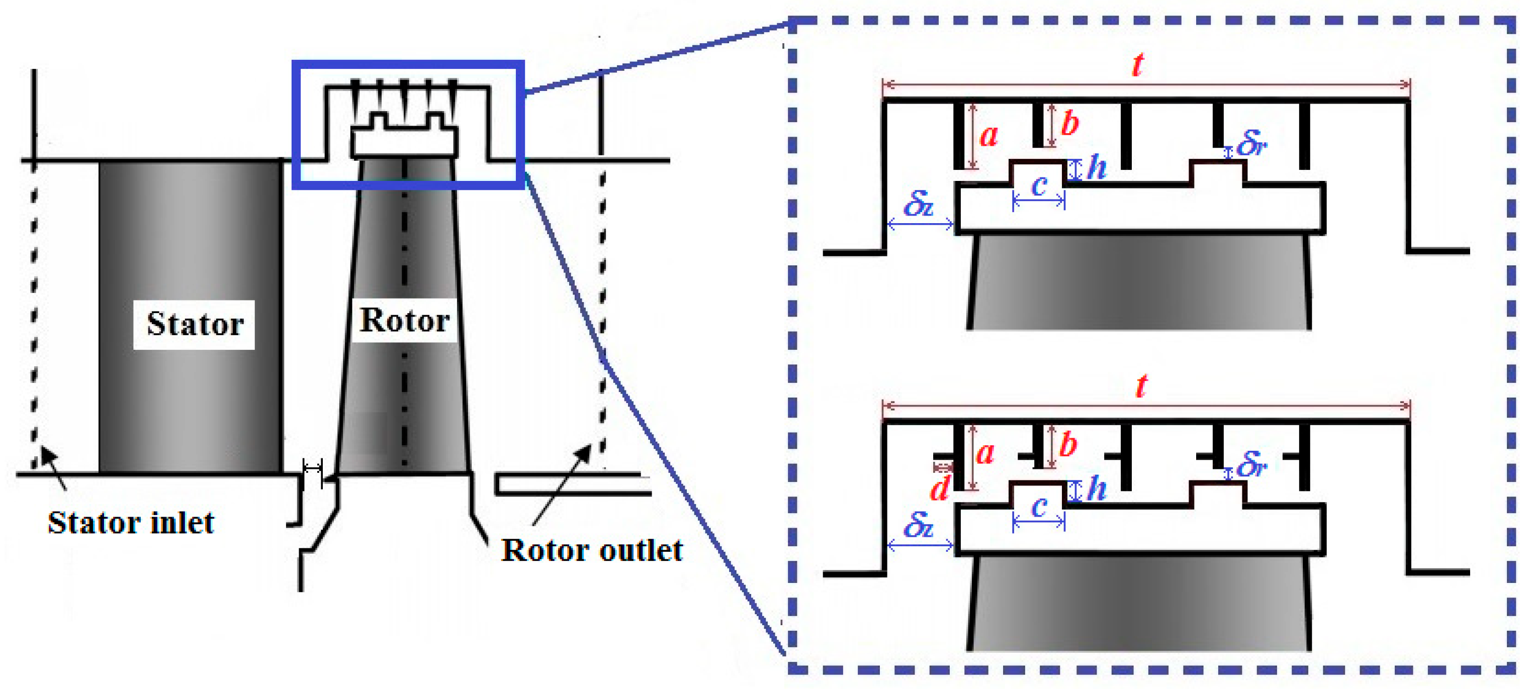
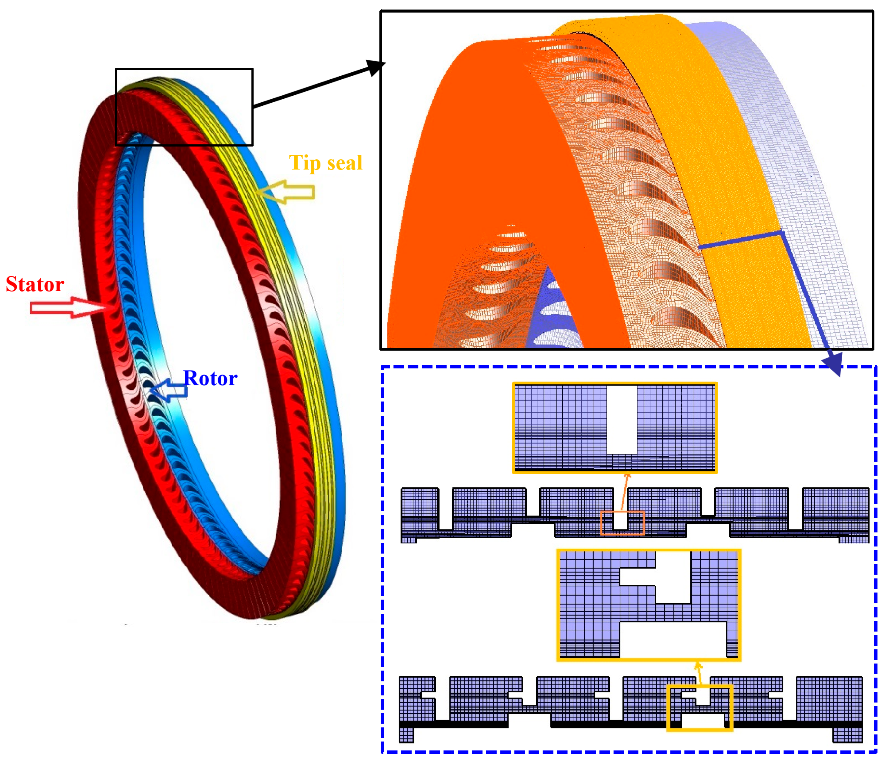
2.1. Physical Model and Computational Grid

A high-pressure stage of a 600 MW steam turbine was selected as the computational model for this study. Figure 2 illustrates a schematic of the turbine stage model, which includes the shroud, stator blades, rotor blades, and blade tip seal components. To enrich the flow field data of the tip seal and more effectively reveal the patterns of leakage-induced flow excitation, two seal structures were designed: a high-low teeth seal and a side teeth seal. The primary structural dimensions for the rotor blades and tip seal components are detailed in Table 1.
Figure 3 depicts the mesh structure for the stator blade passage, rotor blade passage, and the blade tip seal clearance. An unstructured hexahedral mesh was applied to the rotor region, with a refined mesh in the tip seal clearance area, which requires focused analysis. Additionally, localized boundary refinement was conducted in the seal teeth clearance and shroud wall regions, setting the height of the first mesh layer to achieve a y+ value of approximately 1.4 to ensure computational accuracy.

2.2. Boundary Conditions

This study utilizes Fluent 2022 R2 to simulate the three-dimensional unsteady flow field, using superheated steam as the working fluid. The reference pressure for the model is set to atmospheric pressure. The inlet boundary condition is specified as a pressure inlet with a pressure of 11.72 Mpa and a temperature of 756 K. The outlet boundary is set as a pressure outlet with a pressure of 10.9 Mpa. The surfaces of the blades, shroud, and tip seal are configured as adiabatic, no-slip, and smooth wall boundary conditions.

2.3. Numerical Methods

The finite volume method is employed for the numerical calculations, with spatial discretization using a second-order upwind scheme. The Semi-Implicit Method for Pressure-Linked Equation (SIMPLE) algorithm is used to address the coupling between velocity and pressure. Given the Shear Stress Transport (SST) k-ω turbulence model’s superior capability for simulating secondary flows in the near-wall boundary layer and blade tip region [27], this turbulence model is applied in the calculations.

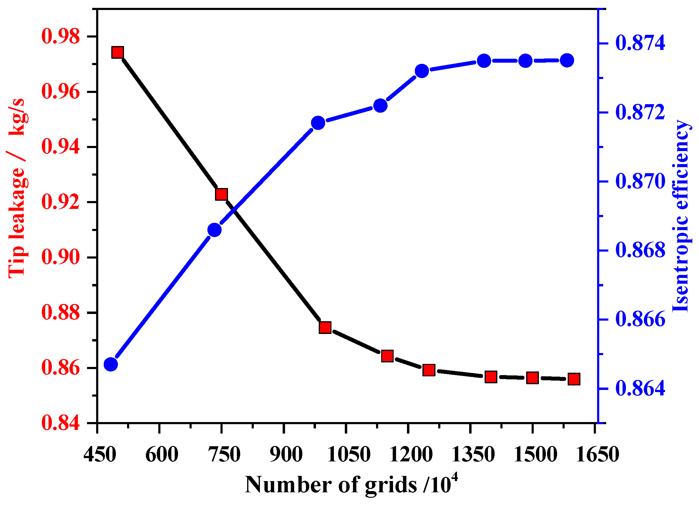
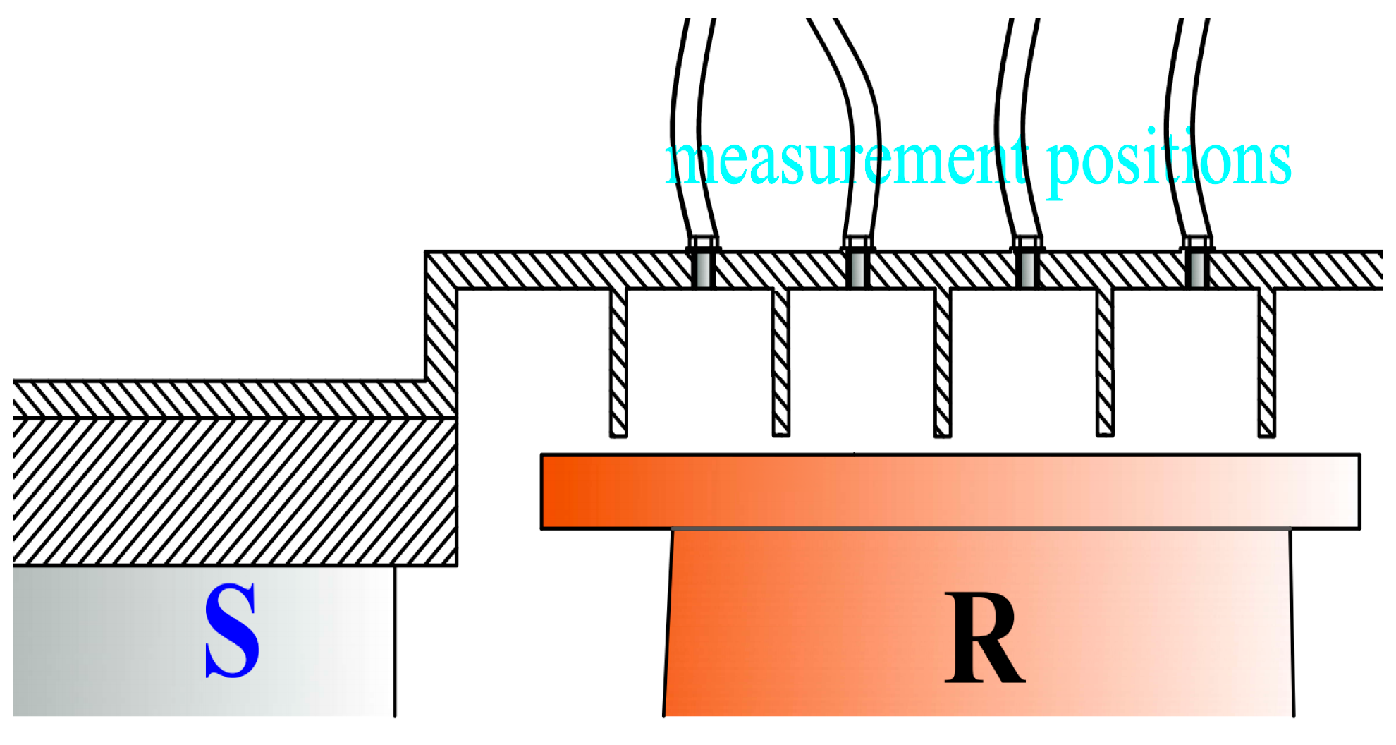
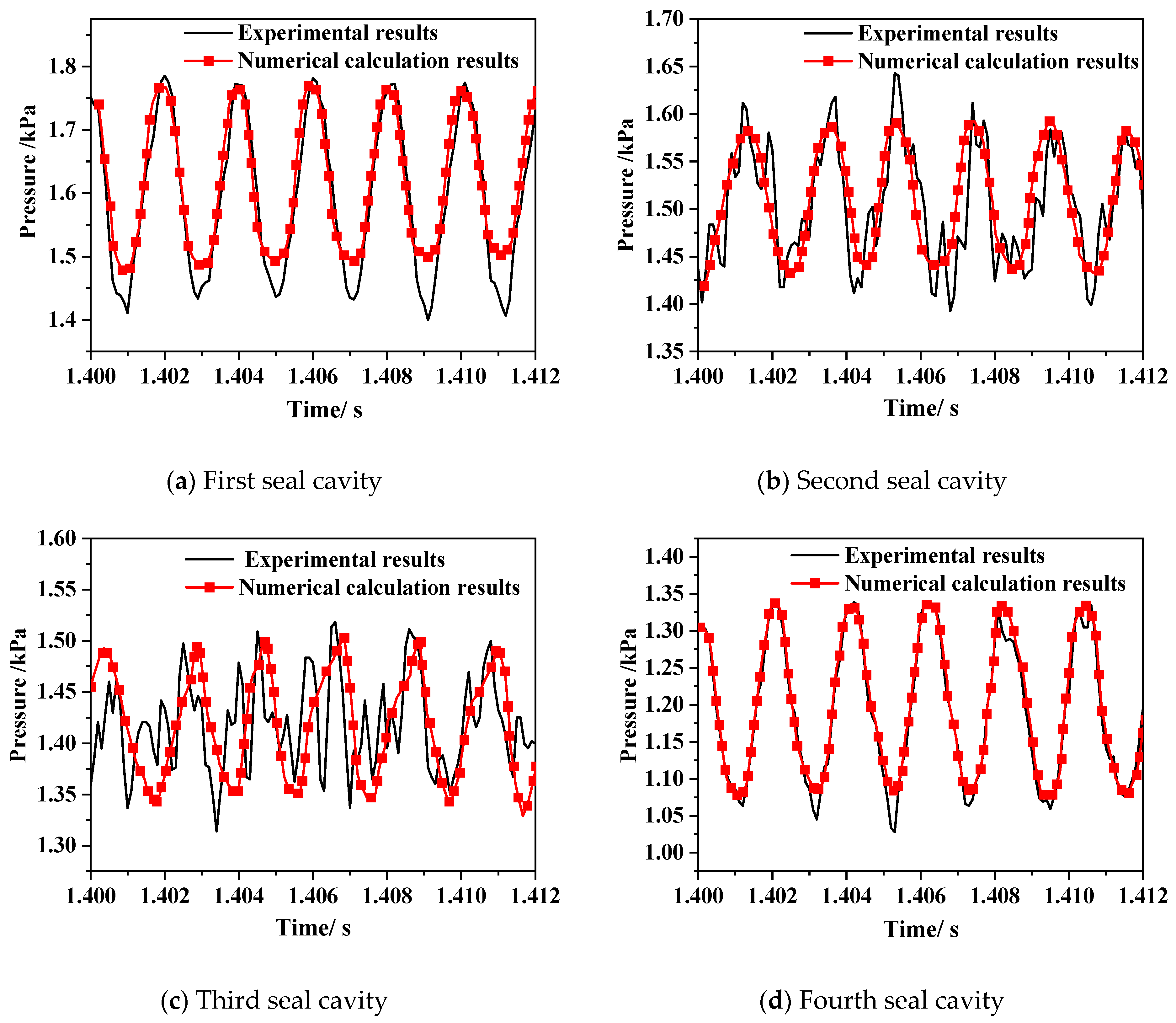
2.4. Validation of Results

To confirm that the numerical results are independent of the mesh count, two critical parameters (e.g., isentropic efficiency and blade tip leakage) were selected to verify mesh independence.
The formula for calculating isentropic efficiency is expressed as follows [28]:
η = 1 T 1 * / T 0 * 1 p 1 * / p 0 * γ 1 / γ
where p0* represents the total pressure at the model’s inlet; p1* represents the total pressure at the outlet; T0* represents the total temperature at the inlet; T1* represents the total temperature at the outlet; and γ represents the adiabatic index, which is set to 1.3 for superheated steam.
In Figure 4, when the mesh count reaches 14 million, further increases in mesh density no longer affect the computed results for blade tip leakage and isentropic efficiency, indicating that these monitored parameters are insensitive to additional mesh refinement. Therefore, the total mesh count is maintained at approximately 14 million to ensure computational efficiency and accuracy.
To verify the accuracy of the numerical calculations, an experimental setup measuring tip clearance pressure pulsation and steam flow excitation was utilized. In Figure 5, the setup consists of a centrifugal fan driving the working fluid through a stationary blade array, accelerating the flow before entering a rotating blade array. A digital pressure sensor measures the pressure in the rotating blade array and within the tip seal clearance flow field. The distribution of measurement positions within the tip seal cavity is identical to that reported in Reference [29], as illustrated in Figure 6.
Since unsteady numerical simulations can capture parameter variations over time, and the pressure within the blade tip seal is correlated with steam excitation forces, it is necessary to validate the accuracy of the unsteady numerical method in capturing pressure fluctuations inside the blade tip seal cavity. A numerical model was established using the same blade array dimensions, boundary conditions, rotating blade speeds, and working fluid as in the experiment, with the SST k-ω turbulence model for unsteady calculations. The pressure pulsation results obtained from the unsteady numerical simulations were then compared with the experimental data. Since the experimental measurements exhibited stable pressure fluctuations after 1.4 s, the validation was performed over six fluctuation cycles beyond this time point, as illustrated in Figure 7. The numerical results for the first and fourth seal cavities closely match the experimental results. However, the consistency between the numerical and experimental results is slightly weaker in the second and third seal cavities, suggesting that the experimental measurements are more sensitive to the pressure fluctuations induced by minor turbulent pulsations within the seal cavities. Overall, the numerical results align well with the experimental data, reflecting the pressure fluctuation patterns within the tip seal cavity. This indicates the reliability of the unsteady numerical calculation results.

3. Result Analysis

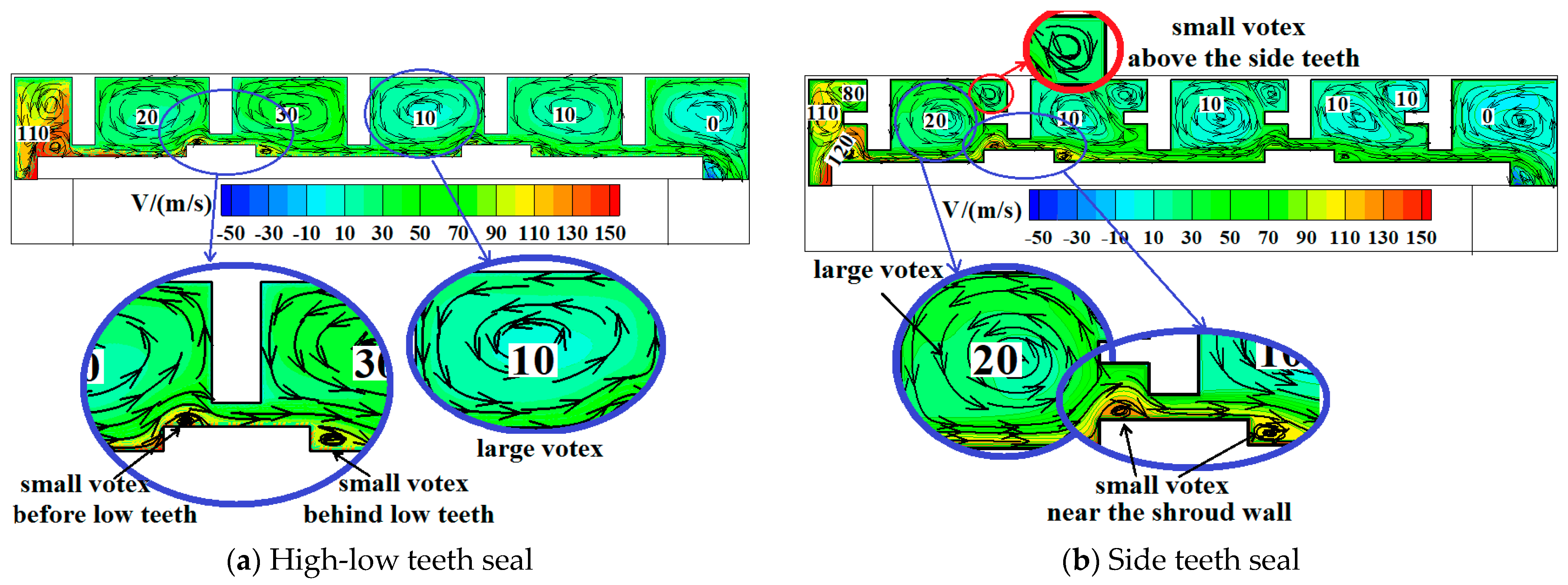
3.1. Flow Field Analysis

Figure 8 depicts the streamlines and circumferential velocity distribution of the flow field within the meridional plane of the blade tip seal clearance. In Figure 8a, two vortices exist within the high-low teeth seal cavity: a large vortex within the cavity and a smaller vortex near the shroud wall. The large vortex results from a reduced steam flow velocity, combined with collisions and friction with the seal teeth and cavity walls, making it a primary form of kinetic energy dissipation within the seal cavity. The smaller vortex near the shroud wall occurs in two forms: one small vortex located before the low teeth, formed as steam accelerates through the seal teeth, imparting energy to a portion of the airflow constrained in front of the teeth; and a second small vortex behind the low teeth, created by a pedestal design that matches the geometry of the step behind it, where a turbulent boundary layer separation generates a clockwise closed recirculation zone. Together, these two small vortices maintain a quasi-stable state under the effect of the jet flow in the seal clearance, ensuring a relatively stable vortex structure. It can be observed that each high-low teeth seal cavity exhibits two oppositely rotating vortex zones: one large and one small. Within the side teeth seal cavity (Figure 8b), the large vortex remains the main form of energy dissipation, while small vortex persists near the shroud wall due to the influence of the pedestal. The distinctive feature is that the side tooth reduces the filling factor of the large vortex while inducing an additional clockwise-rotating minor vortex in the upper region. Consequently, each side-teeth seal cavity develops three characteristic interacting vortices: one large vortex and two small vortices. The interaction among these vortices increases pressure fluctuations within the tip seal, with fluctuations in the shroud wall vortex having a more direct effect on the forces acting on the shroud surface.
Figure 9 illustrates the rotor’s eccentric direction as defined in this study. Figure 10 depicts the pressure variations in the shroud wall vortex for a 0.1 mm eccentricity under both high-low and side teeth seals. The shroud wall vortex pressure fluctuations follow a periodic sinusoidal pattern. Compared to the high-low teeth seal, the side teeth seal exhibits greater shroud wall vortex pressure fluctuation amplitude, suggesting that an increase in vortex structures within the seal cavity amplifies pressure fluctuations. In the direction of rotor eccentricity, the tip clearance narrows, whereas it widens on the opposite side, leading to larger pressure fluctuation amplitudes in wider clearances and smaller amplitudes in narrower clearances. This consistent pattern of pressure fluctuation in both seal types may contribute to the periodic excitation forces observed in the blade tip.
As the shroud wall vortex acts directly on the shroud surface, performing a frequency spectrum analysis on the pressure fluctuations of the shroud wall vortex reveals clearer trends (Figure 11). Each seal cavity’s shroud wall vortex shows a pulsation frequency peak at 5000 Hz, matching the frequency at which a rotor blade passes through a stator blade passage. When a rotor blade enters the stator wake region, the pressure between the rotor and stator increases, leading to a corresponding pressure rise in the tip seal cavity. Conversely, when the rotor blade passage aligns with the stator wake, the pressure between the rotor and stator decreases, causing a reduction in the tip seal cavity pressure. Consequently, the small vortices on the shroud wall exhibit periodic pressure fluctuations synchronized with the rotor rotation. The second and third seal cavities display additional frequency components at twice, thrice, and quadruple the base frequency, though with lower peak values. Furthermore, the pressure fluctuation frequency peaks for wider clearances in the blade tip are consistently higher than those for narrower clearances. Overall, the pulsation pattern of the shroud wall vortex exhibits fundamental synchronization with the rotor blade rotational frequency, while being subject to minor modulation by the internal geometry of the seal cavity.

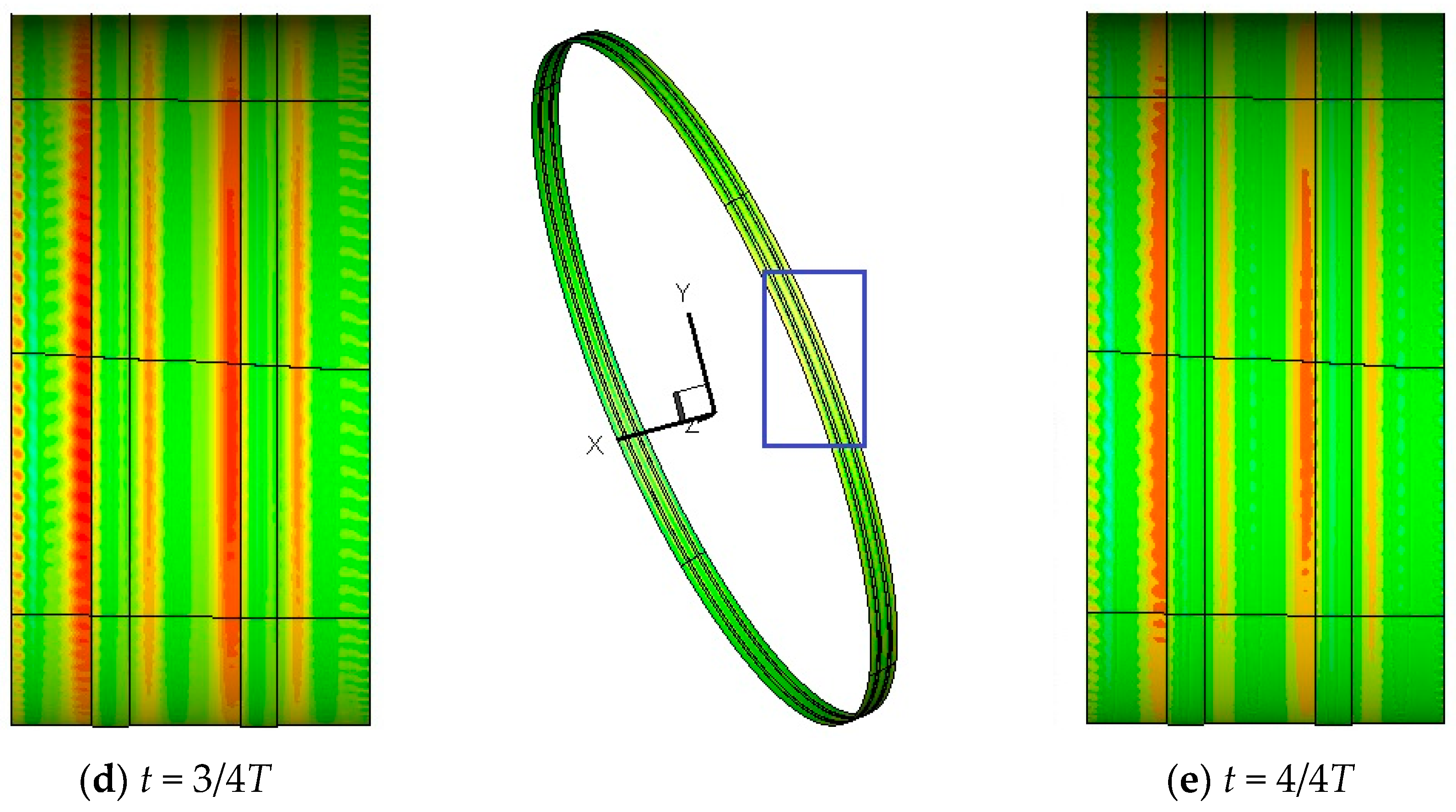
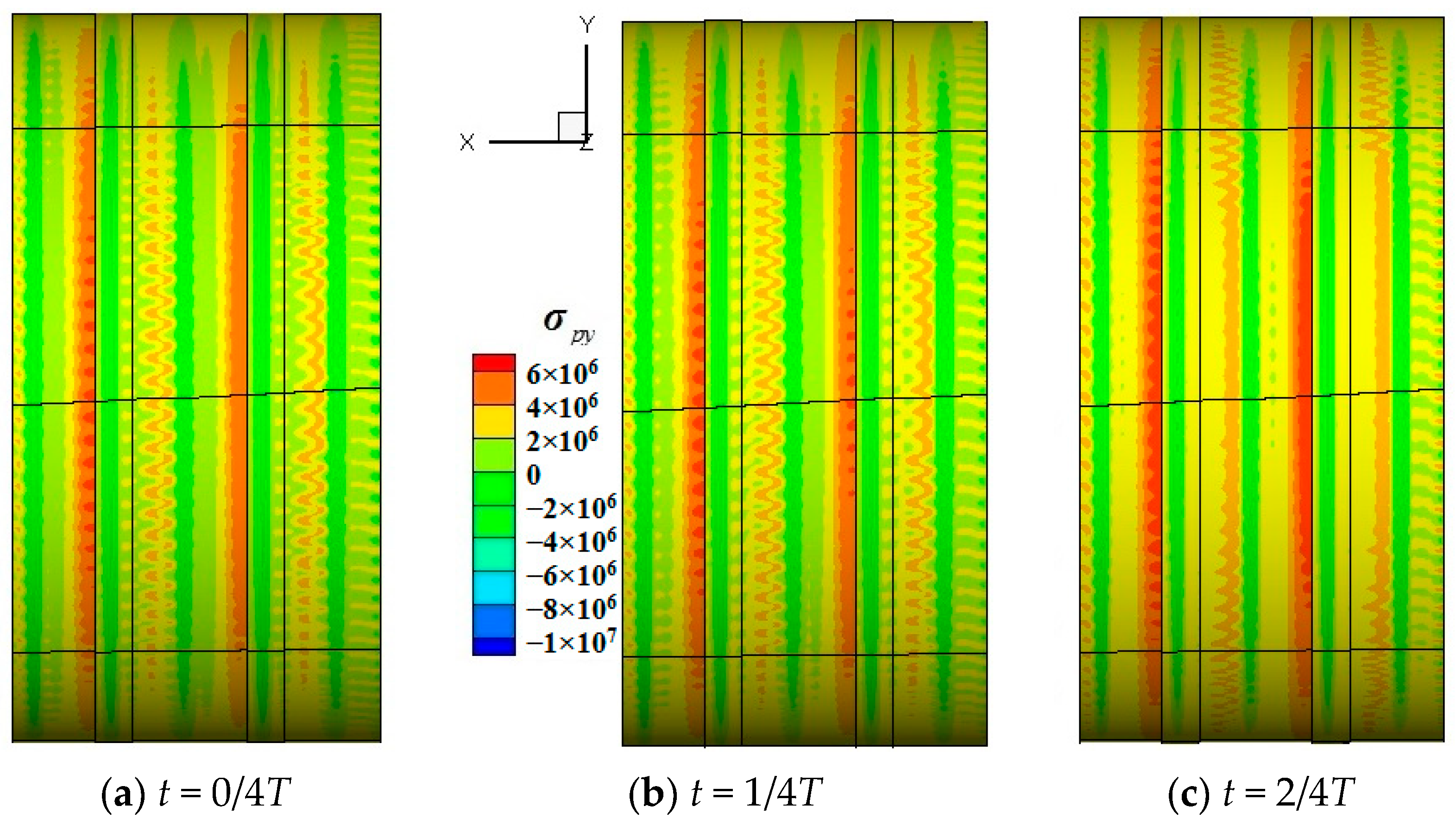
3.2. Analysis of Unsteady Variation in Shroud BVF

An intrinsic relationship exists between the flow field within the blade tip seal and the forces exerted on the shroud surface. To analyze the impact of rotor eccentricity on the shroud surface forces, it is essential to examine BVF. Also referred to as vorticity source strength, BVF represents the vorticity flux per unit area entering the fluid domain through the boundary within a given time interval. The expression for BVF is expressed as follows [30]:
σ = ν n ω
where σ represents BVF; ν represents the kinematic viscosity of the fluid; n represents the unit normal vector of the fluid at the wall surface; and ω represents the vorticity.
Using vector operations, Equation (3) can be rearranged as follows:
σ = n × a n × f + 1 ρ n × p + ν n × × ω
For general three-dimensional viscous (Equation (3)), compressible rotational flows, σ consists of four components. These components are induced by wall fluid acceleration, a, body force, f, shear effect due to the pressure gradient, p , and non-uniform vorticity distribution near the wall, ν × ω . Therefore, Equation (4) can be further expressed as follows:
σ = σ a + σ f + σ p + σ τ
where σ a = n × a represents the component of the fluid acceleration effect and σ f = n × f represents the component of the body force effect. For the blade tip seal clearance region under study, assuming a constant rotor rotational speed and negligible body forces, σ a = σ f = 0 can be considered negligible. In Equation (4), the expression for σ p is given as follows:
σ p = 1 ρ n × p
where ρ represents the density of fluid; n represents the unit normal vector at any point on the wall surface. Let n1, n2, and n3 denote the Cartesian components of vector n along the x, y, and z-axes, respectively. Therefore, the vector form of n can be expressed as:
n = n 1 i + n 2 j + n 3 k
According to Figure 9, when the rotor is set with an eccentricity in the negative z-direction during calculation, the following conditions apply to the shroud surface: the axial component (x-direction) of its unit outer normal vector is zero (n1 = 0). Furthermore, since the rotor is eccentrically displaced in the −z direction, it can be readily derived that:
n 2 = y / r b
n 3 = z + e / r b
where e represents the eccentricity; rb represents the rotor radius.
Using the cross-product, the expression for σ p can be expressed as follows:
σ p = 1 ρ i j k n 1 n 2 n 3 p x p y p z = 1 ρ n 2 p z n 3 p y 1 ρ n 3 p x n 1 p z 1 ρ n 1 p y n 2 p x = 1 ρ y r b p z z + e r b p y 1 ρ z + e r b p x 1 ρ y r b p x
In Equation (4), the expression for σ τ is determined as follows:
σ τ = ν n × × ω
Using the cross-product, the expression for σ τ can be expressed as follows:
σ τ = ν n 2 2 u z x 2 w x 2 + n 3 2 v x 2 2 u y x i + ν n 2 2 u y z 2 w y x + n 3 2 v x y 2 u y 2 j + ν n 2 2 u z 2 2 w x z + n 3 2 v z x 2 u z y k
The expression for σ τ is highly complex, as it originates from either the two-dimensional vorticity of surface shear stress or the two-dimensional divergence of boundary vorticity. The non-uniform distribution of vorticity endows σ τ with a normal component, causing a near-wall vortex line (originally parallel to the object surface) to deflect into the normal direction. This phenomenon is referred to as the ‘vortex lifting mechanism’. However, when the surface curvature is minimal and the Reynolds number is significantly greater than 1, the effect of σ τ can generally be neglected [30].
In analyzing the steam turbine blade tip seal flow field, based on the rotor’s eccentric direction, the variable of interest is σ p y . When σ p y is positive, it indicates that the micro-element of fluid on the wall surface is moving in the positive y-axis direction; conversely, when σ p y is negative, it shows movement in the negative y-axis direction. A positive peak value of σ p y represents the maximum flux of vorticity entering the flow field from the wall along the positive y-axis direction, indicating that the pressure gradient shear effect on the fluid results in the strongest force exerted on the solid.
Figure 12 illustrates the distribution of BVF along the shroud surface near the minimum circumferential clearance at various representative times within one rotational cycle of the high-low teeth seal. This minimum clearance position was selected for display as it exhibits the positive peak of σ p y when the rotor is eccentric. The position distribution of the positive peak is relatively stable, but σ p y exhibits a strong–weak–strong periodic variation within one rotational cycle. At times 0/4T and 4/4T, the value of σ p y in the shroud vortex region is minimal, while at 2/4T, σ p y reaches its maximum value, with the influence of the circumferential spiral vortex being most significant. The periodic changes in BVF lead to fluctuations in shroud shear stress, subsequently affecting lateral steam excitation force at the blade tip.
Figure 13 depicts the distribution of the BVF on the shroud surface near the minimum circumferential clearance at various representative times within one rotational cycle of the side teeth seal. In this study, changes in the position and distribution of the positive peak of BVF are observed at each representative moment. At 0/4T, the BVF in the shroud vortex region behind the pedestal exhibits a wavelike distribution. By 1/4T, the wavelike BVF in the vortex region behind the pedestal starts expanding at the minimum circumferential clearance of the blade tip, with the peak shifting closer to the seal exit. At 2/4T, the BVF in the shroud vortex region behind the pedestal forms an elongated distribution near the minimum circumferential clearance of the blade tip, with the peak σ p y shifting to the right side of this cavity. By 3/4T, the peak σ p y in the shroud vortex region near the minimum circumferential clearance begins moving back into the cavity, returning to a wavelike distribution pattern, and by 4/4T, it reverts to the distribution observed at 0/4T. This periodic variation in BVF distribution corresponds to the fluctuation of the shroud wall vortex behind the pedestal. Compared to the high-low teeth seal, the side teeth seal exhibits greater variations in BVF over one rotational cycle near the minimum circumferential clearance at the blade tip. This suggests that the side teeth seal will experience larger amplitude fluctuations in shroud shear stress.
Figure 14 illustrates the variation in peak BVF over time on the shroud surface for two types of seals. The peak BVF in the front vortex regions of the low teeth in both seal types exhibit a periodic fluctuation pattern. The period of this fluctuation corresponds to the time it takes for a rotor blade to pass through a stator blade passage. In contrast, the rear vortex regions of the low teeth show less consistent periodicity in BVF fluctuations due to the effect of vortex shedding. For the high-low teeth seal, the peak BVF in the front vortex regions of the low teeth is consistently higher than that in the rear vortex regions, although the amplitude of their fluctuations is similar. Meanwhile, for the side teeth seal, the fluctuation amplitude of BVF in the front vortex regions of the low teeth is more pronounced. The main difference in peak BVF between the two teeth seal types lies in the front vortex regions of the low teeth; the side teeth seal shows more significant fluctuations over time. The periodic changes in BVF on the shroud surface are a primary factor inducing fluctuations in the lateral steam excitation force at the blade tip. This fluctuating excitation force, affected by the periodic behavior of BVF, can affect the stability and safety of the turbine unit.

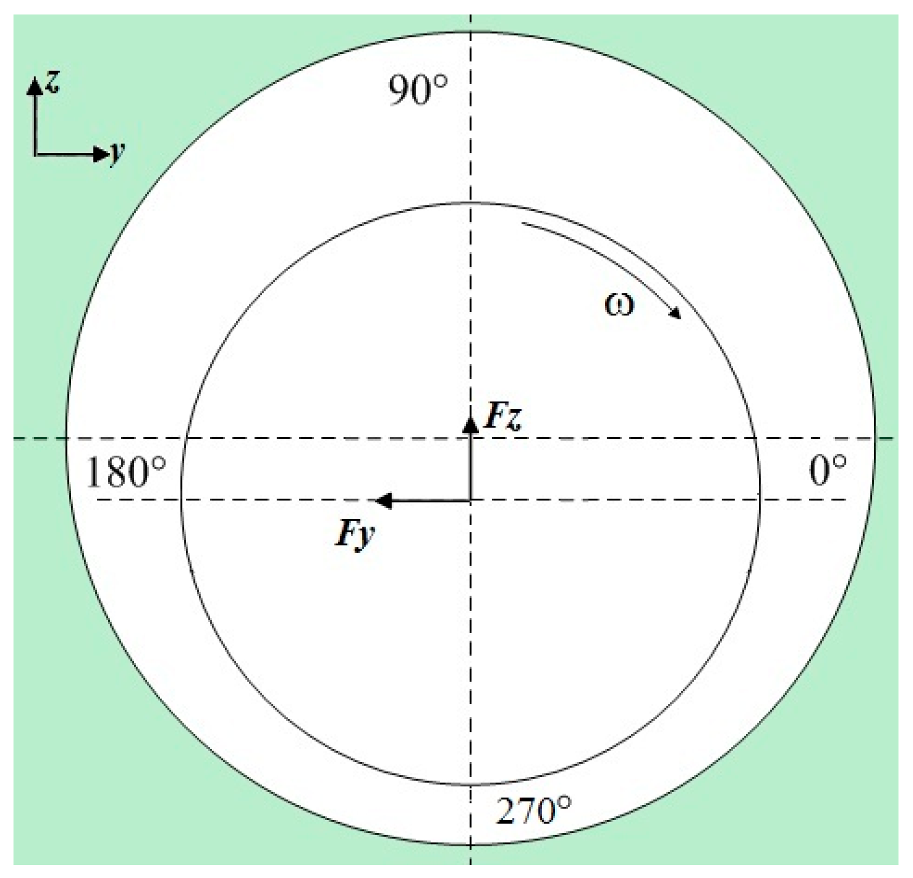
3.3. Analysis of Blade Tip Seal Steam Flow Excitation Force Fluctuation Patterns

Figure 15 depicts the temporal fluctuation pattern of the lateral steam flow excitation force at the blade tip when the rotor eccentricity is 0.1 mm. As previously discussed, the fluctuations in the lateral steam-induced excitation force at the blade tip are attributed to the periodic variations in BVF along the shroud surface. For both high-low teeth and side teeth seals, the peak BVF occurs in the shroud wall vortex region. The periodic vortex motion in this region inevitably leads to systematic changes in the distribution of BVF on the shroud surface, consequently causing fluctuations in the lateral steam-induced excitation force at the blade tip. When comparing the two seal types, the fluctuation amplitude of the lateral excitation force in the high-low teeth seal stabilizes at approximately 6 N, while in the side teeth seal, it stabilizes at approximately 17 N. This fluctuation pattern aligns with the periodic variation in BVF observed earlier. The larger fluctuation amplitude of BVF in the side teeth seal leads to a lateral excitation force fluctuation amplitude approximately three times that of the high-low teeth seal. The frequency spectrum of the lateral steam-induced excitation force reveals that both seal types exhibit a similar peak frequency at approximately 5000 Hz. This indicates a consistent fluctuation pattern between the blade tip flow excitation force and the blade tip leakage vortex dynamics. The larger fluctuation amplitude in the lateral excitation force for the side teeth seal suggests that the more complex vortex motion within the blade tip seal flow field generates substantial fluctuations in the excitation force, which can negatively affect rotor stability.
Throughout each moment within a rotational cycle, the unsteady effects cause pressure fluctuations in the circumferential large and small clearances in the eccentric seal flow field, leading to changes in the radial steam-induced excitation force across the shroud surface at the blade tip clearance. Figure 16 illustrates the temporal variation in the radial steam-induced excitation force at the blade tip under 0.1 mm eccentricity condition. Both seal types exhibit similar trends, demonstrating a consistent sinusoidal pattern with a 0.2 ms periodicity in the fluctuations. Furthermore, the amplitude of radial steam-induced excitation force fluctuations induced by the pressure pulsations of the leakage vortex within the seal clearance is relatively low. Under the conditions studied, the fluctuation amplitude of the radial steam-induced excitation force is approximately 7 N for the high-low teeth seal and 12 N for the side teeth seal. Both seal types also exhibit a similar peak frequency of 5000 Hz for the radial steam-induced excitation force, confirming that the radial steam-induced excitation force displays a periodic fluctuation pattern aligned with the pressure pulsation within the blade tip seal cavity.

4. Conclusions

In this paper, a full-cycle three-dimensional model of a steam turbine high-pressure stage is established. The non-uniform flow field distribution within the tip seal and the variation characteristics of steam excitation forces under rotor eccentric conditions are calculated using CFD/FLUENT. The relationship between leakage vortex evolution and steam excitation forces in the non-uniform tip flow field was thoroughly analyzed through the introduction of a boundary vorticity flux (BVF) into the tip seal cavity flow field. The specific conclusions are as follows:
(1)
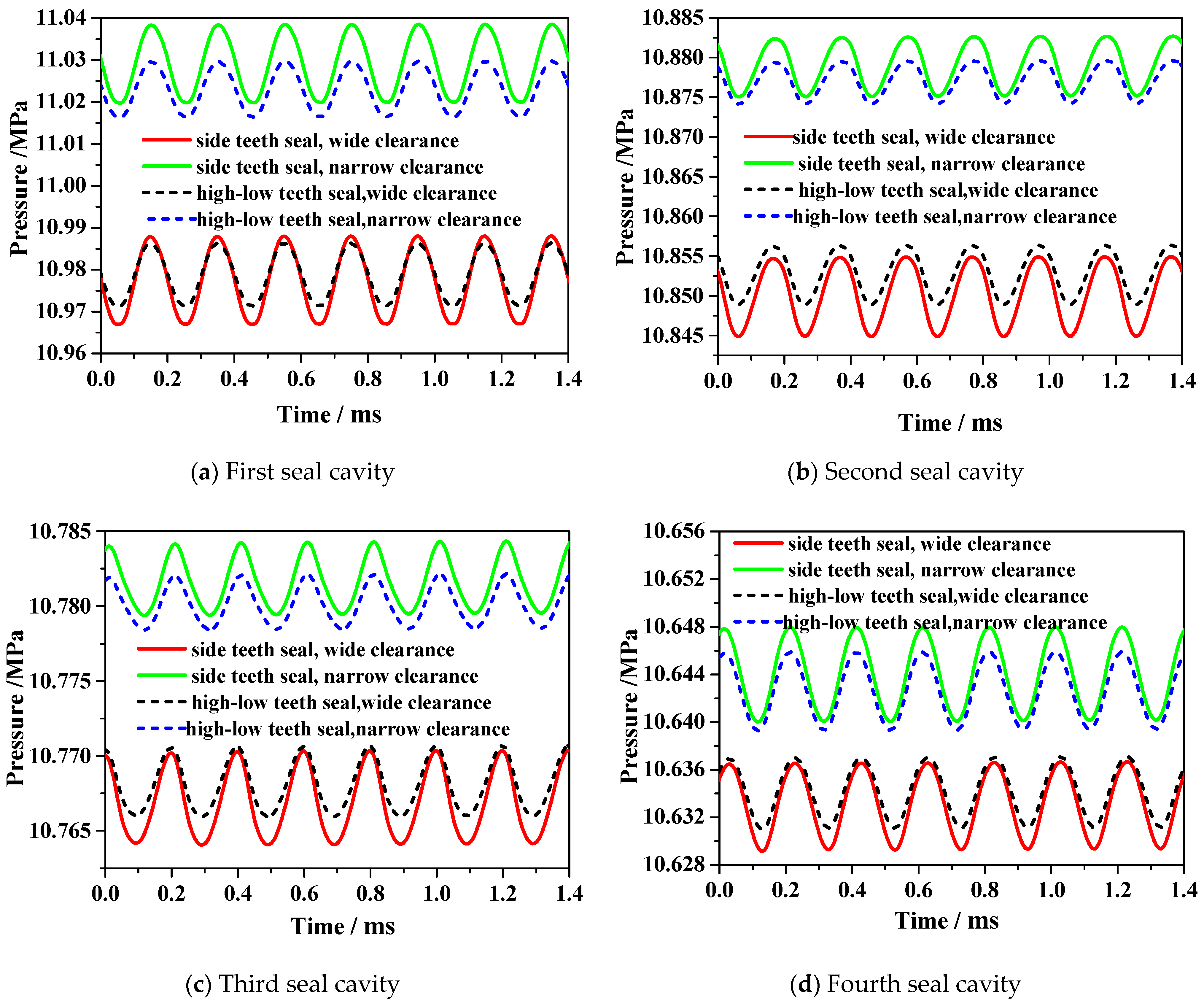
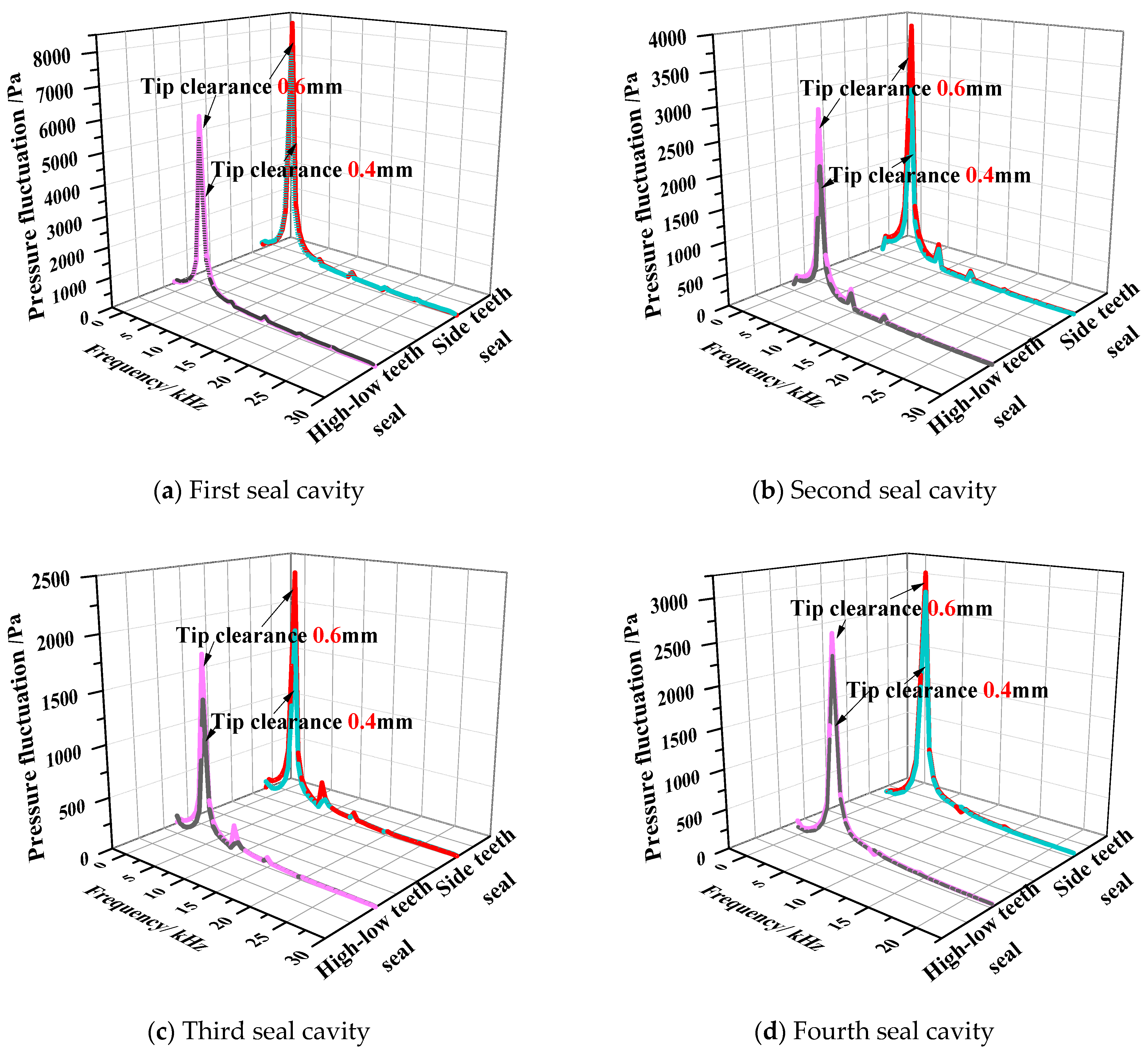
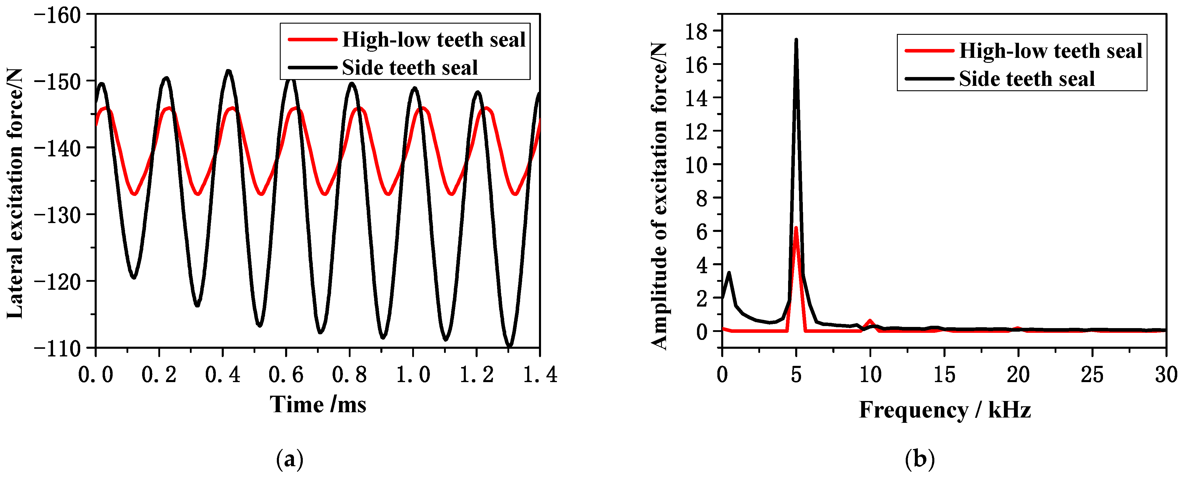
The vortex system within the seal primarily consists of large vortices in the cavity and smaller vortices near the shroud wall. The shroud wall vortices exhibit periodic sinusoidal fluctuations, with a period corresponding to the time it takes for a rotor blade to pass through a stator blade passage. Compared to high-low teeth seals, side teeth seals exhibit a greater amplitude of shroud wall vortex pressure fluctuations, indicating that an increase in vortex structures within the seal cavity intensifies pressure fluctuations.
(2)
By introducing BVF, a relationship is established between the flow field in the blade tip seal clearance and the forces on the shroud surface. The effect of the leakage flow field on the lateral excitation force in the blade tip seal can be characterized by the distribution of BVF along the shroud surface. The periodic changes in BVF align with the fluctuation patterns of both the shroud wall vortices within the seal flow field and the lateral excitation force.
(3)
The instability of the leakage flow in the blade tip clearance induces fluctuations in the steam excitation force. The vortex motion in the shroud wall leads to periodic changes in BVF on the shroud surface, which are the primary cause of fluctuations in the lateral excitation force within the blade tip seal. Additionally, the unsteady circumferential pressure differential within the blade tip seal clearance ultimately results in fluctuations in the radial excitation force.
(4)
An increase in vortices within the tip seal cavity intensifies vortex–vortex interactions, leading to greater pressure fluctuation amplitudes and consequently larger induced steam excitation force variations. This phenomenon adversely affects rotor operational stability. By elucidating the mechanism of vortex-induced steam excitation force fluctuations in the tip seal cavity, this study provides theoretical foundations and references for enhancing steam turbine operational safety.

Author Contributions

Conceptualization, P.L. and H.W.; Data curation, P.L.; Formal analysis, H.W.; Funding acquisition, H.S.; Methodology, P.L.; Project administration, H.P.; Resources, H.S.; Software, T.J.; Supervision, T.J.; Validation, H.P.; Visualization, H.S.; Writing—original draft, P.L.; Writing—review and editing, P.L. All authors have read and agreed to the published version of the manuscript.

Funding

This research was funded by National Natural Science Foundation of China, grant number 52206004.

Data Availability Statement

The original contributions presented in the study are included in the article, further inquiries can be directed to the corresponding author.

Acknowledgments

The authors thank the editors and reviewers for their comments and help.

Conflicts of Interest

Author Haichao Peng was employed by the company State Grid Songyuan Elect Power Supply Co. The remaining authors declare that the research was conducted in the absence of any commercial or financial relationships that could be construed as a potential conflict of interest.

Nomenclature

The following symbols and abbreviations are used in this manuscript:
Roman letters
pPressure [Pa]
TTemperature [K]
y+Dimensionless wall distance [-]
kTurbulent kinetic energy [m2s−2]
eEccentricity [m]
rbRotor radius [m]
n(n1, n2, n3)Unit normal vector and its components in the Cartesian coordinate system
V(u, v, w)Velocity vector and its components in the Cartesian coordinate system [m s−1]
aAcceleration [m s−2]
fBody force [N m−3]
Greek letters
ωVorticity [s−1]
ωSpecific dissipation rate [m2s−3]
ηIsentropic efficiency [-]
γAdiabatic index [-]
τShear stress [-]
ρDensity [kg m−3]
νKinematic viscosity [m2s−1]
σ Boundary Vorticity Flux [-]
σ p y Radial BVF [-]
Abbreviations
CFDComputational fluid dynamics
BVFBoundary Vorticity Flux
LESLarge Eddy Simulation
SSTShear Stress Transport

References

  1. Gao, J.; Zheng, Q.; Zhang, H.; Chen, H. Comparative investigation of tip leakage flow and its effect on stage performance in shrouded and unshrouded turbines. J. Aerosp. Power 2016, 227, 1265–1276. [Google Scholar] [CrossRef]
  2. Zhang, J.; Liu, M.; Peng, N. Study of heat transfer and leakage characteristics of brush seals based on local temperature non-equilibrium model. Machines 2022, 10, 823. [Google Scholar] [CrossRef]
  3. Biassoni, D.; Barsi, D.; Lengani, D. Effect of purge on secondary flows in turbine due to interaction between cavity flow and main channel. Machines 2025, 13, 77. [Google Scholar] [CrossRef]
  4. Molale, T.; Ahmed, N.; Bhamjee, M. Numerical analysis of flow induced vibrations of a low-pressure steam turbine rotating blade. JPCS 2019, 1378, 32–43. [Google Scholar] [CrossRef]
  5. Cao, L.H.; Wang, J.X.; Li, P.; Yun, A.X. Analysis on structure and high loss zone of tip leakage flow in steam turbine. Proc. CSEE 2018, 38, 2055–2062+2220. [Google Scholar]
  6. Sun, D.; Xiao, Z.H.; Zheng, T.S.; Wang, X.J. Study on influence factors of tangential fluid-induced force and radial fluid-induced force in seals. Lubr. Eng. 2013, 9, 33–36. [Google Scholar]
  7. Xue, C.; Cao, L.H.; Si, H.Y. Anisotropic Vibration Characteristics Analysis of Steam Turbine Rotor Influenced by Steam Flow Excited Force Coupling Thermal and Dynamic Loads. J. Energy Resour. Technol. 2023, 145, 071703. [Google Scholar] [CrossRef]
  8. Sun, T.; Liu, Y.Z.; Ma, Z.L. Numerical simulation of the relationship between steam flow excitation characteristics and coverage on the governing stage of marine steam turbine. Ocean. Eng. 2024, 314, 119526. [Google Scholar] [CrossRef]
  9. Chen, Y.X.; Li, Z.G.; Li, J. Fluid excited rotor dynamic characteristics of labyrinth seal during non-uniform inlet flowing. J. Xi’an Jiaotong Univ. 2017, 51, 145–152. [Google Scholar]
  10. Si, H.Y.; Cao, L.H.; Li, P. Effect of seal structure on rotor dynamic characteristics of steam turbine. Proc. CSEE 2020, 40, 165–175+384. [Google Scholar]
  11. Wang, H.; Wu, Y.D.; Ouyang, H.; Du, Z.H. Circumferential propagating characteristics of tip leakage flow oscillation and its induced rotating pressure wave. Proc. Inst. Mech. Eng. Part A J. Power Energy 2016, 230, 374–387. [Google Scholar]
  12. Towne, A.; Schmidt, O.T.; Colonius, T. Spectral proper orthogonal decomposition and its relationship to dynamic mode decomposition and resolvent analysis. J. Fluid Mech. 2018, 847, 821–867. [Google Scholar] [CrossRef]
  13. Jeffrey, M.J. Three-dimensional CFD rotordynamic analysis of gas labyrinth seals. J. Vib. Acoust. 2003, 125, 427–433. [Google Scholar]
  14. Zou, D.L.; Xue, L.; Yang, Y.Z.; Dong, X.G.; Ta, N.; Rao, Z.S. Research on the excitation force and vortex dynamics characteristics of pump-jet propulsor induced by shafting whirling vibration: Non-uniform blade tip clearance. Phys. Fluids 2024, 36, 065104. [Google Scholar] [CrossRef]
  15. Gu, Q.L.; Yang, J.G.; Zhang, W.F.; Zhang, M.J. On the rotordynamic performance of an annular gas seal with self-adaptive jet slots: Comparisons to the swirl brake and shunt injection. Tribol. Int. 2022, 176, 107898. [Google Scholar] [CrossRef]
  16. Zhang, Y.; Zhang, W.F.; Gu, Q.L. Research on suppression method for circumferential flow and fluid-induced vibration of blade tip seal. J. Vib. Shock 2020, 39, 228–233. [Google Scholar]
  17. Sun, D.; Su, G.Z.; Zhao, H. Dynamic characteristics of labyrinth seal and rotor stability considering swirl brakes. J. Aerospace. Eng. 2023, 36, 04023057. [Google Scholar] [CrossRef]
  18. Lang, J.; Yang, J.G.; Cao, H. Calculation and experimental comparison of fluid induced force between the titling pad seal and the fixed pad seal. J. Mech. Eng. 2013, 49, 101–105. [Google Scholar] [CrossRef]
  19. Rzadkowski, R.; Rokicki, E.; Piechowski, L.; Szczepanik, R. Analysis of middle bearing failure in rotor jet engine using tip-timing and tip-clearance techniques. Mech. Syst. Signal. Pract. 2014, 76, 213–227. [Google Scholar] [CrossRef]
  20. Liu, B.; Hou, W.M.; Ma, C.Y.; Wang, Y.G. Measurement and analysis of tip clearance unsteady flow spectrum in axial-flow fan rotor. Front. Energy 2008, 2, 448–452. [Google Scholar] [CrossRef]
  21. Donghyun, Y.; Meng, W.; Parviz, M.; Rajat, M. Vortex dynamics and low-pressure fluctuations in the tip-clearance flow. J. Fluids Eng. 2007, 129, 1002–1014. [Google Scholar]
  22. Li, P.; Cao, L.H.; Si, H.Y. Investigation on the unsteady pressure fluctuation characteristic in the blade tip seal of steam turbine based on spectrum. Therm. Sci. 2020, 24, 3823–3834. [Google Scholar] [CrossRef]
  23. Wang, H.; Wu, Y.D.; Ouyang, H. Aerodynamic rotating instability and fluctuated characteristics of tip clearance flow in low speed axial flow compressor. J. Aerosp. Power 2016, 31, 2239–2250. [Google Scholar]
  24. Wu, J.Z.; Wu, J.M. Interaction between a solid surface and a viscous compressible flow field. J. Fluid Mech. 1993, 254, 183–211. [Google Scholar] [CrossRef]
  25. Ahmed, N.A.; Yen, J. Synthetic Jets as a Boundary Vorticity Flux Control Tool. AIAA J. 2013, 51, 510–513. [Google Scholar]
  26. Liu, H.; Jiang, B.Y.; Wang, W.; Yang, X.P.; Wang, J. Redesign of Axial Fan Using Viscous Inverse Design Method Based on Boundary Vorticity Flux Diagnosis. J. Turbomach. 2021, 143, 051006. [Google Scholar] [CrossRef]
  27. Zeng, Y.; Wang, H.B.; Xiong, D.P.; Yang, Y.X.; Sun, M.B.; Liu, W.D. A multi-physics correction of the shear-stress transport turbulence model for supersonic flows. Phys. Fluids 2024, 36, 125–139. [Google Scholar] [CrossRef]
  28. Cravero, C.; Marelli, S.; Marsano, D.; Usai, V. Fluid dynamic analysis and design strategies for a deswirler device for the direct measurement of radial turbine isentropic efficiency in experimental test rig. J. Heat Fluid Flow 2024, 106, 109270. [Google Scholar] [CrossRef]
  29. Li, P.; Cao, L.H. Effect of rotor-stator axial gap on the tip seal leakage flow of a steam turbine. J. Therm. Sci. 2021, 30, 973–982. [Google Scholar] [CrossRef]
  30. Tong, B.G.; Yin, X.Y.; Zhu, K.Q. The Theory of Vortex Motion, 3rd ed.; University of Science and Technology of China Press: Beijing, China, 2019; pp. 66–73. [Google Scholar]
Figure 1. Overall flow chart.
Machines 13 00518 g001
Figure 2. Calculation model.
Machines 13 00518 g002
Figure 3. Physical models and grids.
Machines 13 00518 g003
Figure 4. Grid independence verification.
Machines 13 00518 g004
Figure 5. Overall structure of the test bench.
Machines 13 00518 g005
Figure 6. Diagram of measurement points of tip seal cavities [29].
Machines 13 00518 g006
Figure 7. Comparison of unsteady numerical calculation and experimental results.
Machines 13 00518 g007
Figure 8. Circumferential velocity and streamlines in tip seal clearance.
Machines 13 00518 g008
Figure 9. Rotor eccentricity of steam turbine.
Machines 13 00518 g009
Figure 10. Temporal variation in pressure at the vortex core in the shroud wall vortex of the blade tip seal.
Machines 13 00518 g010
Figure 11. Frequency spectrum of pressure pulsation of the shroud wall vortexes.
Machines 13 00518 g011
Figure 12. Distribution of BVF on the shroud under eccentricity in high-low-teeth seal.
Machines 13 00518 g012aMachines 13 00518 g012b
Figure 13. Distribution of BVF on the shroud under eccentricity in side-teeth seal.
Machines 13 00518 g013aMachines 13 00518 g013b
Figure 14. Temporal variation in the peak BVF on the shroud surface.
Machines 13 00518 g014
Figure 15. Variation in lateral steam-induced excitation force of the tip seal with time. (a) Steam-induced excitation force. (b) Spectrum analysis.
Machines 13 00518 g015
Figure 16. Variation in radial steam-induced excitation force of the tip seal with time. (a) Steam-induced excitation force. (b) Spectrum analysis.
Machines 13 00518 g016
Table 1. Parameters of blade in second stage of steam turbine.
Parameter/NameUnitValue
Hub radiusmm413.3
Blade heightmm72.1
Blade chord lengthmm33.03
Number of blades 98
Blade installation angle°50.54
Rotational speedr/min3000
Seal high tooth length/amm4
Seal low tooth length/bmm3
Pedestal length/cmm3
Pedestal height/hmm1
Side tooth length/dmm1
Total length of blade tip seal/tmm38.2
Radial clearance of blade tip seal/ δ r mm0.5
Axial gap of tip seal/ δ z mm2
Disclaimer/Publisher’s Note: The statements, opinions and data contained in all publications are solely those of the individual author(s) and contributor(s) and not of MDPI and/or the editor(s). MDPI and/or the editor(s) disclaim responsibility for any injury to people or property resulting from any ideas, methods, instructions or products referred to in the content.

