
Analysis of the Influence of Drill Tip Geometry on the Dry Drilling Process in CFRP Thermoset Laminate


Abstract
1. Introduction
2. Experimental Procedures
2.1. Material
2.2. Drilling Process and Tool
3. Results
3.1. Delamination Factor
3.2. Defects on the Hole Exit Surface
3.3. Average Roughness
4. Discussion
5. Conclusions
- -
- The delamination defect was characterized as a spalling defect, being more severe at the hole exit than at the hole entrance, due to the lower resistance of the laminate in the final drilling stage, at the four feed rates evaluated for the 118° and 140° drills.
- -
- The drill with an angle of 118° showed superior performance compared to the 140º drill at feed rates of 0.060 mm/rev and 0.090 mm/rev, evidencing the influence of the tool angle on the generation of delamination-type damage. Furthermore, this tool obtained Fda values close to those of the 60° and 130° drill at feed rates of 0.090 mm/rev. This suggests that the use of conventional drills may be viable in the machining of CFRP laminates, enabling a reduction in operating costs without significantly compromising the quality of the finish, especially with regard to delamination.
- -
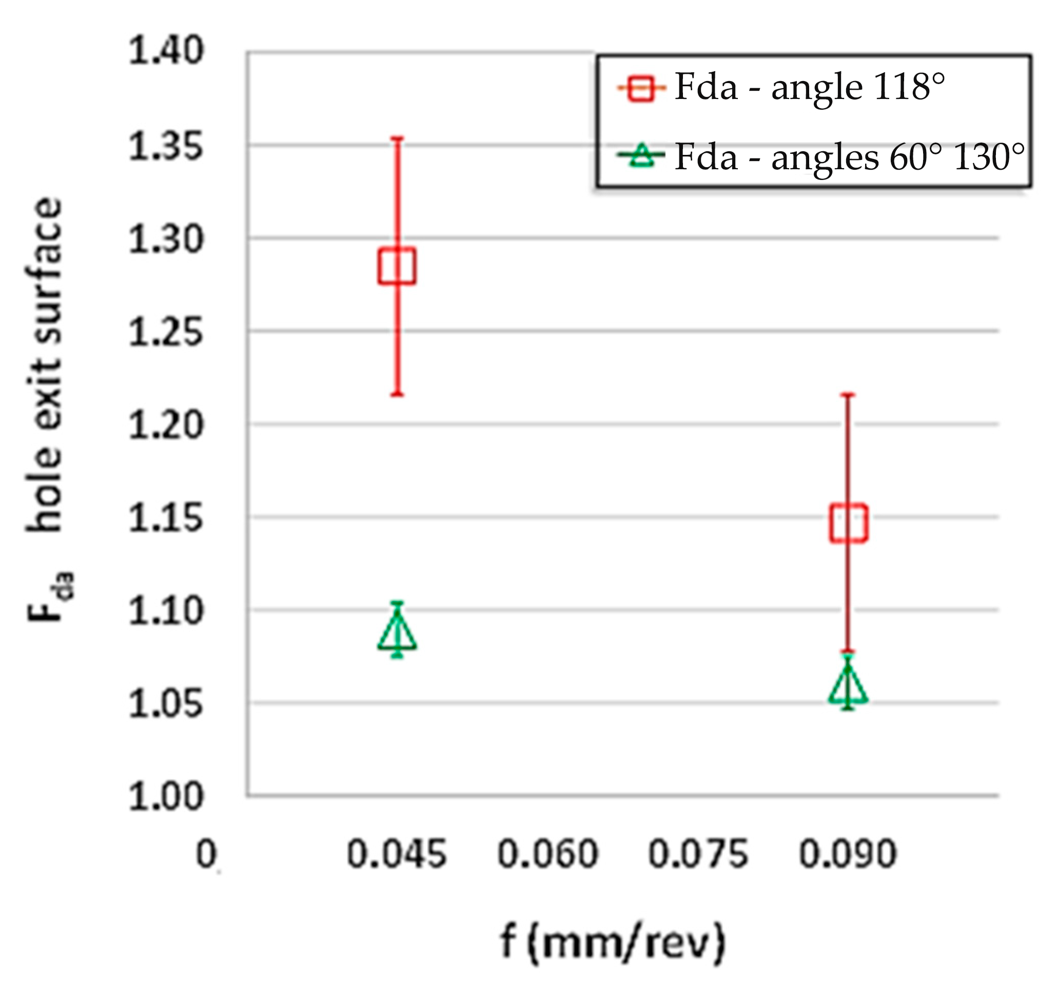
- The defect analysis revealed a higher incidence of burrs and uncut fibres at the hole exit compared to the entry, especially when drilling with the 118° and 140° drills, at all feed rates considered. This result indicates that the feed rate of 0.090 mm/rev, associated with a constant cutting speed of 60 m/min and the use of the 118° drill, constitutes the most favourable processing condition for minimizing the generation of defects. The comparison of the Fda values obtained with the 118º drills in relation to the specific drill for composites of 60° and 130°, revealed that, although the conventional tools present higher Fda values, both follow a trend of improvement with increasing feed.
- -
- The evaluation of the surface finish, through the average roughness (Ra), indicated that the drill with an angle of 140° provided better results compared to the one with 118° and, when compared at feed rates of 0.045 mm/rev and 0.090 mm/rev with the results of the drill with an angle of 60° and 130°, they were close. These results can be credited to the relationship between the angle of the drill tip and the nature of the thermosetting matrix due to its high melting point and the thickness of the laminate in drilling under dry conditions.
Author Contributions
Funding
Data Availability Statement
Acknowledgments
Conflicts of Interest
References
- Toti, F.A. Drilling behavior of thermoplastic and thermoset CFRP laminates under cryogenic cooling and dry machining. In Proceedings of the 7th Brazilian Conference on Composite Materials, Brasília, Brazil, 14–17 July 2024; pp. 301–3011. [Google Scholar]
- Xu, J.; Yin, Y.; Davim, J.P.; Li, L.; Ji, M.; Geier, N.; Chen, M. A critical review addressing drilling-induced damage of CFRP composites. Compos. Struct. 2022, 294, 115594. [Google Scholar] [CrossRef]
- Romoli, L.; Lutey, A.H.A. Quality monitoring and control for drilling of CFRP laminates. J. Manuf. Process. 2019, 40, 16–26. [Google Scholar] [CrossRef]
- Gupta, A.; Ascroft, H.; Barnes, S. Effect of chisel edge in ultrasonic assisted drilling of carbon fibre reinforced plastics (CFRP). In Proceedings of the 7th HPC 2016, Chemnitz, Germany, 31 May–2 June 2016. [Google Scholar]
- Rathod, D.; Rathod, M.; Patel, R.; Shahabaz, S.M.; Shetty, S.D.; Shetty, N. A review on strengthening, delamination formation and suppression techniques during drilling of CFRP composites. Cogent Eng. 2021, 8, 1941588. [Google Scholar] [CrossRef]
- Kudus, M.H.A.; Ratnam, M.M.; Akil, H.M. Factors affecting hole quality during drilling of natural fibre-reinforced composites: A comprehensive review. J. Reinf. Plast. Compos. 2021, 40, 391–405. [Google Scholar] [CrossRef]
- Bhattacharyya, D.; Horrigan, D.P.W. A study of hole drilling in Kevlar composites. Compos. Sci. Technol. 1998, 58, 267–283. [Google Scholar] [CrossRef]
- Khashaba, U.A. Drilling of polymer matrix composites: A review. J. Compos. Mater. 2012, 47, 1817–1832. [Google Scholar] [CrossRef]
- Hocheng, H.; Tsao, C.C. Effects of special drill bits on drilling-induced delamination of composite materials. Int. J. Mach. Tools Manuf. 2006, 46, 1403–1416. [Google Scholar] [CrossRef]
- Girot, F.G.; Dau, F.; Gutiérrez-Orrantia, M.E. New analytical model for delamination of CFRP during drilling. J. Mater. Process. Technol. 2017, 240, 332–343. [Google Scholar] [CrossRef]
- Durão, L.M.P.; Gonçalves, D.J.; Tavares, J.M.R.; de Albuquerque, V.H.C.; Vieira, A.A.; Marques, A.T. Drilling tool geometry evaluation for reinforced composite laminates. Compos. Struct. 2010, 92, 1545–1550. [Google Scholar] [CrossRef]
- Bonnet, C.; Poulachon, G.; Rech, J.; Girard, Y.; Costes, J.P. CFRP drilling: Fundamental study of local feed force and consequences on hole exit damage. Int. J. Mach. Tools Manuf. 2015, 94, 57–64. [Google Scholar] [CrossRef]
- Mohd, A.M.; Ahmad, F.; Shariff, S.; Woo, T.K. Effects of Twist Drill Point Angle on Thrust Force and Delamination Factor in Hybrid Fibre Composites Drilling. Appl. Mech. Mater. 2014, 564, 501–506. [Google Scholar]
- Sereshk, M.R.V.; Bidhendi, H.M. The Contribution of different fracture modes on drilling delamination crack propagation. J. Manuf. Sci. Eng. 2017, 139, 011013. [Google Scholar] [CrossRef]
- Al-wandi, S.; Ding, S.; Mo, J. An Approach to evaluate delamination factor when drilling carbon fiber-reinforced plastics using different drill geometries: Experiment and finite element study. Int. J. Mach. Tools Manuf. 2017, 93, 4043–4061. [Google Scholar] [CrossRef]
- Faraz, A.; Biermann, D.; Weinert, K. Cutting edge rounding: An innovative tool wear criterion in drilling CFRP composite laminates. Int. J. Mach. Tools Manuf. 2009, 49, 1185–1196. [Google Scholar] [CrossRef]
- Xu, J.; Lin, T.; Davim, J.P.; Chen, M.; El Mansori, M. Wear behavior of special tools in the drilling of CFRP composite laminates. Wear 2021, 476, 203738. [Google Scholar] [CrossRef]
- Hassan, M.H.; Abdullah, J.; Franz, G. Multi-Objective Optimization in Single-Shot Drilling of CFRP/Al Stacks Using Customized Twist Drill. Materials 2022, 15, 1981. [Google Scholar] [CrossRef]
- Bolat, Ç.; Karakılınç, U.; Yalçın, B.; Öz, Y.; Yavaş, Ç.; Ergene, B.; Ercetin, A.; Akkoyun, F. Effect of Drilling Parameters and Tool Geometry on the Thrust Force and Surface Roughness of Aerospace Grade Laminate Composites. Micromachines 2023, 14, 1427. [Google Scholar] [CrossRef]
- Xu, J.; Geier, N.; Shen, J.; Krishnaraj, V.; Samsudeensadham, S. A review on CFRP drilling: Fundamental mechanisms, damage issues, and approaches toward high-quality drilling. J. Mater. Res. Technol. 2023, 24, 9677–9707. [Google Scholar] [CrossRef]
- Xu, C.; Liu, X.; Li, F.; Fu, H.; Han, D.; Huang, N.; Wang, G.; Wang, Y. Wear mechanism analysis of internal chip removal drill for CFRP drilling. Sci. Eng. Compos. Mater. 2024, 31, 20240013. [Google Scholar] [CrossRef]
- Chen, W.-C. Some Experimental Investigations in the Drilling of Carbon Fibre Reinforced Plastic (CFRP) Composite Laminates. Int. J. Mach. Tools Manuf. 1997, 37, 1097–1108. [Google Scholar] [CrossRef]
- Joshi, S.; Rawat, K. A novel approach to predict the delamination factor for dry and cryogenic drilling of CFRP. J. Mater. Process. Technol. 2018, 262, 521–531. [Google Scholar] [CrossRef]
- Davim, J.P.; Rubio, J.C.; Abrao, A.M. A Novel approach based on digital image analysis to evaluate the delamination factor after drilling composite laminates. Compos. Sci. Technol. 2007, 67, 1939–1945. [Google Scholar] [CrossRef]
- Toti, F.A. Comparative Study of the Behavior in Dry and Cooled Drilling Machining of Aeronautical Grade Thermoplastic and Thermoset Composite Laminates. Ph.D. Thesis, São Carlos Campus, The University of São Paulo, São Paulo, Brazil, 2023. [Google Scholar]
- HEXCEL. Hexply® 8552—Product Data Sheet—EU Version. [s. 1.]; 2016; pp. 1–6. Available online: https://www.hexcel.com/user_area/content_media/raw/HexPly_8552_eu_DataSheet(1).pdf (accessed on 10 March 2023).
- DIN 6537:2020-10; Solid-Hardmetall Twist Drills with Stepped Parallel Shank- Dimensions. Deutsches Institut Fur Normung E.V. (German National Standard): Berlin, Germany, 2020.
- DIN 8037; Twist Drills with Parallel Shank with Carbide Tips for Drilling Metal. Deutsches Institut Fur Normung E.V. (German National Standard): Berlin, Germany, 1971.
- Batista, M.F.; Basso, I.; de Assis Toti, F.; Rodrigues, A.R.; Tarpani, J.R. Cryogenic drilling of carbon fibre reinforced thermoplastic and thermoset polymers. Compos. Struct. 2020, 251, 112625. [Google Scholar] [CrossRef]
- Geng, D.; Liu, Y.; Shao, Z.; Lu, Z.; Cai, J.; Li, X.; Jiang, X.; Zhang, D. Delamination formation, evaluation and suppression during drilling of composite laminates: A review. Compos. Struct. 2019, 216, 168–186. [Google Scholar] [CrossRef]
- Lissek, F.; Tegas, J.; Kaufeld, M. Damage quantification for the machining of CFRP: An introduction about characteristic values considering shape and orientation of drilling-induced delamination. Procedia Eng. 2016, 149, 2–16. [Google Scholar] [CrossRef]
- Wu, C.Q.; Gao, G.L.; Li, H.N.; Luo, H. Effects of machining conditions on the hole wall delamination in both conventional and ultrasonic-assisted CFRP drilling. Int. J. Adv. Manuf. Technol. 2019, 104, 2301–2315. [Google Scholar] [CrossRef]
- Geier, N.; Szalay, T.; Takács, M. Analysis of thrust force and characteristics of uncut fibres at non-conventional oriented drilling of unidirectional carbon fibre-reinforced plastic (UD-CFRP) composite laminates. Int. J. Adv. Manuf. Technol. 2019, 100, 3139–3154. [Google Scholar] [CrossRef]
- Jenarthanan, M.P.; Jeyapaul, R. Evaluation of machinability index on milling of GFRP Composites with different fibre orientations using solid carbide end mill with modified helix angles. Int. J. Eng. Sci. Technol. 2014, 6, 4. [Google Scholar] [CrossRef]
- Park, K.M.; Kurniawan, R.; Yu, Z.; Ko, T.J. Evaluation of a hybrid cryogenic deburring method to remove uncut fibres on carbon fibre-reinforced plastic composites. Int. J. Adv. Manuf. Technol. 2019, 101, 1509–1523. [Google Scholar] [CrossRef]
- Voß, R.; Henerichs, M.; Rupp, S.; Kuster, F.; Wegener, K. Evaluation of bore exit quality for fibre reinforced plastics including delamination and uncut fibres. CIRP J. Manuf. Sci. Technol. 2016, 12, 56–66. [Google Scholar] [CrossRef]
- Zemann, R.; Sacherl, J.; Hake, W.; Bleicher, F. New Measurement Processes to Define the Quality of Machined Fibre Reinforced Polymers. Procedia Eng. 2015, 100, 636–645. [Google Scholar] [CrossRef]
- Kumaran, S.T.; Ko, T.J.; Li, C.; Yu, Z.; Uthayakumar, M. Rotary ultrasonic machining of woven CFRP composite in a cryogenic environment. J. Alloys Compd. 2017, 698, 984–993. [Google Scholar] [CrossRef]
- Rajkumar, G.M.; Bhardwaj, D.; Kannan, C.; Oyyaravelu, R.; Balan, A.S.S. Effect of chilled air on delamination, induced vibration, burr formation and surface roughness in CFRP drilling: A comparative study. Mater. Res. Express. 2019, 6, 035305. [Google Scholar] [CrossRef]


Disclaimer/Publisher’s Note: The statements, opinions and data contained in all publications are solely those of the individual author(s) and contributor(s) and not of MDPI and/or the editor(s). MDPI and/or the editor(s) disclaim responsibility for any injury to people or property resulting from any ideas, methods, instructions or products referred to in the content. |
© 2025 by the authors. Licensee MDPI, Basel, Switzerland. This article is an open access article distributed under the terms and conditions of the Creative Commons Attribution (CC BY) license (https://creativecommons.org/licenses/by/4.0/).
Share and Cite
Toti, F.d.A.; Freitas, A.J.C.d.; Oliveira, J.J.d.; Sales-Contini, R.d.C.M. Analysis of the Influence of Drill Tip Geometry on the Dry Drilling Process in CFRP Thermoset Laminate. Machines 2025, 13, 517. https://doi.org/10.3390/machines13060517
Toti FdA, Freitas AJCd, Oliveira JJd, Sales-Contini RdCM. Analysis of the Influence of Drill Tip Geometry on the Dry Drilling Process in CFRP Thermoset Laminate. Machines. 2025; 13(6):517. https://doi.org/10.3390/machines13060517
Chicago/Turabian StyleToti, Francisco de A., Amilton J. C. de Freitas, José J. de Oliveira, and Rita de Cássia M. Sales-Contini. 2025. "Analysis of the Influence of Drill Tip Geometry on the Dry Drilling Process in CFRP Thermoset Laminate" Machines 13, no. 6: 517. https://doi.org/10.3390/machines13060517
APA StyleToti, F. d. A., Freitas, A. J. C. d., Oliveira, J. J. d., & Sales-Contini, R. d. C. M. (2025). Analysis of the Influence of Drill Tip Geometry on the Dry Drilling Process in CFRP Thermoset Laminate. Machines, 13(6), 517. https://doi.org/10.3390/machines13060517