Abstract
To enable experimental research on the dynamic support stiffness of electric spindle bearings, the authors designed a magnetic non-contact excitation and test device that can test the support stiffness of electric spindle bearings under a rotating state. The device includes load excitation and displacement detection components, which can collect the load loading and displacement data of electric spindle bearings under machine state in real time. The radial and axial loads can be applied at the same time, and the displacement detection component adopts a high-precision displacement sensor, which can measure the displacement data generated by the electric spindle bearing under the action of the excitation component in real time. A magnetic loading method was proposed for testing the supporting stiffness of the front and rear bearings in electric spindles along the three orthogonal directions of radial X/Y and axial Z. According to the designed device and test method, the dynamic support stiffness of an electric spindle bearing in a vertical machining center is tested, and the variation trend of the bearing support stiffness under the combined action of axial load, radial load and rotational speed is analyzed.
1. Introduction
The bearing is the core support component of an electric spindle, and its dynamic supporting stiffness reflects the resistance of the electric spindle to deformation under dynamic milling load, which is an important factor affecting the cutting efficiency, cutting stability and machining quality of electric spindle. Experimental testing is a direct and effective method to obtain the dynamic support stiffness of electric spindle bearings. Based on experimental testing, the dynamic characteristics of electric spindle bearings are analyzed, and the variation trend of the bearing support stiffness under dynamic load is studied, which has a certain guiding significance for the selection of machining parameters of electric spindle and the improvement of accuracy retention and reliability.
Scholars have conducted a large number of detailed studies on the testing technology of the bearing support stiffness of the electric spindle. Huang et al. [1] used the eccentric mass disk to excite the bearing in an off-line state and obtained the dynamic stiffness of the bearing. Yun et al. [2] used the industrial computer and servo motor as the actuator to test the bearing stiffness under off-line conditions. Jia et al. [3] used an electromagnetic loading device to test the bearing stiffness and damping. Jin et al. [4] built a bearing stiffness test platform for high-speed spindles. Fan et al. [5] adopted the magnetic loading structure to complete the bearing stiffness test based on the bearing-rotor test bench. The above measurement of bearing dynamic stiffness is mostly an off-line measurement, which cannot accurately reflect the real dynamic support stiffness of electric spindle bearings.
In order to realize the dynamic motivation test of electric spindle bearings, Garrick et al. [6] conducted spindle stiffness tests using the hammer excitation method, but this approach cannot achieve real-time excitation. Zhang et al. [7] performed dynamic loading tests with a hydraulic system. Meng et al. [8] achieved contact excitation of electric spindles using a modified asynchronous dynamometer. These methods primarily utilize auxiliary rolling bearings to indirectly load rotating shafts, offering advantages of structural simplicity and operational convenience. However, in the actual test, errors of auxiliary bearings themselves and installation errors will be introduced, so that the measured displacement data value is small. Moreover, due to the high speed of the electric spindle, auxiliary bearings cannot be loaded for a long time due to the rapid increase in friction temperature. Aggarwal et al. [9] used the cutting method to simulate the actual machining state to analyze the relationship between torque and motor current in the spindle system during cutting. Feng et al. [10] designed a static pressure gas film loading device to realize a non-contact loading test, but it could only provide static load and could not realize dynamic excitation. Compared with static pressure gas film loading, the magnetic loading method can realize dynamic excitation. Matsubara et al. [11] designed an electromagnetic excitation device to test the dynamic stiffness of the electric spindle and obtained the frequency response function of the spindle. However, due to the eddy current effect, its further use was restricted. Ma et al. [12] developed a set of non-contact magnetic loaders equipped with a cooling structure, which completed the stiffness characteristic test of the machine tool spindle under a rotating state, but only realized the radial loading test. Yu et al. [13] propose an intelligent diagnostic framework named NIFD-Net based on digital twin and feature compensation, which significantly improves the fault diagnosis accuracy and noise robustness of rolling bearings under complex operating conditions. Tuninetti V et al. [14] identify the three main causes of excessive vibration and low efficiency in veneer peeling lathes through vibration and modal analysis, and propose corresponding solutions.
However, the existing methods are unable to measure the bearing stiffness under the combined load in the actual operating conditions. To this end, this study developed a new type of online non-contact stiffness testing device and verified its effectiveness, aiming to (1) measure the bearing stiffness of the rotating spindle under combined radial/axial loads; and (2) analyze the influence of load and rotational speed on stiffness. To sum up, this paper aims at the problems existing in the excitation test of the dynamic support characteristics of the electric spindle bearing; therefore, a new magnetic non-contact excitation device and test method are proposed. The test device includes radial and axial load excitation components and displacement detection components, which can simultaneously apply axial and radial loads. The cooling structure is embedded in the device to ensure that it can achieve long-term stable excitation. This paper provides an effective and reliable testing method for the dynamic testing of the bearings of the electric spindle. Compared with the existing testing methods of mechanical contact, it has certain innovations. A dynamic support stiffness testing system for the bearings of the electric spindle is established, and an experimental study on the dynamic support stiffness of the front and rear bearings of the electric spindle is conducted.
2. Research on Non-Contact Electric Spindle Stiffness Testing Device
2.1. Radial Magnetic Excitation Loading Principle
The magnetic non-contact excitation method and test principle of electric spindle bearing are shown in Figure 1. The excitation and test system mainly consists of an electric spindle box, electric spindle, test rod, radial excitation structure, axial excitation structure, axial excitation disk, displacement sensor, etc.
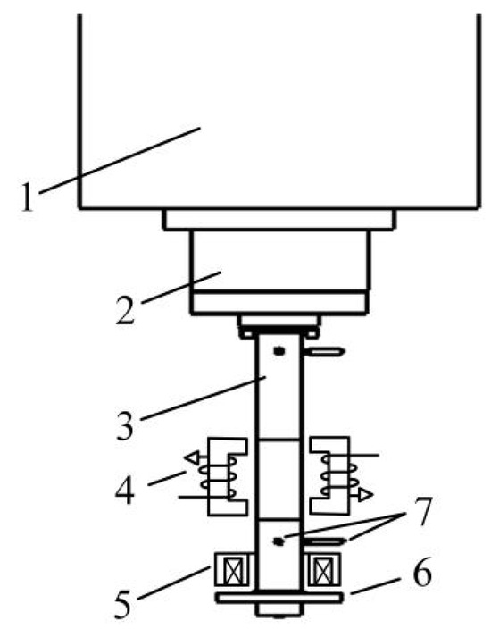
Figure 1.
On-line magnetic non-contact excitation method and testing principle of electric spindle bearing. 1—electric spindle housing; 2—electric spindle; 3—test rod; 4—radial excitation structure; 5—axial excitation structure; 6—axial drive disk; 7—displacement sensor.
Figure 1 illustrates the configuration where the tool handle replaces the original test rod, mounting securely onto the tapered collet at the spindle’s terminal end through an internal drawbar mechanism within the electric spindle. Both radial and axial actuation systems are integrated at the spindle’s extremity, with the axial drive disc firmly attached to the test rod’s tip. During operation, the radial excitation mechanism exerts X- and Y-direction electromagnetic forces upon the test rod, while the axial excitation system applies Z-axis electromagnetic loading to the disc coupled with the test rod’s end. Displacement sensors precisely monitor the test rod’s dynamic response. Notably, both radial and axial loadings employ non-contact excitation methodologies, enabling synchronous real-time measurement of forces and displacements within the rotating electric spindle bearing system.
2.2. Radial Magnetic Excitation Structure
The radial magnetic excitation structure is shown in Figure 2. This structure mainly consists of test rods, silicon steel sheets, stator cores and coils wound around the stator cores, etc. The polarity of the magnetic poles is arranged in the shape of “-N-S-S-N-N-N-S-S-S-N-”, and the coils on two adjacent magnetic poles are connected in series to form magnetic pole pairs. When current enters the coil, magnetic pole pairs are formed. A closed magnetic circuit as shown in Figure 2 will be generated between the silicon steel sheet, the stator core and the air gap, thereby achieving the radial load excitation of the stator core on the test rod. The electromagnetic force of a closed magnetic circuit is determined based on the calibration relationship between the coil current and force, and its calculation formula is as follows:
where, is the vacuum permeability; is the cross-sectional area of the magnetic circuit, equal to the cross-sectional area of the air gap or a single magnetic pole; is the number of turns of the magnetic pole to the coil; is the current in the coil; is half of the angle between two adjacent magnetic poles; is the size of the air gap between the stator core and the loading rod.
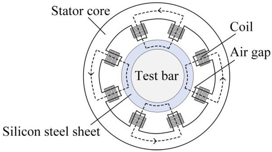
Figure 2.
Structure and principle of radial magnetic excitation.
The structure and material composition of the test rod are illustrated in Figure 3. The primary material of the test rod is 20CrMnTi magnetic steel. To enhance thrust density, load-bearing capacity and measurement accuracy while minimizing hysteresis and eddy current losses, 0.35 mm silicon steel sheets with high magnetic permeability and low iron loss are interference-fitted around the circumference of the test rod. Additionally, 45# steel is interference-fitted at the test rod’s end to serve as the measurement point for the electric spindle’s displacement response.
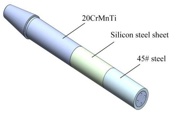
Figure 3.
Test bar structure diagram.
2.3. Axial Magnetic Excitation Structure
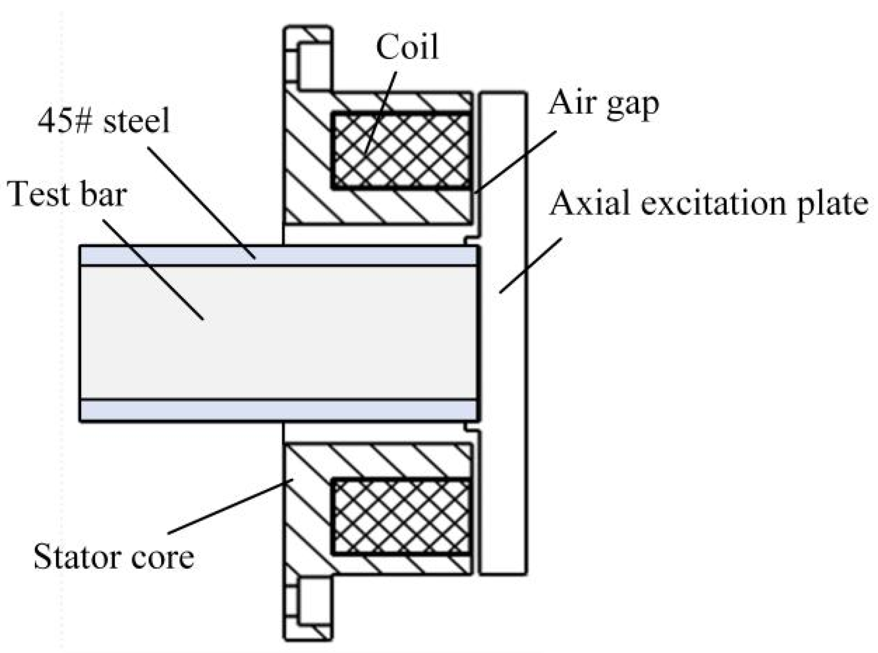
As shown in Figure 4, the axial magnetic excitation structure mainly consists of a test rod, stator core, coil wound on the stator core, axial excitation disc, etc. When the current is passed into the coil, a closed magnetic circuit will be generated between the test rod, stator core, axial excitation disc and the air gap, so as to realize the axial load excitation of the stator core to the axial excitation disc and then to the test rod.
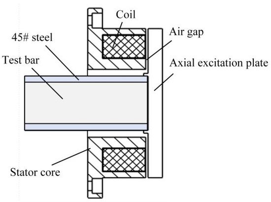
Figure 4.
Structure and principle of axial magnetic excitation.
2.4. Cooling Structure Design
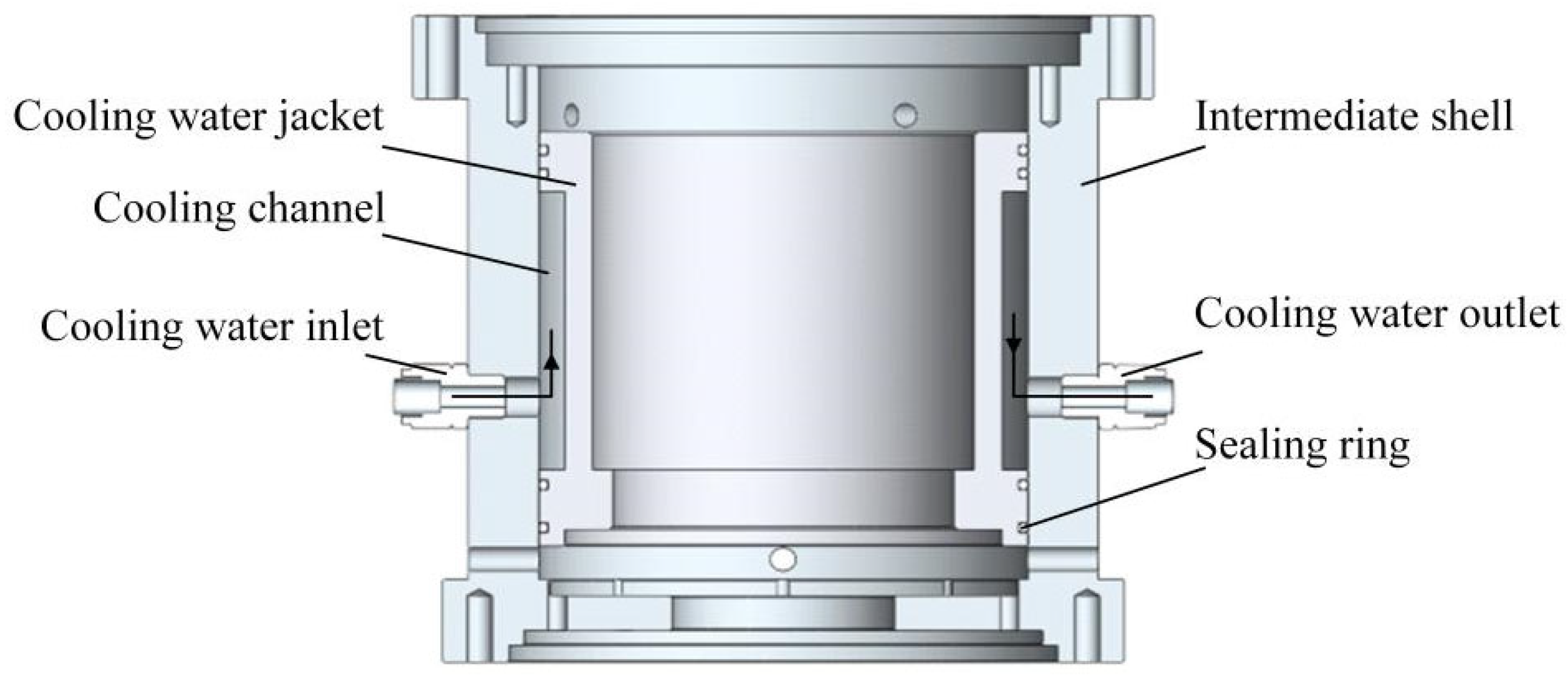
The radial and axial incentive cooling structure illustrated in Figure 5 primarily comprises an intermediate shell, a cooling water jacket, a locking gland and sealing rings. The cooling water jacket is sealed between the intermediate shell and the cooling water jacket to form a cooling channel, with sealing rings providing leakage prevention. The circulating cooling water enters this channel through the locking gland (Port No. 1) and exits via the locking gland (Port No. 2). This cooling system aims to mitigate the effects of stator core vortex heating and other thermal sources on testing accuracy, ensuring sustained stable operation of the magnetic excitation device over extended periods.
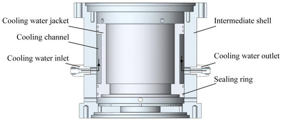
Figure 5.
Cooling structure.
2.5. Sensor Position Layout and Support Structure Design
The installation position of the sensor on the test rod is shown in Figure 6. Sensor No. 1 and sensor No. 2 are arranged at 90°, consistent with the X direction and Y direction of the machine table, respectively, and are installed near the end face of the electric spindle. Sensor No. 3 and sensor No. 4 are also arranged at 90°, in the same X and Y directions as the machine table, and are installed near the end of the test rod.
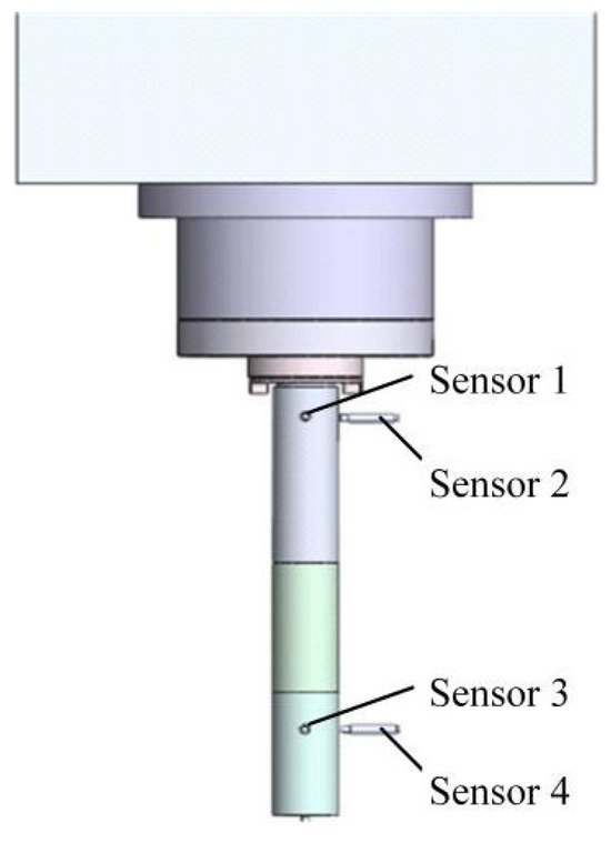
Figure 6.
Schematic diagram of installation position of test rod and sensor.
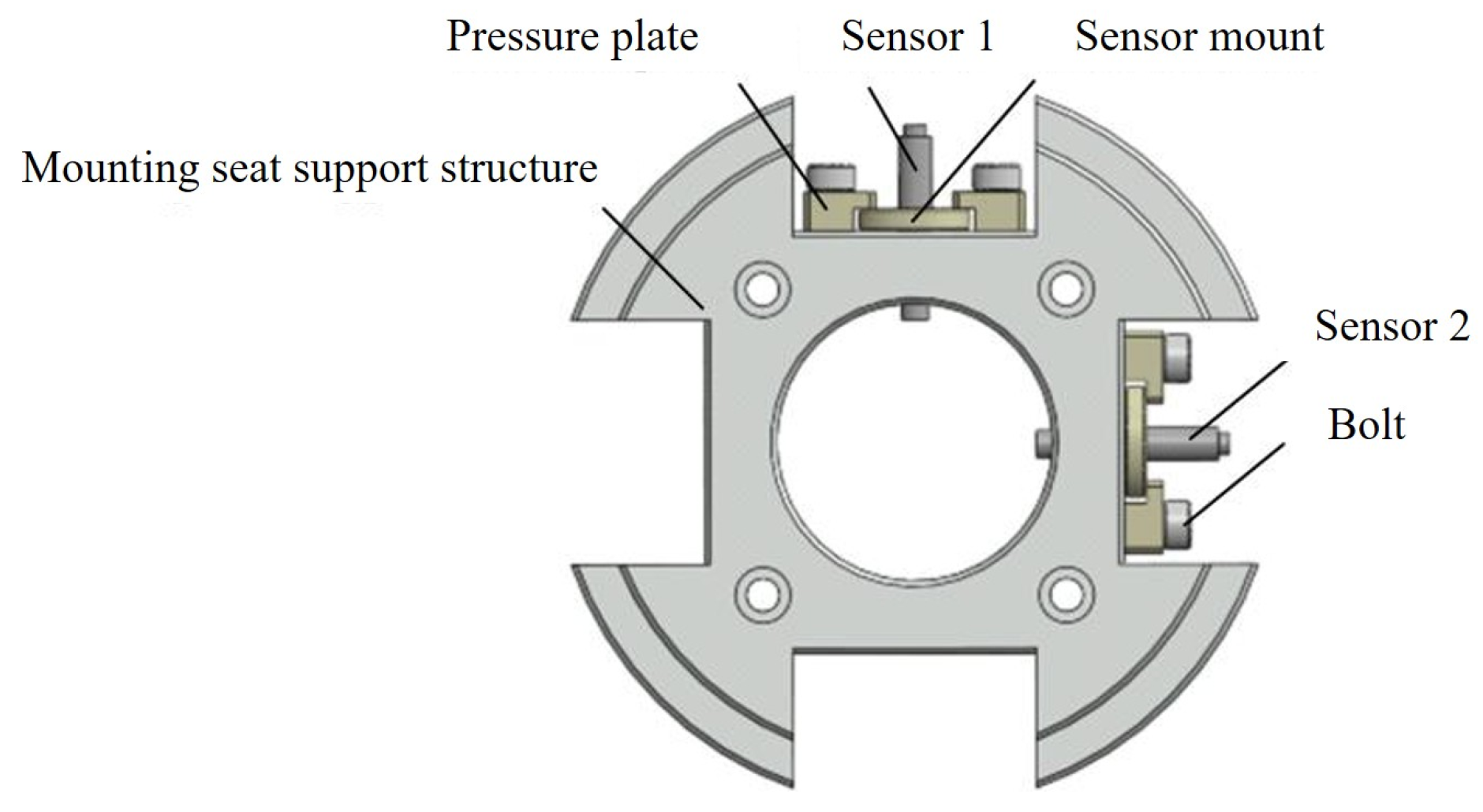
The support structure of the sensor, illustrated in Figure 7, primarily comprises a sensor mounting seat, pressure plate, bolts and the mounting seat’s supporting framework. The annular structure features an inner circumference coaxially aligned with the test rod and an outer circumference coaxially aligned with the testing device. Four radially distributed grooves, positioned at 90° intervals around the central axis, are designed to accommodate displacement sensors. During assembly, displacement sensors are first mounted onto the sensor mounting seat, after which the pressure plate is secured within the grooves using bolts, completing the installation sequence.

Figure 7.
Displacement detection module.
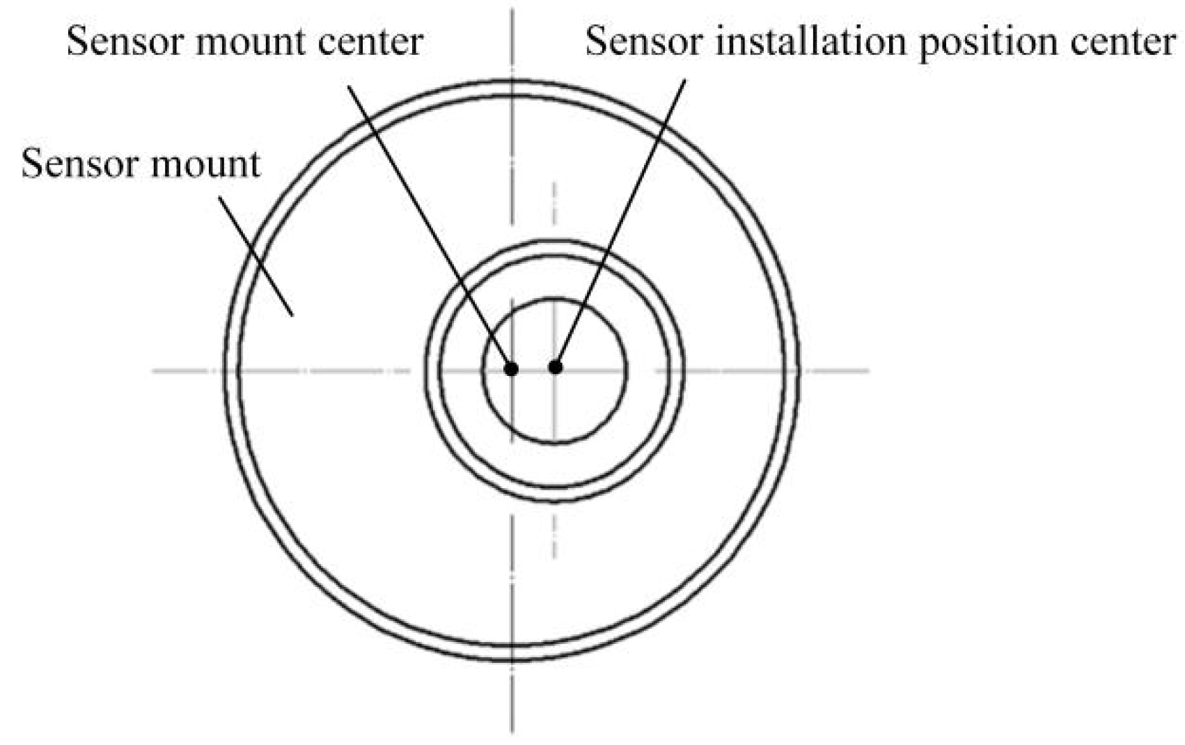
The structure of the displacement sensor mounting seat is shown in Figure 8. The sensor mounting seat adopts an eccentric structure, and the center of the sensor mounting position has an eccentric distance of 1.5 mm relative to the center of the sensor mounting seat. The displacement adjustment can be realized in the peripheral direction of the sensor by 3 mm, and the influence of the sensor installation error on the test accuracy can be reduced by displacement adjustment.

Figure 8.
Structure drawing of sensor mounting seat.
2.6. Overall Structural Design of Test Device
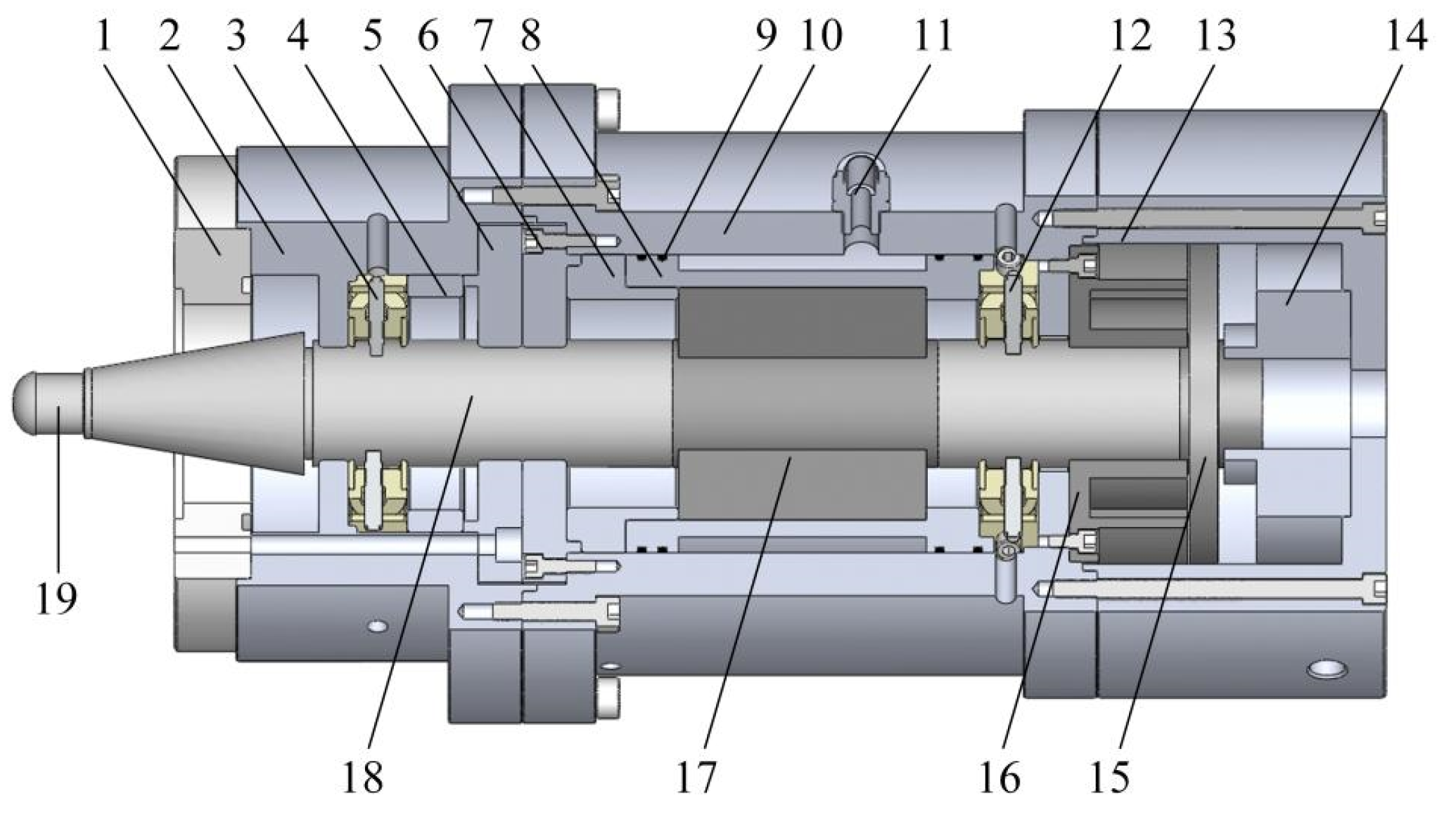
The overall structure of the designed magnetic non-contact excitation and test device is shown in Figure 9. The entire test device connects to the electric spindle via the upper connecting body housing, while avoiding interaction with the feed system, workbench and other machine tool components. This isolation ensures that measurements are not affected by other functional parts of the machine tool. The integrated hollow shaft incremental encoder enables dual measurement functions: tracking the number of rotational cycles of the test rod and quantifying the data collected by the sensor. Specifically, the encoder’s outer ring is securely fixed within the lower connecting body housing, whereas its inner ring engages with the axial drive disk, rotating synchronously with the test rod.

Figure 9.
Structure diagram of magnetic non-contact excitation device. 1—Spindle body shaft end; 2—upper connecting body shell; 3—upper radial displacement detection module; 4—upper connector spacer ring; 5—the end cover of the connecting body housing; 6—intermediate shell end cover; 7—intermediate spacer ring; 8—water jacket; 9—sealing ring; 10—intermediate shell; 11—lock mother straight through; 12—lower radial displacement detection assembly; 13—lower connecting body housing; 14—hollow shaft incremental encoder; 15—axial drive disk; 16—axially excited stator core; 17—radial excitation stator core; 18—optimized test rod; 19—pull the nail.
3. Stiffness Test and Test Data Analysis of Electric Spindle
3.1. Electric Spindle Stiffness Test System Platform Construction
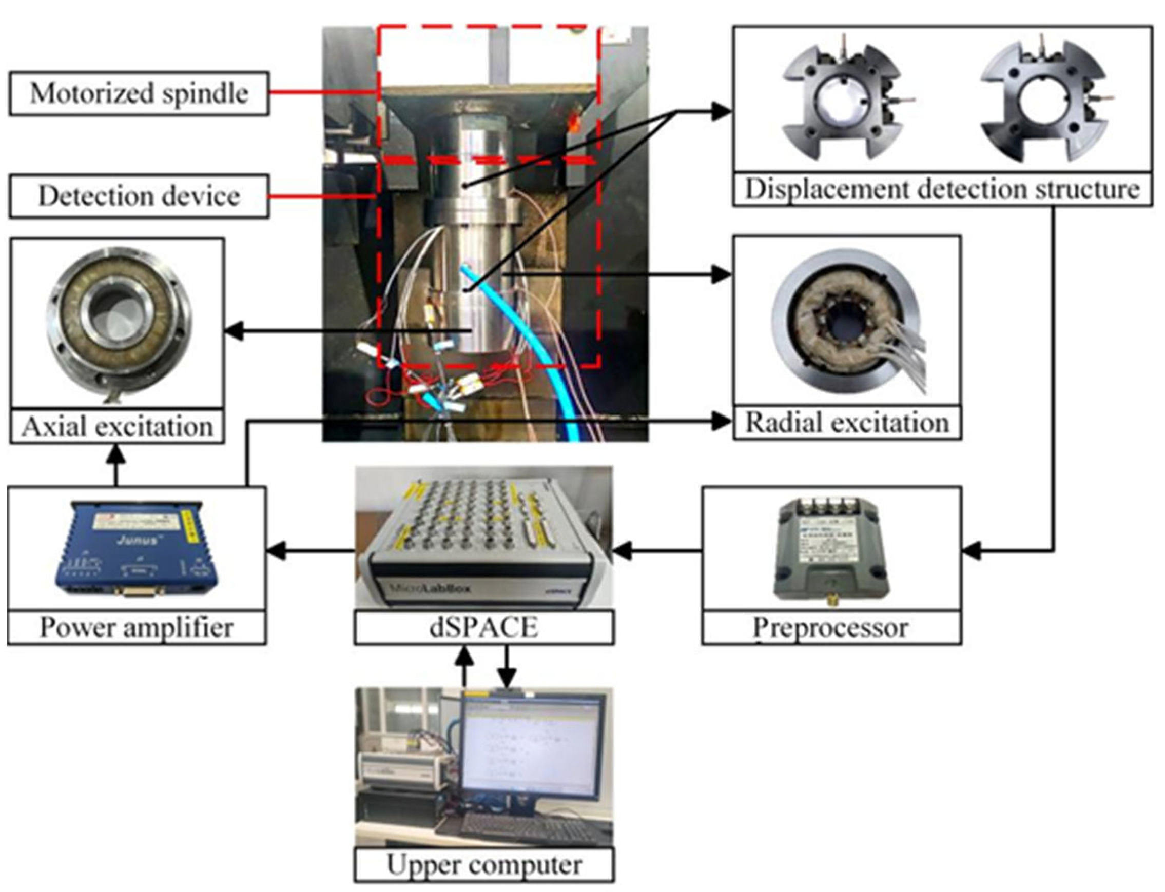
Figure 10 shows the overall test platform of the electric spindle stiffness test system, in which the magnetic non-contact excitation device is coaxially installed on the electric spindle, and the displacement signal of the test rod is transmitted by the built-in sensor to the dSPACE test and analysis system. dSPACE adjusts the control current of the radial and axial excitation structure through the power amplifier. Thus, stable excitation of the test rod by an excitation device is realized. During the test, dSPACE and the host computer collected and analyzed the displacement signal of the test rod in real time, so as to realize the test of the dynamic support stiffness of the electric spindle bearing. The force sensor was employed to calibrate the current–force curve, which enables quantitative determination of the applied force based on the coil current. The process employed quasi-static loading (DC electromagnetic force) with a spindle speed range of 0–24,000 rpm and axial/radial loads of 0–1000 N.

Figure 10.
Working principle diagram of magnetic non-contact excitation device testing system.
3.2. Test and Calculation Method of Support Stiffness of Electric Spindle Bearing
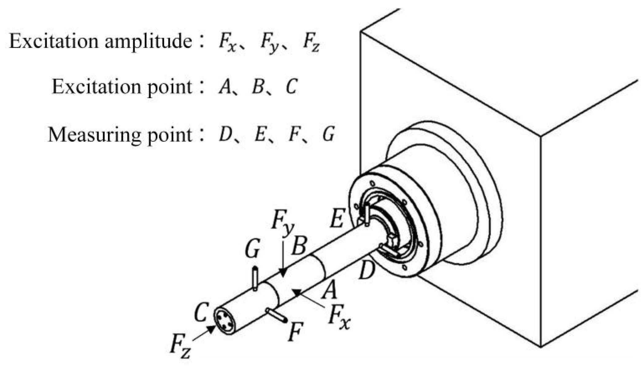
In order to test the stiffness of the electric spindle bearings under actual working conditions, it is necessary to apply load excitation to the electric spindle in the rotating state and measure the displacement response of the electric spindle. The load of the electric spindle tested in this paper is A slowly changing load, that is, the measurement method is quasi-static testing, as shown in Figure 11. The directions of the load excitation point and the measurement point are arranged along the three orthogonal directions of radial X/Y and axial Z, with their specific positions shown in Figure 11. Among them, point A and point B are radial load excitation points, and their excitation amplitudes are and . Point C is the axial load excitation point, and its excitation amplitude is . Select points D and E near the end face of the main shaft and points F and G near the end face of the test rod as the radial displacement measurement points.

Figure 11.
Schematic diagram of the position and direction of the excitation point and the measuring point of the dynamic bearing stiffness test of the electric spindle.
The dynamic support stiffness of the electric spindle bearing can be calculated based on the applied excitation load and the corresponding displacement response. The stiffness is calculated by applying a specific incremental force and recording the corresponding displacement, and multiple measurements are conducted to ensure accuracy. The relationship between the excitation load and the displacement is shown in Equation (2):
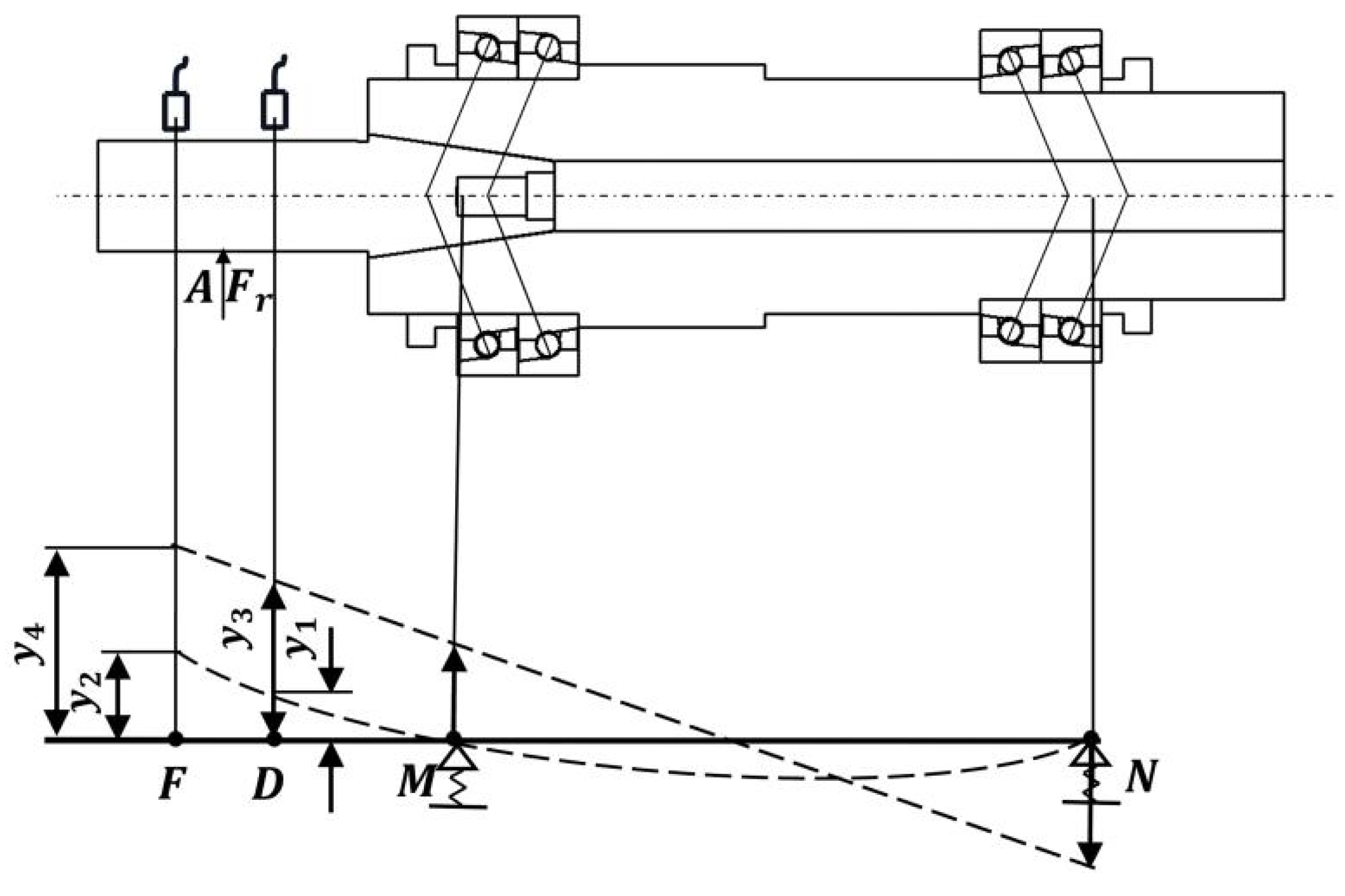
where, J is the dynamic support stiffness of the bearing, ΔF is the load change within a period of time; ΔX is the change in displacement corresponding to the change in load. Figure 12 shows the equivalent model of the bearing-test rod system under external load, where the test rod and the spindle are connected through a conical joint surface to form a bearing-test rod system.
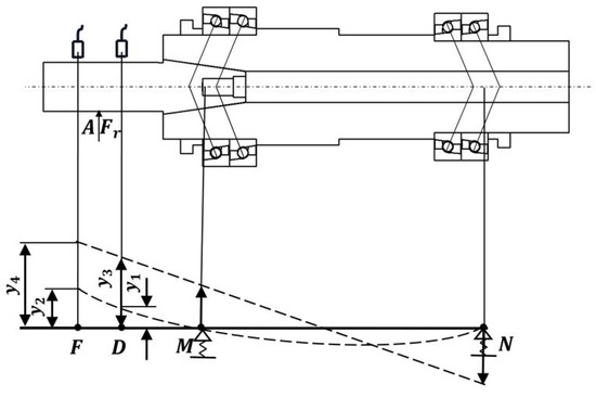
Figure 12.
Test rod-shaft-bearing equivalent model.
As shown in Figure 12, in the equivalent model, both the NM segment and MF segment are beam elements. When the electric spindle bearing is assumed to be rigid and the NF segment is flexible, the bearing has no radial displacement and deflection deformation, and the deflection curve of the NF segment is shown as the dotted curve of the NF segment. In this case, the displacement of measuring point D and measuring point F are represented by and , respectively. When the electric spindle bearing is assumed to be elastic and the NF segment is rigid, there is no bending deformation in the NF segment, and the displacement generated by the NF segment under the elastic support of the bearing is shown as the straight line at the point of the NF segment. At this time, the displacement at the measuring point D and the measuring point F are represented by and , respectively.
The model of the front support bearing of the electric spindle of the experimental vertical machining center is NTN 7014UCG/GLP4, and the main technical parameters are shown in Table 1. The model of the rear support bearing is NTN 7012UCG/GLP4, and the main technical parameters are shown in Table 2. The pre-tightening method of the front and rear support bearings is positioning pre-tightening, and the pre-tightening grade is light positioning pre-tightening.

Table 1.
NTN 7014UCG/GLP4 bearing parameters.
Table 2.
NTN 7012UCG/GLP4 bearing parameters.
As can be seen from Figure 12, the tested electric spindle bearings are series-type back-to-back combinations, namely the QBC combination, and the measured support stiffness of the front and rear bearings is twice that of a single bearing.
According to the force balance condition, the forces and transmitted by the radial load to the rear bearing and front bearing are:
Displacement and at measuring points D and F can be expressed as follows:
According to the deflection curve of the rotating shaft under the action of , the expressions of and are as follows:
where, is the equivalent moment of inertia of the rotating shaft, and since the rotating shaft of the electric spindle is a ladder shaft structure, then . Where is the equivalent diameter of the rotating shaft, expressed as follows:
where, and are the length and diameter of the step shaft in the section, respectively, and and are the length of the rotating shaft and the total number of step axes, respectively.
Through the geometric relationship can be obtained:
In the formula, and are the displacement response of point M and point N under the excitation of and , respectively, that is, the displacement amount of the front and rear support bearings, which can be obtained through the joint vertical Formulas (4) and (7). The supporting stiffness of the front and rear bearings of the electric spindle can be obtained by combining Formula (2).
4. Discussion
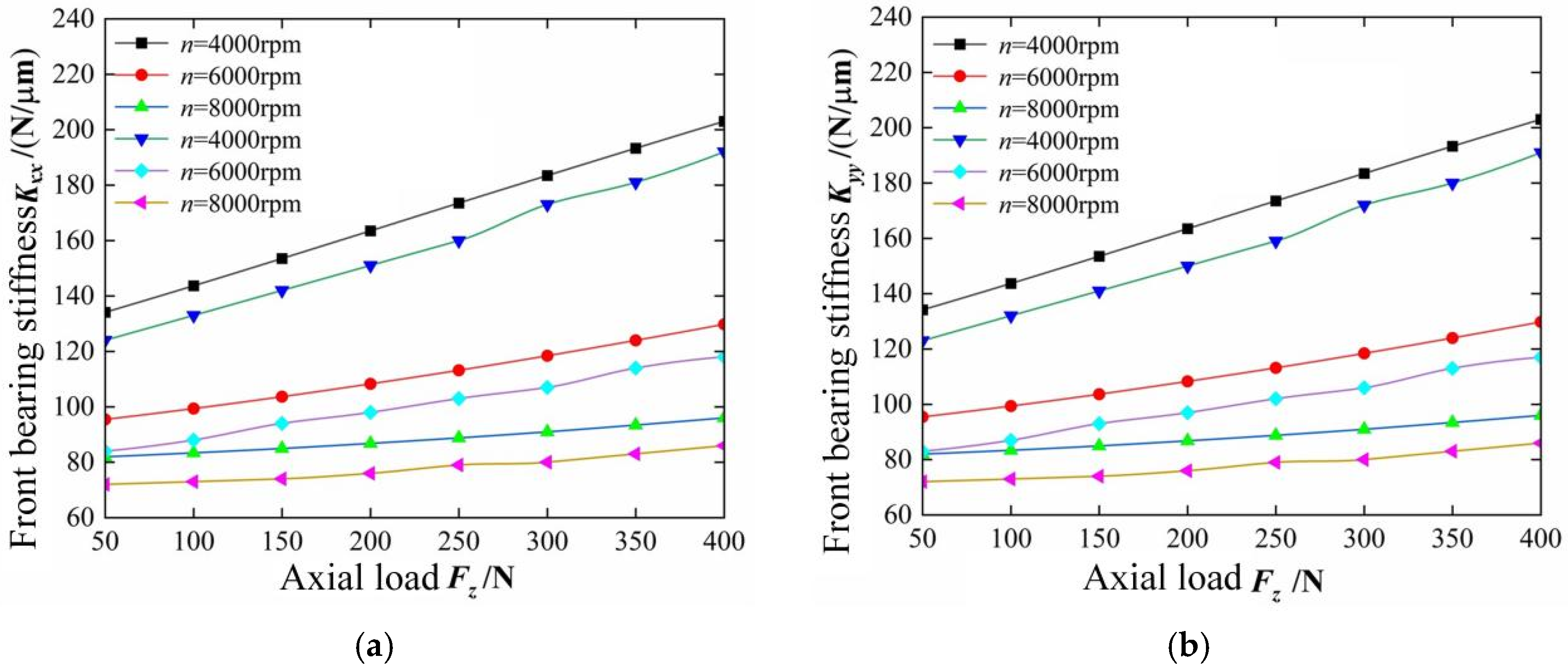
The test mainly studies the influence of axial and radial loads on the stiffness of electric spindle bearings in the X and Y directions under rotating conditions. As shown in Figure 13 and Figure 14, the influences of axial load and rotational speed on the stiffness of the front and rear bearings of the electric spindle under the conditions of radial load and , respectively.
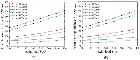
Figure 13.
The influence of rotational speed and axial excitation on the stiffness of front bearing (a) The variation of the front bearing stiffness Kxx with the change of axial force Fz; (b) The variation of the front bearing stiffness Kyy with the change of axial force Fz.
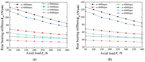
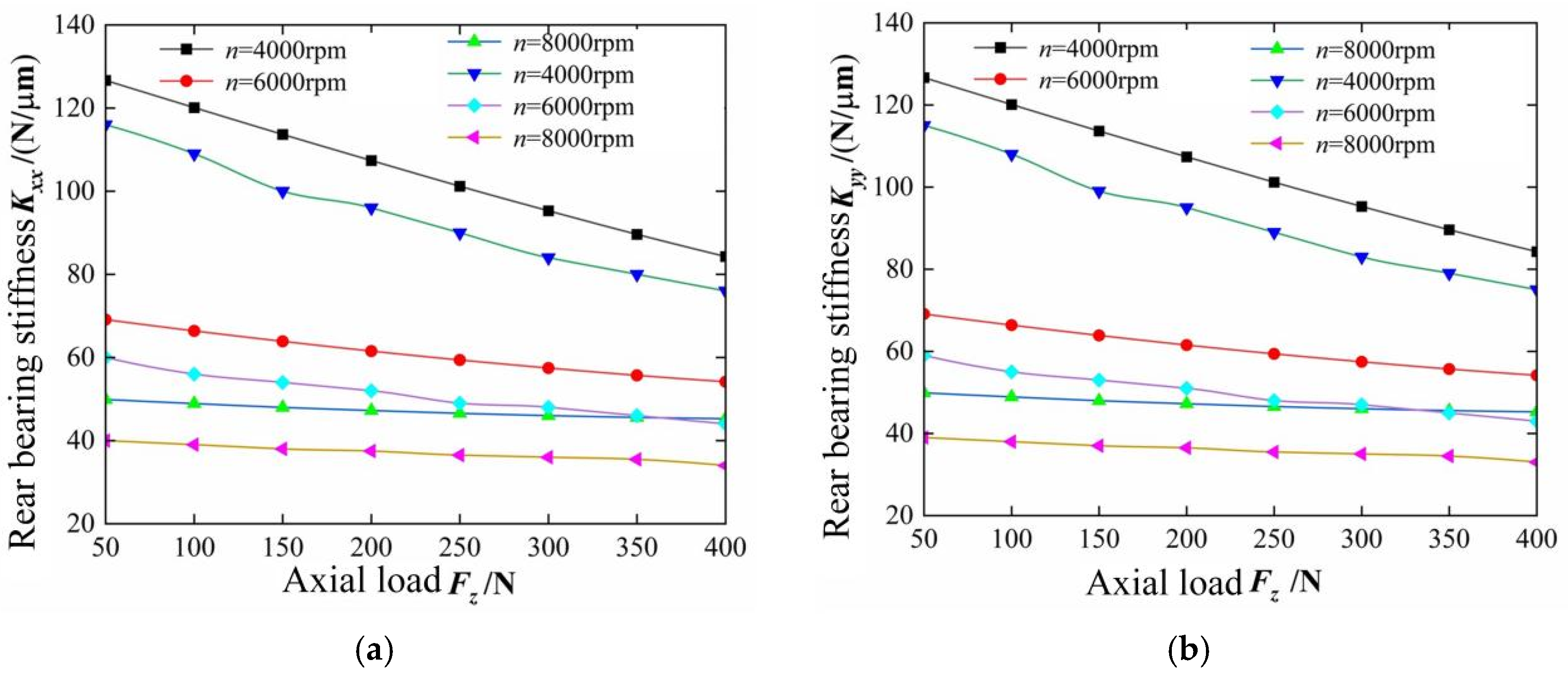
Figure 14.
The influence of rotational speed and axial excitation on rear bearing stiffness (a) The variation of the rear bearing stiffness Kxx with the change of axial force Fz; (b) The variation of the rear bearing stiffness Kyy with the change of axial force Fz.
As shown in Figure 13 and Figure 14, when the speed remains unchanged, the front bearing X and Y-direction support stiffness of the electric spindle is positively correlated with the axial load , while the rear bearing X and Y-direction support stiffness is negatively correlated with the axial load . For example, at a rotational speed of 6000 rpm with the conditions of radial load and , respectively, when the axial force Fz increases from 50 N to 400 N, the Kxx of the front bearing increases by 42.2%, and the Kyy increases by 43.9%; while the Kxx of the rear bearing decreases by 25.3%, and the Kyy decreases by 29.1%. When the axial load remains unchanged, the X and Y bearing stiffness of the front and rear bearings of the electric spindle are negatively correlated with the speed . When the speed is low, the negative correlation degree between the bearing stiffness and the speed is large, and the negative correlation degree between the bearing stiffness and the speed is gradually weakened with the speed increasing. With the gradual increase of speed , the effect of axial load on the bearing stiffness is gradually weakened. The stiffness obtained by the test is less than the theoretical value, and the changing trend of the two is basically consistent.
Axial loads tend to increase the contact area between the rolling elements and the inner raceway and the stiffness of the bearing support. When the electric spindle is subjected to axial load, the front bearing bears most of the axial load. As the axial load of the front bearing increases, the axial load of the rear bearing gradually decreases [15] When the electric spindle operates at high speed, the rolling elements approach the outer raceway under the action of centrifugal force. The contact angle between the rolling elements and the inner raceway increases, and the contact load decreases, resulting in the softening of the bearing stiffness. Meanwhile, the contact angle between the rolling elements and the outer raceway decreases, and the contact load increases, resulting in an increase in the axial load of the outer ring. To a certain extent, this inhibits the softening of the bearing stiffness. Therefore, the stiffness of the bearing support will gradually decrease as the rotational speed increases, but the decreasing trend will gradually slow down. During the process of increasing rotational speed, the dominant effect of axial load on the bearing support stiffness gradually changes to the dominant effect of rotational speed on the bearing support stiffness. Another reason is that when the axial load is low, the number of micro-convex body contacts on the surface of the rolling elements inside the bearing is small, and the contact area is also small, so the dynamic support stiffness is relatively low. When the axial load increases, the number of micro-convex bodies in contact inside the bearing increases. The micro-convex bodies that have been in contact undergo compressive deformation under the action of the axial force, and the actual contact area increases. Therefore, the dynamic support stiffness gradually increases.
Therefore, as the rotational speed increases, the positive correlation between the bearing support stiffness and the axial load gradually weakens. The test results of bearing support stiffness are in good agreement with the theoretical calculation results. However, due to the conical connection between the test rod and the rotating shaft, the overall stiffness of the bearing-test rod system is reduced to a certain extent, and the displacement of the test rod detected by the sensor is increased. Therefore, the test-measured value of the bearing support stiffness is lower than the theoretically calculated value.
As shown in Figure 15 and Figure 16, under the condition of axial load , the radial load , and speed influence the supporting stiffness of the front bearing and rear bearing of the electric spindle, respectively.
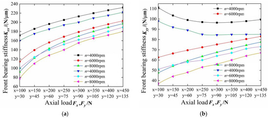
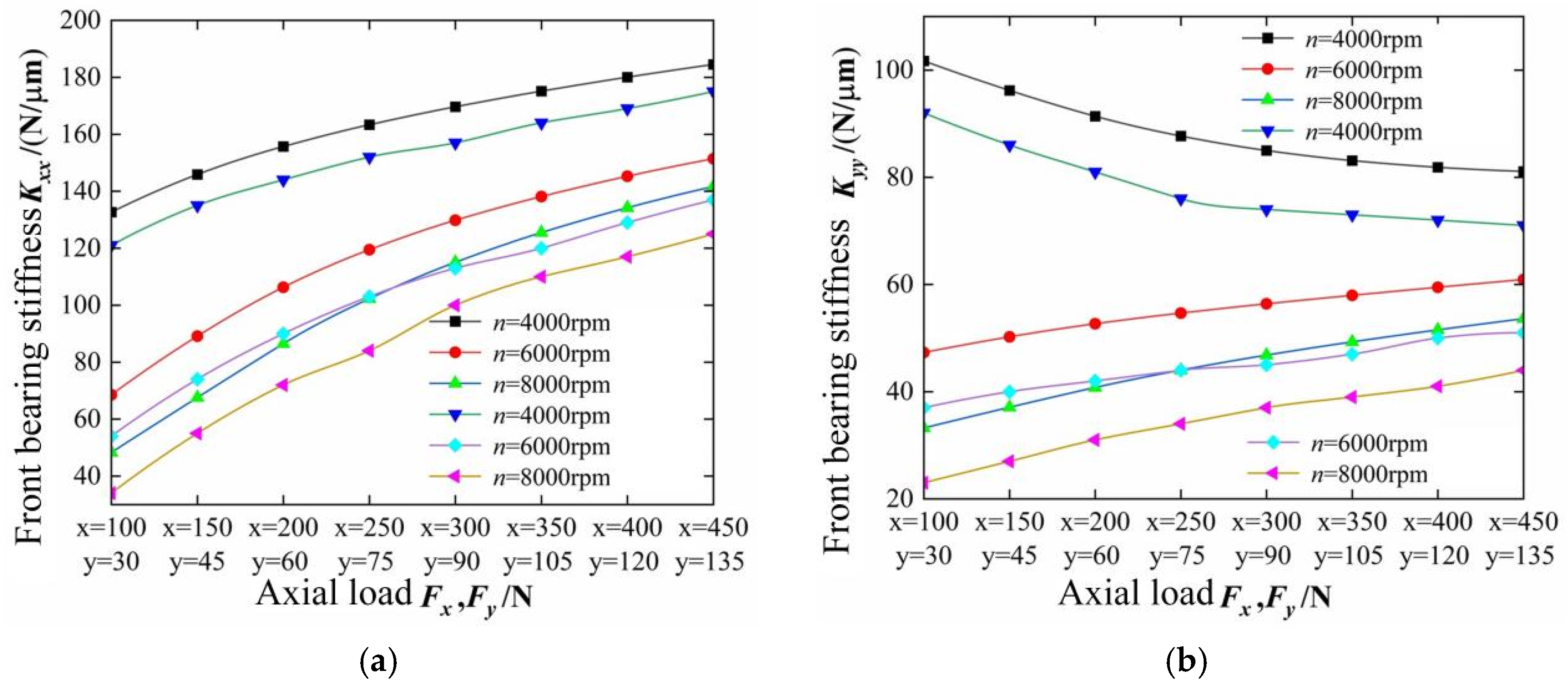
Figure 15.
The influence of rotational speed and radial excitation on the stiffness of front bearing (a) The variation of the front bearing stiffness Kxx with the change of axial force Fx,Fy; (b) The variation of the front bearing stiffness Kxx with the change of axial force Fx,Fy.
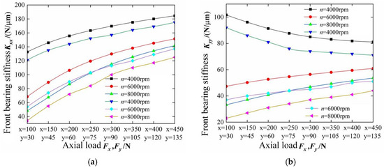
Figure 16.
The influence of rotational speed and radial excitation on rear bearing stiffness (a) The variation of the rear bearing stiffness Kxx with the change of axial force Fx,Fy; (b) The variation of the rear bearing stiffness Kxx with the change of axial force Fx,Fy.
Figure 15 and Figure 16 illustrate that at constant rotational speed, the electric spindle’s front/rear bearing X-direction stiffness increases with radial load, consistently exceeding Y-direction stiffness. At low speeds, Y-stiffness shows an inverse correlation with radial load, transitioning to a direct correlation at higher speeds. With fixed radial load, both X/Y stiffness decrease as speed rises, though this negative correlation weakens under larger loads. Front and rear bearings exhibit identical stiffness trends, yet the front bearing maintains superior radial support compared to the rear.
As radial load Fx increases, the X-direction contact load grows, establishing it as the primary load-bearing zone with enhanced stiffness. Due to unbalanced loading, X-direction stiffness consistently exceeds Y-direction stiffness. At low rotational speeds, Y-direction stiffness decreases with rising load; however, at higher speeds, centrifugal force strengthens rolling element contact with the outer race, increasing Y-direction load and stiffness. Conversely, centrifugal force reduces contact between rolling elements and the inner race, lowering overall radial stiffness. This stiffness-softening effect weakens under higher radial loads. The front bearing exhibits greater stiffness than the rear due to its larger size, increased preload under axial load, and reduced rear bearing preload. These combined effects result in distinct stiffness characteristics between axes and bearing positions.
5. Conclusions
To address the difficulty in testing the dynamic support stiffness of electric spindles under rotating conditions, an online testing device for the dynamic support stiffness of electric spindles under high-speed rotation was developed. The test results of the preloaded combined bearings under combined loads were analyzed. The main conclusions are as follows:
- (1)
- The support stiffness of the front and rear bearings of the electric spindle increases with the increase in radial load, and the phenomenon of dynamic support stiffness “softening” caused by increasing rotational speed can be suppressed to some extent.
- (2)
- As the rotational speed of the electric spindle increases, the support stiffness of the front and rear bearings exhibits a reduction in stiffness. Under the influence of centrifugal force and inner ring expansion, the increase in rotational speed nonlinearly enlarges the contact angle and contact load between the rolling elements and the inner/outer raceways. However, the axial component of the contact load can partially counteract the stiffness “weakening” phenomenon caused by the increase in rotational speed.
- (3)
- An increase in axial load raises the preload on the front and rear bearings, enlarging the contact area between the rolling elements and the micro-convexities of the inner/outer raceways. Consequently, the dynamic support stiffness of the combined bearings improves, significantly mitigating the “softening” effect of the electric spindle’s dynamic support stiffness as rotational speed increases.
The non-contact online testing device for electric spindle bearing stiffness developed in this study can effectively measure the dynamic stiffness of electric spindles under high-speed rotation. However, this paper only provides a preliminary analysis of the test results and overlooks the dynamic characteristic changes caused by the conical interface between the spindle and tool holder. Future research will focus on improving measurement accuracy and establishing a digital twin model for spindle operation.
Author Contributions
Conceptualization, C.C., L.Z. and C.H.; methodology, L.Z.; software, Q.M.; validation, Q.M.; formal analysis, Q.M.; investigation, J.S.; resources, Z.L.; data curation, Z.L.; writing—original draft preparation, C.C., L.Z. and C.H.; writing—review and editing, C.C., L.Z. and J.S.; visualization, J.S.; supervision, J.S.; project administration, C.C.; funding acquisition, Z.L. All authors have read and agreed to the published version of the manuscript.
Funding
This work was supported in part by the Research on Reliability Growth Theory and Accelerated Test Methods for Large Precision Gantry Machining Centers (Grant No. U22B2087).
Data Availability Statement
The raw data supporting the conclusions of this article will be made available by the authors upon request.
Acknowledgments
In this study, we have received a great deal of valuable support, for which we express our sincere gratitude. Special thanks go to Shenyang Machine Tool Co., Ltd. for their administrative and technical support, which has greatly enhanced the efficiency and quality of our research.
Conflicts of Interest
Liang Zhang was employed by the company Shenyang Machine Tool Co., Ltd., Chunlei Hua was employed by the company General Technology Group Machine Tool Engineering Research Institute Co., The remaining authors declare that the research was conducted in the absence of any commercial or financial relationships that could be construed as a potential conflict of interest.
References
- Huang, T.; Luo, G.; Su, W.; Che, C.; Shi, J. Test method for Dynamic Characteristics of Rolling Bearing. Vib. Test Diagn. 1996, 16, 33–39. [Google Scholar] [CrossRef]
- Yun, X.; Mei, X.; Jiang, G.; Li, Y.; Yuan, S. Dynamic Stiffness Analysis and Test Method of Angular Contact Ball Bearing for High Speed spindle. Vib. Test Diagn. 2019, 39, 892–897+912. [Google Scholar] [CrossRef]
- Jia, Q.; Ouyang, W.; Zhang, X.; Yuan, X. Research on Magnetic Force Loading Excitation Technology for Stiffness Testing of Water-lubricated Bearing. Mach. Des. Manuf. 2014, 99–101. [Google Scholar] [CrossRef]
- Jin, X.; Li, B. Calculation and Measurement Method of Dynamic Stiffness of High Speed electric spindle. Mod. Manuf. Eng. 2016, 40–45+68. [Google Scholar] [CrossRef]
- Fan, C.C.; Pan, M.C. Experimental study on the whip elimination of rotor-bearing systems with electromagnetic exciters. Mech. Mach. Theory 2011, 46, 290–304. [Google Scholar] [CrossRef]
- Garrick, I.E.; Watkins, C.E. A Theoretical Study of the Effect of Forward Speed on the Free-Space Sound-Pressure Field Around Propellors; NACA Report 1198; NASA: Washington, DC, USA, 1954. [Google Scholar]
- Zhang, X.; Han, Q.; Peng, Z.; Chu, F. A comprehensive dynamic model to investigate the stability problems of the rotor–bearing system due to multiple excitations. Mech. Syst. Signal Process 2016, 70–71, 1171–1192. [Google Scholar] [CrossRef]
- Meng, J.; Chen, X.; Kang, H.; Chen, F. Study on Loading test of high-speed electric spindle. J. Mech. Strength 2009, 31, 689–692. [Google Scholar] [CrossRef]
- Aggarwal, S.; Nešić, N.; Xirouchakis, P. Cutting torque and tangential cutting force coefficient identification from spindle motor current. Int. J. Adv. Manuf. Technol. 2013, 65, 81–95. [Google Scholar] [CrossRef]
- Feng, M.; Zhao, Y.; Yang, W.; Chen, F. Development of Non-contact gas Film loading Stiffness Test bench for High Speed spindle. Mach. Des. Manuf. 2013, 102–105. [Google Scholar] [CrossRef]
- Matsubara, A.; Yamazaki, T.; Ikenaga, S. Non-contact measurement of spindle stiffness by using magnetic loading device. Int. J. Mach. Tools Manuf. 2013, 71, 20–25. [Google Scholar] [CrossRef]
- Ma, R. Research on Stiffness Characteristics and Test Methods of Machine Tool Under Spindle Rotation; Tsinghua University: Beijing, China, 2018. [Google Scholar] [CrossRef]
- Yu, Y.; Karimi, H.R.; Gelman, L.; Liu, X. A novel digital twin-enabled three-stage feature imputation framework for non-contact intelligent fault diagnosis. Adv. Eng. Inform. 2025, 66, 103434. [Google Scholar] [CrossRef]
- Tuninetti, V.; Alzugaray, R.; González, J.; Valenzuela, M.; Jaramillo, A.; Diez, E. Root cause and vibration analysis to increase veneer manufacturing process efficiency: A case study on an industrial peeling lathe. Eur. J. Wood Wood Prod. 2021, 79, 951–966. [Google Scholar] [CrossRef]
- He, P.P.; Gao, F.; Li, Y.; Wu, W.W.; Zhang, D.Y. Study on thermo-mechanical coupling characteristics of angle contact ball bearing with fix-position preload. Ind. Lubr. Tribol. 2019, 71, 795–802. [Google Scholar] [CrossRef]


Disclaimer/Publisher’s Note: The statements, opinions and data contained in all publications are solely those of the individual author(s) and contributor(s) and not of MDPI and/or the editor(s). MDPI and/or the editor(s) disclaim responsibility for any injury to people or property resulting from any ideas, methods, instructions or products referred to in the content. |
© 2025 by the authors. Licensee MDPI, Basel, Switzerland. This article is an open access article distributed under the terms and conditions of the Creative Commons Attribution (CC BY) license (https://creativecommons.org/licenses/by/4.0/).