Abstract
The rotor shaft is a critical component responsible for transmitting engine power to the helicopter’s rotor. Deformation of the rotor shaft can affect the meshing performance of the output stage gears in the main gearbox, thereby affecting load transfer efficiency. By adjusting the support parameters of the rotor shaft, deformation at critical positions can be minimized, and the meshing performance of the output stage gears can be improved. Therefore, it is imperative to investigate the influence of rotor shaft support parameters on the deformation of the rotor shaft. This paper takes coaxial reversing dual rotor shaft (CRDRS) support configuration with intermediate bearing support as object. Utilizing Timoshenko beam theory, a rotor shaft model is developed, and static equations are derived based on the Lagrange equations. The relaxation iteration method is employed for a two-level iterative solution, and the effects of bearing support positions and support stiffness on the radial and angular deformations of rotor shaft gears under two support configurations, simply supported outer rotor shaft–cantilever-supported inner rotor shaft, and simply supported outer rotor shaft–simply supported inner rotor shaft, are analyzed. The findings indicate that the radial and angular deformations of gear s1 are consistently smaller than those of gear s2 in the CRDRS system. This difference is particularly pronounced in the selection of support configuration. The bearing support position plays a dominant role in gear deformation, exhibiting a monotonic linear relationship. In contrast, although adjustments in bearing support stiffness also follow a linear pattern in influencing deformation, their impact is relatively limited. Overall, optimal design should prioritize the adjustment of bearing positions, particularly the layout of b3 relative to s2, while complementing it with coordinated modifications to the stiffness of bearings b2, b3, and b4 to effectively enhance the static characteristics of the dual-rotor shaft gears.
1. Introduction
A rotor shaft is a crucial component of a helicopter. On the one hand, it transmits the power generated by the engine to the rotor; on the other hand, it withstands the thrust, tangential force, torque, and bending moment generated by the rotor. The deformation of the rotor shaft affects the meshing performance of the output stage gears. This can be explained from two aspects. Firstly, the deflection of the rotor shaft at the gear location can influence the gear meshing clearance, impacting the dynamic performance of the gears. Secondly, the existence of sectional angle at the gear location of the rotor shaft can affect the angular misalignment error of gear pair, thereby influencing the contact performance. However, the deflection and sectional angle of rotor shaft at can be improved by adjusting rotor shaft support parameter, thus enhancing the power transmission performance of the helicopter. Therefore, it is necessary to analyze the effect of bearing support parameters on the deflection and sectional angle of the rotor shaft at the gear location.
Typical rotor system support configurations include double-point support [1,2], multi-point support [3,4], rigid bearing support [5], elastic bearing support [6,7,8], and so on. However, the rotor shaft of a coaxial helicopter belongs to a dual-rotor system, where the internal and external shafts are installed on the same axis. The external shaft is typically supported directly by bearings within the casing. The internal shaft, which needs to pass through the external shaft and is usually relatively long, cannot be directly supported by the casing. Therefore, it is typically supported by intermediate bearings or static shaft, supporting the internal rotor shaft on the internal wall of the external rotor shaft or on the static shaft. Thus, the support method must be chosen based on the helicopter’s structural stability and load-bearing requirements, and can be broadly classified into three configurations: support structures with intermediate bearings, support structures without intermediate bearings, and support structures with static standpipe.
References [9,10,11] introduce a CRDRS support structure with intermediate bearings, where the intermediate bearings are installed between the internal and external rotor shafts and close to the upper rotor. References [12,13,14] describe a CRDRS support structure without intermediate bearings, which is similar to the structure with intermediate bearings, except the intermediate bearings are installed at the lower rotor hub position to provide sufficient space for bearing installation. References [15,16] discuss a CRDRS support structure with static shaft. This support structure differs from the above by incorporating a standpipe structure aimed at transmitting bending moments and shear forces, while torque and lift are transmitted through the rotor shaft. Although references [17,18,19] cover coaxial reversing dual rotor shaft supports, they do not provide specific descriptions of the support configurations, making it difficult to determine the rotor shaft support structure.
The support parameters of the rotor shaft, such as support position and support stiffness, influence the bending moment distribution, deformation, and sectional angle of the rotor shaft. However, current research on the design of rotor shaft support parameters is limited, with most studies focusing on the design of rotor system support structures. Hong et al. [20] analyzed the impact of support structure parameters (support position and support stiffness) on the stiffness and dynamic characteristics of rotor systems in high-speed aero-engine rotor systems. Yu et al. [21] investigated the effects of bearing support position and support stiffness on the dynamic characteristics of high-speed flexible rotors with loose supports. Xia et al. [22] established a finite element analysis model for rotor-bearing support systems, analyzing the relationship between support stiffness, bearing vibration, and the vibration response of the shaft. Scholars have also studied the support parameters in dual-rotor systems. Che et al. [23] examined the impact of bearing support position and support stiffness on load distribution and the maximum floating number of gears in dual-rotor systems. Zuo et al. [24] analyzed the influence of support stiffness on the dynamic characteristics of dual-rotor systems. Deng et al. [25] investigated the effects of rolling bearing structural parameters on the dynamic characteristics of dual-rotor systems.
From the aforementioned studies, it can be observed that current research primarily focuses on the dynamics of dual-rotor systems. However, for helicopter rotor shafts, the high load and low-speed conditions mean that dynamic problems are less prominent. Instead, static problems such as rotor shaft deformation and load distribution need more attention. The support parameters of bearings have a significant impact on static characteristics, making it necessary to analyze the influence of bearing support parameters on the static characteristics of coaxial reversing dual rotor shafts.
In this paper, a static model for CRDRS support configuration with intermediate bearing support is established based on the Lagrange equation, and the relaxation iteration method is used to solved it. This method can more accurately and efficiently characterize the influence of bearing parameters on the static characteristics of the system, while effectively reflecting variations in bearing support stiffness. And the effects of bearing support position and support stiffness on the radial and angular deformations of rotor shaft gears under two support configurations: simply supported external rotor shaft–simply supported internal rotor shaft, and simply supported external rotor shaft–cantilever-supported internal rotor shaft are analyzed. This analysis aims to provide guidance and a basis for the support design of rotor shafts.
2. Physical Model of CRDRS Support Configuration with Intershaft Bearing Support
Figure 1 illustrates the static model of the CRDRS system, which comprises the inner rotor shaft, outer rotor shaft, rotor shaft support bearings, and gear components. The outer rotor shaft is configured with a simply supported bearing arrangement. The upper bearing of the gear is a double-row tapered roller bearing, capable of withstanding radial loads, axial loads, and bending moments. The lower section of the gear employs cylindrical roller bearings to support radial loads. A cylindrical roller bearing serves as an intermediate bearing between the inner and outer rotor shafts, with its support positioned near the lower rotor hub. The inner rotor shaft can be supported in either a simply supported or cantilevered arrangement. The bearing type located farthest from the hub is a double-row tapered roller bearing. When this bearing is situated below the inner rotor shaft gear, it forms a simply supported bearing system with the intermediate bearing, as depicted in Figure 1a. Conversely, when this bearing is positioned above the inner rotor shaft gear, it forms a cantilevered bearing system with the intermediate bearing, as shown in Figure 1b. The establishment of the static model for the CRDRS system is based on the development of the overall stiffness matrix. This section initially derives the stiffness matrix for each substructure within the system, followed by the assembly of these substructures to construct the overall system stiffness matrix.
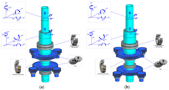
Figure 1.
Three-dimensional diagram of CRDRS system. (a) Simple supported internal rotor shaft configuration. (b) Cantilever-supported internal rotor shaft configuration.
3. The Static Model of CRDRS with Intermediate Bearing Support
3.1. Rotor Shaft Stiffness Model
The rotor shaft is subjected to the combined effects of thrust force, tangential force, bending moment, and torque. Among these, the shear force caused by the tangential force is significant and cannot be neglected. Therefore, this paper utilizes the Timoshenko beam model to analyze the shaft element.
Figure 2 shows the shaft element model. This shaft element is numbered j and contains two nodes, node i and node (i + 1). The length of the element is le, elastic modulus is E, and the mass moment of inertia is Je. Since the rotor load is a six-component force, the shaft element node uses a six-degree-of-freedom model, which can be represented by the following equation.
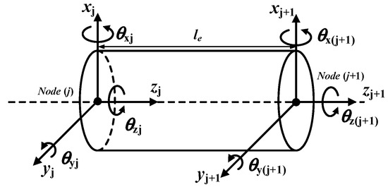
Figure 2.
Shaft element model.
The detailed derivation process of the stiffness matrix for the shaft element can be found in reference [26], and will not be repeated here. After derivation, the stiffness matrix Ke for the shaft element can be obtained which can refer to the Appendix A.
The coaxial high-speed helicopter, characterized by its utilization of rigid rotors, exhibits a substantial escalation in flapping and bending vibration loads on the rotor blades. Consequently, the rotor shaft must exhibit adequate strength, with weight remaining a pivotal design consideration. Hence, titanium alloys present themselves as an optimal material selection. In comparison to conventional steels, titanium alloys can diminish the weight of the rotor shaft by approximately 40% while preserving equivalent strength. Furthermore, the rotor shaft endures intricate cyclic stresses during operation, encompassing bending, torsion, and shear. The superior fatigue resistance of titanium alloys contributes to the enhancement of the component’s service life. In this investigation, TC4 (Ti-6Al-4V) is designated as the material for the rotor shaft. The material properties are delineated in Table 1, while the structural parameters for the inner and outer rotor shafts are comprehensively outlined in Table 2 and Table 3.

Table 1.
TC4 material property parameters.
Table 2.
Structural parameters of the inner rotor shaft.
Table 3.
Structural parameters of the outer rotor shaft.
The outer rotor shaft consists of 31 nodes, while the inner rotor shaft contains 36 nodes. To ensure consistency, it is necessary to rearrange the node numbering, with the nodes of the inner rotor shaft being renumbered relative to those of the outer rotor shaft. The renumbered nodes for both the inner and outer rotor shafts, along with the positions of the various subcomponents on the rotor shafts, are illustrated in Figure 3 and Figure 4. Notably, the node numbers for the subcomponents of the inner rotor shaft, depending on whether they adopt simply supported or cantilevered supports, differ.
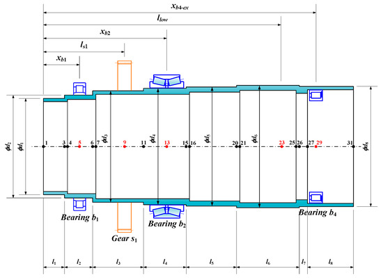
Figure 3.
Schematic diagram of node numbering and subcomponent positions of the outer rotor shaft.
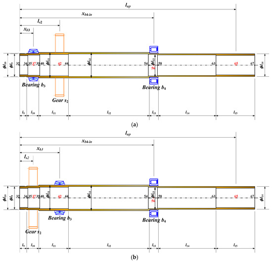
Figure 4.
Schematic diagram of node numbering and subcomponent positions of the inner rotor shaft. (a) Simple supported internal rotor shaft configuration. (b) Cantilever-supported internal rotor shaft configuration.
3.2. Stiffness Model of a Two-Branch Gear Parallel Transmission Configuration
The final stage transmission of the helicopter main reduction gearbox often adopts a parallel gear pair or planetary gear due to issues such as large structural dimensions and insufficient load capacity when using a single gear pair. Figure 5 illustrates a two-branch gear parallel transmission configuration. Since the left and right branch gear pairs often have a phase difference, the meshing process is not synchronous. Therefore, it is necessary to conduct a meshing phase analysis for the parallel gear pairs. Figure 6 provides a schematic diagram of the meshing phase of the inner rotor shaft parallel stage system, where the rotation direction of the gear s1 is counterclockwise.
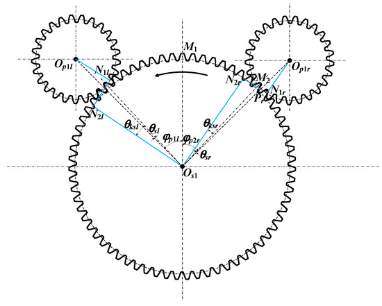
Figure 5.
Schematic diagram of the meshing phase of the outer rotor shaft and gear stage system.
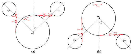
Figure 6.
Meshing schematic diagram of two-branch gear pair. (a) Outer rotor shaft gear pair. (b) Inner rotor shaft gear pair.
We assume that the gear centers of the gear s1, pinion p1l, and pinion p1r are located at Os1, Op1l, and Op1r, respectively. The angle between Os1, Op1l, and Op1r is considered, and the midpoint of the tooth tip of an arbitrary tooth on the inner gear s1 is denoted as M1. A line is drawn from Os1 to M1, and the view is rotated until the line Os1M1 is parallel to the y-axis. Further assume that the midpoint of the tooth tip of the gear tooth closest to and to the left of the line Os1 Op1r in gear s1 is M2. The number of teeth between M1 and M2 can be calculated using Equation (1). Subsequently, the meshing phase angle θsr can be solved using Equation (2).
where floor denotes the function which returns the greatest integer less than or equal to a given value.
N2r represents the theoretical terminal meshing point of the right branch gear pair, and Pr denotes the pitch point. Thus, θksr can be expressed as
where rbs1 represents the base circle radius of the gear, while N2rPr denotes half of the theoretical meshing line distance, which can be determined using Equation (5).
where rs1 represents the pitch circle radius of the gear.
Similarly, the meshing angle θksl of the left branch gear pair can be determined. Consequently, the meshing phase difference φp2lr between the left and right branch gear pairs can be expressed as
where mod represents the modulo function.
Furthermore, the meshing phase difference of the two branch gear pairs in the outer rotor shaft can be obtained. The detailed derivation process is omitted here for brevity.
If the gear is considered as a rigid body structure, its degrees of freedom can be written as
Figure 7 shows the schematic diagram of the relative displacement of the two-branch gear pair. From this, the relative displacement along the meshing line direction for the inner and outer rotor shaft gear pairs can be obtained, as shown in Equation (8).
where Ψsipij is the angle between the positive direction of the meshing line and the x-axis, which can be obtained from Equation (10). β is the helix angle of the gear. Since the gears used in this paper are straight gears, β is taken as 0. esipij represents the comprehensive transmission error of the gear, which can be expressed by Equation (10).
where αp is the meshing angle of the gear, and φ is the position angle of the branch gear.
where Es is the error amplitude, ωsp is the meshing frequency of the gear pair, and φs is the initial phase of the error, which is assumed to be 0 in this paper.
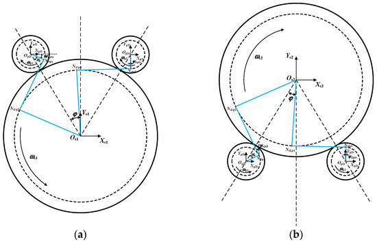
Figure 7.
Schematic diagram of the relative displacement of the two-branch gear pair. (a) Outer rotor shaft gear pair. (b) Inner rotor shaft gear pair.
The stiffness of the gear pair can be solved using the potential energy method, as detailed in reference [27,28,29], which will not be elaborated further here. To obtain the meshing stiffness model of the gear pair, the Lagrange equation can be used. Taking the left branch gear pair of the outer rotor shaft as an example, the elastic potential energy generated by the gear meshing is given by
Based on the Lagrange equation, the partial derivative can be obtained.
Therefore, the meshing stiffness matrix of the left branch gear pair of the outer rotor shaft can be shown as
where Ks1p1l represents the internal excitation vector of the gear. The meshing stiffness matrices for the remaining gear pairs can be obtained using the same method, which will not be described in detail in this paper. Table 4 provides the structural parameters of the gears.
Table 4.
Structural parameters of the rotor shaft gears.
3.3. Stiffness Matrix Assemble
Through the modeling and analysis of the rotor shaft and parallel gear pair, the stiffness matrix for each substructure can be obtained. The next step involves assembling the stiffness matrices of all substructures to form the overall stiffness matrix of the static model for the coaxial counter-rotating dual-rotor shaft system.
The assembly process for the stiffness matrix entails superimposing the stiffness matrix of each substructure onto the corresponding positions within the overall stiffness matrix. The specific steps are as follows: (1) establish the correspondence between the degrees of freedom (DOF) of each substructure and the global DOF; (2) place the elements of each substructure’s stiffness matrix into their respective positions in the overall stiffness matrix. Upon completion of these steps, with all substructure elements assembled according to these rules, the overall stiffness matrix for the static model is obtained.
Figure 8 illustrates the static model of the CRDRS system with simply supported bearings. The assembly process begins by integrating the outer rotor shaft unit, inner rotor shaft unit, gear meshing unit, and bearing support unit. Following this, the coupling relationships between substructures are established. Gear nodes 68 and 69 are connected to shaft system nodes 9 and 42 via splines, respectively. The inner and outer rotor shafts are coupled through the bearing support stiffness of the intermediate bearing, with connecting nodes 29 and 56. Rotor loads are applied at nodes 23 and 65, as detailed in Table 5. An input torque of 16,292 Nm is applied to nodes 70 through 73. The static model for the cantilevered support can be constructed in a similar manner. Once the model is constructed, the static equations for the coaxial counter-rotating dual-rotor shaft system can be derived, as shown in Equation (15). A diagram of the matrix assembly is provided in Figure 9.
where Ks, Kb, Kg and Ksc represent the stiffness matrices of the rotor shaft, support bearings, gears, and splines, respectively. qt is the displacement vector of each node in the static system. Ft is the rotor excitation vector.
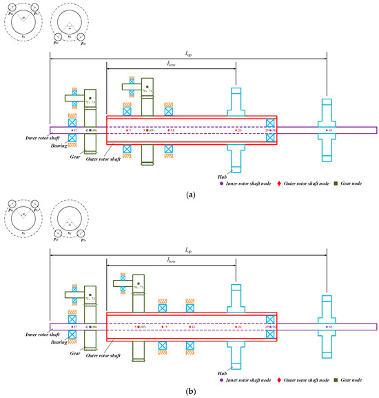
Figure 8.
Static model of the CRDRS system. (a) Simple supported internal rotor shaft configuration. (b) Cantilever-supported internal rotor shaft configuration.
Table 5.
Rotor load.
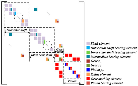
Figure 9.
Schematic diagram of the static matrix assembly for the CRDRS system.
In the static model, the coupling relationships between nodes are intricate, involving various coupling forms such as spline connections and intermediate bearing connections. To illustrate the coupling process between nodes, the outer rotor shaft gear and its corresponding shaft system node are shown as an example. The displacement vector of the outer rotor shaft gear is denoted as qg, and the corresponding rotor shaft system node is denoted as qs. These two nodes are connected through a spline coupling, and the corresponding elastic strain energy can be expressed as:
By taking the partial derivative of the elastic strain energy, the following equation can be obtained.
where kij represents the spline stiffness which can be derived from reference [30]. T is the transformation matrix, as given in Equation (18).
where the blank elements in the matrix are all 0.
Then, the coupling stiffness Kgs between qg and qs with the corresponding shaft system nodes can be expressed as
The coupling stiffness matrices between other nodes can be obtained using the same method.
3.4. Solution of Static Model
Assume that the spline connecting the outer rotor shaft and the outer rotor shaft gear is denoted as sp1, and the spline connecting the inner rotor shaft and the inner rotor shaft gear is denoted as sp2. Table 6 provides the spline structural parameters.
Table 6.
Spline structural parameters.
The coupling relationship between bearing support stiffness and the corresponding rotor shaft node displacement vector implies that the bearing stiffness can be calculated from the rotor shaft node displacement vector. By substituting the calculated bearing stiffness into the static model, the updated rotor shaft node displacement vector can be obtained. This results in an iterative relationship between the two structures. The same iterative process applies to the spline stiffness.
To solve the static equations, the relaxation iterative method is employed in this study. The relaxation method introduces a relaxation factor ω to adjust the iteration step size, which enhances convergence compared to standard iterative methods. Since the computational efficiency of the bearing support stiffness model and spline contact stiffness model differs, a two-layer iterative algorithm is applied. The iteration flowchart is shown in Figure 10. The iterative process is as follows:
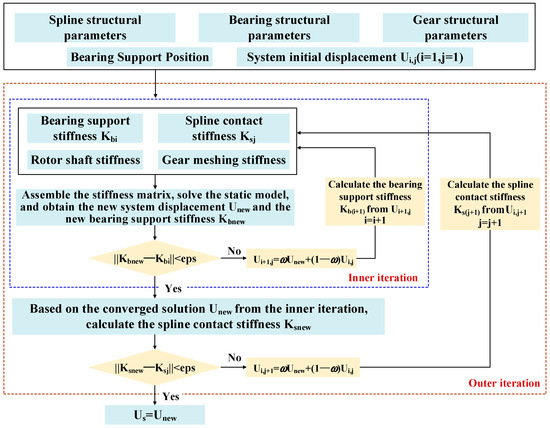
Figure 10.
Flowchart of the relaxation iterative method for solution.
- Initialization: Randomly assign a set of system initial displacements Ui (i = 1), ensuring that the values are not all zero. Define the structural parameters of components such as the rotor shaft, bearings, and gears.
- Bearing and Spline Stiffness Calculation: Based on the system displacement Ui, use the rolling bearing support stiffness model and the spline stiffness model to compute the bearing support stiffness Kbi and spline stiffness Ksj.
- Inner Iteration: Begin the inner iteration. Assemble the stiffness matrix according to the method in Section 3.2 Use Gaussian elimination to solve Equation (15) and obtain the new system displacement Unew.
- Convergence Check for Inner Iteration: Based on the new system displacement, calculate the updated bearing support stiffness Kbnew, and check whether the norm of Kbnew and Kbi is smaller than the allowable error eps. If the condition is not met, update the system displacement as follows:
- Ui+1 = ωUnew + (1 − ω)Ui, i = i + 1, and return to step 2 for a new iteration. If the condition is met, the inner iteration is considered to have converged, and the solution Unew is accepted. Proceed to step 5. Where ω represents the iterative relaxation factor. After extensive tuning, its value was set to 0.5. This specific value ensures algorithm convergence while maintaining high computational efficiency.
- 5.
- Outer Iteration: Begin the outer iteration. Based on the converged inner solution Unew, compute the new spline stiffness Ksnew, and check whether the norm of Ksnew and Ksj is smaller than the allowable error eps which is set to 0.5. If the condition is not met, increment j = j + 1, Ksj = Ksnew, and return to step 2. If the condition is met, it indicates that both the spline stiffness and bearing support stiffness have converged, marking the end of the outer iteration. The final converged solution Unew is output.
Through the iterative process described above, the number of calculations for spline contact stiffness is minimized, which significantly improves computational efficiency. The results indicate that the time required to calculate a set of system displacement vectors using a single-layer iteration is 383 s, while the time required using the two-layer iteration is 139 s. This shows an improvement in computational efficiency of 175.5%.
4. Effect of Bearing Support Parameters on the Static Characteristics of CRDRS System
The bearing support parameters include the support positions and bearing stiffness. The support position affects the bending stiffness of the rotor shaft, while the bearing stiffness influences the deformation at the support position. Both factors can impact the static characteristics of the rotor shaft. Therefore, it is necessary to explore the effects of bearing support position and bearing stiffness on the static characteristics of CRDRS system.
From Figure 3 and Figure 4, the positions of bearings b1~b4 are marked, corresponding to xb1, xb2, xb3 and xb4−ex (or xb4−in). The relationship between xb4−ex and xb4−in is as follows:
Due to support configuration and spatial constraints, the support positions need to be adjusted within a given range. To investigate the impact of bearing support positions on the static characteristics of the rotor shaft gear, it is necessary to ensure that the displacement of each bearing position is equal. Therefore, the movement range of the bearing positions is set as ±0.03 m. Table 7 provides the initial bearing support positions and the floating intervals for the simply supported configuration.
Table 7.
Initial bearing support positions and floating ranges under simply supported configuration.
Under cantilever support, the initial bearing support position and floating range of bearing b3 will change, while the positions of the other bearings remain unchanged, as shown in Table 8.
Table 8.
Initial bearing support positions and floating ranges under cantilever-supported configuration.
Based on the structural parameters and model of the rotor shaft, as well as the bearing usage in patents, the bearing model and structural parameters for the rotor shaft in this paper are determined, as shown in Table 9.
Table 9.
Rotor shaft bearing model and structural parameters.
4.1. Effect of Bearing Support Positions on the Static Characteristics of CRDRS System
Due to the meshing position between the rotor shaft gear and the left and right branch gears, the meshing stiffness may be affected, which could further influence the radial and angular deformations of the rotor shaft gear. Therefore, in this paper, it is assumed that the bearing support positions and stiffness of each rotor shaft bearing are constant, and the meshing angle of the gear is varied to study the impact of meshing stiffness on the radial displacement ws1 of rotor shaft gear s1, as shown in Figure 11. It can be observed that when a simply supported bearing structure is used, within one meshing cycle, after the gear undergoes alternating single and double tooth meshing, ws1 remains almost unchanged. The remaining static characteristic parameters exhibit the same trend, which will not be shown here. Therefore, in subsequent studies, the effect of gear meshing stiffness on the static characteristics of the dual rotor shaft system can be neglected. The same applies to the cantilever support.
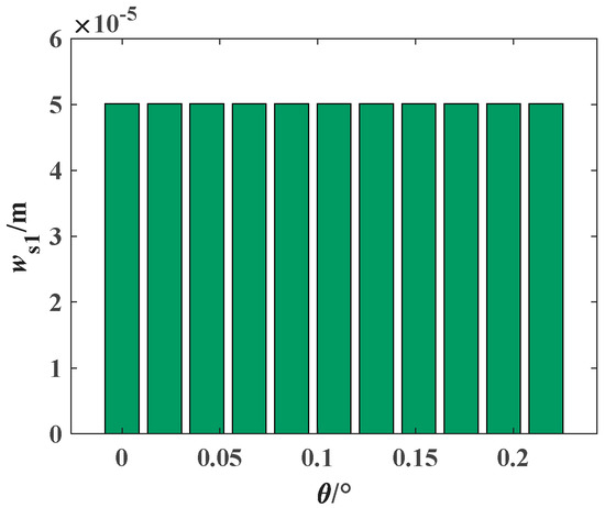
Figure 11.
Effect of rotational angle θ on the radial displacement ws1 of gear s1 under simply supported configuration.
Additionally, based on the static model of the coaxial counter-rotating dual rotor shaft system, we analyze the impact of bearing support positions on the static characteristics of the dual rotor shaft gears for both simply supported bearing configuration and cantilever bearing configuration.
- (1)
- Effect of bearing support positions on the static characteristics of CRDRS System under simply supported configuration
Under the simply supported bearing configuration, the initial positions and floating ranges of the rotor shaft bearings are shown in Table 7. By taking the upper and lower limits of the bearing support position floating ranges as boundaries, the range is divided into 11 equal segments. Each bearing position is labeled from p1 to p11, in increasing order. The influence of bearing support positions on the radial deformations ws1, ws2 and angular deformations θs1, θs2 of the dual rotor shaft gears is shown in Figure 12 and Figure 13. It can be seen that the radial and angular deformations of the outer rotor shaft gear are smaller than those of the inner rotor shaft gear. This is because the outer rotor shaft gear has a smaller distance to the bearings and, in comparison, the outer rotor shaft is shorter and thicker, resulting in higher structural stiffness and less susceptibility to deformation. The radial and angular deformations of the rotor shaft gears generally show a monotonically linear variation with respect to the bearing support positions. The deformation quantities Δw and Δθ are used to reflect the degree of influence of bearing support positions on the deformation of the rotor shaft gears, as marked in Figure 12a and Figure 13a. When Δw and Δθ are positive, it indicates a positive correlation; when Δw and Δθ are negative, it indicates a negative correlation.
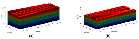
Figure 12.
Effect of bearing support positions on the radial deformation of rotor shaft gears under simply supported configuration. (a) ws1. (b) ws2.
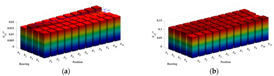
Figure 13.
Effect of bearing support positions on the angular deformation of rotor shaft gears under simply supported configuration. (a) θs1. (b) θs2.
From Figure 12a, it can be observed that the radial deformation of the inner rotor shaft gear s2 is more susceptible to the influence of bearing support positions. Bearing b3 has the greatest impact on ws2, and the two are negatively correlated. The impact of the remaining bearings on ws2 is ranked in descending order as follows: bearing b4, b2, and b1, which is inversely proportional to the distance between the bearing and gear s2. The radial deformation of gear s1 is much smaller than that of s2, so the impact of bearing support positions on ws1 is not significant, with bearing b1 having the greatest effect. Overall, the focus should be on reducing the radial deformation of gear s2, while considering the impact of bearing support positions on ws1 to a lesser extent.
In Figure 13b, it can be seen that the adjustment of bearing support positions has a certain impact on both θs1 and θs2, with bearings b1 and b2 having the greatest impact on θs1, and bearings b3 and b4 having the greatest impact on θs2. Combined with Figure 14, it is observed that when bearings b1 and b2 are farther from gear s1, θs1 decreases, and the influence of bearings b3 and b4 on θs1 is relatively small. In Figure 14b, when bearings b3 and b4 are closer to gear s2, θs2 decreases. This difference is caused by the differing support structures between the outer and inner rotor shafts.
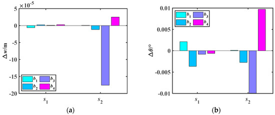
Figure 14.
Deformation quantities Δw and Δθ of rotor shaft gears caused by bearing support position displacements under simply supported configuration. (a) Δw. (b) Δθ.
- (2)
- Effect of bearing support positions on the static characteristics of CRDRS system under cantilever-supported configuration
Under the cantilever support configuration, the initial positions and floating ranges of the rotor shaft bearings are shown in Table 8. Compared to the simply supported configuration, the radial and angular deformations of the inner rotor shaft gear are smaller. This is because under the cantilever support, the inner rotor shaft gear position is almost free from bending moments, whereas under the simply supported configuration, the inner rotor shaft gear is subjected to a certain bending moment, and the magnitude of the bending moment is proportional to the distance from the bearing position.
From Figure 15, Figure 16 and Figure 17, it can be observed that under the cantilever support, the influence of bearing b3 on ws2 and θs2 changes from a negative correlation to a positive correlation. However, the deformation quantities Δws2 and Δθs2 decreased, indicating that compared to the simply supported configuration, the cantilever support weakens the influence of bearing b3 on gear s2. The influence of the remaining bearings on the gear deformations remains the same as in the simply supported case.
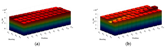
Figure 15.
Effect of bearing support positions on the radial deformation of rotor shaft gears under cantilever-supported configuration. (a) ws1. (b) ws2.
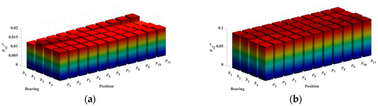
Figure 16.
Effect of bearing support positions on the angular deformation of rotor shaft gears under cantilever-supported configuration. (a) θs1. (b) θs2.
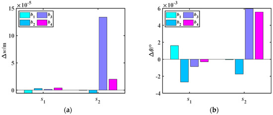
Figure 17.
Deformation quantities Δw and Δθ of rotor shaft gears caused by bearing support position displacements under cantilever-supported configuration. (a) Δw. (b) Δθ.
4.2. Effect of Bearing Support Stiffness on the Static Characteristics of CRDRS System
Based on the static mechanics model of the CRDRS system, the influence of bearing support stiffness on the static characteristics of dual rotor shaft gears is analyzed for both simply supported and cantilever-supported configurations. There are two methods for adjusting bearing support stiffness. One method is to set the bearing support stiffness and allow it to fluctuate within a certain range, thus exploring the impact of stiffness changes on the system’s static characteristics. The other method is to indirectly adjust the bearing stiffness by changing the structural parameters of the bearing (such as roller diameter, length, and bearing clearance) to conduct further analysis. The first method can intuitively reveal the relationship between bearing stiffness and the static characteristics of the system but has the following limitations: (1) Bearing stiffness changes dynamically with varying operating conditions, and this method cannot effectively account for real-time variations in bearing stiffness. (2) There is a coupling relationship between the various stiffnesses of the bearing (such as diagonal stiffness, cross-coupling stiffness), making it difficult for the first method to fully consider the interactions between stiffnesses. In contrast, the second method overcomes these issues. Therefore, this paper adopts the second method to analyze the influence of bearing support stiffness on the static characteristics of the dual rotor shaft system. Based on bearing stiffness theory, it can be observed that bearing stiffness is approximately linearly proportional to the roller length. Thus, in this section, bearing stiffness is indirectly changed by adjusting the roller length. For convenience, the roller length variation ratio is defined as α.
where le represents the original length of the bearing roller, and Δle is the variation range of the roller length, with the maximum value being 20% of le. Therefore, the value range of α is [0.8, 1.2].
- (1)
- Effect of bearing support stiffness on the static characteristics of CRDRS System under simply supported configuration
Figure 18 shows the influence of the roller length variation ratio α on bearing support stiffness under the simply supported configuration. Due to the coupling relationship between the primary stiffness and cross-coupling stiffness of the bearings, the changes in stiffness exhibit consistency. Therefore, the primary stiffness kxx is chosen to approximately represent the overall stiffness of the bearing, and the vertical axis kb in Figure 18 corresponds to the primary stiffness kxx of the respective bearing.
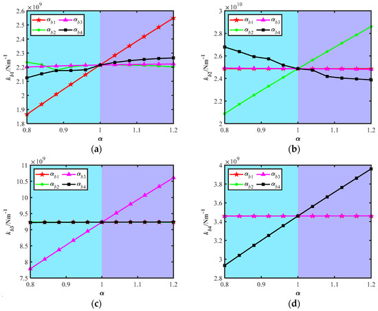
Figure 18.
Effect of roller length variation ratio α on bearing support stiffness under simply supported configuration. (a) kb1. (b) kb2. (c) kb3. (d) kb4.
It can be observed that the bearing support stiffness is influenced not only by its own roller length but also by the roller lengths of the other bearings. The degree of influence is related to the bearing position and the load applied. The bearing support stiffness increases monotonically with the corresponding roller length, indicating that adjusting the roller length to influence the support stiffness is feasible. The stiffness of the outer rotor shaft bearing is more easily affected by adjacent bearings and intermediate bearings, as it changes the contact state of the loaded rollers and the number of loaded rollers, leading to uneven stiffness variation. In contrast, the inner rotor shaft bearing, which is farther from the intermediate bearings, is less affected by the intermediate and outer rotor shaft bearings. The intermediate bearing, which shares a larger portion of the load, is influenced to a lesser extent by the other bearings.
After obtaining the influence of the roller length variation ratio α on bearing support stiffness, the next step is to analyze the impact of α on the radial and angular deformations of the rotor shaft gears, as shown in Figure 19 and Figure 20. The radial and angular deformations of the rotor shaft gears generally show a monotonic linear relationship with the bearing support stiffness. Therefore, the deformation quantities Δw and Δθ can also be used to reflect the degree of influence of bearing support stiffness on the deformation of the rotor shaft gears, as shown in Figure 21.
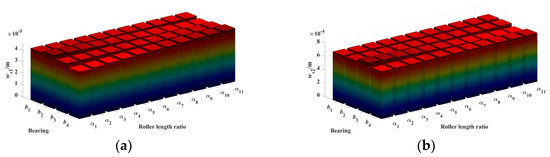
Figure 19.
Effect of roller length variation ratio α on the radial deformation of rotor shaft gears under simply supported configuration. (a) ws1. (b) ws2.
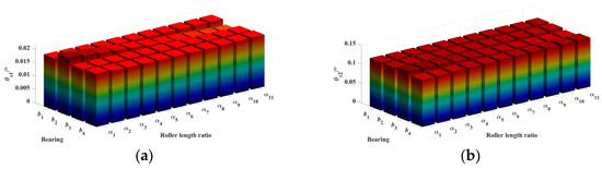
Figure 20.
Effect of roller length variation ratio α on the angular deformation of rotor shaft gears under simply supported configuration. (a) θs1. (b) θs2.
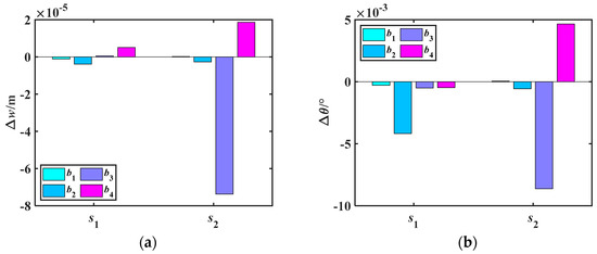
Figure 21.
Deformation quantities Δw and Δθ of rotor shaft gears caused by roller length variation ratio α under simply supported configuration. (a) Δw. (b) Δθ.
Comparing Figure 21 with Figure 14, the influence of bearing support stiffness adjustment on the deformation of the rotor shaft gears is weaker than that of bearing position changes. Bearing b3 has the greatest impact on ws2, and the relationship between them is negative. The next most influential bearing is the intermediate bearing b4. Adjusting the support stiffness of the remaining bearings has a relatively minor impact on improving the gear’s radial deformation. For angular deformation, bearing b2 has the greatest influence on θs1, far exceeding the effect of other bearings. The influences of bearings b3 and b4 on θs2 are also significant. By making targeted adjustments to the stiffness of bearings b2, b3 and b4, the deformation of the gears can be significantly improved.
- (2)
- Effect of bearing support stiffness on the static characteristics of CRDRS system under cantilever-supported configuration
Figure 22 shows the effect of the roller length variation ratio α on bearing support stiffness under cantilever support. Generally, the impact of α on bearing support stiffness under cantilever support is similar to that under simply supported support; however, there are the following differences: (1) For bearing b2, as α increases, the contact state of the bearing rollers changes. This is reflected by the bearing stiffness showing a linear increase followed by a brief inflection point, after which it resumes linear variation. (2) The stiffness of the external rotor shaft support bearings is more significantly affected by the adjacent bearings and the intermediate bearings. The number and location of the inflection points differ from those under simply supported support.
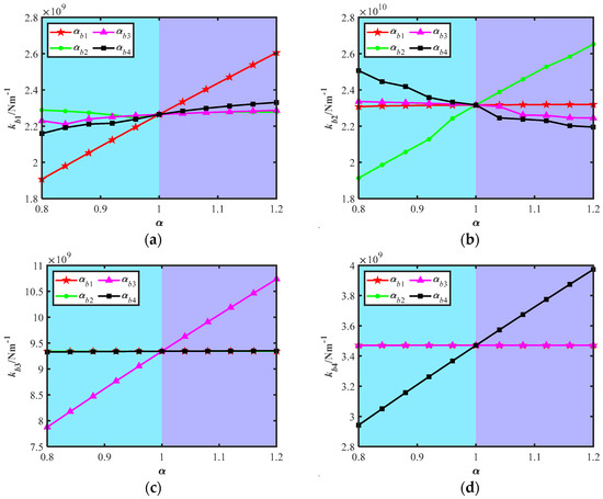
Figure 22.
Effect of roller length variation ratio α on bearing support stiffness under cantilever-supported configuration. (a) kb1. (b) kb2. (c) kb3. (d) kb4.
Subsequently, the effect of α on the radial and angular deformations of the rotor shaft gears is analyzed, as shown in Figure 23, Figure 24 and Figure 25. Under cantilever support, the relationship between α and the changes in Δw and Δθ follows the same pattern as under simply supported support. Specifically, α is correlated with the variations in radial and angular deformations. However, the extent of the influence is different. Overall, under cantilever support, the effect of α on the radial and angular deformations of the rotor shaft gears is smaller compared to that under simply supported support.
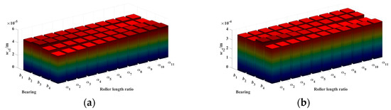
Figure 23.
Effect of roller length variation ratio α on the radial deformation of rotor shaft gears under cantilever-supported configuration. (a) ws1. (b) ws2.
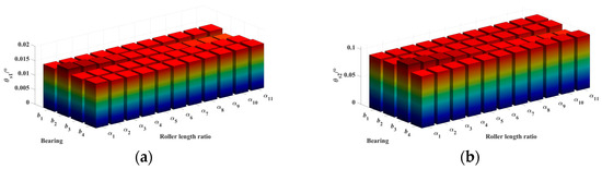
Figure 24.
Effect of roller length variation ratio α on the angular deformation of rotor shaft gears under cantilever-supported configuration. (a) θs1. (b) θs2.
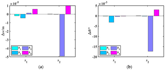
Figure 25.
Deformation quantities Δw and Δθ of rotor shaft gears caused by roller length variation ratio α under cantilever-supported configuration. (a) Δw. (b) Δθ.
5. Conclusions
In this paper, a static model of a coaxial contra-rotating dual-rotor shaft system is established, and the relaxation iteration method is employed for a two-level iterative solution. The effects of bearing support position and support stiffness on the radial and angular deformations of rotor shaft gears under simply supported and cantilever-supported inner rotor shafts are analyzed. The main conclusions are as follows:
- Regardless of whether the support is simply supported or cantilevered, the deformation (both radial and angular) of gear s1 is smaller than that of gear s2. Under the simply supported configuration, gear s2 experiences greater deformation due to bending moments, whereas under the cantilevered configuration, gear s2 is almost unaffected by bending moments, resulting in smaller deformation. Under cantilever support, the influence of bearing b3 on s2 changes from a negative to a positive correlation, and the deformation magnitude decreases.
- The radial and angular deformations of the rotor shaft gears exhibit a monotonic linear relationship with changes in the bearing support position. The deformation of gear s2 is more sensitive to the bearing support position, with bearing b3 having the greatest impact, showing a negative correlation. In contrast, gear s1 undergoes smaller deformation and is less sensitive to changes in bearing support position, with bearing b1 having the most significant effect.
- The effect of bearing support stiffness on gear deformation is smaller than that of support position but still follows a monotonic linear relationship. Bearing b3 has the greatest influence on the radial deformation of gear s2, while bearing b2 has the most significant impact on the angular deformation of gear s1. Adjusting the stiffness of bearings b2, b3, and b4 can effectively improve the deformation behavior of the rotor shaft gears.
The research findings of this study can guide the bearing support structure design of CRDRS system, improving the mechanical performance and reliability of the rotor shaft system. Furthermore, the static iterative solution method proposed in this paper provides a new approach for the static analysis of transmission systems.
Author Contributions
Conceptualization, X.Y.; methodology, W.C.; formal analysis, X.Y.; investigation, X.C.; writing—original draft preparation, X.C.; writing—review and editing, X.Y.; supervision, X.Y.; project administration, R.Z. All authors have read and agreed to the published version of the manuscript.
Funding
This work is supported by the National Natural Science Foundation of China (Grant No. 52275061).
Data Availability Statement
The datasets generated during and/or analyzed during the current study are available from the corresponding author on reasonable request.
Conflicts of Interest
The authors declared no potential conflicts of interest with respect to the research, authorship, and/or publication of this paper.
Appendix A
Stiffness matrix of shaft element
where , , , , .
References
- Goncharov, V.; Filimonikhin, G.; Dumenko, K.; Lychuk, M. Studying the peculiarities of balancing of flexible double-support rotors by two passive automatic balancers placed near supports. East. Eur. J. Adv. Technol. 2016, 4, 4–9. [Google Scholar] [CrossRef][Green Version]
- Goncharov, V.; Nevdakha, A.; Nevdakha, Y.; Gutsul, V. Research of stability and transition processes of the flexible double-support rotor with auto-balancers near support. East. Eur. J. Adv. Technol. 2016, 6, 22–27. [Google Scholar] [CrossRef][Green Version]
- Kiciński, J.; Drozdowski, R.; Materny, P. The non-linear analysis of the effect of support construction properties on the dynamic properties of multi-support rotor systems. J. Sound Vib. 1997, 206, 523–539. [Google Scholar] [CrossRef]
- Xiao, S.; Wu, F.; Ma, Y.; Hong, J. Investigation on the Excitation Characteristics and Dynamic Response of the Multi-Support Flexible Rotor with Misalignment. In Turbo Expo: Power for Land, Sea, and Air; American Society of Mechanical Engineers: New York, NY, USA, 2017; Volume 50930, p. V07BT33A006. [Google Scholar]
- Mishra, C.; Kashyap, A.K.; Samantaray, A.K. On the Dynamic Response of Rigid Rotor Supported by Rolling-Element Bearing. In Machines, Mechanism and Robotics: Proceedings of iNaCoMM 2017; Springer: Singapore, 2019; pp. 649–658. [Google Scholar]
- Bai, C.; Xu, Q.; Wang, J. Effects of flexible support stiffness on the nonlinear dynamic characteristics and stability of a turbopump rotor system. Nonlinear Dyn. 2011, 64, 237–252. [Google Scholar] [CrossRef]
- Huang, G.; Wang, X.; Qin, X.; Zhu, L.; Yi, S. Experimental investigation of dynamic behavior of rotor system with a novel double layers flexible support tilting pad bearing. Adv. Mech. Eng. 2022, 14, 16878132221116482. [Google Scholar] [CrossRef]
- Wang, Y.X.; Yan, J.; Wang, S.Z. An Effective Method for Determining Finite Element Model Parameters of Rotor Elastic Support System. Appl. Mech. Mater. 2012, 141, 191–197. [Google Scholar] [CrossRef]
- Garfinkle, M. Coaxial Helicopter Rotor System and Transmission Therefor. US3669564A, 13 June 1972. [Google Scholar]
- Gmirya, Y. Rotor Apparatus. WO 2015/102634 Al, 9 July 2015. [Google Scholar]
- Yanagisawa, G. Coaxial Twin-Rotor Type Helicopter. USOO6293492B1, 25 September 2001. [Google Scholar]
- Herruzo, J.C. Rotor Blade Pitch Control for Helicopter with Coaxial Rotors. EP0038441A1, 28 October 1981. [Google Scholar]
- Sergeevich, P.S.; Petrovich, B.A.; Nikolaevich, S.S.; Mikhajlovich, T.A.; Aleksandrovich, C.J. Coaxial-Rotor Helicopter Gearbox. RU2541569C1, 8 August 2013. [Google Scholar]
- Czajkowski, Ł. Mechanical analysis process of a coaxial counter rotor for applications in unmanned ultra-light units. Trans. Aerosp. Res. 2019, 2019, 38–58. [Google Scholar] [CrossRef]
- Baskin, B.K.; Wedman, K.; Garcia, T.A.; Duello, C. Counter-Rotating Rotor System with Stationary Standpipe. US9623964B2, 18 April 2017. [Google Scholar]
- Baskin, B.K.; Garcia, T.A. Counter-Rotating Rotor System with Static Mast. US9725166B2, 8 August 2017. [Google Scholar]
- Mikheev, S.V.; Gubarev, B.A.; Vagis, V.P. Helicopter with Coaxial Main Rotors. RU2265554C1, 4 January 2004. [Google Scholar]
- Liang, H.; Shi, Q.; Hu, Q.; Liu, Z.; Wu, Z.; Yu, W. A Double-Engine Input Coaxial Double-Rotor Main Gearbox and aircraft. CN111301669A, 19 June 2020. (In Chinese). [Google Scholar]
- Weiner, S.D.; Eadie, W.J. Main Rotor Rotational Speed Control for Rotorcraft. US20170283047A1, 5 October 2017. [Google Scholar]
- Hong, J.; Song, Z.; Wang, D.; Ma, Y. Design method for bearing-support structure and mechanical properties of high-speed rotor system. J. Aerosp. Power 2019, 34, 961–970. [Google Scholar] [CrossRef]
- Yu, H.; Ma, Y.; Xiao, S.; Hong, J. Mechanical and dynamic characteristics of bearing with looseness on high-speed flexible rotor. J. Beijing Univ. Aeronaut. Astronaut. 2017, 43, 1677–1683. [Google Scholar]
- Xia, Y.; Wu, Y.; Zhang, W. Analysis on Vibration Response Characteristics of Steam Turbine Unit under Flexible Support. J. Eng. Therm. Energy Power 2021, 36, 157–164. [Google Scholar]
- Che, X.; Zhu, R. Study on the effect of bearing position and stiffness on the dynamic behavior of output stage of CHT system based on the cylindrical gear meshing. Proc. Inst. Mech. Eng. Part C J. Mech. Eng. Sci. 2024, 238, 9856–9877. [Google Scholar] [CrossRef]
- Zuo, G.; Hou, L.; Lin, R.; Ren, S.; Chen, Y. Combination resonance and primary resonance characteristics of a dual-rotor system under the condition of the synchronous impact of the inter-shaft bearing. Sci. Rep. 2023, 13, 1153. [Google Scholar] [CrossRef] [PubMed]
- Deng, S.-E.; Fu, J.-H.; Wang, Y.-S.; Yang, H.-S. Analysis on dynamic characteristics of aero-engine rolling bearing/dual-rotor system. J. Aerosp. Power 2013, 28, 195–204. [Google Scholar]
- Chen, S.; Tang, J.; Li, Y.; Hu, Z. Rotordynamics analysis of a double-helical gear transmission system. Meccanica 2016, 51, 251–268. [Google Scholar] [CrossRef]
- Che, X.; Zhu, R. Nonlinear dynamic analysis of helical gear-rotor-bearing coupled system based on bearing load calculation with TRB clearance. Nonlinear Dyn. 2023, 111, 17787–17807. [Google Scholar] [CrossRef]
- Song, J.; Hou, L.; Ma, R.; Li, Z.; Lin, R.; Chen, Y.; Chen, Y.; Saeed, N.A. Nonlinear Dynamic Modeling of a Gear-Bearing Transmission System Based on Dynamic Meshing Parameters. Machines 2025, 13, 230. [Google Scholar] [CrossRef]
- Kong, X.; Yuan, Y.; Sun, S.; Xin, Y.; Meng, Q. Time-Varying Meshing Stiffness Calculation and Dynamics Simulation of Multi-Spalling Gear. Machines 2025, 13, 299. [Google Scholar] [CrossRef]
- Yu, P.; Wang, C.; Liu, Y.; Chen, G. Analytical modeling of the lateral stiffness of a spline coupling considering teeth engagement and influence on rotor dynamics. Eur. J. Mech. A Solids 2022, 92, 104468. [Google Scholar] [CrossRef]


Disclaimer/Publisher’s Note: The statements, opinions and data contained in all publications are solely those of the individual author(s) and contributor(s) and not of MDPI and/or the editor(s). MDPI and/or the editor(s) disclaim responsibility for any injury to people or property resulting from any ideas, methods, instructions or products referred to in the content. |
© 2025 by the authors. Licensee MDPI, Basel, Switzerland. This article is an open access article distributed under the terms and conditions of the Creative Commons Attribution (CC BY) license (https://creativecommons.org/licenses/by/4.0/).