1. Introduction
Single-phase squirrel-cage induction motors (SPSCIM) are fundamental components in industrial and, primarily, domestic applications. However, as the demand for energy efficiency increases, it is essential to enhance their performance in terms of both operation and design. Two key research areas are optimal motor design and parameter determination, as these define the motor’s behavior and characteristic curves. One approach to evaluating the electromagnetic design characteristics of an electric motor is the finite element method (FEM), which allows for quantifying the magnetic field, electromagnetic losses, and torque under different load conditions, as seen in [
1]. Previous studies have demonstrated that unbalanced operation in a three-phase motor negatively impacts losses and efficiency, highlighting the need to investigate its effects on vibrations and structural forces. Additionally, winding optimization, along with parameter adjustments, is employed to maximize efficiency. Reference [
2] states that low-power single-phase squirrel-cage induction motors (SPSCIMs) in the 0.5–1.5 kW range account for approximately 10% of the total energy consumption of AC motors. Their study analyzes the impact of the main winding’s magnetic flux in the interpolar space and the resistive–inductive ratio. These investigations are valuable for proposing new designs, such as the one presented in [
3], which focuses on a 45 W SPSCIM for ceiling fans aimed at improving efficiency. The study employs finite element analysis (FEA) to achieve efficiency improvements of up to 57% or a power consumption of 35 W while maintaining the same fan dimensions—values comparable to those of BLDC fans. One strategy used in this type of study is the determination of equivalent circuit parameters based on various approaches that utilize catalog data to evaluate manufacturers’ design strategies. This allows for analyzing variations in winding resistance across different brands, such as LS, WEG, ABB, and SIEMENS, as observed in [
4]. The transition from IE2 to IE3 efficiency classes reflects specific manufacturer strategies to meet efficiency requirements, either by reducing series resistance or increasing parallel resistance.
To accurately estimate motor parameters, optimization techniques are employed, such as the approach used in [
5] for three-phase induction motors, which achieves a lower error margin (1–3%) compared to manufacturer estimates. This method first optimizes the stator parameters, followed by the rotor parameters, using the least squares method and manufacturer data, resulting in a more accurate model.
A similar study focuses on parameter estimation for NEMA A and B single-cage induction motors, utilizing manufacturer data and nonlinear equations dependent on slip, solved through a least squares-based algorithm [
6]. This method has been validated on more than 300 motors, consistently aligning with manufacturer specifications. Another strategy involves parameter estimation based on operational load data, with a focus on modeling and fault diagnosis in electrical systems [
7]. This study highlights the limitations of traditional IEEE techniques, which rely on offline testing and those experimental validations are sensitive to environmental conditions. Additionally, the research employs particle swarm optimization (PSO) and H-G diagrams as part of the study.
An alternative approach utilizes phase-to-phase variable-frequency testing under standstill conditions, where the response data is incorporated into an error function to estimate the parameters of single-cage and double-cage induction motors [
8]. The single-cage model fails to accurately fit frequencies above a few tenths of a Hertz, whereas the double-cage model achieves a good fit within the 0–150 Hz range. These models were validated by comparing them with two additional tests: a steady-state torque and current test at various speeds, and a dynamic free acceleration test. Another study proposes the use of a hybrid water cycle algorithm for parameter estimation, leveraging both literature-based and experimental data from a 4 kW three-phase motor for single-cage and double-cage models. The results demonstrate that the algorithm achieves higher accuracy than other well-known methods with fewer iterations. In [
9], a study based on particle swarm optimization (PSO) algorithms is presented, validated through experimental testing on a 3 kVA transformer and a 2 hp induction motor, resulting in a simple and efficient methodology. For more complex studies, a method based on artificial neural networks and adaptive neuro-fuzzy inference systems (ANFIS) is introduced, as seen in [
10], where single- and double-cage models are compared using experimental data from 20 motors of varying power ratings. The results demonstrate that both methods provide high accuracy, emphasizing the importance of advanced techniques in this field. Another study presents a comparative analysis using feedforward neural networks (ANFIS) and non-memorized Elman artificial neural networks (ANN) [
11,
12]. The authors provide an extended explanation of the application of neural networks for parameter estimation and conclude that while both methods are relevant, ANFIS outperforms ANN in parameter estimation when applied to manufacturer data from 20 motors at different power levels.
A significant number of studies focus on three-phase induction motors due to their widespread industrial application; however, the single-phase motor is also of great importance and should be considered. A simple approach is developed in calculations, as seen in [
13], where the conventional method is compared with the Suhr method and the two-phase method for the SPSCIM. The study validates the results through simulations employing the finite element method (FEM) and electrical machine design calculations, confirming adequate accuracy for the methodology. Finally, an alternative method is proposed to compensate for the bifacial supply, utilizing autotransformers and a variable capacitor. In [
14], a scheme is proposed to determine the stator parameters of the SPSCIM to generate circular rotating fields and maximize efficiency. The results showed that the rotating fields in the optimized models were more circular, significantly reducing the torque ripple by 85% and 81%, respectively. Additionally, the copper losses in the stator coil decreased to 174.54 W and 106.75 W, which improved efficiency by 0.57% and 1.16%. Finite element simulations corroborated the results through an appropriate distribution of main and auxiliary currents, improving overall efficiency.
Another study develops an aggregated model of the SPSCIM for residential heat pumps using classical testing and the IEEE 39-bus model to evaluate its behavior under three-phase faults of 15 and 90 cycles [
15]. The study focuses on the model, which is verified by comparing it with simulations of individual motors. Another study for SPSCIM uses the “double revolution” model of a 0.5 hp motor for magnetic circuit optimization through finite element simulations (FEA) to validate the results. The findings indicate that improving the slot air density and optimizing the geometry reduces copper losses, enhancing efficiency without increasing manufacturing costs [
16]. Despite the preference for single-phase induction motors in industrial and domestic applications, the optimization and behavior of these motors has been less extensively researched. The focus of this work is to integrate different methodologies related to parameter estimation and the evaluation of the characteristic performance curve of the Single-Phase Squirrel Cage Induction Motor (SPSCIM), highlighting its potential for future research in design optimization and control.
2. Materials and Methods
The methods used to obtain the parameters of the SPSCIM aim to determine the electrical and magnetic constants that characterize the behavior of the machine within a model or equivalent circuit. In this context, the presented work seeks to combine FEM simulations with experimental approaches to analyze the magnetic field distribution and performance of a single-phase induction motor, as well as the classical methods and the Suhr method for parameter estimation.
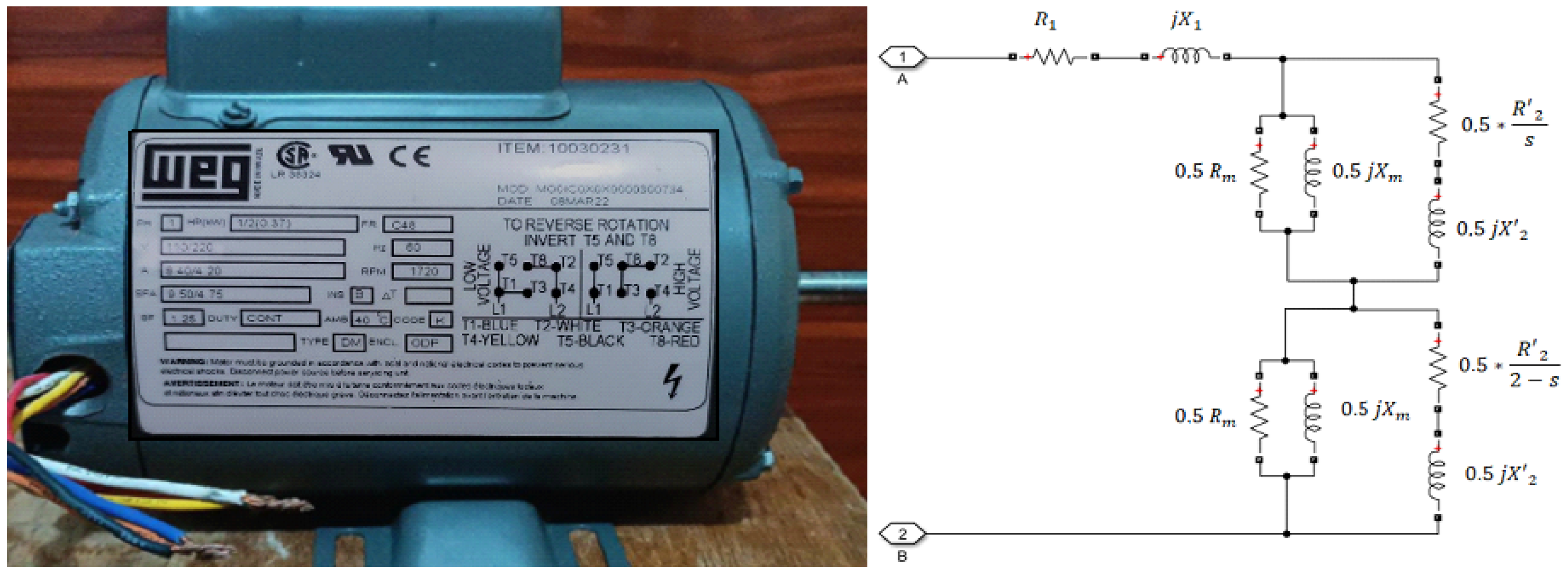
Experimental results are presented that validate the accuracy of the simulations and allow for a detailed comparison of the torque-speed curve obtained through load tests, which involved taking measurements in a test module with a load emulator. The machine used for determining the electrical parameters was a single-phase induction motor for continuous use of 373 W (0.5 hp) at 1720 RPM and four poles, rated for 110/220 V and 8.4/4.2 A from the WEG brand, illustrated in
Figure 1. Also, in
Figure 1, the simple cage model used for the calculations in the determination of the parameters can be observed. This model is based on the additional physical characteristics from the motor’s nameplate, such as the frame size FR of C48, insulation WS of class B, open enclosure with drip protection ODF, and an operating temperature of 40 °C. In the equivalent circuit of
Figure 1,
and
represent the stator resistance and leakage reactance, while
and
are the rotor resistance and leakage reactance referred to the stator side. The magnetizing branch, formed by
and
, models the core losses and the magnetizing current. The term
accounts for the slip-dependent rotor power conversion. This standard single-cage model captures the essential steady-state behavior of the motor. This nameplate information, along with experimental validation, was used for the development of finite element simulations to validate the design of the SPSCIM.
On the other hand, the classic equivalent circuit model shown in
Figure 1 enabled, through calculations and simulations, the description of the classical and Suhr methods for determining the motor parameters in the characteristics and real distribution of the windings. These methods are based on direct current (DC) tests, the locked-rotor test, and the open-circuit test.
2.1. Simulations Using the Magnetic Finite Element Method
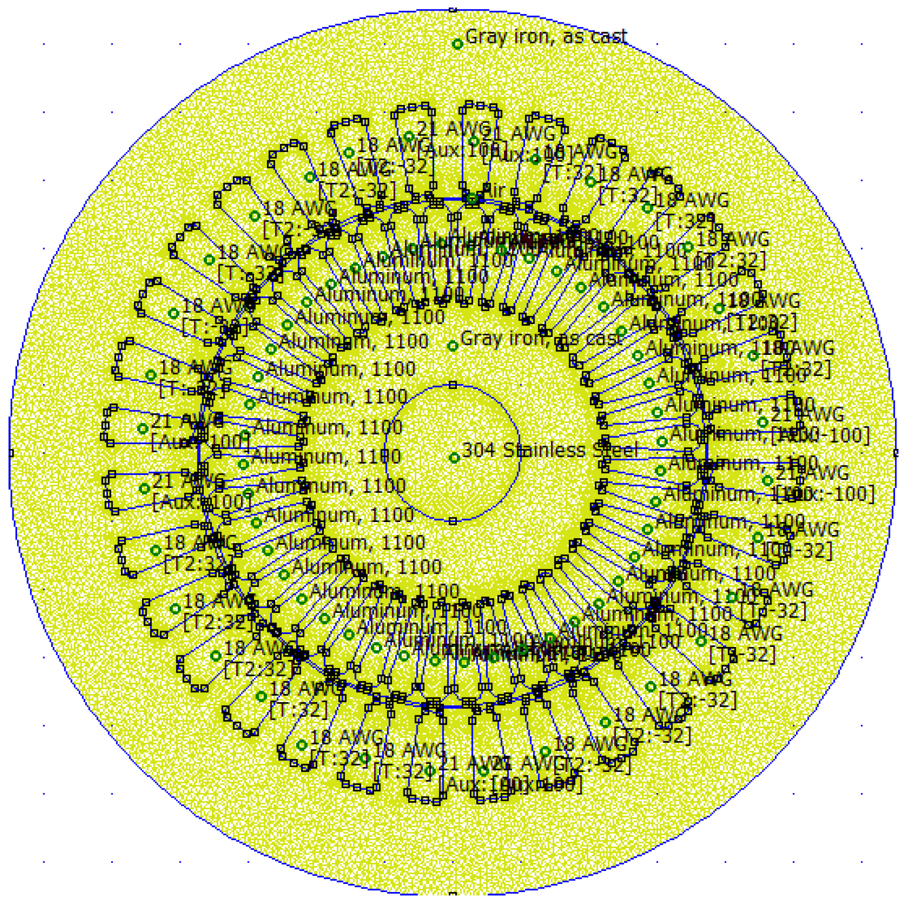
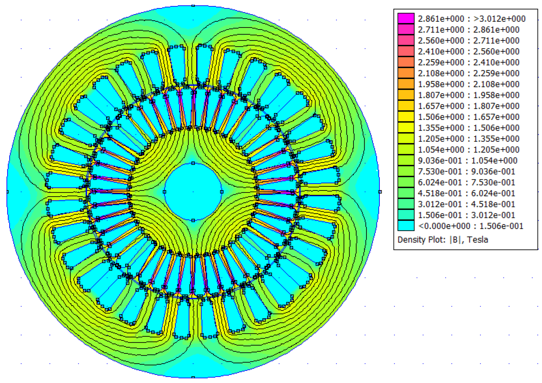
The Magnetic Finite Element Method (FEMM) software was used as a tool to analyze and visualize the magnetic field flux distribution of the SPSCIM. Detailed information was obtained regarding the flux linkage lines, trajectory, concentrations, and resulting magnitudes, considering the saturation effects from the core and winding construction details.
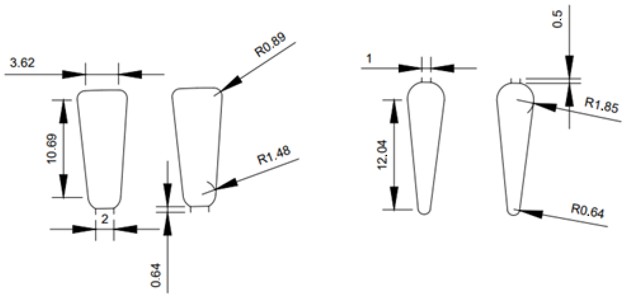
Figure 2 describes the dimensions of the stator grooves (right) and rotor grooves (left), which are repeated in a total of 32 slotes in the stator and 44 slotes in the rotor of the SPSCIM.
Additionally, it is necessary to identify the winding configuration encapsulated in the stator of the SPSCIM. This can be detailed through the horizontal winding diagram developed in
Figure 3 for the pole and terminal arrangement.
The winding is of a concentric type in groups of three coils per pole, which is very common among manufacturers. This structure results in two pole pairs for the 1720 RPM rated speed after considering the slip. Additionally, certain constructive data about the total winding denoted
, can be obtained, such as its distribution around the number of slots
of the stator for two magnetic poles
p:
The 2/3 of the total winding in Equation (
1) was used for the working winding
and the remaining 1/3 for the starting coil
following the standard construction practice for this type of motor. The angular pitch
a between the slots
is given by the Equation (
2) as:
The number of slots per phase for the working coil
, is calculated using a mathematical expression based on the described geometry with the Equation (
3) as follows:
Similarly, for the starting coil
of the SPSCIM, the Equation (
4), is used as:
To determine the total number of turns
of the working coil, Equation (
5) was used, which is a function of the slot length
, the slot diameter
, a current density factor
, the magnetic flux density
B and an industrial design constant
C. A value of 133 was considered for this study for a 60 Hz frequency of the grid, following standard practice for industrial machines operating.
For the number of turns in the auxiliary or starting winding
, a factor of 0.5 times
, was considered, since the latter is only used during the startup phase. This is a design parameter that allows the coil to withstand the startup currents while using fewer turns. Finally, the number of slots used in each winding is determined by dividing the number of turns by the number of slots
which allows the evaluation of the electromagnetic operating characteristics of the SPSCIM through finite element simulations to determine its parameters. It is important to note that all these characteristics were essential for the development of the finite element simulations. A crucial value is the magnetizing inductance
which is calculated through the total energy stored in the magnetic circuit
and the no-load current
as follows:
The magnetic stored energy from expression (
6) can be considered from the simulation. Another alternative is based on expression (
7), which involves the magnetic flux density
B present in a volume
v with magnetic permeability
e. For the SPSCIM, this
e represents the permeability of the core material along with other physical or standard characteristics of the motor.
A similar approach can be used to determine the other parameters of the SPSCIM, such as the resistance and reactance of the windings, based on the available simulation results. Another parameter is magnetizing resistance, which can be determined through the power present in the magnetic core.
2.2. Classic Metod
The classical method can be used for an induction motor, whether three-phase or single-phase, through standard tests that describe its electrical and mechanical behavior. The first test, performed with direct current (DC), allows the determination of the stator resistance
of the SPSCIM by applying a DC source
and measuring the current
. The skin effect and the characteristics of the iron are included with a compensation factor of 1.15, as follows in Equation (
8).
The second test is the locked-rotor or short-circuit test, which requires a variable alternating current (AC) voltage applied to the stator until full load is reached on the SPSCIM. In this test, the air gap resistance is very high, allowing the determination of
using
obtained from Equation (
1) and the voltage
, current
and power
measurements under locked rotor conditions. To calculate
, we use:
Equation (
9) is in an implicitly form through the total reactance
that can be calculated; its result allows the calculation of the equivalent impedance, and thus, the determination of the rotor and stator reactance through an estimated separation based on the recommendations for Class B motors with Equation (
10), as follows:
The no-load test of the SPSCIM facilitates the determination of rotational and magnetizing losses through the measurements of voltage
, current
and power
. This is because most of the consumption occurs in the magnetizing branch and in the rotational losses:
The Equation (
11) provides information to calculate the internal induced voltage of the SPSCIM as an intermediate step for calculating the magnetization parameters. This internal voltage can be determined as follows in the (
12) through parameters already calculated as:
The next step in this classical metodology is to calculate the resistance, or real part of the magnetizing losses using the internal voltage and the losses obtained from Equations (
11) and (
12), as follows:
Finally, Equation (
13) allows for the separation of the reactive part of the magnetization through Equation (
14):
2.3. Suhr Metod
The Suhr method, similar to the classical method, uses the DC, locked-rotor, and no-load tests, with the difference that it directly calculates the magnetic reactance
as follows:
From Equation (
15), we can deduce that
can be determined from the locked-rotor test of the classical method, and for
and
the no-load test is required with power measurements in the auxiliary and main windings, respectively, as detailed in the work [
13]. This characteristic makes the Suhr method suitable for the test station capacities. To determine
, the reactive power is also measured in the auxiliary winding during the no-load testis given by Equation (
16), in the function of the no load current
as follows:
And similarly, for , the calculation can be done with the power measurement in the main winding of the SPSCIM. A relevant detail of this method that must be remembered is that the method uses the same tests as used in the classical method that allows the reduction of number of meters to use.
3. Test Station Characteristics for the SPSCIM
To carry out this methodology regarding parameter calculation, computational tools and a test station focused on measuring experimental variables are required, such as voltage, current, power, and speed of the SPSCIM. The main components considered for the test station are detailed in
Table 1 to meet the needs of the experiment.
Figure 4 shows the test station, encapsulated in blocks and mounted on a control panel with terminal blocks connected to the SPSCIM and meters. The motor is coupled with a load emulator, which simulates different operating conditions. The station includes an Atmega2560 development board for data acquisition to a computer. Once the test station was configured according to the experimental requirements, the corresponding measurements were taken for the DC test, locked-rotor test, and open-circuit test, using the Classical and Suhr methods.
These tests were crucial for obtaining the electrical parameters of the SPSCIM equivalent circuit and also allowed progress toward load evaluation for the determination of characteristic curves. For this reason, a series of measurements were performed to calculate the average value to be used.
5. Load Test and Characteristic Curves Comparison
The load test for the SPSCIM is performed to determine the motor’s operability and efficiency when fed with a specific voltage at different load levels, allowing for a comparison with simulations of practical scenarios of the torque-speed characteristic curve. To do this, a universal machine was mechanically anchored to the shaft of the SPSCIM and operated in generator mode to emulate a controlled load. To obtain the characteristic curve data, different load levels were gradually applied, as shown in
Table 5.
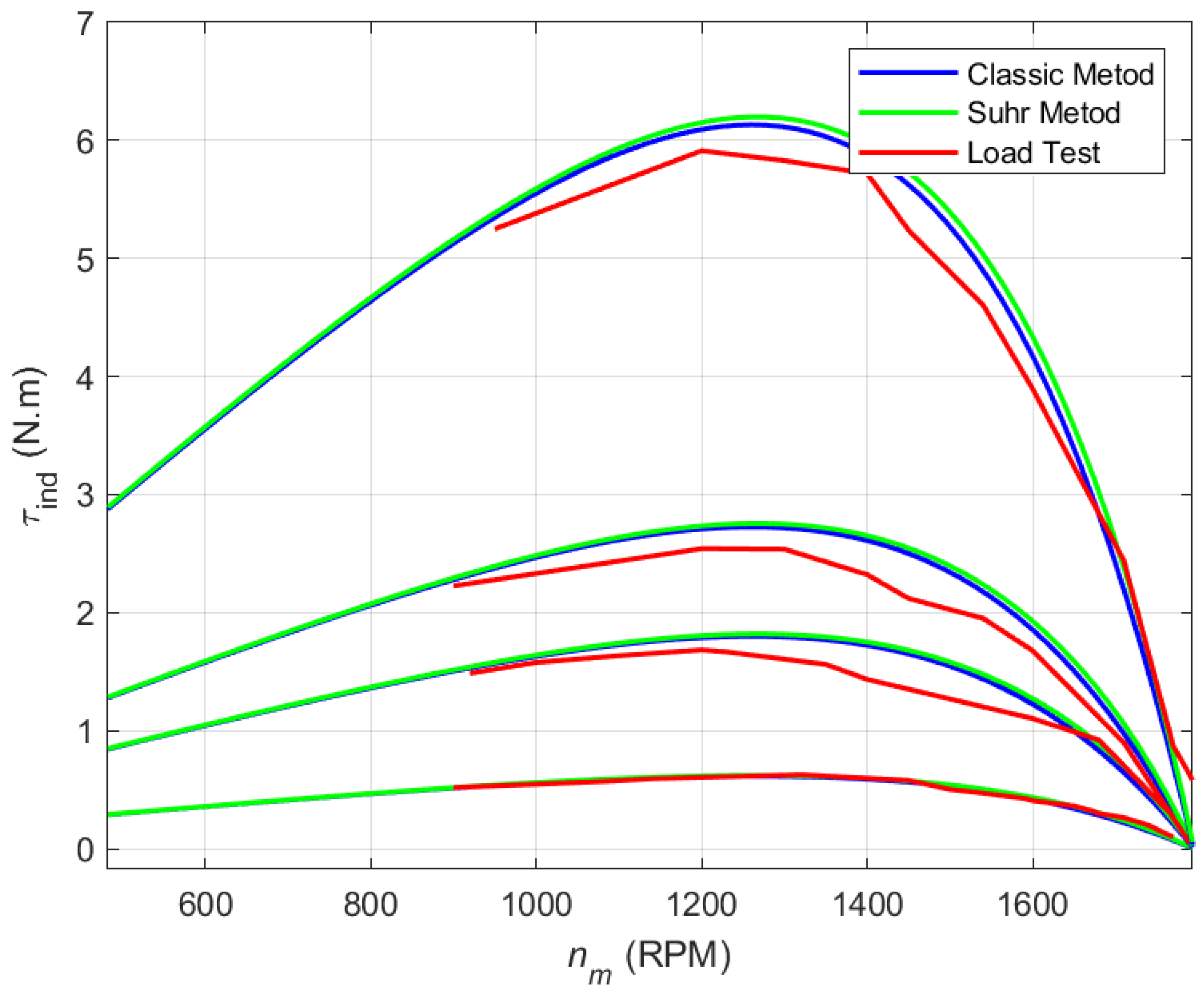
In this procedure, a manual brake, initially intended for the locked-rotor test, was used as a gradual alternative during the 80 V and 120 V tests at higher load levels. The purpose of this was to minimize the time the SPSCIM was subjected to significant disturbances and prevent damage from overheating. The torque-speed curves were generated using MATLAB software, as shown in
Figure 7, for the different test groups corresponding to the applied voltages.
As shown in
Figure 7, the curves obtained using the classical and Suhr methods are very similar for all selected voltage levels and throughout the entire load range. On the other hand, the experimental load curves differ from the characteristic curves of the classical and Suhr methods, but with a small error, which becomes more evident as higher load levels are applied in the different voltage curves. This is largely due to errors introduced by the meters during extended test durations at high loads, such as temperature conditions, friction, and variable mechanical losses. It should be noted that the motor operates normally in the linear region near the rated speed. However, the measured range for the characteristic curves at the different voltage levels largely corresponds to the expected behavior.
6. Conclusions
There are several methods for the analysis and determination of parameters, and since the focus of the study is the parameterization of a SPSCIM through its physical and experimental characteristics rather than the efficiency of the method, the classical method and Suhr method were chosen, based on standard tests such as the no-load, blocked rotor, and DC tests. Additionally, the MATLAB/Simulink simulation method is used for validation, along with finite element simulations to study the magnetic characteristics of the SPSCIM and as an alternative for estimating its parameters. The implementation of a test module was necessary for data acquisition, serving as a systematic record of information from the different tests for the SPSCIM parameters and the development of the final experiment based on multiple variable load tests. With the calculated parameters, the characteristic curves of the SPSCIM can be plotted for the proposed methods, with the additional detail of repeating the calculations for different voltage levels. This allowed for a comparison of the methods with the load test measurements, demonstrating the effectiveness of the experiment for determining the parameters of the studied SPSCIM and its magnetic analysis through the finite element method, based on its constructive characteristics and design criteria. A key innovation of this work lies in the integrated and comparative approach, combining classical estimation methods, FEM simulations, and dynamic MATLAB modeling to evaluate the torque-speed behavior of the SPSCIM under multiple voltage levels. A perspective rarely addressed in previous literature together, particularly for single-phase machines. Furthermore, most previous studies focus on three-phase induction motors, while this paper highlights the importance and characterization of single-phase motors, specifically SPSCIMs, as an extended basis for future work in the optimization of their design and control.


