Article

Non-Singular Fast Terminal Composite Sliding Mode Control of Marine Permanent Magnet Synchronous Propulsion Motors

Guangdong Provincial Key Laboratory of Intelligent Equipment for South China Sea Marine Ranching, Guangdong Ocean University, Zhanjiang 524088, China
*
Author to whom correspondence should be addressed.
Machines 2025, 13(6), 470; https://doi.org/10.3390/machines13060470
Submission received: 9 April 2025 / Revised: 19 May 2025 / Accepted: 26 May 2025 / Published: 29 May 2025
(This article belongs to the Section Automation and Control Systems)

Abstract

:
Regarding the high susceptibility problem of the Permanent Magnet Synchronous Motor (PMSM) to various uncertain factors, including load variations, parameter perturbations, and external interferences in the ship’s electric propulsion system, this paper presents a non-singular fast terminal composite sliding mode control (NFTCSMC) strategy based on the improved exponential reaching law. This strategy integrates the system’s state variables and the power function of the sliding mode surface into the traditional exponential reaching law, not only enhancing the sliding mode reaching rate but also effectively mitigating system chattering. Additionally, a sliding mode disturbance observer is developed to compensate for both internal and external disturbances in real time, further enhancing the system’s robustness. Finally, the proposed control strategy is experimentally validated using the rapid control prototyping (RCP) technology applied on a semi-physical experimental platform for ship electric propulsion. Experimental results indicate that, compared to traditional proportional–integral (PI), sliding mode control (SMC), and fast terminal sliding mode control (FTSMC) strategies, the NFTCSMC strategy enhances the propulsion and anti-interference capabilities of the propulsion motor, thereby improving the dynamic performance of the ship’s electric propulsion system.

1. Introduction

Permanent Magnet Synchronous Motors (PMSMs) with low speeds and high power density are the mainstream choice for propulsion motors in ship electric propulsion systems. However, due to the harsh operating conditions of ships, characterized by oscillations, nonlinearities, strong coupling, large inertia delays, and susceptibility to external disturbances such as wind, waves, and currents, traditional proportional–integral (PI) control leads to significant oscillations in motor speed and electromagnetic torque, along with poor resistance to load torque disturbances. These issues severely degrade the propulsion and control performance of PMSMs, making it difficult to achieve high efficiency, rapid response, and robust performance in ship electric propulsion systems [1].
To improve the dynamic response and robustness of ship electric propulsion systems under varying speed and load conditions, many modern control strategies have been proposed, such as fuzzy control [2,3,4], model predictive control [5,6,7,8,9], adaptive control [10,11,12], and sliding mode control (SMC) [13,14,15,16,17,18,19]. Among these, SMC stands out as a simple yet effective nonlinear control technique, known for its fast response and resilience to parameter fluctuations and disturbances, making it particularly effective for handling the variations typically in ship electric propulsion motors. Traditional SMC typically uses linear sliding mode hyperplanes, which leads to slow asymptotic convergence. In contrast, terminal SMC, which employs dynamic nonlinear sliding mode hyperplanes, enables faster convergence within a finite time frame [20,21,22]. However, as the system state approaches zero, the exponential term in the control law causes the control variable to increase uncontrollably toward infinity, resulting in a singularity.
To overcome this issue, a non-singular terminal SMC was introduced, wherein the switching function in the sliding mode hyperplane is modified. While this approach resolves the singularity issue, it still exhibits a relatively slow convergence rate [23,24,25]. To improve the convergence speed of non-singular terminal SMC, a novel non-singular fast terminal SMC method was introduced in [26], achieving a convergence rate that follows a power law, significantly accelerating convergence compared to traditional non-singular terminal SMC. For the current control problem of the permanent magnet synchronous motor, a novel model-free control algorithm and an improved non-singular fast terminal sliding mode control technique were proposed in [27], overcoming the limitations of traditional sliding mode control methods and enhancing the system’s robustness. In order to accelerate the convergence speed of the permanent magnet synchronous motor control system and mitigate the impact of load disturbances on system performance, a non-singular fast terminal sliding mode control strategy with load disturbance compensation was proposed in [28], offering faster convergence and enhanced robustness.
In actual marine electric propulsion systems, due to the complexity of the propeller interference acting on the propulsion motor, more stringent requirements are imposed on the control accuracy of the propulsion motor. To address this challenge, significant research has focused on disturbance estimation techniques [29,30,31,32,33,34]. In [35], a non-singular fast terminal sliding mode disturbance observer is proposed to estimate disturbances and compensate the speed controller, thereby improving the system’s ability to reject disturbances in PMSM control systems under load disturbances. Similarly, in [36], a nonlinear SMC integrated with a disturbance observer is introduced. This observer compensates for parameter uncertainties and load torque disturbances, ensuring the stability of the PMSM closed-loop system. A composite speed controller based on the generalized super-twisting sliding mode algorithm is proposed in [37], where the design of the generalized super-twisting sliding mode disturbance observer enables compensation for external disturbances and parameter uncertainties, thereby improving control performance. An improved super-twisting sliding mode active disturbance rejection control strategy is proposed in [38], which enhances the linear extended state observer in linear active disturbance rejection control using the super-twisting sliding mode control algorithm, thereby improving the controller’s disturbance rejection capability.
To enhance both the dynamic response and robustness of the propulsion motor in the ship’s electric propulsion system, this paper proposes a novel control strategy based on an improved exponential reaching law (IERL). Specifically, a non-singular fast terminal composite sliding mode control (NFTCSMC) strategy is introduced. The control strategy employs a non-singular fast terminal sliding mode controller in the speed loop, along with a sliding mode disturbance observer (SMDO) for real-time disturbance estimation. The evaluated disturbances are then compensated in the speed loop, significantly boosting the overall robustness of the system. Experimental validation is carried out based on a semi-physical ship electric propulsion platform.
To sum up, the major contributions of this work are suggested as follows:
(1)
Proposal of the NFTCSMC for PMSM in ship propulsion systems;
(2)
Design of a non-singular fast terminal sliding mode disturbance observer to enhance anti-disturbance capability;
(3)
Experimental validation showing that the NFTCSMC outperforms traditional control methods in dynamic response, anti-disturbance performance, and system stability.

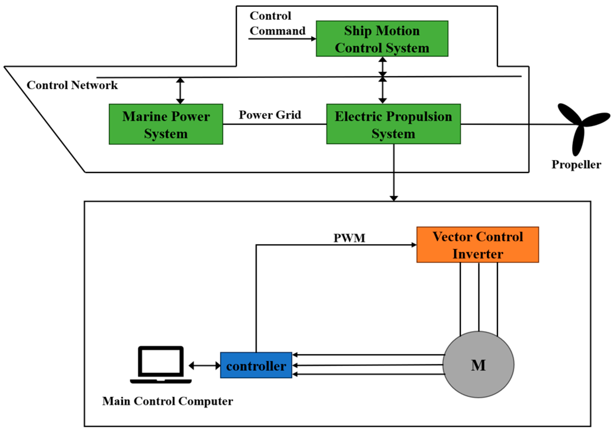
2. Mathematical Modeling of the Three-Phase PMSM for Ship Propulsion System

As illustrated in Figure 1, the electric propulsion system of a ship consists of the ship’s power module, motion control system, and electric propulsion unit. This system relies on the drive mechanism to control the rotational speed of the propulsion motor, thereby regulating the propeller speed and driving forward the vessel.
This paper considers a surface-mounted PMSM as the propulsion motor in the ship’s electric propulsion system. To facilitate the analysis while maintaining the integrity of the mathematical model development for the PMSM, the following assumptions are made:
(1)
The saturation of the motor core is neglected, as well as the eddy current and hysteresis losses within the motor that are disregarded;
(2)
It is assumed that the stator windings are three-phase symmetric, and the magnetic field produced by the rotor’s permanent magnets exhibits a sinusoidal distribution in the air gap;
(3)
It is assumed that the conductivity of the permanent magnets is zero, and their magnetic permeability is considered to be the same as that of air;
(4)
No damping windings are present on the rotor.
Consequently, the stator voltage of the PMSM in the d-q reference frame is expressed as follows:
u d = R i d + L d d i d d t L q ω e i q u q = R i q + L q d i q d t + L d ω e i d + ω e φ f
Moreover, the electromagnetic torque equation is given by:
T e = 3 2 p i q i d L d L q + φ f
As for the mechanical motion equation, it is expressed as follows:
J d ω m d t = T e T L B ω m
where ud, uq, id, iq, Ld, and Lq represent the voltage, current, and inductance components along the d-q axes, respectively. Moreover, R is the stator resistance, φf denotes the magnetic flux linkage of the permanent magnets, ωe highlights the electrical angular velocity of the motor, ωm designates the mechanical angular velocity, Te presents the electromagnetic torque, J is the moment of inertia, TL represents the load torque, and B denotes the damping coefficient.
For the surface-mounted PMSM, Ld = Lq = L. As a result, the electromagnetic torque equation can be expressed as follows:
T e = 3 2 p φ f i q
By adopting the vector control strategy with id = 0, and by substituting (4) into (3), the mathematical model of the PMSM in the d-q reference frame is determined as follows:
d i q d t = 1 L R i q φ f ω e + u q d ω m d t = 3 p φ f 2 J i q T L J B J ω m
As shown in (5), when the control method with id = 0 is employed, the d-q axis voltage, electromagnetic torque, and rotational speed are all exclusively dependent on iq. Consequently, regulating the q-axis current alone is sufficient to control the PMSM, contributing to a great simplification of the control process.

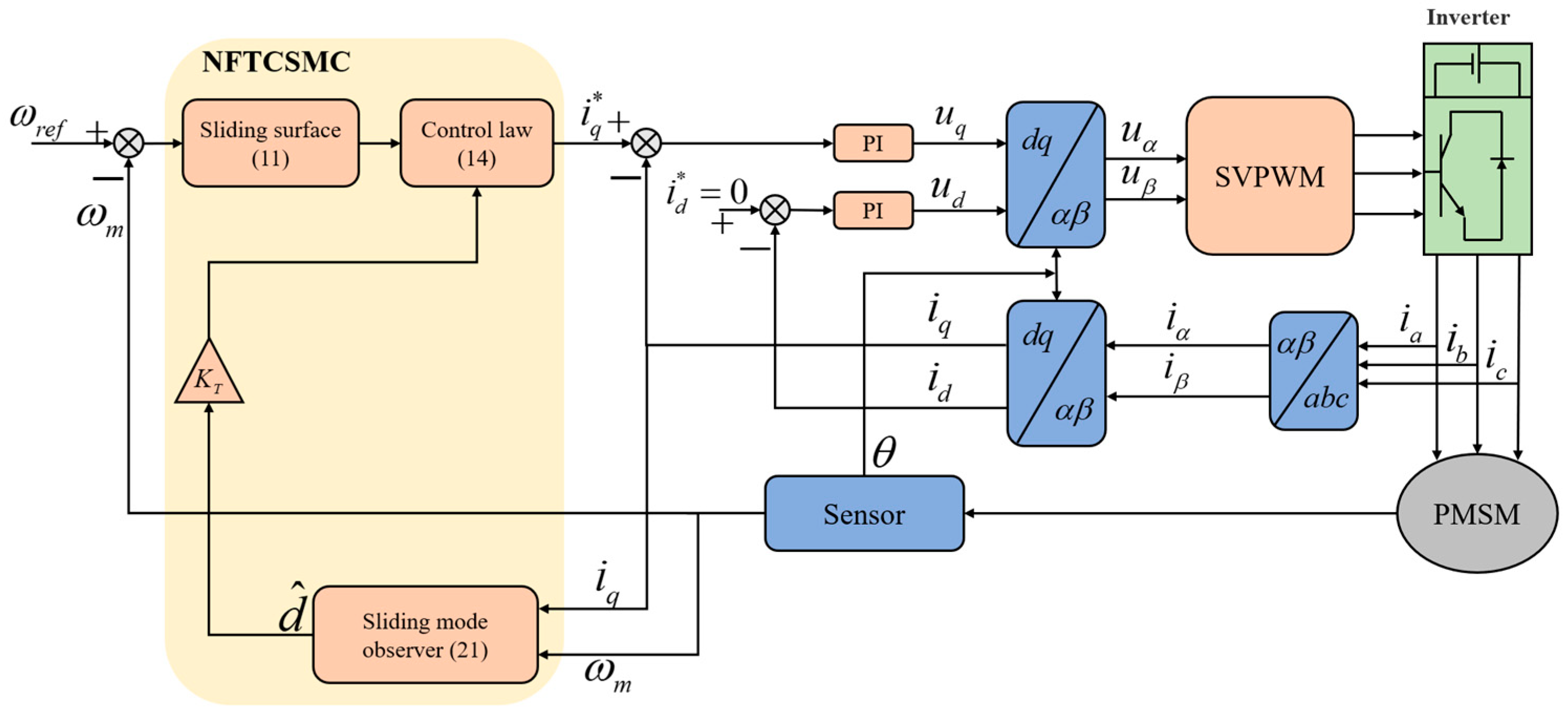
3. Control Strategy of Permanent Magnet Synchronous Propulsion Motor for Ships

Figure 2 illustrates the control block diagram of the PMSM system, where NFTSMC and SMDO replace the PI controller as the speed loop controller. The inner current loop is controlled by PI, and SMDO is used to estimate external disturbances and provide feedforward compensation to the NFTSMC. Finally, the q-axis current output from the controller is adopted as the reference input of the current inner loop.

3.1. Design of IERL

In traditional SMC, a reaching law is commonly employed to conduct the system toward the desired state. The conventional exponential reaching law is expressed as follows:
s ˙ = ε   sgn ( s ) k s
where s represents the sliding surface function, ε and k denote the rate of approach for the equivalent speed term and the coefficient of the exponential approach term, respectively, with both ε and k being greater than zero.
The increase in the relevant coefficients of the conventional exponential reaching law can accelerate the system’s convergence rate, and it inevitably results in significant chattering as the system approaches the sliding surface. This, in turn, hinders the establishment of an optimal trade-off between convergence speed and chattering. Recognizing the inherent limitations of the traditional exponential reaching law in balancing these two factors, this paper introduces an IERL designed to address these challenges:
s ˙ = ε f ( s ) tanh ( s r ) k s γ f ( s ) = x 1 b + ( 1 b ) e δ s
where s represents the sliding mode surface function, ε and k denote the convergence rates for the constant speed term and the exponential term, respectively, with both variables being positive constants. Moreover, γ is the exponent coefficient, which is an odd number greater than the unit, b denotes the adjustable parameter for the convergence law, with 0 < b < 1, δ represents the exponent coefficient of the exponential function, and x1 denotes the state variable of the system.
By substituting the sign function sgn(s) in the traditional reaching law with the continuously differentiable hyperbolic tangent function tanh(s/r), and adopting a variable speed strategy rather than a constant speed approach, a more efficient and adaptive convergence to the sliding mode surface is achieved. This strategy ensures faster convergence over larger distances and slower convergence as the system nears the sliding mode surface, resulting in smoother transitions within the SMC and significantly reducing system chattering.
Therefore, the expression for the hyperbolic tangent function tanh(s/r) is expressed as follows:
tanh ( s r ) = e s r e s r e s r + e s r ,
where r is a positive, undetermined coefficient whose value determines the rate of change in the inflection point of the hyperbolic tangent function. Moreover, Figure 3 presents a comparison between the sgn(s) and the tanh(s/r) functions.

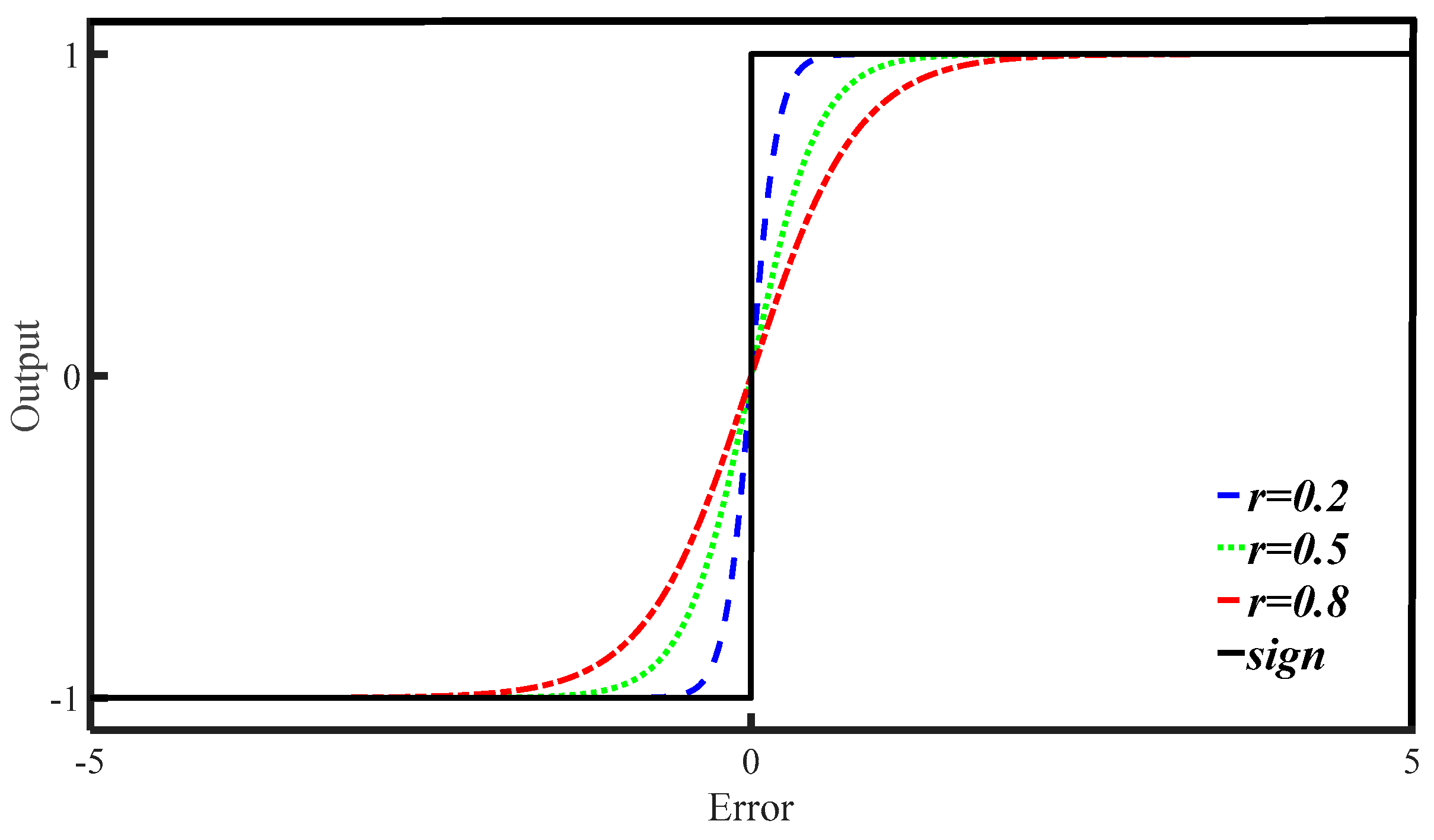
3.2. Design of NFTSMC

The rotational speed tracking error is defined as follows:
x 1 = ω r e f ω m
x ˙ 1 = x 2 = ω ˙ r e f ω ˙ m
where ωref represents the reference speed of the motor and ωm denotes the actual speed.
A non-singular fast terminal sliding mode surface is selected, where the SMC function is defined as follows [39]:
s = x 1 ( t ) + p 0 t x 1 ( τ ) d τ + q 0 t x 1 ( τ ) λ sgn ( x 1 ( τ ) ) d τ
where both p and q are positive constants, and 0 < λ < 1.
Considering the derivatives of (11), one can write:
s ˙ = x 2 + p x 1 + q x 1 λ sgn ( x 1 )
Combining (5), (9), (10) and (12), the derivative of the sliding mode surface is obtained as follows:
s ˙ = 3 p φ f 2 J i q + T L J + B ω m J + p x 1 + q x 1 λ sgn ( x 1 )
From (7) and (13), one can obtain the total control law iq of NFTSMC as follows:
i q = 2 J 3 p φ f [ ε f ( s ) tanh ( s r ) + k s γ + p x 1 + q x 1 λ sgn ( x 1 ) + T L J + B ω m J ]
To demonstrate the stability of the designed controller, the Lyapunov function V = 1 2 S 2 is used for stability analysis. Therefore,
V ˙ = s s ˙ = s ε f ( s ) tanh ( s r ) k s γ 0
From (15), it can be concluded that the designed control system is stable.

3.3. Design of SMDO

During ship navigation, the propulsion motor is subject to internal parameter variations and external disturbances, such as wind, waves, and currents. If these disturbances are not effectively managed, they can degrade the system’s control performance. To address this challenge, this paper proposes a non-singular fast terminal sliding mode disturbance observer, built upon an improved exponential reaching law, for real-time disturbance estimation and compensation. The motor’s speed and current are first sampled by the sensors to estimate the disturbances. These estimated disturbances are then compensated by adjusting the q-axis current through appropriately selected gain parameters, effectively mitigating the impact of external disturbances on motor speed and enhancing the system’s disturbance rejection capability and overall robustness.
Based on the PMSM mechanical motion equation, the mechanical angular velocity ωm of the motor and the total system disturbance d are considered as new state variables. Considering the high sampling frequency during the motor’s operation, and assuming a constant load torque TL representing the total external disturbance d, (3) can be written as follows:
ω ˙ m = T e J B J ω m 1 J d d ˙ = 0
To obtain the observed values of the motor speed and the total external disturbance, (16) is transformed into a matrix form, denoted as follows:
ω ^ ˙ m d ^ ˙ = B J 1 J 0 0 ω ^ m d ^ + 1 J 0 T e + 1 χ g ( e ω )
where ω ^ m represents the observed motor speed, d ^ denotes the total system disturbance observation, g(eω) is the SMC law for the observation error, and χ is the sliding mode disturbance observer gain. By subtracting (16) from (17), the error dynamics of the sliding mode disturbance observer are expressed as follows:
e ˙ ω e ˙ d = B J 1 J 0 0 e ω e d 1 χ g ( e ω ) ,
where e ω = ω m ω ^ m represents the speed observation error and e d = d d ^ denotes the disturbance observation error. The sliding surface and reaching law of SMDO are defined as follows:
s ω = e ω + p ω 0 t e ω d τ + q ω 0 t e ω λ sgn ( e ω ) d τ ,
s ˙ ω = ε ω f ( s ω ) tanh ( s ω r ) k ω s ω γ f ( s ω ) = e ω b + ( 1 b ) e δ s ω ,
Combining (19) and (20), and treating −ed/J as a disturbance term, the control law of the designed SMDO, g(eω) is defined as follows:
g ( e ω ) = ( p ω B J ) e ω + q ω e ω λ sgn ( e ω ) + ε ω f ( s ω ) tanh ( s ω r ) + k ω s ω γ
Defining the Lyapunov function as V = 1 2 S ω 2 to prove the stability of the sliding mode disturbance observer leads to the following:
V ˙ = s ω s ˙ ω = s ω ε ω f ( s ω ) tanh ( s ω r ) k ω s ω γ 0
As demonstrated in (22), the designed SMDO adheres to the Lyapunov stability theory. Given that the observation findings of the SMDO correspond to the load torque, it is required to transform the observed value into the current for the disturbance compensation in the speed controller, thereby establishing a closed-loop feedback system. According to the electromagnetic torque equation shown in (4), the relationship between torque and current is expressed as follows:
i q = K T d ^
Let the output current of the controller in (14) be denoted as i q , then the output of the NFTCSMC is given by:
i q = i q + i q = 1 D [ ε f ( s ) tanh ( s r ) + k s γ + p x 1 + q x 1 λ sgn ( x 1 ) + T L J + B ω m J ] + K T d ^

4. Experimental Verification and Analysis

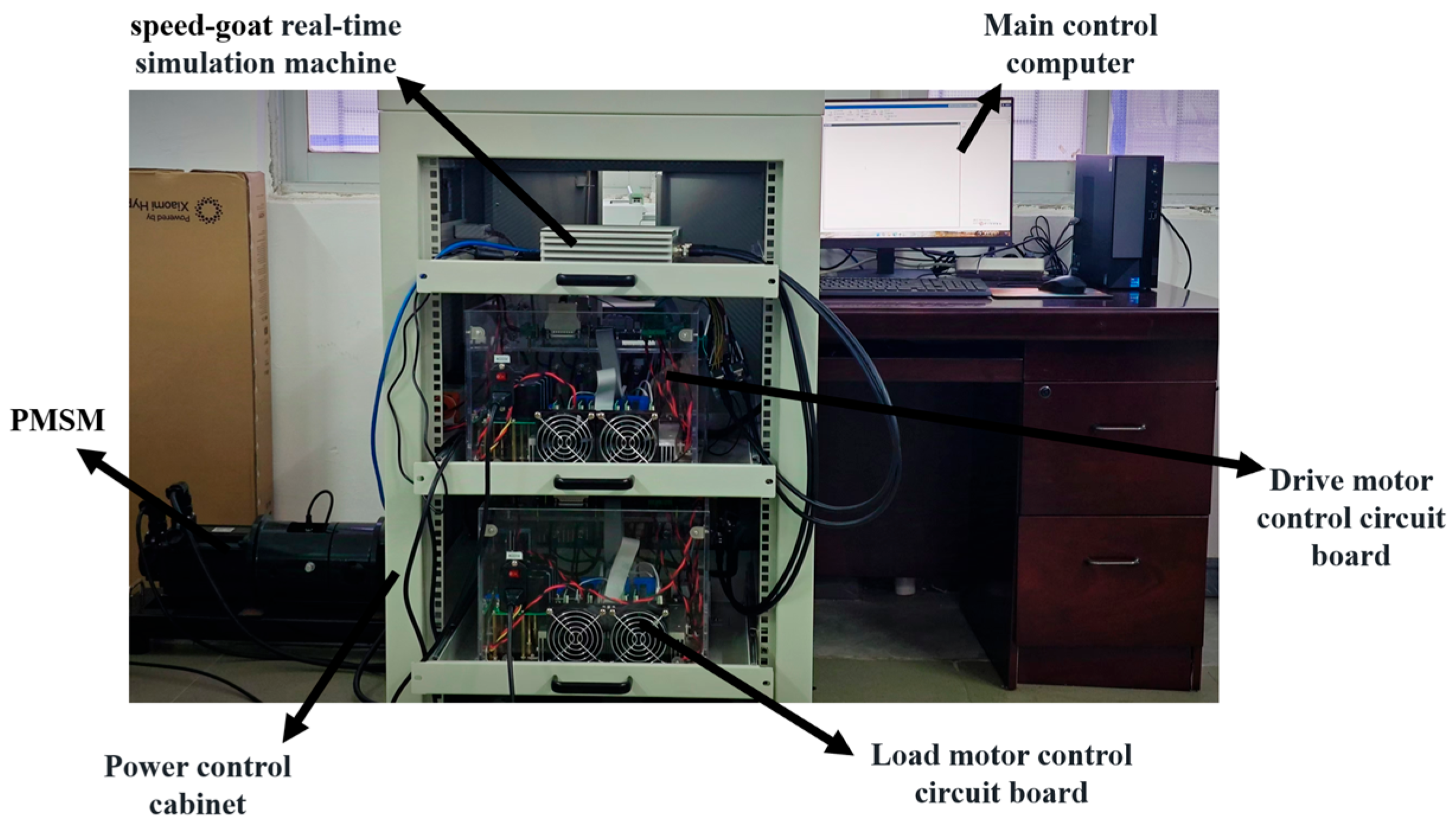
4.1. Experimental Setup

To validate the effectiveness of the NFTCSMC strategy proposed in this work, the designed composite SMC was integrated into the ship’s PMSM propulsion control system. The experimental analysis was conducted employing a semi-physical ship electric propulsion platform. The experimental validation was performed through rapid prototyping control technology. This experimental equipment primarily consists of a master control computer, a speed-goat real-time simulation machine, a PMSM, and a power control cabinet, as illustrated in Figure 4. Moreover, the main parameters of the PMSM are listed in Table 1.
Using the semi-physical experimental platform shown in Figure 4, the control algorithm was designed in MATLAB/Simulink 23.2.0.2365128 (R2023b) on the master control computer. The control code was automatically compiled and generated via the speed-goat real-time simulation machine, facilitating the conversion of the program for actual PMSM control. A monitoring panel was incorporated to record and track various data. After initiating the equipment, the parameters in the NFTCSMC strategy were continuously adjusted through the monitoring panel to control the motor and achieve the desired performance. The recorded data and waveforms were then uploaded to the master control computer for further analysis.
To effectively evaluate the control performance of the three control strategies under different conditions, the initial parameters of the current loop controller refer to ref. [40], optimized and kept consistent. On this basis, the optimal parameters of the speed loop controller are obtained and shown in Table 2.

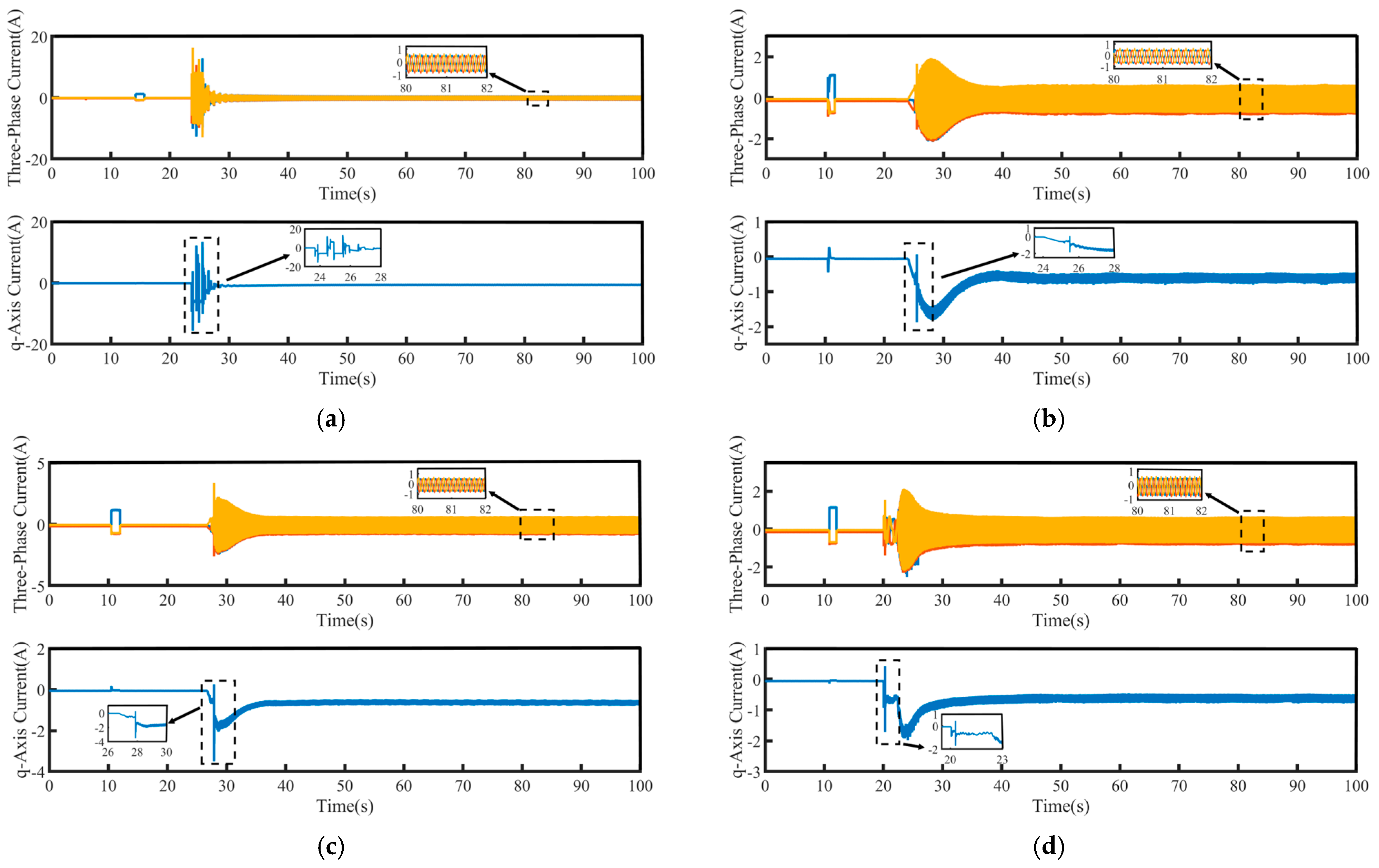
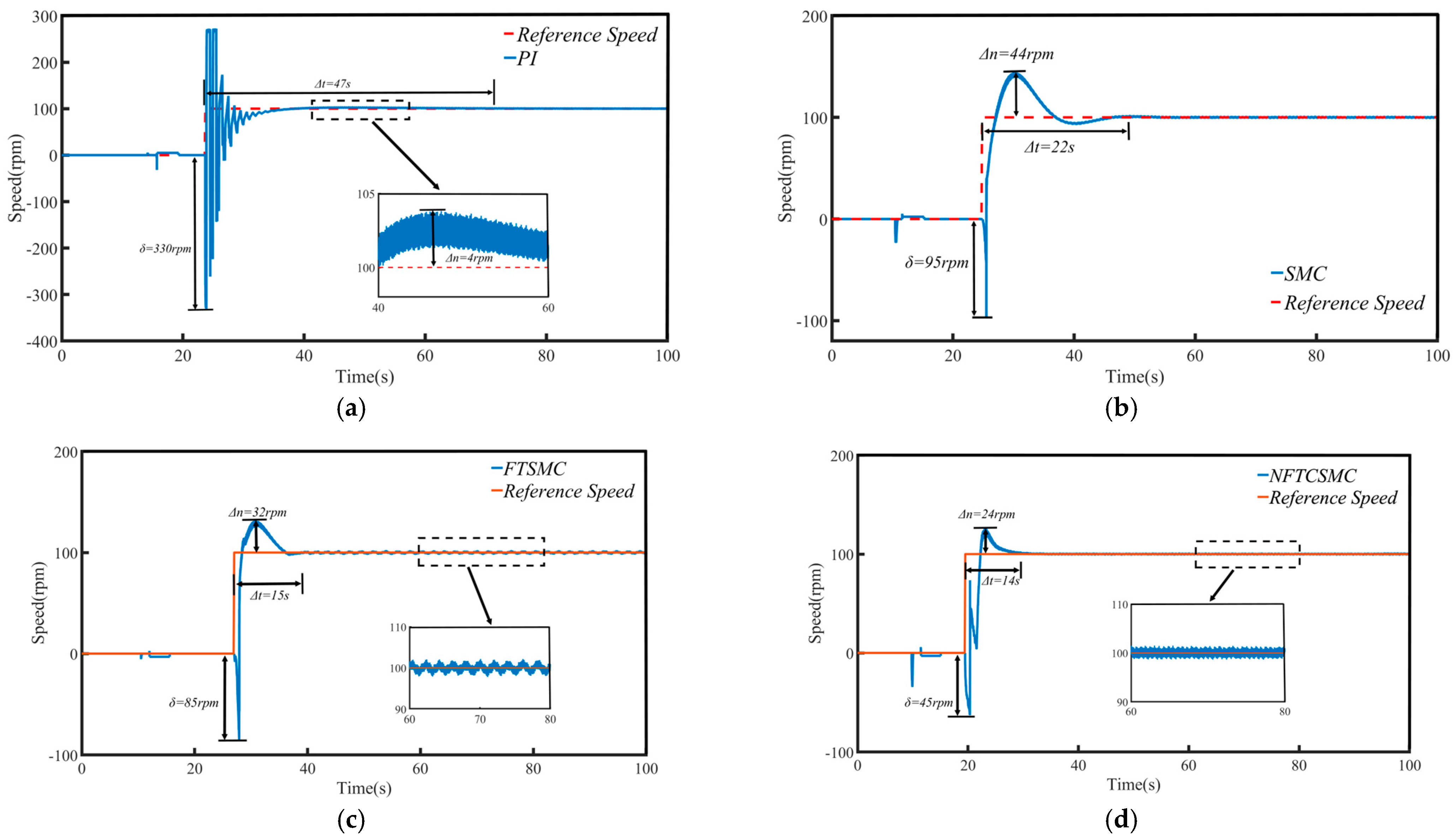
4.2. Start-Up Performance

The propulsion motors in ship electric propulsion systems typically operate under medium- to high-speed conditions. However, it is necessary to conduct a ship’s test for the low-speed startup of the main engine to prevent the excessive starting current generated during motor startup and to ensure the safe operation of the motor. This test serves to evaluate the performance of the control strategy adjustments.
To assess the effectiveness of the proposed control strategy, comparative experiments were conducted on the low-speed startup performance of the PMSM using four control strategies: PI, traditional SMC, FTSMC, and the proposed NFTCSMC, under no-load conditions. The three-phase current and q-axis current of the PMSM for each control strategy are depicted in Figure 5. The startup performance comparison is illustrated in Figure 6, with the results summarized in Table 3, where Δn represents the maximum speed overshoot, Δt denotes the settling time from startup to the target speed, and δ indicates the maximum speed oscillation during the PMSM startup, which is caused by the dynamic response delay of the electromagnetic torque, leading to a brief reverse in speed and a stalling effect before the motor accelerates.
As shown in the magnified view of the q-axis current in Figure 5, compared to the PI, SMC, and FTSMC strategies, the NFTCSMC strategy generates a smaller q-axis current at the moment of motor startup, resulting in a smoother transition and effectively reducing the intense fluctuations in electromagnetic torque. As shown in the magnified view of the three-phase current in Figure 5, under all four control strategies, once the motor reaches the set speed, the three-phase current is able to be output smoothly.
Combined with Figure 6 and Table 3, it is evident that under the PI control strategy, the PMSM starts at a low speed with a relatively small speed overshoot, with only a 4 rpm increase. However, significant speed fluctuations occur during startup, leading to substantial oscillations at low speeds, with the maximum oscillation amplitude reaching 330 rpm, and it takes 47 s to reach the target speed, resulting in a relatively large settling time. In contrast, the traditional SMC, FTSMC, and the proposed NFTCSMC strategies offer superior low-speed startup performance compared to PI control. Specifically, compared to PI control, the traditional SMC reduces oscillations during low-speed startup, with the maximum oscillation amplitude reaching 95 rpm, and it takes 22 s to reach the target speed, thereby shortening the settling time, although it increases speed overshoot. Under the FTSMC strategy, the speed overshoot is reduced to 32 rpm, the maximum oscillation amplitude is 85 rpm, and the time to reach the set speed is only 15 s, thereby improving the dynamic response capability of the PMSM. On the other hand, the NFTCSMC strategy not only reduces speed overshoot but also improves the system’s dynamic response, shortens the settling time, and, compared to the PI, SMC, and FTSMC strategies, reduces the speed fluctuation during the low-speed startup of the PMSM by approximately 86.36%, 52.63%, and 47.06%, respectively, while decreasing the time to reach the set speed by 70.21%, 36.36%, and 6.67%, respectively.

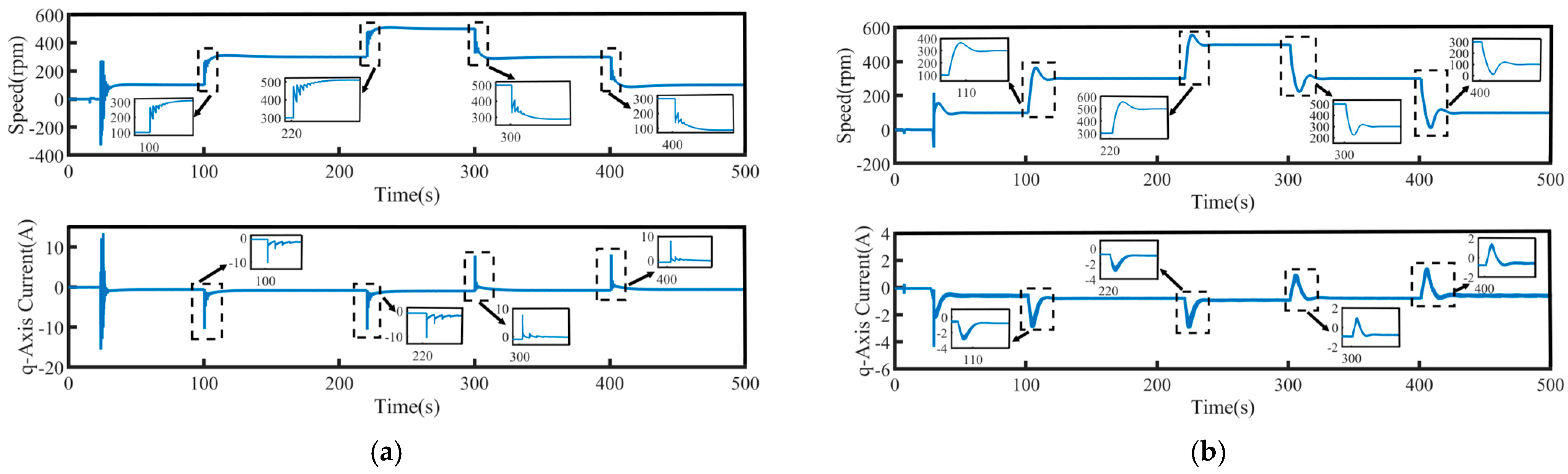
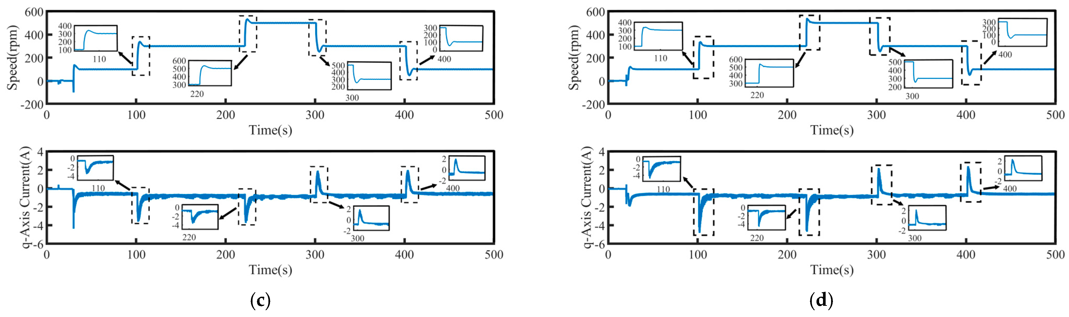
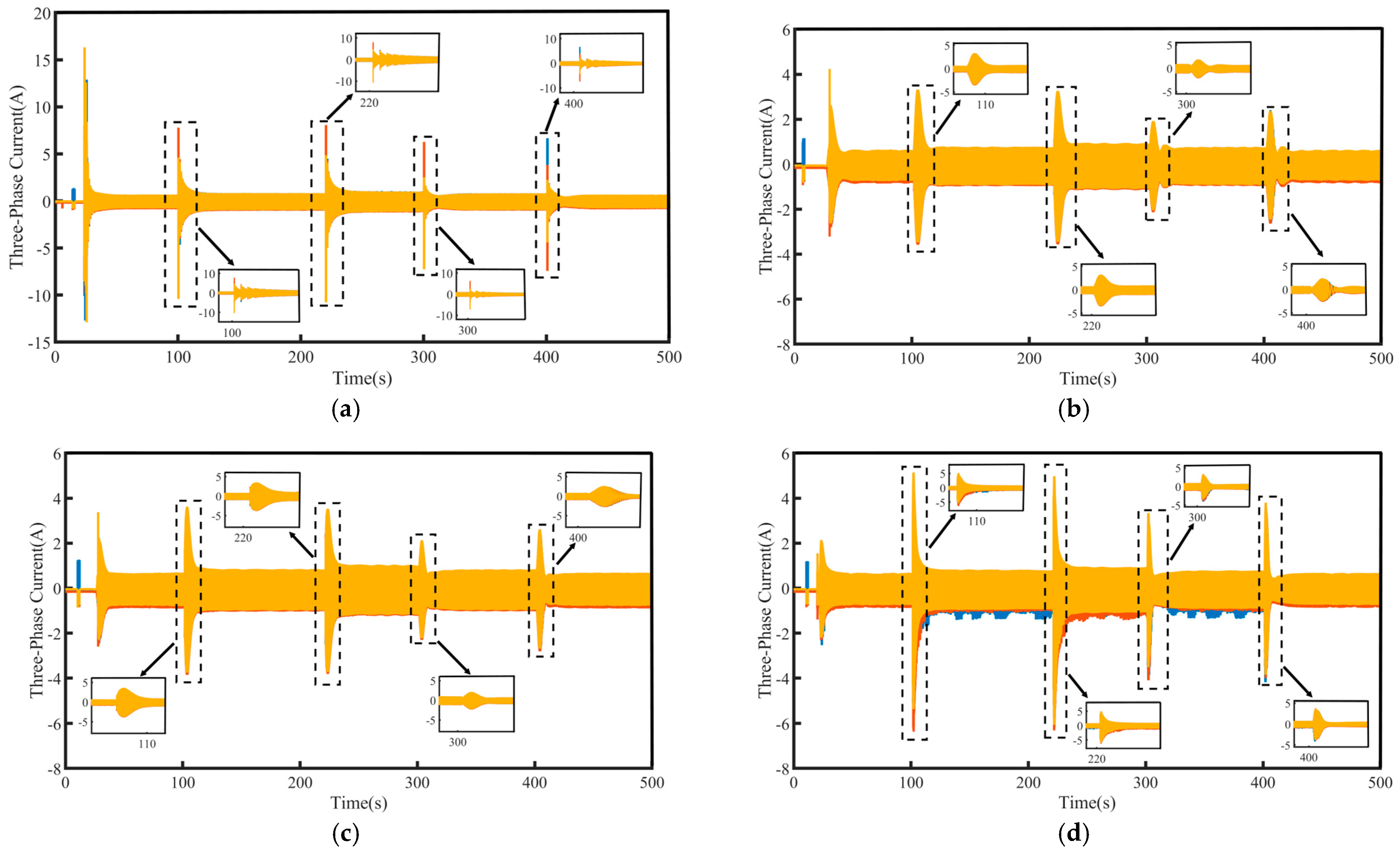
4.3. Speed Command Tracking

To improve the maneuverability, controllability, and stability of electrically powered vessels during navigation, a speed command tracking experiment is performed to simulate the performance of the ship’s main engine under operating conditions. The speed tracking and q-axis current curves for the PI, SMC, FTSMC, and NFTCSMC strategies are shown in Figure 7, while Figure 8 presents a comparison of the three-phase currents for four control strategies. Overall, all four control schemes effectively track the reference speed curve and produce stable torque output.
Although the NFTCSMC strategy exhibits some speed overshoot when the target speed undergoes a sudden change, the overshoot remains within acceptable performance limits, and the settling time to reach the target speed is shorter than that of the other three control methods, as observed from the zoomed-in view of the speed tracking curves under the four control strategies in Figure 7.
From the perspective of the magnified sections in Figure 7 and Figure 8, it can be observed that when there is a sudden change in the propulsion motor speed, the PI control leads to significant speed fluctuations, and the time to reach a stable target speed is relatively long, which negatively affects the control performance of the PMSM. Furthermore, when the motor speed experiences a sudden change, the q-axis current and the three-phase currents fluctuate violently, severely impacting the safe operation of the propulsion motor. Although the SMC strategy eliminates speed oscillations during sudden changes in motor speed, enabling a smooth transition to the target speed without causing violent fluctuations in the q-axis current and three-phase currents, it results in increased overshoot and longer settling time. In contrast, when a sudden change in speed occurs, both the FTSMC and NFTCSMC strategies not only prevent violent fluctuations in the q-axis current and three-phase currents, allowing the speed to transition smoothly to the given value but also reduce overshoot to some extent, significantly shortening the settling time. However, in comparison to FTSMC, NFTCSMC exhibits enhanced dynamic response performance, enabling the system to reach the desired speed more rapidly. This improves the dynamic response capability of the PMSM while ensuring the safe operation of the propulsion motor and demonstrates excellent speed-tracking performance.

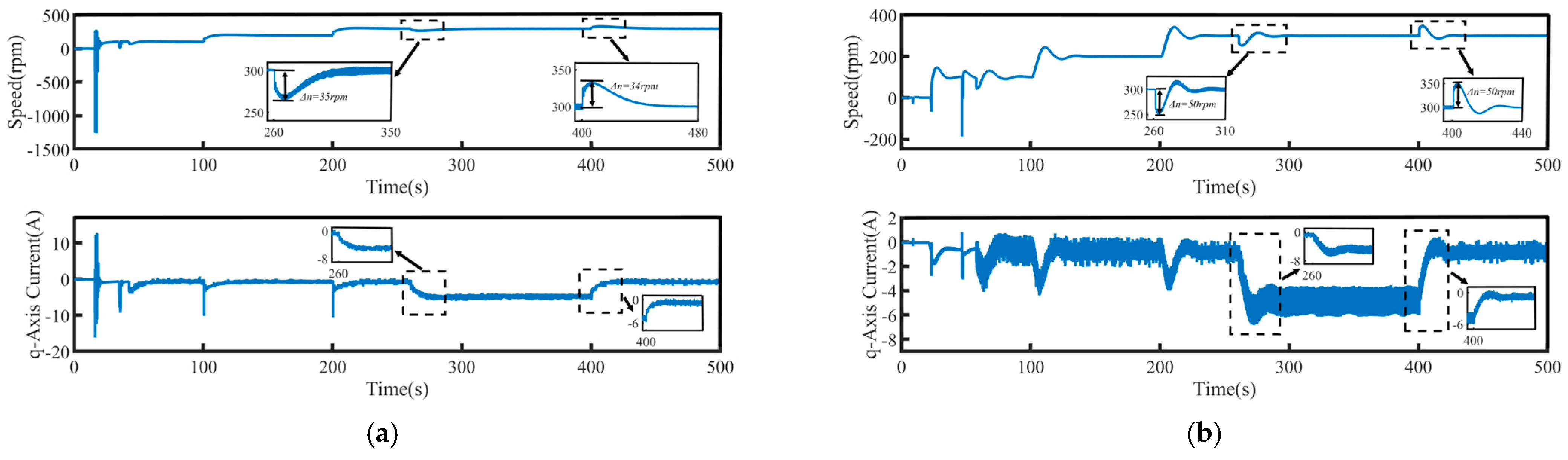
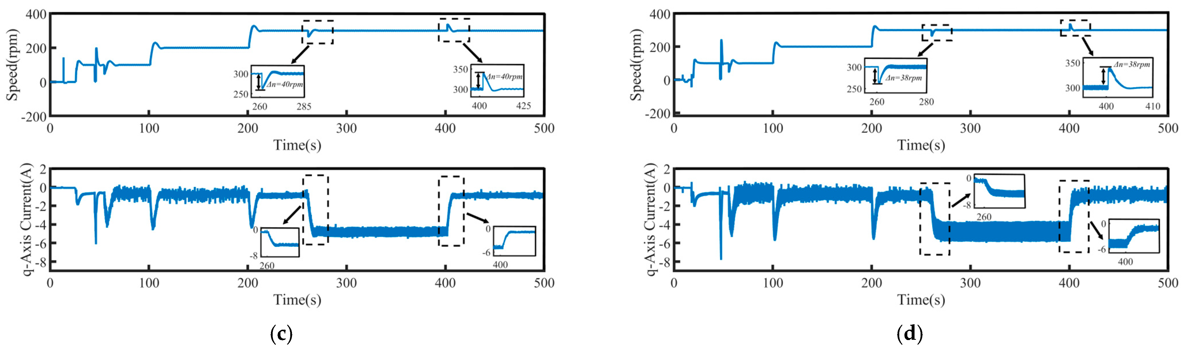
4.4. Load Torque Regulation

During navigation, ships may encounter floating debris or large obstacles. In such cases, in order to maintain the ship’s heading and speed, the propeller torque may suddenly increase, causing a significant impact on the electric propulsion system, and the propulsion motor will also be affected. Therefore, simulating a sudden load increase on the propulsion motor to imitate the propeller being obstructed is necessary to test the adjustment performance of the control strategy. Additionally, when the ship navigates in strong winds, rough seas, or adverse weather conditions, the ship’s resistance can vary greatly, potentially leading to propeller malfunctions such as cavitation or detachment. In such situations, propeller efficiency significantly declines. Thus, simulating a sudden load reduction on the propulsion motor to imitate the propeller idling during navigation in heavy or off-head seas is crucial for testing the control strategy’s adjustment performance.
To validate the system’s robustness, a 5 N·m load disturbance is applied to the system at 260 s, and then removed at 400 s. The speed tracking and q-axis current curves under the four control schemes are shown in Figure 9, where Δn represents the maximum change in speed when the load undergoes a sudden change. The maximum variations in rotational speed and the longest stabilization time during load disturbances for each control method are summarized in Table 4, where Δt represents the maximum stabilization time in speed when the load undergoes a sudden change. Figure 10 presents a comparison of the three-phase currents under the four control schemes. Overall, even under disturbance conditions, all four control methods are still able to effectively track the target speed, demonstrating a certain level of robustness.
From the enlarged views in Figure 9 and Figure 10, it can be observed that when a sudden load is applied, the motor speed under PI control decreases by 35 rpm, accompanied by significant speed oscillations. The changes in the q-axis current and three-phase currents are relatively slow, resulting in a relatively long settling time to reach the target speed, taking 90 s. Although under the SMC strategy, when a sudden load is applied, the q-axis current and three-phase current change rapidly, shortening the settling time, the propulsion motor speed decreases by 50 rpm, accompanied by significant speed fluctuation. In contrast, under the NFTCSMC strategy, although the motor speed decreases by 38 rpm—slightly more than under PI control—the speed oscillations during sudden load application are eliminated, while ensuring the q-axis current and three-phase current change rapidly, and the settling time is significantly reduced, requiring only 20 s. Compared to the other three control methods, the settling time is reduced by approximately 77.78 percent, 60 percent, and 20 percent, respectively. When the load is suddenly removed, the motor speeds under PI, SMC, FTSMC, and NFTCSMC strategy increase by 34 rpm, 50 rpm, 40 rpm, and 38 rpm, respectively. Compared to PI, SMC, and FTSMC strategies, the NFTCSMC strategy reduces the settling time to reach the set speed by approximately 87.5 percent, 75 percent, and 60 percent, respectively, under sudden load reduction.
The experimental results indicate that the NFTCSMC strategy demonstrates better tracking accuracy, stronger anti-interference capabilities, and robustness, making it more suitable for meeting the demands of ship navigation in harsh environments and weather conditions.

5. Conclusions

This paper proposes an improved exponential approach law to address the issue in traditional sliding mode control, where it is difficult to balance the convergence speed with the chattering effect. Based on this, a non-singular fast terminal composite sliding mode control strategy is proposed. Meanwhile, to address the impact of external disturbances on the PMSM, a non-singular fast terminal sliding mode disturbance observer is proposed to monitor the external disturbances in real time and feed forward the observed values into the speed loop, further enhancing the anti-disturbance capability and robustness. Experimental results show that the proposed NFTCSMC strategy exhibits stronger dynamic response and anti-interference capability, improving the system’s robustness and stability, and overall enhancing the dynamic performance of the ship’s electric propulsion system.

Author Contributions

Conceptualization, Z.L. and Y.X.; methodology, Z.L. and Y.X.; validation, Z.L. and Y.X.; formal analysis, L.A., Z.Z. and B.J.; investigation, X.W. and P.Z.; resources, Y.X. and B.J.; data curation, Z.L. and X.W.; writing—original draft preparation, Z.L.; writing—review and editing, Z.L. and Y.X.; visualization, Z.L. and Y.X.; supervision, Y.X. and B.J.; project administration, Y.X.; funding acquisition, Y.X. All authors have read and agreed to the published version of the manuscript.

Funding

This research was supported in part by the Natural Science Foundation of Guangdong province under Grant 2023A1515012056, in part by the Young Creative Talents Project of Zhanjiang under Grant 2022E05001, in part by the program for scientific research start-up funds of Guangdong Ocean University under Grant 060302132307, and in part by the National Nature Science Foundation of China under Grant 52071090, and in part by the Guangdong Provincial Department of Education 2023 high-end equipment manufacturing key areas of ordinary colleges and universities 2023ZDZX3003 (Corresponding author: Yuanyuan Xu).

Data Availability Statement

The original contributions presented in this study are included in the article.

Conflicts of Interest

The authors declare no conflicts of interest.

References

  1. Zhang, Z.; Guo, H.; Liu, Y.; Zhang, Q.; Zhu, P.; Iqbal, R. An Improved Sensorless Control Strategy of Ship IPMSM at Full Speed Range. IEEE Access 2019, 7, 178652–178661. [Google Scholar] [CrossRef]
  2. Wang, Y.; Liu, Y.; Ding, J.; Wang, D. Adaptive type-2 fuzzy output feedback control using nonlinear observers for permanent magnet synchronous motor servo systems. Eng. Appl. Artif. Intell. 2024, 131, 107833. [Google Scholar] [CrossRef]
  3. Cheng, S.; Yu, J.; Zhao, L.; Ma, Y. Adaptive fuzzy control for permanent magnet synchronous motors considering input saturation in electric vehicle stochastic drive systems. J. Frankl. Inst. 2020, 357, 8473–8490. [Google Scholar] [CrossRef]
  4. Li, B.; Zhao, B. Neural Network-Based Adaptive Sliding Mode Control for T-S Fuzzy Fractional Order Systems. IEEE Trans. Circuits Syst. II Express Briefs 2023, 70, 4549–4553. [Google Scholar] [CrossRef]
  5. Brosch, A.; Wallscheid, O.; Böcker, J. Time-Optimal Model Predictive Control of Permanent Magnet Synchronous Motors in the Whole Spe-ed and Modulation Range Considering Current and Torque Limits. IEEE Open J. Ind. Electron. Soc. 2023, 4, 643–658. [Google Scholar] [CrossRef]
  6. Li, T.; Sun, X.; Yao, M.; Guo, D.; Sun, Y. Improved Finite Control Set Model Predictive Current Control for Permanent Magnet Synchronous Motor with Sliding Mode Observer. IEEE Trans. Transp. Electrif. 2024, 10, 699–710. [Google Scholar] [CrossRef]
  7. He, L.; Wang, F.; Ke, D. FPGA-Based Sliding-Mode Predictive Control for PMSM Speed Regulation System Using an Adaptive Ultralocal Model. IEEE Trans. Power Electron. 2021, 36, 5784–5793. [Google Scholar] [CrossRef]
  8. Xu, Y.; Yan, Z.; Zhang, Y.; Song, R. Model Predictive Current Control of Permanent Magnet Synchronous Motor Based on Sliding Mode Observer with Enhanced Current and Speed Tracking Ability Under Disturbance. IEEE Trans. Energy Convers. 2023, 38, 948–958. [Google Scholar] [CrossRef]
  9. Zhang, Y.; Yin, Z.; Li, W.; Liu, J.; Zhang, Y. Adaptive Sliding-Mode-Based Speed Control in Finite Control Set Model Predictive Torque Control for Induction Motors. IEEE Trans. Power Electron. 2021, 36, 8076–8087. [Google Scholar] [CrossRef]
  10. Junejo, A.K.; Xu, W.; Mu, C.; Ismail, M.M.; Liu, Y. Adaptive Speed Control of PMSM Drive System Based a New Sliding-Mode Reaching Law. IEEE Trans. Power Electron. 2020, 35, 12110–12121. [Google Scholar] [CrossRef]
  11. Wang, L.; Zhu, Z.; Bin, H.; Gong, L. Current Harmonics Suppression Strategy for PMSM with Nonsinusoidal Back-EMF Based on Adaptive Linear Neuron Method. IEEE Trans. Ind. Electron. 2020, 67, 9164–9173. [Google Scholar] [CrossRef]
  12. Nguyen, T.H.; Nguyen, T.T.; Nguyen, V.Q.; Le, K.M.; Tran, H.N.; Jeon, J.W. An Adaptive Sliding-Mode Controller with a Modified Reduced-Order Proportional Integral Observer for Speed Regulation of a Permanent Magnet Synchronous Motor. IEEE Trans. Ind. Electron. 2022, 69, 7181–7191. [Google Scholar] [CrossRef]
  13. Yeam, T.-I.; Lee, D.-C. Design of Sliding-Mode Speed Controller with Active Damping Control for Single-Inverter Dual-PMSM Drive Systems. IEEE Trans. Power Electron. 2021, 36, 5794–5801. [Google Scholar] [CrossRef]
  14. Guo, X.; Huang, S.; Lu, K.; Peng, Y.; Wang, H.; Yang, J. A Fast Sliding Mode Speed Controller for PMSM Based on New Compound Reaching Law with Improved Sliding Mode Observer. IEEE Trans. Transp. Electrif. 2023, 9, 2955–2968. [Google Scholar] [CrossRef]
  15. Chen, S.; Chiang, H.; Liu, T.; Chang, C. Precision Motion Control of Permanent Magnet Linear Synchronous Motors Using Adaptive Fuzzy Fractional-Order Sliding-Mode Control. IEEE/ASME Trans. Mechatron. 2019, 24, 741–752. [Google Scholar] [CrossRef]
  16. Zhang, Z.; Yang, X.; Wang, W.; Chen, K.; Cheung, N.; Pan, J. Enhanced Sliding Mode Control for PMSM Speed Drive Systems Using a Novel Adaptive Sliding Mode Reaching Law Based on Exponential Function. IEEE Trans. Ind. Electron. 2024, 71, 11978–11988. [Google Scholar] [CrossRef]
  17. Sun, X.; Cao, J.; Lei, G.; Guo, Y.; Zhu, J. A Composite Sliding Mode Control for SPMSM Drives Based on a New Hybrid Reaching Law with Disturbance Compensation. IEEE Trans. Transp. Electrif. 2021, 7, 1427–1436. [Google Scholar] [CrossRef]
  18. Wang, Y.; Feng, Y.; Zhang, X.; Liang, J. A New Reaching Law for Antidisturbance Sliding-Mode Control of PMSM Speed Regulation System. IEEE Trans. Power Electron. 2020, 35, 4117–4126. [Google Scholar] [CrossRef]
  19. Xu, W.; Junejo, A.K.; Liu, Y.; Hussien, M.G.; Zhu, J. An Efficient Antidisturbance Sliding-Mode Speed Control Method for PMSM Drive Systems. IEEE Trans. Power Electron. 2021, 36, 6879–6891. [Google Scholar] [CrossRef]
  20. Ma, Y.; Li, D.; Li, Y.; Yang, L. A Novel Discrete Compound Integral Terminal Sliding Mode Control with Disturbance Compensation for PMSM Speed System. IEEE/ASME Trans. Mechatron. 2022, 27, 549–560. [Google Scholar] [CrossRef]
  21. Hou, H.; Yu, X.; Xu, L.; Rsetam, K.; Cao, Z. Finite-Time Continuous Terminal Sliding Mode Control of Servo Motor Systems. IEEE Trans. Ind. Electron. 2020, 67, 5647–5656. [Google Scholar] [CrossRef]
  22. Zou, Q.; Chang, S. A new fixed-time terminal sliding mode control for second-order nonlinear systems. J. Frankl. Inst. 2024, 361, 1255–1267. [Google Scholar] [CrossRef]
  23. Cruz-Ortiz, D.; Chairez, I.; Poznyak, A. Non-singular terminal sliding-mode control for a manipulator robot using a barrier Lyapunov function. ISA Trans. 2022, 121, 268–283. [Google Scholar] [CrossRef] [PubMed]
  24. Hagh, Y.S.; Fekih, A.; Handroos, H. Robust PI-Based Non-Singular Terminal Synergetic Control for Nonlinear Systems via Hybrid Nonlinear Disturbance Observer. IEEE Access 2021, 9, 97401–97414. [Google Scholar] [CrossRef]
  25. Fu, D.; Zhao, X.; Zhu, J. A Novel Robust Super-Twisting Nonsingular Terminal Sliding Mode Controller for Permanent Magnet Linear Synchronous Motors. IEEE Trans. Power Electron. 2022, 37, 2936–2945. [Google Scholar] [CrossRef]
  26. Xu, B.; Zhang, L.; Ji, W. Improved Non-Singular Fast Terminal Sliding Mode Control with Disturbance Observer for PMSM Drives. IEEE Trans. Transp. Electrif. 2021, 7, 2753–2762. [Google Scholar] [CrossRef]
  27. Hagras, A.A.; Azab, A.; Zaid, S. Model-Free Nonsingular Fast Terminal Sliding Mode Control of a Permanent Magnet Synchronous Motor. Acta Polytech. Hung. 2024, 21, 283–305. [Google Scholar] [CrossRef]
  28. Wang, Y.; Chen, H.; Zhang, M.; Chen, B.; Jia, R.; Mao, J. Non-singular fast terminal sliding mode control of PMSMs with disturbance compensation. J. Power Electron. 2024, 1–11. [Google Scholar] [CrossRef]
  29. Yin, Y.; Liu, L.; Vazquez, S.; Xu, R.; Dong, Z.; Liu, J.; Leon, J.I.; Wu, L.; Franquelo, L.G. Disturbance and Uncertainty Attenuation for Speed Regulation of PMSM Servo System Using Adaptive Optimal Control Strategy. IEEE Trans. Transp. Electrif. 2023, 9, 3410–3420. [Google Scholar] [CrossRef]
  30. Lin, X.; Wu, C.; Yao, W.; Liu, Z.; Shen, X.; Xu, R.; Sun, G.; Liu, J. Observer-Based Fixed-Time Control for Permanent-Magnet Synchronous Motors with Parameter Uncertainties. IEEE Trans. Power Electron. 2023, 38, 4335–4344. [Google Scholar] [CrossRef]
  31. Qu, L.; Qiao, W.; Qu, L. Active-Disturbance-Rejection-Based Sliding-Mode Current Control for Permanent-Magnet Synchronous Motors. IEEE Trans. Power Electron. 2021, 36, 751–760. [Google Scholar] [CrossRef]
  32. Lin, X.; Huang, W.; Jiang, W.; Zhao, Y.; Zhu, S. A Stator Flux Observer with Phase Self-Tuning for Direct Torque Control of Permanent Magnet Synchronous Motor. IEEE Trans. Power Electron. 2020, 35, 6140–6152. [Google Scholar] [CrossRef]
  33. Ke, D.; Wang, F.; He, L.; Li, Z. Predictive Current Control for PMSM Systems Using Extended Sliding Mode Observer with Hurwitz-Based Power Reaching Law. IEEE Trans. Power Electron. 2021, 36, 7223–7232. [Google Scholar] [CrossRef]
  34. Chen, L.; Jin, Z.; Shao, K.; Wang, H.; Wang, G.; Lu, H.; Fernando, T. Sensorless Fixed-Time Sliding Mode Control of PMSM Based on Barrier Function Adaptive Super-Twisting Observer. IEEE Trans. Power Electron. 2024, 39, 3037–3051. [Google Scholar] [CrossRef]
  35. Zhang, L.; Tao, R.; Zhang, Z.; Chien, Y.; Bai, J. PMSM non-singular fast terminal sliding mode control with disturbance compensation, Information Sciences. Inf. Sci. 2023, 642, 119040. [Google Scholar] [CrossRef]
  36. Gil, J.; You, S.; Lee, Y.; Kim, W. Nonlinear sliding mode controller using disturbance observer for permanent magnet synchronous motors under disturbance. Expert Syst. Appl. 2023, 214, 119085. [Google Scholar] [CrossRef]
  37. Liu, Y.C. Disturbance-Observer-Based Sliding-Mode Speed Control for Synchronous Reluctance Motor Drives via Generalized Super-Twisting Algorithm. Actuators 2024, 13, 233. [Google Scholar] [CrossRef]
  38. Zhang, J.; Liu, C.; Chen, S.; Zhang, L. Research on Speed Control of Switched Reluctance Motors Based on Improved Super-Twisting Sliding Mode and Linear Active Disturbance Rejection Control. Electronics 2025, 14, 1065. [Google Scholar] [CrossRef]
  39. Chen, Y.; Liu, J.; Yao, Z. PMSM Sliding Mode Control Based on Disturbance Observer and New Non-Singular Fast Terminal. Modul. Mach. Tool Autom. Manuf. Tech. 2022, 3, 84–87. (In Chinese) [Google Scholar]
  40. Qu, Y.; Zhang, B.; Chu, H.; Shen, H.; Zhang, J.; Yang, X. Sliding-mode anti-disturbance speed control of permanent magnet synchronous motor based on an advanced reaching law. ISA Trans. 2023, 139, 436–447. [Google Scholar] [CrossRef]
Figure 1. Basic structure of ship electric propulsion system.
Machines 13 00470 g001
Figure 2. Control Block Diagram of PMSM System.
Machines 13 00470 g002
Figure 3. A comparison between the function graphs.
Machines 13 00470 g003
Figure 4. Semi-physical experimental platform of ship electric propulsion system.
Machines 13 00470 g004
Figure 5. Three-Phase and q-axis currents of PMSM during no-load low-speed startup: (a) PI, (b) SMC, (c) FTSMC and (d) NFTCSMC.
Machines 13 00470 g005
Figure 6. Speed of PMSM during no-load low-speed startup: (a) PI, and (b) SMC, (c) FTSMC, and (d) NFTCSMC.
Machines 13 00470 g006
Figure 7. Speed command tracking waveforms of the PMSM: (a) PI, (b) SMC, (c) FTSMC, and (d) NFTCSMC.
Machines 13 00470 g007aMachines 13 00470 g007b
Figure 8. Three-phase current waveforms under speed tracking: (a) PI, (b)SMC, (c) FTSMC, and (d) NFTCSMC.
Machines 13 00470 g008
Figure 9. Speed tracking waveforms of PMSM under load disturbance: (a) PI, (b) SMC, (c) FTSMC, and (d) NFTCSMC.
Machines 13 00470 g009aMachines 13 00470 g009b
Figure 10. Three-phase current waveforms under load disturbance: (a) PI, (b) SMC, (c) FTSMC, and (d) NFTCSMC.
Machines 13 00470 g010
Table 1. Parameters of the PMSM Prototype.
ItemMain Parameters
Stator Resistance Rs1.29 Ω
Rated Speed ωN1500 rpm
d-axis Inductance Ld2.53 mH
q-axis Inductance Lq2.53 mH
Number of pole pairs Pn4
Moment of Inertia J0.00194 kg·m2
Permanent Magnet Flux Linkage φf0.2 Wb
Rated power1.5 Kw
Rated current6 A
Rated torque10 Nm
Table 2. Parameters of controller.
Control StrategyController Parameters
PIP = 0.08, I = 0.05
SMCc = 10, ε = 10, q = 20
FTSMCp = 9, q = 1, α = 3.5, β = 7, k = 5, ε = 12
NFTCSMCp = 3.5, q = 3.5, λ = 0.5, k = 5, ε = 3, r = 1.5, b = 0.5, δ = 0.4, γ = 1.1, pω = 5, qω = 5, kω = 20, εω = 5
Table 3. Start-up performance comparison of the PMSM.
Three Control StrategiesPISMCFTSMCNFTCSMC
Δn (rpm)4443224
Δt (s)47221514
δ (rpm)330958545
Table 4. Load torque regulation performance comparison of the PMSM.
Three Control StrategiesPISMCFTSMCNFTCSMC
Sudden loadingΔn (rpm)35504038
Δt (s)90502520
Sudden unloadingΔn (rpm)34504038
Δt (s)80402510
Disclaimer/Publisher’s Note: The statements, opinions and data contained in all publications are solely those of the individual author(s) and contributor(s) and not of MDPI and/or the editor(s). MDPI and/or the editor(s) disclaim responsibility for any injury to people or property resulting from any ideas, methods, instructions or products referred to in the content.

