1. Introduction
The International Maritime Organization (IMO) has mandated that carbon dioxide emissions be reduced from 2008 levels by at least 40% by 2030 in compliance with the Paris Agreement. There are several ways to achieve these requirements, the most popular being engine de-rating and slow steaming [
1]. Older ships are equipped with stronger engines, and according to the requirements of the IMO organization, ships must sail at a reduced speed close to the barred speed range (BSR). Newer ships are equipped with reduced power engines that take longer to pass through the BSR. In both cases, additional attention should be paid to the lifetime assessment.
Marine propulsion shafting systems play a fundamental role in ship propulsion, transmitting power from the main engine to the propeller. These shafts are subjected to complex loading conditions, primarily involving torsional and bending vibrations. Over time, cyclic loading can lead to fatigue damage, potentially causing failures that compromise operational safety and lead to costly maintenance or replacements. Ensuring the structural integrity of propulsion shafts requires accurate fatigue assessment methods, particularly when considering the interplay of torsional and bending loads.
Traditional fatigue assessments of marine propulsion shafting often rely on simplified analytical models [
2,
3], primarily addressing torsional vibrations. These models provide an effective first approximation of the dynamic response and fatigue loading, but often neglect the influence of coupled vibrations. The classical approach, widely used in the maritime industry, considers torsional cyclic stresses as the dominant fatigue contributor, assuming that high-cycle fatigue (HCF) damage is primarily driven by torsional vibration amplitudes. This approach forms the basis of classification society guidelines, such as those outlined by Det Norske Veritas (DNV) [
4]. However, real-world observations and recent research suggest that bending stresses—induced by draught change [
5], ship hull deformations [
6,
7], and specific alignment procedures [
8,
9]—can significantly contribute to fatigue damage in intermediate shafts. The coupling between torsional and lateral vibrations has been recognized in recent studies [
10,
11] as a factor that can exacerbate fatigue damage.
DNV’s fatigue assessment methodology primarily considers torsional vibrations, with cyclic torsional stresses derived from forced vibration analysis. According to DNV, the HCF assessment is based on a comparison between the forced torsional vibration response curve and the allowable stress limit curve, assuming that the shaft system should withstand between
and
cycles during its service life. Bending stresses are generally considered secondary and are typically addressed within the framework of shaft alignment calculation methods [
12]. This separation of torsional and bending stress analysis is reflected in the guidelines of nearly all classification societies [
13,
14]. As a result, it is common in shipyards for one team to handle torsional vibration analysis, while another focuses on shaft alignment. Without proper coordination, this compartmentalized approach can lead to the underestimation of bending stresses.
Main Aim of the Work and Principal Conclusions
This study, initially motivated by the idea of investigating the dangers of operating a ship in slow steaming mode, critically examines DNV’s practice of including bending stress cycles in fatigue assessment and estimates their partial contribution to the overall fatigue life. While considering DNV’s methodology for HCF fatigue assessment, the idea for our own methodology for HCF assessment emerged. In this paper, the methodologies are applied to the example of the flange fillet of the intermediate shaft in a directly coupled plant with a fixed pitch propeller. The following is a review of the applied research methodologies with the aim of comparing them and answering the question of whether and to what extent the influence of bending stresses in the fatigue life assessment of the marine propulsion shafting of a 20,000 DWT ship is significant:
- 0.
Initial calculation:
- 1.
DNV HCF Approach:
Calculation of Torsional and bending fatigue strength curves, identification of needed coefficients;
Calculation of speed-dependent permissible torsional stress limits with bending stress contribution;
Calculation of Safety factor in speed domain.
- 2.
Proposed Biaxial Stress HCF Approach:
Definition of median S-N curve, correction of S-N curve due to reliability and dimension correction factors;
Detailed FE calculation of intermediate shaft flange fillet due to torsional and bending moments for given speed of continuous operation;
Calculation of safety factor in life domain, according to corrected S-N curve at cycles, Miner curve approach above cycles and equivalent von Mises multi-axial stress approach.
From all of this, the following contributions of this work can be seen:
In the DNV approach, in the definition of the expression for permissible torsional stresses with the influence of bending stresses independent of speed and the definition of the safety factor in the speed domain with an implicit life of cycles.
In the proposed approach, in the definition of the corrected S-N curve, in accounting for the reliability and size factors, and in the definition of the safety factor in the life domain based on equivalent stresses.
In the comparison of two safety factors defined in different domains.
The rest of this paper is organized as follows:
Section 2 first defines the characteristics of the propulsion system, including the main engine. Then, two FE models of the propulsion system are set up: one for torsional vibration analysis and the other for static bending analysis. Then, the influence of hull deformation on the bending moments of the propulsion shaft line is considered. The methodology for assessing low- and high-cycle fatigue according to DNV is presented below, and this section ends with the proposed methodology for assessing HCF due to biaxial cyclic torsional and bending stresses.
Section 3 presents a comparison of the obtained results of the HCF fatigue assessment according to DNV and the proposed methodology.
Section 4 ends with conclusions.
2. Materials and Methods
In this study, a low-speed two-stroke engine with a direct-coupled, fixed-pitch propeller setup is considered. The basic main engine and propeller characteristics are given in
Table 1. All other data needed for the torsional equivalent model of the propulsion system can be found in the reference [
15]. The propulsion system is equipped with a torsional vibration damper (TVD), a Geislinger D280/FL, on the free side of the engine crankshaft. Lengths of intermediate and propeller shafts are 7.21 and 6.69 m, respectively. The torsional excitation of the propulsion shaft by the engine is defined by tangential pressure harmonics and phase angles according to given firing order. The first two harmonics of lateral forces, bending, and torsional moments excite the shaft line at the propeller.
2.1. Propulsion Shaft FE Model
In this study, two models are considered. The first includes only torsional degrees of freedom and has a total of 13 nodes. This model is originally built in openTorsion [
16], but is later verified with a torsional vibration model prepared in Ansys Mechanical 2024R2. In the second bending model, the complexity was increased by introducing additional nodes in order to introduce bearing positions and perform bending analysis. The second model has 28 nodes. Both models are shown in
Figure 1. Data for the first torsional model can be found in the literature [
15]. Shaft element and lumped mass parameters for the second bending model are shown in
Table 2 and
Table 3. In
Figure 1b, the arrows pointing down indicate the positions of the radial bearings. Additionally, the arrow shown approximately in the middle of the intermediate shaft indicates the standard gravity applied to all shaft and lumped mass elements.
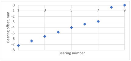
The Campbell diagram, as shown in
Figure 2a, is obtained using the first model. It gives information that the critical speed, excited with the 5th harmonic, is to be expected at 45 rpm. Therefore, BSR can be defined as the range between 40 and 51 rpm. The 1st torsional mode shape can be seen in
Figure 2b. This mode is excited with the 5th harmonic during the starting and stopping of the propulsion system when passing through the BSR.
2.2. Hull Deformation Influence on Propulsion Shaft
In the vast majority of cases, the influence of bending on the fatigue life is neglected. The works of Murawski [
6] and Seo et al. [
5] indicate that different design conditions of the ship’s hull have an influence on the propulsion shaft deflection curve.
One of the aims of this paper is to examine whether it is justified to ignore the impact of bending on the service life as often described by classification societies such as DNV [
4].
In the literature addressing the impact of hull deformation on the alignment of the ship’s propulsion shaft, some works focus on hull loading conditions. Other works analyze the impact of weather conditions, primarily considering the amplitude and frequency of waves encountered by the ship. The structure and purpose of the ship, such as tankers, bulk carriers, and container ships, also have a significant influence.
To analyze the influence of bending vibrations in the propulsion shaft on the assessment of fatigue life dominated by torsional vibrations, an additional static bending analysis was performed.
It is assumed that the lateral deflections of the shaft are small, justifying a separate, uncoupled analysis of torsional vibrations and a static analysis of the bending deformation of the propulsion shaft.
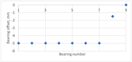
According to American Bureau of Shipping (ABS) [
13], the impact of hull girder deformation on shaft line alignment varies significantly across different ship categories, such as tankers, bulk carriers, and container ships. The ship’s size and the stiffness ratio between the shafting and the hull girder also play a crucial role. Therefore, four bearing offset cases described in the literature [
5,
6,
8,
17], were selected and adapted for a 20,000 DWT ship,
Table 4. These configurations represent the final outcomes of the applied shaft alignment methodology, considering the influence of the ship’s hull loading conditions (ballast or loaded). It is important to note that the actual bearing offset achieved is a result of the classification societies’ requirements, established shipyard practices, and alignment optimization based on the ship’s most common operational loading condition.
A static analysis was performed in Ansys Mechanical 2024R2. The model consisted of 27 beam elements. Bearing offsets were defined using the Ansys displacement boundary condition, while standard gravity was applied to the beams and additionally added point/lumped masses.
The results are given as shaft deflection curves and bending moment charts, as can be seen in
Figure 3. The black triangles in
Figure 3 represent the positions of the radial bearings. The propeller is located on the far right side, and the propulsion system has only one stern tube bearing and one intermediate bearing. The propeller and intermediate shaft are each divided into 5 beam finite elements. From
Figure 3b, it is evident that the intermediate shaft experiences the highest stress due to the bending moment in loading condition LC1, ranging from −62.32 to 69.56 kNm. Therefore, the value of 69.56 kNm is taken as the reference bending moment in the following analysis.
2.3. Low- and High-Cycle Fatigue of Intermediate Shaft
The DNV class guideline [
4] distinguishes 4 cases of loading of the thrust shaft of large ships. Case A refers to the change in load from zero to full load and back to zero, i.e., low-cycle fatigue (LCF). It is expected that the thrust shaft should withstand
to
cycles during operation. Case B is designed to prevent fatigue failure, caused by cyclic stresses during continuous operation associated with the total number of revolutions of the propeller shaft throughout the life of the ship. This defines the HCF criterion with about
cycles. Case C covers normal transient regimes that are not covered by case A because more than
cycles are expected. Case D describes extreme situations where a large positive torque is followed by a large negative torque, the so-called “crash stop” maneuvers. These torque reversals are assumed to occur much less than
times.
In this study, a quenched and tempered alloyed steel 34CrNiMo6 +QT is selected, with a chemical composition according to references [
18,
19,
20,
21] as given in
Table 5, and monotonic mechanical properties provided in
Table 6.
If the minimum strength values shown in
Table 6 are taken into account, then, according to [
22], 34CrNiMo6 alloyed steel can be characterized as a steel grade with a maximum tensile strength of
MPa and a yield strength of
MPa.
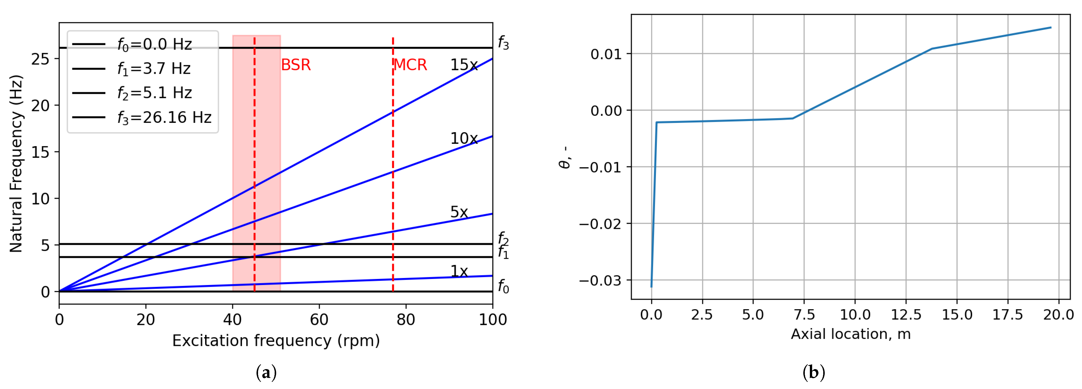
It is assumed that the intermediate shaft has a 410 mm diameter shaft with a flange fillet of multi-radii design as can be seen in
Figure 4. Surface roughness in flange fillet,
= 1.6 μm (arithmetical mean deviation of the profile), i.e.,
= 9.6 μm (maximum height of the profile—peak to valley) according to DNV [
4].
2.3.1. Low-Cycle Fatigue
Although the commonly used equation that describes the low-cycle fatigue behavior is the Coffin–Manson relation [
23], here, an empirical approach according to DNV [
4] is applied. Based on experience, it is known that axial stresses in direct coupled propulsion plants can generally be neglected. In this case of loading, it is also allowed to ignore bending stresses. Repetitive nominal peak torsional stress should meet the following condition:
where
is the nominal torsional stress,
is the steady-state vibratory torsional stress,
is the yield strength,
is a safety factor, and
is a component influence factor. Torque at maximum continuous rating (MCR)—
, as given in
Table 1, can be estimated as
where
is the max. continuous speed. Furthermore, the nominal torsional stress is determined as follows:
There are two possible maximum values of :
The empirical formula for the component influence factor for LCF takes into account the difference in the fatigue strength of the actual shaft component and a polished plain test specimen push–pull-loaded:
For multiradii transitions of the flange, , which gives and an actual safety factor of .
2.3.2. High-Cycle Fatigue
According to [
4,
24], torsion is also dominant in high-cycle fatigue, but bending can contribute, to a certain extent, to a reduction in service life. In this case, as explained in [
4], an HCF criterion
must be fulfilled, where
is the nominal vibratory torsional stress for continuous operation,
is the high cycle torsional fatigue strength,
is the nominal reversed bending stress amplitude,
is the high-cycle bending fatigue strength, and
is required safety factor. Torsional and bending fatigue strength for ordinary steels can be calculated:
where
is the nominal mean torsional stress at any load, and
,
and
are component influence factors for HCF for torsion and bending:
The first term in
and
denotes the notch influence term for HCF, the second term refers to the size (statistical) influence term for HCF, and the third denotes the surface condition influence term for HCF. For the given data,
,
,
, and
. If bending can be neglected, then the second term in Equation (
5) is eliminated, and the permissible torsional vibratory stress as a function of shaft speed can be expressed as:
If the bending is not negligible, then, from Equation (
5), assuming that the bending of the marine propulsion shafting is static and independent of the rotational speed, the allowable high-cycle stress, considering the influence of bending, can be obtained:
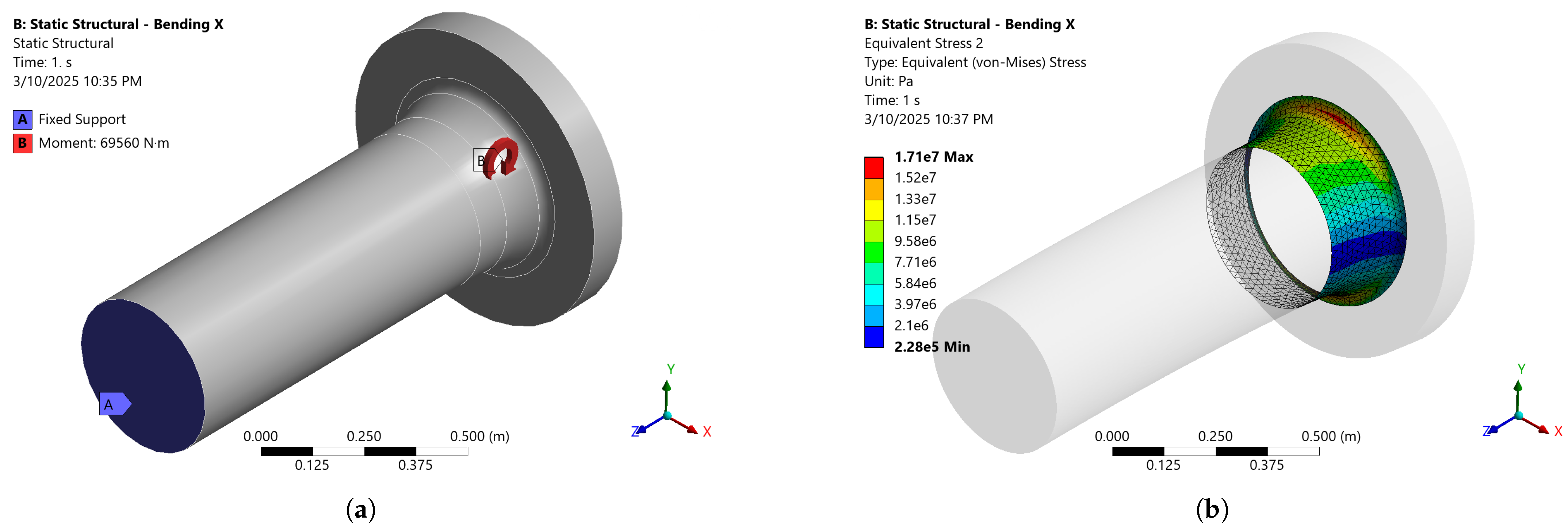
Considering the worst-case scenario of shaft alignment from
Section 2.2, a static bending moment of 69.56 kNm is identified as acting on the intermediate shaft. Due to shaft rotation, this induces dynamic bending cycles. The maximum equivalent stress of 17.1 MPa is observed at the flange fillet, as shown in
Figure 5b. Taking into account the obtained value of the stress due to static bending, the allowable intermediate shaft stress due to torsional and bending vibrations is obtained in the form:
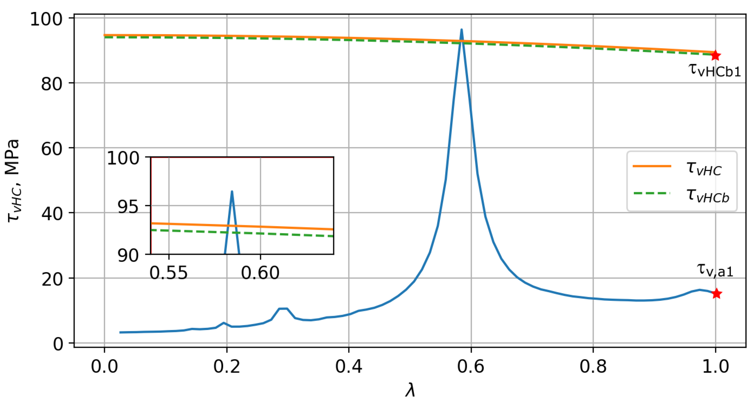
The differences between the permissible torsional stress limits for continuous operation for the case without and with bending stresses can be seen in
Figure 6. Here, a safety factor of torsional vibration stresses can be defined with respect to stress limits for steady-state operation in the regime above the BSR:
where
is the permissible torsional stress limit for continuous operation with bending stress influence for a specific
ratio and
is the calculated torsional stress amplitude for a specific
value. The values of
and
can, for a specific
value, be easily read from
Figure 6.
2.4. Biaxial High-Cycle Fatigue Assessment of Intermediate Shaft
An approach to solving high-cycle fatigue of the intermediate shaft based on an FE model is presented here. According to [
25], the multi-axial loading is basically divided into proportional and non-proportional. Non-proportional loading, although potentially offering a better estimate of fatigue life, faces three problems: First, strain hardening occurs in some materials. The second problem is the difficulty with counting cycles, and the third issue relates to the interpretation of damage parameters. Therefore, the proportional load approach will be applied in this work. Lee et al. [
26] states that fatigue damage largely depends on the applied stress amplitude or the applied stress range. As a secondary effect, the influence of mean stress is mentioned. There are several models of mean stress influence, of which the most recently used ones are [
27,
28] modified Goodman, Morrow, and Smith Watson Topper (SWT). In the considered case, biaxial cyclic torsion and bending with steady torsional loading are present. According to [
25], the torsional mean (steady-state) stress has no effect on fatigue as long as the maximum shear stress remains below the material yield strength.
Here, the equivalent von Mises stress (VM) approach will be applied [
29,
30], which predicts that fatigue initiation will occur if:
where
is the mean stress sensitivity factor,
is the fully reversed fatigue limit for normal stress, and
and
are the von Mises mean and amplitude stress:
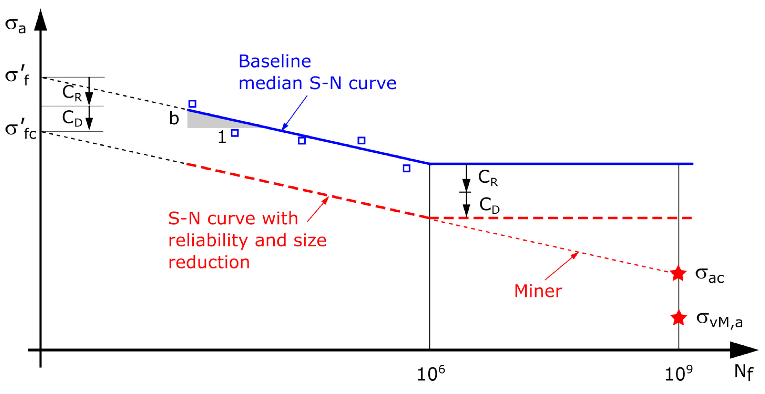
Although the references [
26,
29] list a whole series of coefficients that reduce the baseline
S-N curve defined by Basquin relation,
which refers to mirror-polished and notch-free conditions, here it is estimated that it is enough to take the reliability factor
and the size factor
[
31,
32], as can be seen in
Figure 7.
Given that the median curve corresponds to a 50% probability of survival, and considering the expected service life of the ship and its propulsion system to be 20–30 years, a higher reliability level of 0.999 is assumed. According to [
26], this corresponds to a reliability factor of
.
S-N curve is obtained by testing small specimens of diameter from 7.5 to 10 mm. The considered intermediate shaft has a diameter of 410 mm, so we can expect a certain decrease in physical properties with increasing dimensions. According to [
29], the
size correction factor for steels is calculated as:
where
and
are constants.
, for forging steel, which is quenched and tempered, is equal to 0.2 and
= 250 mm. This gives the value
= 0.957. Finally, the safety factor for the maximum equivalent stress
can be defined with respect to the corrected
S-N curve:
The values of
and
can be easily identified from
Figure 7.
3. Results and Discussion
In
Section 2 of this paper, the methodology used to assess the fatigue of the intermediate shaft in a marine propulsion system due to torsional and bending vibrations was presented. As previously mentioned, bending vibrations have no impact on LCF, so the focus here is on HCF. The DNV approach [
4], as described in
Section 2.3.2, ensures the required safety factor for high-cycle fatigue life. This implies that during the ship’s operational lifetime, the shaft will accumulate more than
cycles, typically ranging between
and
. Therefore, the safety factor at a lifetime of
cycles will serve as the primary parameter for comparison.
It is important to note that one revolution of the shaft corresponds to one bending cycle, while five torsional cycles occur simultaneously—one for each expansion stroke of the engine’s five cylinders. This means that within one combined torsion–flexion cycle, four additional torsional cycles occur, each with a significantly smaller bending influence.
Although [
33] recommends using the
S-N curve variant with a more gradual slope (twice as gentle) beyond
cycles, ref. [
29] suggests that for components subjected to variable amplitude loading, it is acceptable to assume a constant “Miner” slope. The input data for the considered cases are summarized in
Table 7.
The first row in
Table 7 represents the upper limit of the BSR, the second row corresponds to a potential slow steaming condition, the third and fourth rows reflect continuous operation, and the fifth row represents the MCR conditions.
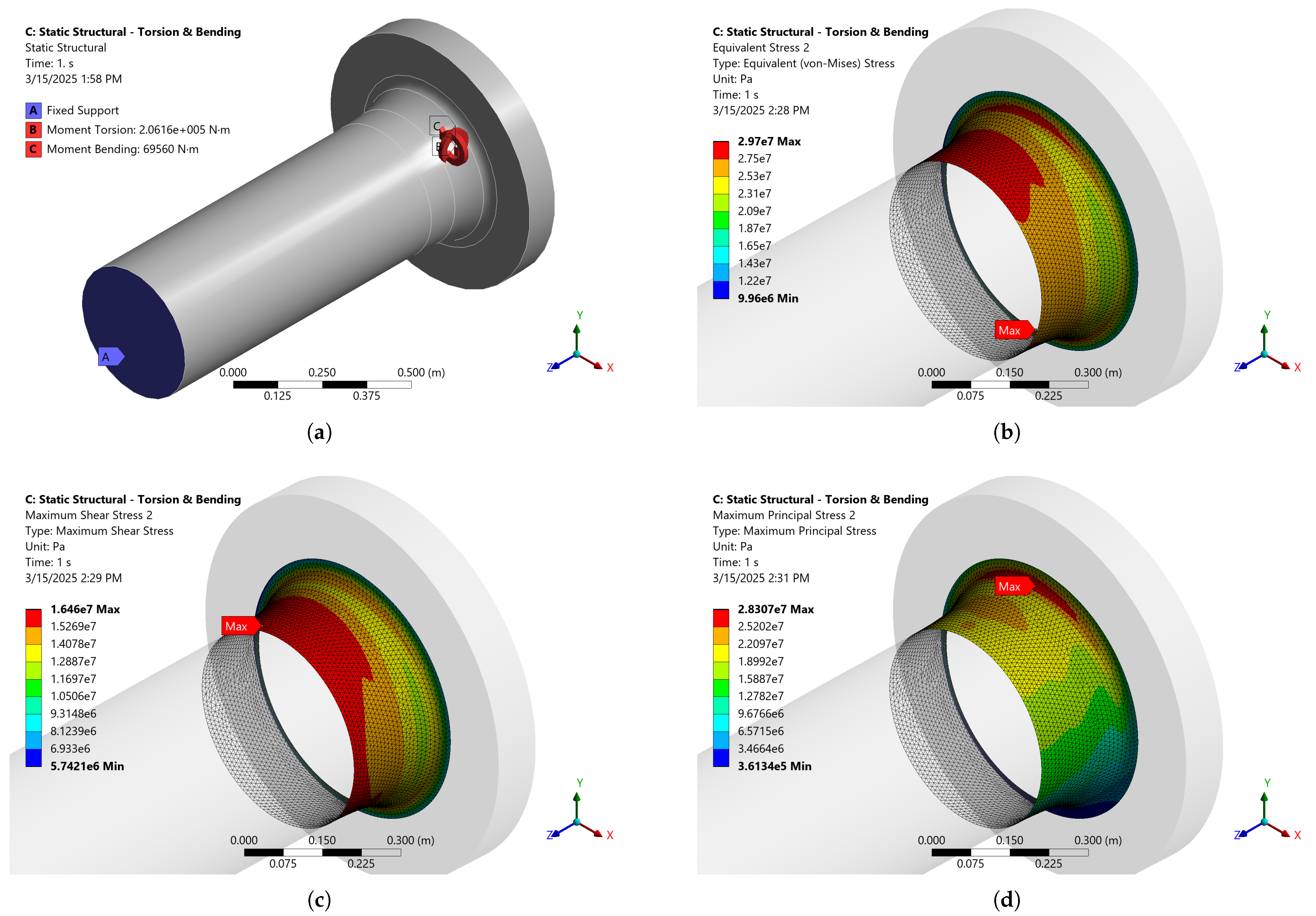
All structural finite element (FE) simulations were conducted in ANSYS 2024R2. The simulation shown in
Figure 5 consists of 319,793 nodes and 228,275 Tet10 elements. To perform a convergence test, the mesh density was increased to 2,503,106 nodes and 1,830,296 Tet10 elements, as illustrated in
Figure 8. A comparison of equivalent stresses due to a pure bending moment around the
X-axis reveals a slight increase from 17.1 MPa to 17.6 MPa, as seen in
Figure 5 and
Figure 8, representing a percentage increase of 2.92%. Although this increase is minor, all subsequent simulations will be performed using the denser FE mesh.
In addition to equivalent von Mises stress, the maximum shear and maximum principal stresses are also shown in
Figure 8. The results indicate that the highest stress concentrations occur in the same two zones of the flange fillet, symmetrically mirrored with respect to the neutral
X-Z plane. Notably, the maximum shear stress (9.9 MPa) is significant, while the maximum principal stress (19.95 MPa) is slightly higher than the equivalent stress (17.6 MPa).
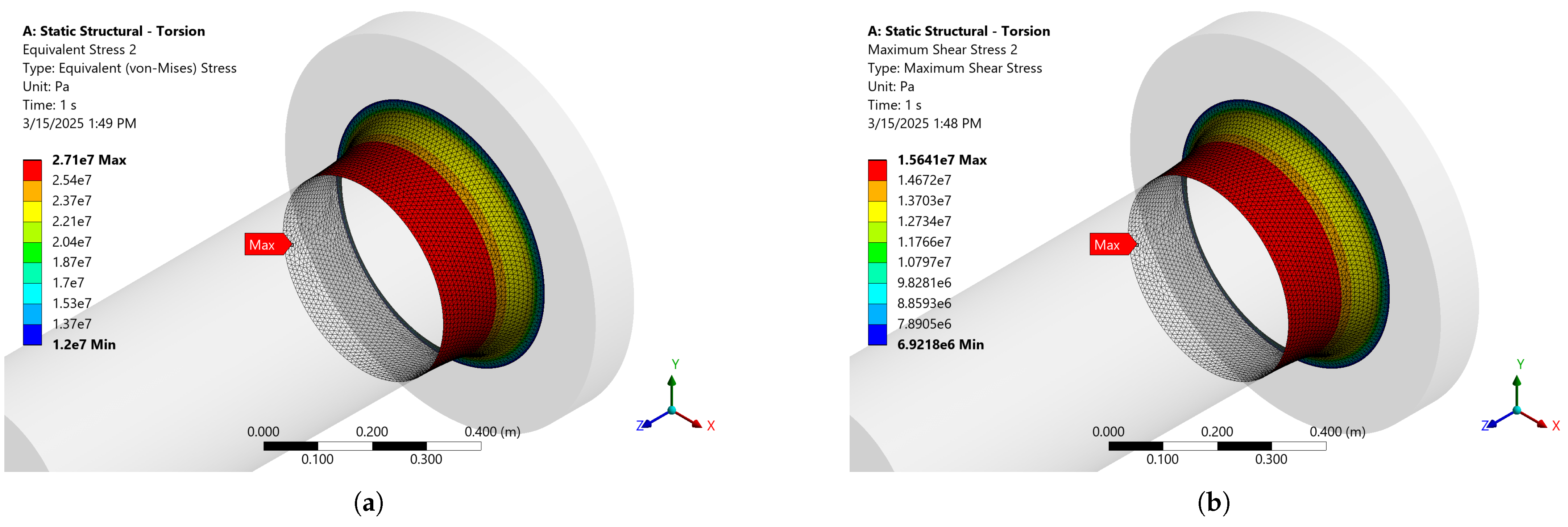
Figure 9 illustrates the stress response due to the torsional amplitude moment under MCR conditions, as specified in
Table 7. As expected, the stresses in
Figure 9 are symmetrical with respect to the
Z-axis and increase as the flange fillet diameter decreases. A proportional combination of torsional and flexural cycles determines the overall stress response, as shown in
Figure 10. For the given analysis conditions, it is evident that the equivalent stress in the combined torsional–bending loading case increased slightly (29.7 MPa) compared to the torsional loading case (27.1 MPa). More importantly, the influence of bending led to an irregular stress gradient that may favor the formation of an initial crack. In
Figure 10, it can also be seen that for the case of biaxial loading, the equivalent stress is still the highest in intensity and more clearly indicates the critical position in relation to the maximum shear and maximum principal stress. The safety factors for both approaches, DNV and the proposed approach according to
Section 2.4, are given in
Table 8. The safety factor described by Equation (
13) assumes a lifetime of
cycles, while the stress limit curve changes depending on the speed of rotation. At the same time, the safety factor, as described by Equation (
21), is calculated exactly for a lifetime of
cycles, while the equivalent stress state is calculated for the corresponding speed of rotation of the intermediate shaft.
Although the safety factors described by Equations (
13) and (
21) are defined in different domains—speed and lifetime—a noticeable similarity can be seen in
Table 8. It could even be said that the proposed safety factor for the coupled torsion–bending cycle is excessively small because such a significantly critical cycle occurs once in five cycles. Knowing that the DNV approach negligibly lowers, by less than 1 MPa, the allowable stress limit for the case with the torsional–flexural cycle compared to the case with torsional cyclic loading only, one can see a good agreement of the safety factor with the proposed approach that includes only torsion. In general, it can be concluded that for the given conditions, the impact of bending on the life of the intermediate shaft due to HCF is relatively small.
4. Conclusions
This study investigated the influence of bending vibrations on the fatigue life assessment of an intermediate shaft in a marine propulsion system, which is traditionally dominated by torsional vibrations. A detailed finite element (FE) analysis was conducted, considering both torsional and flexural vibrations, to determine whether the common practice of neglecting bending effects in fatigue life predictions is justified.
The analysis revealed that while torsional stresses remain the dominant factor in high-cycle fatigue calculations, the contribution of bending moments, particularly under worst-case shaft alignment conditions, results in a slight increase in stress levels. However, the overall influence of bending on fatigue life remains relatively small. The safety factors calculated using the proposed approach closely align with those obtained through the DNV method, reinforcing the validity of existing classification society guidelines.
Although bending-induced stress variations may contribute to localized stress concentrations and potential crack initiation sites, the magnitude of these effects appears minor compared to torsional loading. Consequently, for practical applications, the simplified approach of considering only torsional stresses for HCF life predictions remains reasonable. Nevertheless, for ships operating under extreme alignment deviations or in harsh environmental conditions, further investigation into the long-term impact of bending vibrations may be warranted.
Future work could explore dynamic bending effects in greater depth, incorporating more complex loading scenarios, transient conditions, and non-proportional fatigue damage models to refine fatigue life predictions for marine propulsion shafts.


