1. Introduction
As one of the earliest kinds of hydraulic pump, the reciprocating pump is a conveying machinery that directly provides energy to liquids in the form of pressure energy through the reciprocating motion of the piston. And using a tubular linear oscillating motor (TLOM) to directly drive the plunger for reciprocating oscillation motion could basically reduce the energy loss caused by transfer motion, which provides a new idea for the development of reciprocating pumps. At present, most applications of TLOM reciprocating pumps are refrigeration compressors [
1,
2,
3] or small high-precision pumps as artificial hearts [
4], while researchers have used it as a power source for electric hydrostatic actuators (EHAs) [
5,
6].
Research on linear motor reciprocating pumps can roughly be divided into two categories based on the different linear motors. One type is driven by a permanent magnet synchronous linear motor, and research focuses mainly on the impact of closed-loop control strategies for linear motor motion [
7,
8,
9], as well as the influences of motion path planning on the output performance of linear motor reciprocating pumps [
10]. Another type is driven by TLOM, which focuses on the different hydraulic flow distribution methods [
11] and structure designs of check valves [
12,
13,
14] for high-frequency reciprocating pumps. However, the largest problem with existing research models is that the linear motor system and hydraulic pump system were divided into two independent parts for analysis and research due to model simplification considerations. For example, when studying hydraulic pump systems, the TLOM system was simplified as a module with regular electromagnetic force output or displacement output, which caused a certain degree of distortion compared to actual working conditions.
In this article, a new reciprocating pump system based on TLOM for direct drive was proposed according to the typical structures and principles of permanent magnet synchronous linear motors and reciprocating pumps [
15,
16,
17,
18]. A mechanical-hydraulic-load coupling model was established based on the dynamic characteristic model of TLOM and the load model of the hydraulic pump system, based on which the dynamic characteristics of a multi-unit linear motor reciprocating pump and its output performance under different input signal parameters, and was studied in detail. Furthermore, a prototype experiment was designed to verify the effectiveness of the simulation model through experimental verification.
2. The Operating Principle of Reciprocating Pump Based on TLOM
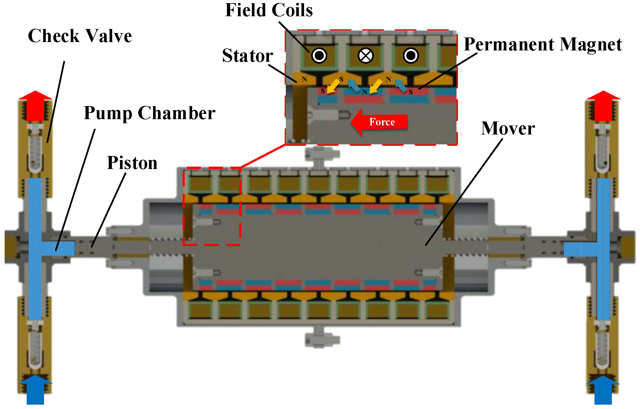
The TLOM is a new type of electromagnetic direct drive device that has emerged in recent years, which can directly convert input electrical energy into linear reciprocating oscillation motion without the need for any intermediate transmission mechanism. Indeed, the reciprocating pumps of TLOM are usually designed with a symmetrical structure to ensure stable operation. This means that all parts inside were axisymmetric to directly drive two sets of symmetrically arranged piston components, thus achieving relatively stable periodic reciprocating motion.
The structure of the reciprocating pump based on the TLOM of this article is shown in
Figure 1, which consists of a TLOM and two sets of symmetrically arranged piston components. The plunger is composed of the mover of TLOM and two pistons inside the pump chambers, which undergoes periodic reciprocating motion driven by a TLOM during working operation, with oil sucking and draining in the left and right pump chambers.
The control signal of TLOM is usually a periodic voltage excitation signal; thus, the amplitude and frequency of the plunger could be controlled by different parameters of the signal carrier, such as the type, frequency, and phase angle, which also means the digital control of displacement of the linear motor reciprocating pump. In addition, multiple linear motor reciprocating pumps can be connected in parallel to achieve a larger output flow, and smaller output flow fluctuations benefit from the modular design, with the adjustable parameters of each unit pump.
3. Establishment of Mechanical-Hydraulic-Load Coupling Model
The reciprocating pump system based on TLOM is a coupled connection between the motor system and the hydraulic system; therefore, it is necessary to establish a parameterized mechanical-hydraulic-load coupling model for detailed research. The AMEsim-Simulink co-simulation method was adopted in this article, the dynamic characteristic model of TLOM was established in the software of MATLAB/Simulink R2016b, and the hydraulic pump model was established in AMEsimV2019.1 according to the structure of the reciprocating pump, with a data exchange interface between the two models for the co-simulation of the mechanical-hydraulic-load coupling model.
3.1. The Dynamic Characteristic Model of TLOM
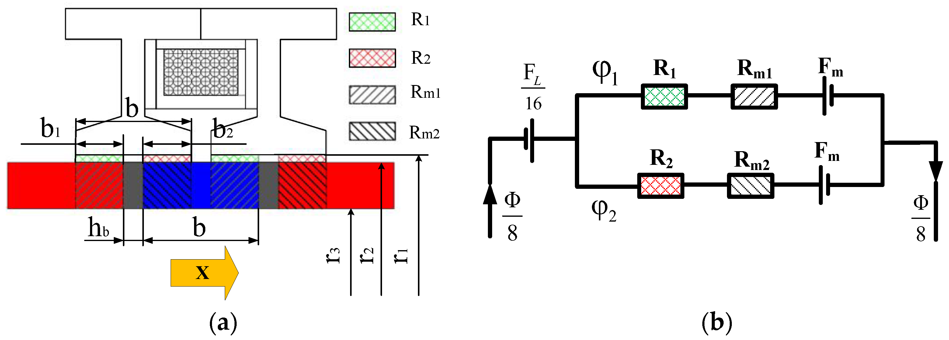
Due to the array structure of TLOM, the magnetic circuit of a single excitation coil was analyzed using the equivalent magnetic circuit method [
19,
20]. It could be simplified as shown in
Figure 2a, and the equivalent magnetic circuit is shown in
Figure 2b.
It was assumed that the effects of core hysteresis, eddy current loss, magnetic resistance, air gap leakage, and temperature changes on permanent magnet materials are negligible. According to the equivalent magnetic circuit of the coil, it could be described by Equation (1):
where
φ is the magnetic flux generated by energizing a single-turn excitation coil;
R1 and
R2 are the air gap reluctance between the two stator poles and the mover, respectively;
Rm1 and
Rm2 are the magnetic resistances of permanent magnets;
FL is the magnetic electromotive force generated by energizing the excitation coil; and
Fm is the magnetic electromotive force generated by a single permanent magnet tile.
From Equation (1), the magnetic flux of a single-turn coil (
φ) can be obtained as
And the stator flux linkage of TLOM is
where
δ is the thickness of the air gap;
S is the air gap cross-sectional area;
b′ is the relative size of magnetic poles;
Sm is the section area of the permanent magnet;
μr is relative permeability, which could be 1.02~1.08 for a Nd-Fe-B permanent magnet;
i is the instantaneous current inside the coil; and
x is the linear displacement of the plunger.
The electromagnetic force can be calculated from the magnetic energy of the motor based on the principle of virtual work, which is given by Equations (4)
–(7):
According to the control principle of TLOM, electromagnetic force would be generated to drive the permanent magnet mover to oscillate back and forth when inputting single-phase alternating current; thus, the coil voltage balance equation is given in the following form [
21]:
Based on the electromagnetic force equation from Equation (7), and voltage balance equation from Equation (8), the dynamic characteristic model of TLOM could be built, and the parameters of the model are provided in
Table 1.
3.2. The Hydraulic Model of Reciprocating Pump
According to the structure and working principle of a linear motor reciprocating pump, it mainly consists of a piston, pump chamber, reset spring, and flow distribution one-way valve. To control the suction and discharge of liquid in the plunger chamber, the two pump chambers each have a pair of one-way valves with opposite conduction directions to achieve flow distribution. And it was simplified as a single-degree-of-freedom mass–spring–damping system to analyze its dynamic characteristics due to its symmetrical structure. The inertia force of the system must be considered; accordingly, the force balance equation on a mover of TLOM is written as
where
m is the mass of the mover,
c is the friction damping coefficient, and
k is the spring stiffness.
Combined with Equations (7)–(9), the operating equation system of the reciprocating pump based on TLOM is reported as
Assuming input voltage
u(
t) = Asin
ωt, eliminate the intermediate variable current
i and set the load to 0; the forced vibration amplitude of the single-degree-of-freedom system under no-load conditions is calculated as
And the theoretical average flow rate of a reciprocating pump with two cylinders is
where
D0 is the piston diameter,
X0 is the reciprocating stroke of the piston, and
f is the frequency of reciprocating movement.
The parameters of the reciprocating pump are provided in
Table 2 as follows.
3.3. Dynamic Characteristic Analysis of Mechanical-Hydraulic-Load Coupling Model
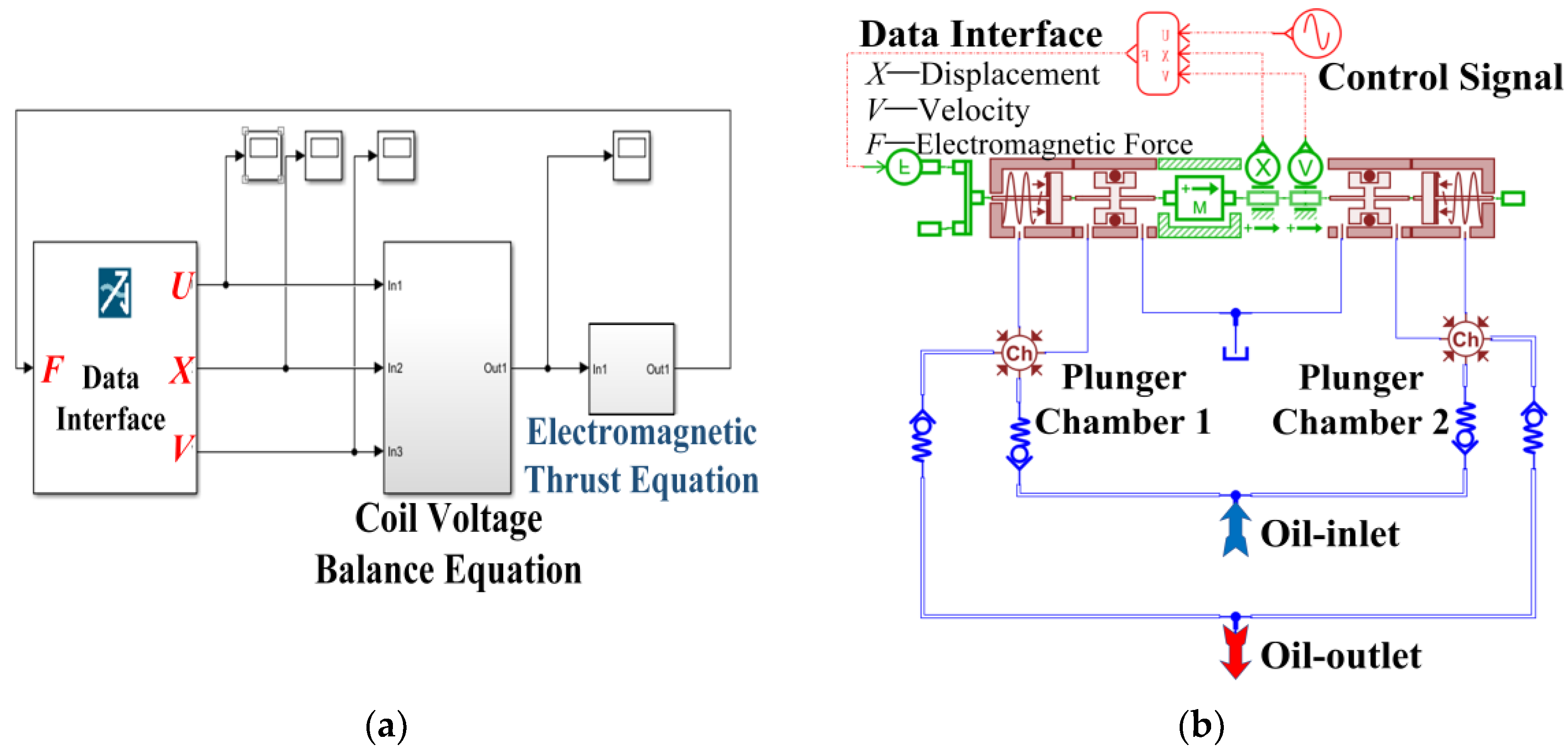
According to the operating equation system of the reciprocating pump based on TLOM (Equation (10)), the dynamic characteristics model of TLOM could be established in MATLAB/Simulink R2016b environment as shown in
Figure 3a. Otherwise, based on the structure and working principle of the reciprocating pump, the hydraulic model was established in software of AMEsimV2019.1 as shown in
Figure 3b. The hydraulic model of a reciprocating pump was mainly composed of pistons with reset springs, plunger chambers, and check valves, which are symmetrically arranged. There are a pair of check valves with opposite directions in the left and right pump chambers, which can control the liquid suction and discharge of the plunger chamber during the reciprocating motion of TLOM. And the leakage mainly occurs in the clearance of plunger pairs.
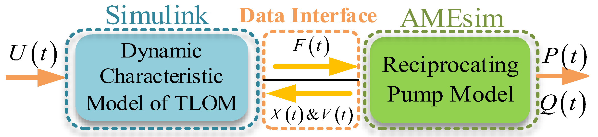
The working principle and data exchange path of the mechanical-hydraulic-load coupling model are shown in
Figure 4, and the data such as control signals, displacement, and velocity were transmitted through a data interface with an exchange frequency of 10 kHz.
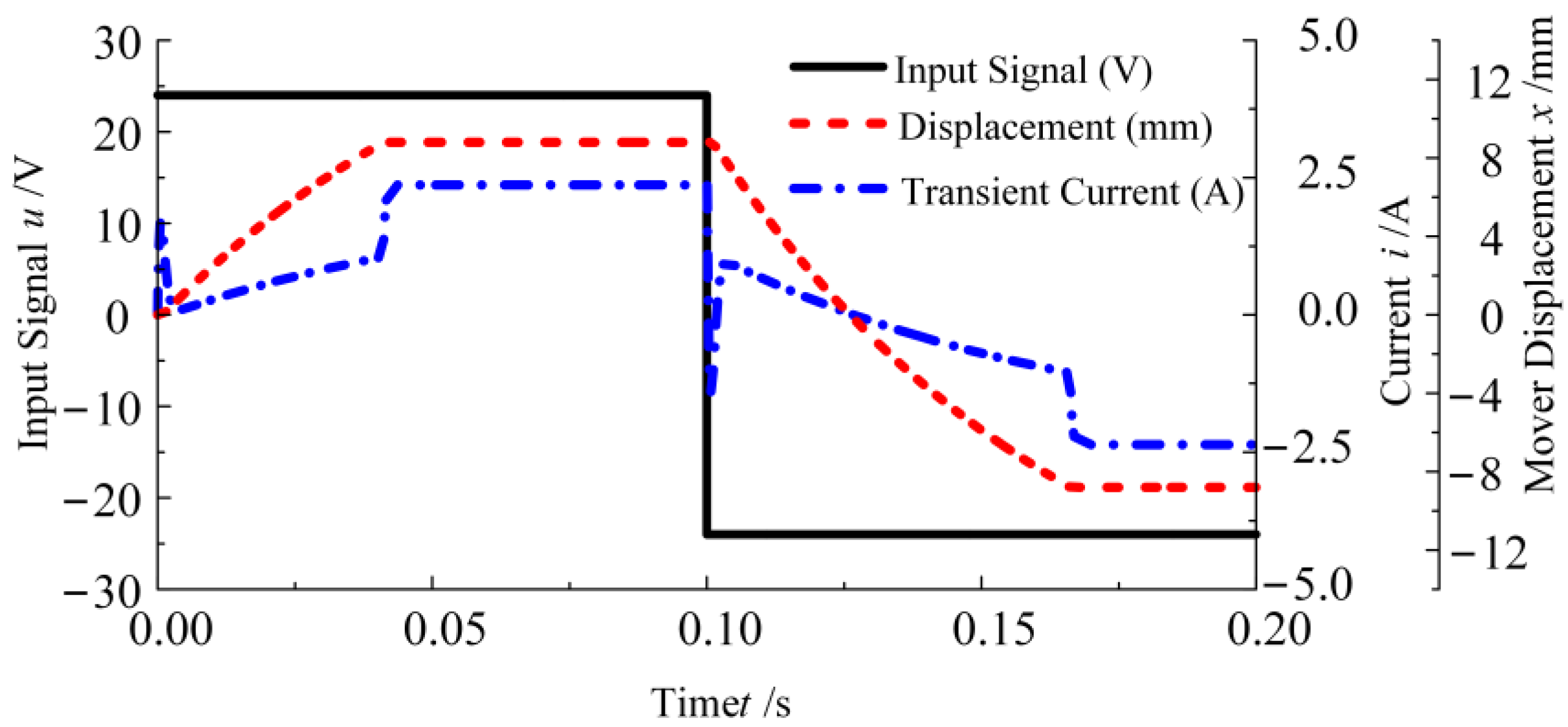
Based on the mechanical-hydraulic-load coupling model of the reciprocating pump, the input signal is set as a 24 V square wave voltage signal with a frequency of 5 Hz. And the dynamic characteristic of TLOM under hydraulic load inside one oscillation period is shown in
Figure 5, as well as the hydraulic output of the reciprocating pump provided in
Figure 6.
From
Figure 5, there are two parts to the action delay of the linear motor reciprocating pump. One is the electrical delay caused by the inductive effect of the coil, resulting in the fluctuation of electromagnetic thrust. Another is the mechanical delay brought by the spring resistance and hydraulic resistance.
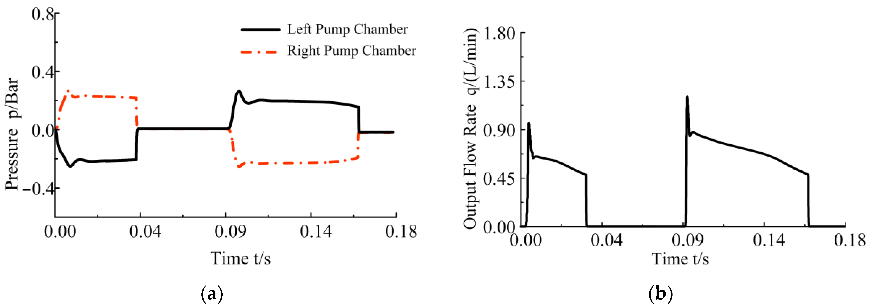
According to the dynamic characteristic of the mechanical-hydraulic-load coupling model shown above, the left and right pump chambers would always be in the stage of one oil suction and one oil discharge for the reciprocating oscillation motion of the plunger (as shown in
Figure 6a). For this reason, the hydraulic flow has an interruption rather than continuous output in the alternating gap, as shown in
Figure 6b. It is hard to take a single linear motor reciprocating pump as an independent hydraulic oil power source from a practical perspective. Nevertheless, the parallel connection of multiple linear motor pumps and control of the linear motor at the same motion frequency and a certain phase difference would achieve continuous output. And it must be noted that the fluctuations of pressure and flow were caused by the hysteresis effect of the spring system at the moment when the check valve opens.
3.4. Experiment Test of the Reciprocating Pump of TLOM
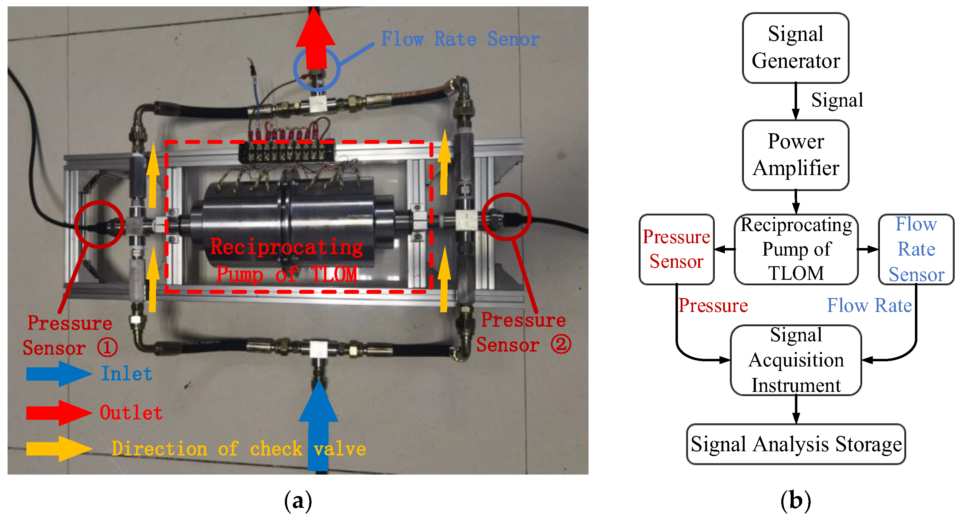
To confirm the effectiveness of the mechanical-hydraulic-load coupling model built above, a prototype of a reciprocating pump of TLOM was built for output performance experimental testing, shown in
Figure 7. The pressure sensor used in the experiment is a flat film ceramic hydraulic pressure sensor with a range of 10 Bar and a measurement accuracy of about 1.5%. The experimental data were collected using a 24-bit high-precision acquisition instrument with a sampling accuracy of 1 mV and a sampling frequency of 512 Hz. Before the experiment began, the hydraulic pipeline was filled with oil, and the sensor values were zeroed. Then, sine-wave voltage signals were generated through a function signal generator to control the prototype to complete ten reciprocating oscillations at a frequency of 1 Hz and real-time hydraulic sensor values were recorded for further analysis.
The comparison between the hydraulic output parameters of the prototype and the simulation model is shown in
Figure 8, which respectively shows the pressure and flow rate of a single chamber.
It must be noted that the opening pressure of the one-way valve used in both the simulation model and experiment was 0.2 Bar. According to the curves of pressure shown in
Figure 8a, the simulation results of the simulation are basically consistent with the experimental results. And the simulation of the mechanical-hydraulic-load coupling model accurately simulates the pressure fluctuation of the pump chamber at the moment when the one-way valve is opened, which was caused by the back pressure generated by the switching of the working states of the two one-way valves in the same pump chamber. Due to the accuracy of the pressure signal sensors and signal acquisition equipment used in the experiment, this part of the data is difficult to reflect in the curve obtained from the experiment. The comparison of hydraulic flow output curves shown in
Figure 8b is also similar, but due to the limited processing technology, the flow output of the prototype was slightly lower than the simulation data, which was caused by the leakage.
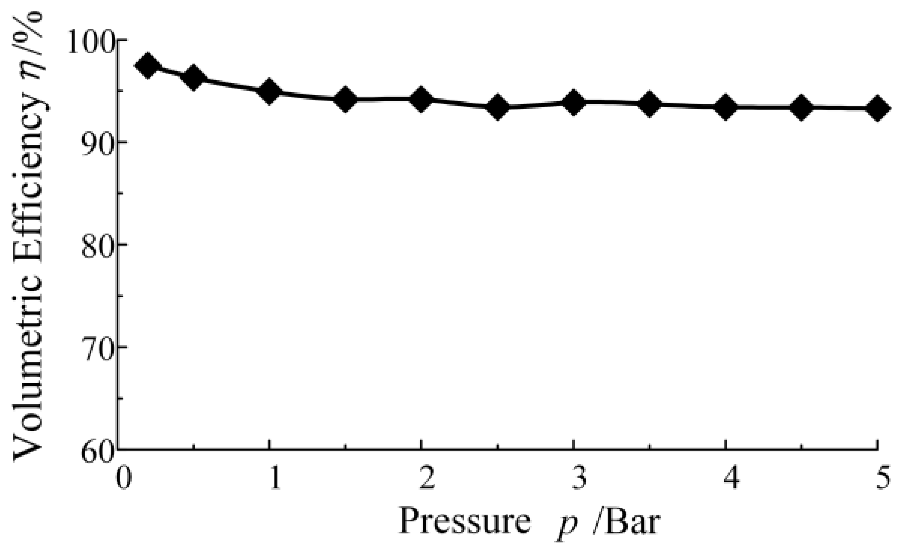
According to the hydraulic pressure and flow rate shown above, the volumetric efficiency of the hydraulic pump could be calculated as:
According to the above calculation method, the volumetric efficiency of the linear motor reciprocating pump system under the different load conditions could be tested and calculated, which is shown in
Figure 9. And the volumetric efficiency of the system is about 93.3~96.4%, decreased with increasing load, which is much higher than the gear pump and vane pump commonly used in the hydraulic system, and is close to the efficiency of the axial piston pump. The greater advantage of the linear motor reciprocating pump system is not only reflected in its high system efficiency, but also reflected in its ability to change the combination form according to the actual work demand and adopt intelligent control of TLOM to achieve precise control of hydraulic output.
The overall results of the simulation model are consistent with the experimental data of the prototype, which can prove the effectiveness of the mechanical-hydraulic-load coupling model.
4. Parallel Output Characteristics of Multi-Unit Linear Motor Reciprocating Pump Unit
To address the issue of discontinuous flow output mentioned above, a multi-unit reciprocating pump group can be used to work in parallel and collaboratively. This means that all oil suction ports of different pump units were connected to the oil tank, and all oil discharge ports were connected to the hydraulic load. Then, different pump groups were adjusted to input voltage excitation signals with the same frequency and a certain phase difference. In traditional hydraulic systems, there are also ways in which dual or even multiple pump groups work in parallel to reduce flow output pulsation. A pump group model with three linear motor reciprocating pump units was built to study the hydraulic output characteristics, which is shown in
Figure 10. The input signal was set as a sin-wave voltage signal of the same frequency and amplitude, with adjacent pump units maintaining a 120° signal phase difference, and a hydraulic load of 5 Bar.
Due to the inductive reactance effect of coils under periodic voltage signal, the self-induced electromotive force will be generated to hinder the change of coil current, thereby affecting the magnetic field energy storage of the coil and causing a change in the electromagnetic output force of TLOM. Therefore, the type, frequency, and phase angle of the alternating excitation voltage signal will have an impact on the performance of the reciprocating pump based on the TLOM.
4.1. Types of Signals
To explore the response characteristics of the simulation model of a multi-unit linear motor reciprocating pump to different waveform voltage signals, three common voltage signals were selected, namely a sawtooth wave signal, square wave signal, and sine wave signal. The frequency of the signal was set to 5 Hz and the load pressure to 5 Bar, and the displacement curve of the plunger is shown in
Figure 11.
The plunger keeps periodic oscillations under the excitation of three different signals. But the plunger is in an asymmetric oscillation motion state when the excitation voltage signal is a sawtooth wave, which not only leads to uneven output of the left and right pump chambers within the same motion cycle, but also easily damages the motor due to asymmetric oscillation. The sawtooth wave excitation signal is not suitable as a control signal for that reason.
The flow output curve of the pump was selected, and the flow pulsation rate was calculated to characterize the uniformity of the hydraulic pump flow output by using Equation (14).
where
qmax is the peak flow rate under a stable output state,
qmin is the flow valley under a stable output state, and
qavg is the average flow output.
By comparing the flow output curve of the pump shown in
Figure 12a,b, the average flow output under two different signals is 1.39 L/min to a sine wave signal and 1.54 L/min to a square wave signal. It is known that a pump can have a greater flow output under square wave signals. However, the flow pulsation rate for the square wave is about 48.3%, and for the sine wave is 13.1% according to the calculation result of Equation (16). It can be inferred that there is a larger flow pulsation rate for the square wave signal, which means a worse uniformity of the hydraulic pump flow output and the sine wave voltage signal is more suitable as a control signal carrier for that reason.
4.2. Phase Angle
For a multi-unit linear motor reciprocating pump, its flow output characteristics are quite similar to traditional axial piston pumps. And axial piston pumps can be seen as multiple linear motor reciprocating pump units connected in parallel, with adjacent unit input signals maintaining the same phase angle. In the design of traditional axial piston pumps, when the number of pistons is designed to be even, the instantaneous output peaks are easily superimposed, causing significant output flow pulsation. Owing to the independence of the constituent units of the linear motor pump group, the peaks and valleys in the flow output curve can be mutually compensated by adjusting the phase angle of the input signal, which can achieve the effect of reducing oil source flow pulsation. A similar method was also used to suppress flow output pulsation in traditional axial piston pumps, known as staggered parallel connection [
22].
In order to investigate the effect of different phase lag angles on the flow output pulsation of a multi-unit linear motor reciprocating pump group, a linear motor reciprocating pump with two units was taken for research. The flow output data of the pump unit obtained through analysis are shown in
Table 3, with a phase angle range of 15~165°.
According to
Table 3, less difference exists in the peak and average flow rates of the pump group corresponding to different phase lag angles, and the changes in flow pulsation rate are mainly caused by the valley value of the flow output. As the phase angle increases from 15° to 165°, the flow pulsation rate shows a trend of first decreasing and then increasing, and reaches its minimum value of about 29.9% when the phase angle is 90°.
Considering the pump group with an even number of parallel pump units as a staggered combination of multiple sets of double unit pump units and adopting a 90° phase angle inside each double unit pump group could be a great way to reduce the flow output pulsation of even-numbered parallel pump groups. Taking the pump group with six parallel pump units as an example, in the original parallel working scheme, the phase angle of adjacent linear motor pump units is 60°, and the signal phase angles of each unit with a staggered parallel scheme are shown in
Table 4.
The output flow curve of the linear motor pump group using different parallel schemes under a stable state is shown in
Figure 13. The flow output pulsation of the linear motor pump group using the staggered parallel connection scheme is about 3.12%, which is much smaller than that of the original parallel connection scheme of 11.27%. It is a significant decrease of about 72.3%.
5. Conclusions
To study the dynamic characteristics of a multi-unit linear motor reciprocating pump and its output performance under different input signal parameters, a mechanical-hydraulic-load coupling model was established based on the electromagnetic output model of TLOM and the load model of the hydraulic pump system, and a prototype experiment was designed to verify the effectiveness of the simulation model through experimental verification.
Several meaningful conclusions were drawn as follows:
The mechanical-hydraulic-load coupling model established in this paper can effectively present the output performance of the linear motor reciprocating pump in actual working conditions, which was verified by the prototype output performance experiment. And the volumetric efficiency of the system is about 93.3~96.4%, decreased with increasing load.
The type and phase angle of the control signal of the reciprocating pump based on TLOM have a significant impact on its output performance, and reasonable selection of various parameters can significantly improve its output performance. Overall, sine wave signals are most suitable as control signal carriers for linear motor reciprocating pumps with better output performance.
The staggered parallel connection scheme can effectively reduce the flow output pulsation of the reciprocating pump group with even units. For the pump group with six units, the fluctuation rate of flow output significantly decreased by about 72.3%.
Author Contributions
Conceptualization, J.X. and X.Y.; Data curation, X.Y.; Formal analysis, L.L.; Methodology, Z.W.; Software, Z.Q.; Validation, J.X., Z.W. and X.Y.; Writing—original draft, J.X.; Writing—review and editing, Z.W. All authors have read and agreed to the published version of the manuscript.
Funding
This research was funded by General Research Projects of Zhejiang Provincial Department of Education, grant number Y202455243, and Research Fund of School of Information Engineering, Hangzhou Dianzi University, grant number KYP0224002.
Data Availability Statement
The raw data supporting the conclusions of this article will be made available by the authors on request.
Conflicts of Interest
The authors declare no conflicts of interest.
Abbreviations
The following abbreviations are used in this manuscript:
| TLOM | Tubular linear oscillating motor |
| EHA | Electric hydrostatic actuators |
References
- Hwang, I.S.; Lee, Y.L. Study on performance change in a linear compressor considering refrigerant leakage through the suction valve clearance. J. Mech. Sci. Technol. 2019, 33, 2665–2670. [Google Scholar] [CrossRef]
- Bijanzad, A.; Hassan, A.; Lazoglu, I.; Kerpicci, H. Development of a new moving magnet linear compressor, part B: Performance analysis-science direct. Int. J. Refrig. 2020, 113, 94–102. [Google Scholar] [CrossRef]
- Chen, H.; Lv, Z.; Liu, X.; Chen, C. Static and dynamic characteristics of a novel moving magnet linear compressor. J. Mech. Sci. Technol. 2022, 36, 87–97. [Google Scholar] [CrossRef]
- Ji, J.H.; Yan, S.J.; Zhao, W.X.; Liu, G.H.; Zhu, X.Y. Minimization of Cogging Force in a Novel Linear Permanent-Magnet Motor for Artificial Hearts. IEEE Trans. Magn. 2013, 49, 3901–3904. [Google Scholar] [CrossRef]
- Liang, H.; Jiao, Z.; Yan, L.; Zhao, L.; Wu, S.; Li, Y. Design and analysis of a tubular linear oscillating motor for directly-driven EHA pump. Sens. Actuators A Phys. 2014, 210, 107–118. [Google Scholar] [CrossRef]
- Kano, Y.; Satou, K. Design and Experimental Verification of a High Force Density Tubular Permanent Magnet Linear Motor for Aerospace Application. SAE Int. J. Adv. Curr. Pract. Mobil. 2020, 2, 818–827. [Google Scholar] [CrossRef]
- Jiao, Z.X.; Cao, Y.; Yan, L.; Li, X.; Zhang, L.; Li, Y. Advancing motivation feedforward control of permanent magnetic linear oscillating synchronous motor for high tracking precision. Actuators 2021, 10, 128. [Google Scholar] [CrossRef]
- Lu, Y.; Tan, C.; Ge, W.; Li, B.; Lu, J. Improved Sliding Mode-Active Disturbance Rejection Control of Electromagnetic Linear Actuator for Direct-Drive System. Actuators 2021, 10, 138. [Google Scholar] [CrossRef]
- Wang, Z.; Hu, C.X.; Zhu, Y.; He, S.Q.; Yang, K.M.; Zhang, M. Neural network learning adaptive robust control of an industrial linear motor-driven stage with disturbance rejection ability. IEEE Trans. Ind. Inform. 2017, 13, 2172–2183. [Google Scholar] [CrossRef]
- Dong, W.T.; Nie, S.L. Research on motion planning of linear motor driven piston pump. China Mech. Eng. 2014, 25, 1080–1084. [Google Scholar]
- Li, X.L.; Jiao, Z.X.; Yan, L.; Cao, Y. Modeling and experimental study on a novel linear electromagnetic collaborative rectification pump. Sens. Actuators A Phys. 2020, 309, 111883. [Google Scholar] [CrossRef]
- Ye, Y.; Chen, J.; Ren, Y.J.; Feng, Z.H. Valve improvement for high flow rate piezoelectric pump with pdms film valves. Sens. Actuators A Phys. 2018, 283, 245–253. [Google Scholar] [CrossRef]
- Chaudhuri, A.; Yoo, J.; Wereley, N.M. Design, test and model of a hybrid magnetostrictive hydraulic actuator. Smart Mater. Struct. 2009, 18, 085019. [Google Scholar] [CrossRef]
- Sirohi, J.; Chopra, I. Design and Development of a High Pumping Frequency Piezoelectric-Hydraulic Hybrid Actuator. J. Intell. Mater. Syst. Struct. 2003, 14, 135–147. [Google Scholar] [CrossRef]
- Jiao, Z.X.; Wang, T.Y.; Yan, L. Design of a tubular linear oscillating motor with a novel compound halbach magnet array. IEEE/ASME Trans. Mechatron. 2017, 22, 498–508. [Google Scholar] [CrossRef]
- Shen, Y.; Zhu, Z.Q. Analysis of electromagnetic performance of halbach PM brushless machines having mixed grade and unequal height of magnets. IEEE Trans. Magn. 2013, 49, 1461. [Google Scholar] [CrossRef]
- Luo, X.S.; Zhang, C.; Wang, S.P.; Zio, E.; Wang, X.J. Modeling and analysis of mover gaps in tubular moving-magnet linear oscillating motors. Chin. J. Aeronaut. 2018, 31, 927–940. [Google Scholar] [CrossRef]
- Gidde, R.R.; Pawar, P.M.; Ronge, B.P.; Dhamgaye, V.P. Design optimization of an electromagnetic actuation based valveless micropump for drug delivery application. Microsyst. Technol. 2019, 25, 509–519. [Google Scholar] [CrossRef]
- Yu, W.B.; Yang, G.L.; Li, Z.X.; Wang, D.R.; Wang, X.Y. A tubular linear motor structure suitable for large thrust. J. Mech. Sci. Technol. 2021, 35, 4987–4995. [Google Scholar] [CrossRef]
- Hoshina, T.; Deng, M. A Nonlinear Control of Linear Slider Considering Position Dependence of Interlinkage Flux. Machines 2022, 10, 522. [Google Scholar] [CrossRef]
- Wang, T.Y.; Jiao, Z.X.; Yan, L. Underdamping characteristic analysis and dual-feedback control for flooded linear oscillating motor. In Proceedings of the 2016 IEEE Chinese Guidance, CGNCC, Nanjing, China, 12–14 August 2016; pp. 455–460. [Google Scholar] [CrossRef]
- Yu, L.J.; Wang, X.D.; Zhang, X.C. Control and simulation of flow pulsation in axial plunger pump. J. Xi’an Jiao Tong Univ. 2013, 47, 43–47. [Google Scholar] [CrossRef]
Figure 1.
Sectional view of reciprocating pump based on TLOM.
Figure 1.
Sectional view of reciprocating pump based on TLOM.
Figure 2.
Single coil magnetic circuit of TLOM. (a) Simplified analysis of magnetic circuit model; (b) equivalent magnetic circuit of coil of TLOM.
Figure 2.
Single coil magnetic circuit of TLOM. (a) Simplified analysis of magnetic circuit model; (b) equivalent magnetic circuit of coil of TLOM.
Figure 3.
Establishment of mechanical-hydraulic-load coupling model. (a) The dynamic characteristics model of TLOM; (b) hydraulic model of reciprocating pump.
Figure 3.
Establishment of mechanical-hydraulic-load coupling model. (a) The dynamic characteristics model of TLOM; (b) hydraulic model of reciprocating pump.
Figure 4.
The working principle of mechanical-hydraulic-load coupling model.
Figure 4.
The working principle of mechanical-hydraulic-load coupling model.
Figure 5.
Typical dynamic characteristics within one motion cycle.
Figure 5.
Typical dynamic characteristics within one motion cycle.
Figure 6.
Output of reciprocating pump based on TLOM. (a) Pressure of the chambers; (b) hydraulic flow output.
Figure 6.
Output of reciprocating pump based on TLOM. (a) Pressure of the chambers; (b) hydraulic flow output.
Figure 7.
The equipment of prototype output performance experiment. (a) Experimental setup for prototype; (b) experimental setup principle.
Figure 7.
The equipment of prototype output performance experiment. (a) Experimental setup for prototype; (b) experimental setup principle.
Figure 8.
Comparison of simulation and experimental data under 1 Hz frequency. (a) Pressure of the chambers; (b) hydraulic flow output.
Figure 8.
Comparison of simulation and experimental data under 1 Hz frequency. (a) Pressure of the chambers; (b) hydraulic flow output.
Figure 9.
Volumetric efficiency of the linear motor reciprocating pump system.
Figure 9.
Volumetric efficiency of the linear motor reciprocating pump system.
Figure 10.
The operating principle of parallel collaboration mode of multi-unit linear motor reciprocating pump.
Figure 10.
The operating principle of parallel collaboration mode of multi-unit linear motor reciprocating pump.
Figure 11.
Time-varying curve of plunger displacement under different excitation signals.
Figure 11.
Time-varying curve of plunger displacement under different excitation signals.
Figure 12.
Flow rate curve of pump under different input signals. (a) Sine wave signal; (b) square wave signal.
Figure 12.
Flow rate curve of pump under different input signals. (a) Sine wave signal; (b) square wave signal.
Figure 13.
Flow rate curve of pumps of different parallel connection schemes.
Figure 13.
Flow rate curve of pumps of different parallel connection schemes.
Table 1.
The dynamic characteristics parameters of TLOM.
Table 1.
The dynamic characteristics parameters of TLOM.
| Parameters | Symbols | Value |
|---|
| Number of coils | n | 9 |
| Turns | N | 280 |
| Air gap thickness | δ | 1 mm |
| Magnet thickness | hm | 6 × 10⁻³ m |
Table 2.
Hydraulic model parameters of reciprocating pump.
Table 2.
Hydraulic model parameters of reciprocating pump.
| Parameters | Symbols | Values |
|---|
| Density of oil | ρ | 850 kg/m3 |
| Bulk modulus of oil | E | 1700 Mpa |
| Piston diameter | D0 | 8 mm |
| Reciprocating stroke | X0 | ±8.8 mm |
| Spring stiffness | k | 15 N·mm−1 |
| Check valve open pressure | p | 0.2 Bar |
Table 3.
The flow rate output of different phase angles.
Table 3.
The flow rate output of different phase angles.
| Phase Angle β/° | qmax/L/min | qmin/L/min | qavg/L/min | σq/% |
|---|
| 15° | 1.64 | 0.12 | 0.84 | 180.95 |
| 30° | 1.59 | 0.42 | 0.89 | 131.46 |
| 45° | 1.53 | 0.58 | 0.94 | 101.06 |
| 60° | 1.45 | 0.62 | 1.15 | 72.17 |
| 75° | 1.36 | 0.73 | 1.24 | 50.81 |
| 90° | 1.11 | 0.82 | 0.97 | 29.90 |
| 105° | 1.35 | 0.75 | 1.17 | 51.28 |
| 120° | 1.48 | 0.66 | 1.11 | 73.87 |
| 135° | 1.55 | 0.56 | 0.96 | 103.13 |
| 150° | 1.57 | 0.39 | 0.92 | 128.26 |
| 165° | 1.68 | 0.09 | 0.89 | 178.65 |
Table 4.
The signal phase angles of different parallel connection schemes.
Table 4.
The signal phase angles of different parallel connection schemes.
| Unit | Parallel | Staggered Parallel |
|---|
| 1 | 0° | 0° | Dual Units I |
| 2 | 60° | 90° |
| 3 | 120° | 120° | Dual Units II |
| 4 | 180° | 210° |
| 5 | 240° | 240° | Dual Units III |
| 6 | 300° | 330° |
| Disclaimer/Publisher’s Note: The statements, opinions and data contained in all publications are solely those of the individual author(s) and contributor(s) and not of MDPI and/or the editor(s). MDPI and/or the editor(s) disclaim responsibility for any injury to people or property resulting from any ideas, methods, instructions or products referred to in the content. |
© 2025 by the authors. Licensee MDPI, Basel, Switzerland. This article is an open access article distributed under the terms and conditions of the Creative Commons Attribution (CC BY) license (https://creativecommons.org/licenses/by/4.0/).


