Article

Various Designs of Spoke-Type Permanent Magnet Motor for Performance Optimization

1
Faculty of Electrical Engineering, Goce Delcev University, 2000 Stip, North Macedonia
2
Faculty of Electrical Engineering and Information Technologies, Ss. Cyril and Methodius University, 1000 Skopje, North Macedonia
3
Faculty of Electrical Engineering and Information Technology, Slovak University of Technology in Bratislava, 841 04 Bratislava, Slovakia
4
Faculty of Computer Science and Engineering, Ss. Cyril and Methodius University, 1000 Skopje, North Macedonia
*
Author to whom correspondence should be addressed.
Machines 2025, 13(5), 375; https://doi.org/10.3390/machines13050375
Submission received: 14 March 2025 / Revised: 7 April 2025 / Accepted: 14 April 2025 / Published: 30 April 2025

Abstract

Obtaining an optimal motor design is not always a simple task, considering that it involves designing a model with many interrelated parameters, where each modification significantly affects the motor’s performance characteristics. This paper analyses numerous synchronous motor models with embedded magnets of spoke-type, obtained by varying several parameters (magnets and motor length, magnets width, and number of conductors per slot) within defined limits in a software module optimetric analysis. Each combination of these varied parameters results in a different motor model with corresponding performance characteristics. From the obtained models, the best solutions are identified, i.e., combinations of parameters that result in high efficiency while simultaneously minimizing the consumption of magnetic material and reducing cogging torque. The conducted analysis revealed that there is more than one model that can be considered as optimal, especially when considering multiple objectives, such as high efficiency, low magnetic material consumption, reduced dimensions, and low cogging torque. The application of optimetric analysis also enables the execution of a sensitivity analysis, examining the impact of each varied parameter on the corresponding objective function. The presented methodology offers the designer a range of solutions that can be identified as optimal, providing greater flexibility in the construction of appropriate prototypes.

1. Introduction

The advancement of material technology has significantly contributed to the development of synchronous motors, which have emerged as a superior alternative to induction squirrel cage motors that dominated the industry for decades. While three-phase squirrel cage motors are known for their simple design and robust operation, they have inherent drawbacks due to their operating principles, including lower efficiency, poor power factor, and high material consumption. Additionally, achieving higher efficiency with these motors requires increased size, yet their efficiency still remains lower compared to that of synchronous motors. Synchronous motors, on the other hand, are widely adopted across various industries due to their high efficiency, constant speed, and precise control [1]. They are commonly used in industrial applications such as compressors, pumps, fans, and conveyor systems, where maintaining a consistent speed is crucial. Another key application is in electric vehicles (EVs), where they serve as a core component of electric and hybrid drivetrains, offering superior energy efficiency and enhanced regenerative breaking. The motor designer often faces challenges in achieving the optimal design that meets specific operational requirements, such as high efficiency, while also minimizing production costs and material consumption. This task becomes even more challenging for synchronous motors with magnets in the rotor instead of windings, as rare earth magnets—commonly used in designs with embedded magnets in the rotor—are expensive and have limited availability. Motor design is a complex, multivariable problem where numerous parameters influence operating characteristics. Often, enhancing one characteristic may negatively impact another due to changes in one or more design parameters. Finding the optimal combination of these parameters can be a time-consuming process, and achieving the best balance between cost and performance is not always possible. The development of software tools enables the calculation of numerous motor models by defining variation boundaries for selected parameters while simultaneously computing key operating characteristics. The choice of parameters to vary and the performance characteristics to evaluate is guided by the designer’s experience and the specific motor application. With the growing importance of synchronous motors over the past decade—driven by their high efficiency and favourable power factor—many manufacturers have responded to the strict EU efficiency regulations by adopting a simple redesign approach. This involves converting asynchronous squirrel cage motors into synchronous motors by replacing only the squirrel cage rotor with a permanent magnet rotor. It is important to analyze the optimal and most cost-effective approach to this redesign, ensuring that modifications to the remaining motor components—such as motor length or the number of turns in the stator winding—are minimal and practical.
In this paper, a spoke-type synchronous motor is designed based on an asynchronous squirrel cage motor, incorporating rare-earth magnets on the rotor. The study aims to explore various motor models derived from different combinations of design parameters, varied within predefined boundaries. By presenting several motor models out of many possible variations, this study highlights the importance of carefully selecting design parameter values. Each parameter significantly influences motor performance, and the resulting output characteristics can vary within a wide range, ultimately affecting the motor’s application and operating conditions.
The spoke-type IPMSM was derived from a 2.2 kW, 1410 rpm three-phase asynchronous motor, a product of the company Končar (Zagreb, Croatia), by replacing the rotor. Replacing the rotor of the asynchronous motor with a permanent magnet rotor is a technique widely adopted by many manufacturers due to its lower production costs and the simplicity of modifying existing rotors. Ansys software, 17.1 along with its optimetric module, was used to create two parametric models of the motor. In the first model, three parameters were varied: magnet thickness, magnet length, and the number of conductors per slot. In the second model, an additional parameter—motor length—was included. The combinations of these four varied parameters resulted in numerous models, from which the most optimal solution was identified based on high efficiency, low cogging torque, and reduced consumption of permanent magnets. The analysis of these models and their comparison with the asynchronous motor revealed that the second model, with various combinations of the four parameters, outperformed the first model in terms of smaller dimensions, lower consumption of permanent magnets, higher efficiency, and reduced cogging torque. This model also showed superior performance compared to the best results from the parametric analysis of the first model as well as of the asynchronous motor. Although motor design is a challenging task, often requiring a compromise between cost and performance, the presented analysis highlights that a careful evaluation of each combination of critical design parameters and their impact on the design objectives can lead to promising solutions that address multiple design goals simultaneously.
The paper is structured as follows: Section 2 provides a literature review, presenting relevant references on the analyzed topic. Section 3 outlines the methodology used to develop the optimetric models. Section 4 presents the results of the optimetric analysis, highlighting comparisons between selected designs from the first and second optimetric models. Finally, Section 5 discusses the results and analyses the impact of each varied parameter on the selected optimal design, leading to relevant conclusions. Section 6 provides concluding remarks based on the presented analysis, highlighting the advantages and drawbacks of the proposed methodology. Additionally, it suggests possible directions for future research.

2. Literature Review

The spoke-type synchronous permanent magnet motor is well known for its flux concentration properties, which enable the use of ferrite magnets by generating higher flux densities in the air gap and achieving greater torque density. Unlike rare earth magnets, ferrite magnets are inexpensive and widely available but have significantly lower remanence (Br), coercivity (Hc), and energy product (BHmax) compared to rare earth magnets. The research in [2] found that the type of stator winding, along with the use of ferrite magnets, has a significant impact on motor performance. In particular, a high number of stator turns are required in a permanent magnet synchronous motor (PMSM) with ferrite magnets to achieve optimal performance [2]. The position of the magnets in the rotor also significantly affects motor performance. In [3], two different rotor topologies—one with surface-mounted magnets and the other with embedded magnets—are analyzed. The study found that for electric vehicle compressors, the motor with surface-mounted magnets offers higher efficiency compared to the motor with embedded magnets. However, the motor with embedded magnets requires less permanent magnet material, making it more resource efficient. The impact of various geometric parameters, such as magnet dimensions, machine diameter, stator tooth height, and the number of poles, has been analyzed to compare overall torque, power, and torque ripple. This analysis helps identify the optimal design parameters and their respective ranges [4]. Additionally, the influence of mechanical design on motor operation and the reduction in mechanical stress is examined in [5,6]. Furthermore, the analogy between the electrical equivalents of mechanical equations is established, and the mechanical parameters of a PMSM are expressed as electrical circuit elements in [7]. The performance of an interior permanent magnet synchronous motor (IPMSM) can be optimized by considering multiple operating parameters—such as high efficiency, low cogging torque, and low harmonic content—as a multi-objective optimization problem, aided by genetic algorithms [8]. A parametric analysis, involving variations in stator slot dimensions and magnet sizes, has been conducted for an IPMSM with V-shaped magnets embedded in the rotor, aiming to enhance efficiency and reduce material consumption [9]. High temperatures hinder optimal motor performance in high-speed applications. The optimization of the cooling system, designed to reduce the maximum temperature of an IPMSM, is presented in [10]. This system consists of heat pipes, aluminum fins, and potting material installed in the end winding. Several studies have explored efficiency optimization for IPMSMs using different approaches. In [11], one approach assumes that variations in the q-component of the stator current have a negligible effect on the stator flux. Based on this assumption, IPMSM losses are categorized into load-dependent and load-independent losses. By properly balancing these losses—ensuring they are equal in a steady state—total losses are minimized, leading to improved efficiency. The minimization of iron losses through the design of magnets, slot geometry, and the number of poles is presented in [12], while the impact of magnet type on motor efficiency is discussed in [13]. The loss and efficiency characteristics of the surface permanent magnet synchronous motor (SPMSM) and IPMSM machines are comprehensively compared in [14], especially considering the driving cycle for the EV. According to [14], an IPMSM with V-type rare-earth magnets embedded in the rotor exhibits superior overload and torque capability while achieving the highest driving cycle efficiency. Apart from efficiency, smooth motor operation at various speeds is equally important, especially in low-speed applications. Cogging torque, also known as “no-current” or detent torque, arises from the interaction between the motor’s permanent magnets and stator slots. At high speeds, its effect diminishes due to the motor’s moment of inertia. However, in the operation of synchronous motors, cogging torque and its effects are undesirable. In [15], it was found that rotor configuration significantly impacts flux density distribution, affecting both the magnitude and frequency of torque ripple. According to [15], configurations with embedded magnets exhibit higher torque ripple, which can lead to increased noise and vibrations. In contrast, motors with inset magnets demonstrate lower vibrations and smoother torque output. The effect of cogging torque is more pronounced in two-phase PMSMs. As demonstrated in [16], cogging torque depends on the dimensions and geometry of the magnet placement in two-phase synchronous motors. The reduction in cogging torque, as demonstrated in [17], can be achieved through techniques such as tapering skew angles, inserting asymmetric air holes, and adding steel plates into barriers and bridges for IPMSMs with V-shaped magnets. Unlike the frequently analyzed IPMSM with embedded V-shaped magnets, the spoke-type IPMSM has not been as thoroughly explored. Only a few publications address issues such as efficiency optimization, cogging torque reduction, or permanent magnet reduction in spoke-type IPMSMs. The spoke-type IPMSM offers good flux-weakening capability and high-power density. It enhances the utilization of ferrite magnets, although their commercial application is limited due to low remanent magnetization and relatively lower intrinsic coercivity. The spoke-type permanent magnet topology enables magnetic flux concentration in the rotor, resulting in higher magnetic flux density in the air gap and increased torque density [18]. Three cogging torque reduction techniques for spoke-type IPMSMs were implemented in [19]: rotor skewing, notching, and pole pairing. The first two techniques lead to more complex designs and higher production costs. The mechanical strength of spoke-type permanent magnet rotors can be improved by wedges and flux barriers along with improvements in air gap flux density waveform, back EMF waveform, and output torque [20]. The design of the spoke-type synchronous motor with ferrite magnets and concentrated winding can be improved by the modification of the rotor into a flared-shape structure with several C-shaped ferrite magnets arranged in a flared shape in the rotor. The flared-shape structure of the ferrite magnets maximizes the utilization of the ferrite magnets in the rotor core but also improves efficiency and reduces the cogging torque [21]. The use of ferrite magnets and their potential to reduce rare-earth magnets by modifying rotor design and adding permanent magnets to the ferrite magnets in the hybrid structure was analyzed in [22]. The application of a spoke-type synchronous generator for driving low-capacity wind turbines was explored in [23], where an asymmetric rotor barrier design was proposed to reduce cogging torque. This paper addresses several design parameters and operating characteristics of the spoke-type synchronous motor with rare-earth magnets, including efficiency, cogging torque, and magnet weight. The goal is to achieve high efficiency, low cogging torque, reduced magnet mass, and good overloading capability, ultimately increasing the maximum output power. This is achieved through simple modifications to the motor design, such as selecting the optimal combination of magnet length and width, motor length, and the number of conductors per slot. The paper illustrates that through these simple design modifications to the synchronous motor, significant improvements can be achieved in terms of operating efficiency and reduced cogging torque, along with a decrease in the mass of rare-earth permanent magnets, ultimately contributing to lower production costs.

3. Parametric Models

A three-phase asynchronous squirrel-cage motor, 2.2 kW, 1410 rpm, produced by Končar, was modelled in Ansys software 17.1 with satisfactory accuracy when compared to the available data from the manufacturer [24,25]. In modelling the spoke-type IPMSM, the stator of the asynchronous motor remains unchanged, while the rotor with the squirrel cage winding is replaced with a spoke-type permanent magnet rotor. The stator winding is a distributed winding, and samarium–cobalt magnets are used in the rotor. The motor dimensions remain the same as those of the asynchronous motor, apart from the motor length. Figure 1 presents the cross-section of both motors.
Mathematical model of an IPMSM consists of the equation of voltage balance (1), the equations of flux linkage (2–3), and the torque Equation (4) [11].
U s d U s q = R s 0 0 R s · i s d i s q + d d t Ψ s d Ψ s q + ω r 0 1 1 0 · Ψ s d Ψ s q
Ψ s d = L d i s d + Ψ P M
Ψ s q = L q i s q
m e l = 3 2 P Ψ P M i s q L d L q i s d i s q
The torque balance equation is
J d ω r d t = m e l m l
where ωr is the electrical angular speed, Rs is the stator resistance, Ld is direct axis stator inductance, Lq is a quadrature axis stator inductance, ΨPM is the permanent magnet flux, J is the inertia, and ml is the load torque. The expression for torque (4) contains both synchronous and reluctant components. According to the available data from Ansys software 17.1, the core losses are calculated according to
P F E = k h f B m 2 + k c f B m 2 + k e f 1.5 B m 1.5
Bm is the amplitude of AC flux component, f is the frequency, kh is the hysteresis core loss coefficient, kc is the eddy current core loss coefficient, and ke is the excess core loss coefficient.
The copper losses are calculated at operating temperature of 75 °C, considering the value of the stator winding resistance at an operating temperature of 75 °C in accordance with
P c u = 3 R 1 I 1 2
R1 is the phase resistance of the stator winding at operating temperature. I1 is the stator winding phase current.
The output mechanical power P2 is
P 2 = P 1 P F E + P c u + P f w
P1 is the input electrical power and Pfw are the friction and windage losses. In further analysis, they are adopted to be 1% of the motor output mechanical power.
The efficiency can be found from
η = ( P 2 / P 1 ) · 100    ( % )
The power factor cosφ can be found from
c o s φ = P 1 / ( 3 · U l · I l )
where Ul is the line voltage and Il is the line current. In further analysis, the motor operates in a star connection of the stator winding with a supply voltage of 380 V.
An optimetric analysis, where multiple parameters are varied simultaneously within prescribed limits, is adopted for the analysis of the synchronous motor. Two models are created through this approach. In Model M1, magnet thickness (MT), magnet width (MW), and the number of conductors per slot (CPS) are varied, resulting in 3542 parameter combinations, with each combination representing a different motor. From these 3542 combinations, six motors were selected based on efficiency—specifically, those with the highest and lowest efficiency—to illustrate the impact of parameter variations on key design objectives: high efficiency, low cogging torque, and material consumption. The maximum output power of the motors was also considered during the selection of models. In the second model, referred to as model M2, motor length (ML) was added as the fourth varied parameter. This model resulted in 16,698 parameter combinations. Among these 16698 combinations, four combinations were identified as optimal, achieving the highest efficiency, low cogging torque, reduced permanent magnet consumption, and good overloading capability. However, the selection of these four models is performed based on the highest efficiency as the main criteria. The ranges of variation in motor parameters are presented in Table 1.
One combination of parameters from model M2 was identified as the most optimal solution, outperforming all other parameter combinations and motor models based on the highest efficiency as decisive criteria. The parameters from this model—namely, the number of conductors per slot (CPS), magnet thickness (MT), magnet width (MW), and motor length (ML)—are applied to the model of the asynchronous motor, referred to as the model AM. Finally, a comparison between the selected optimal model and AM is conducted, highlighting the advantages of synchronous motors, particularly of the selected motor from model M2, as a cost-effective solution with reduced permanent magnet material, smaller dimensions, and lower overall material consumption, while maintaining high efficiency, low cogging torque, and good maximum output power.

4. Results

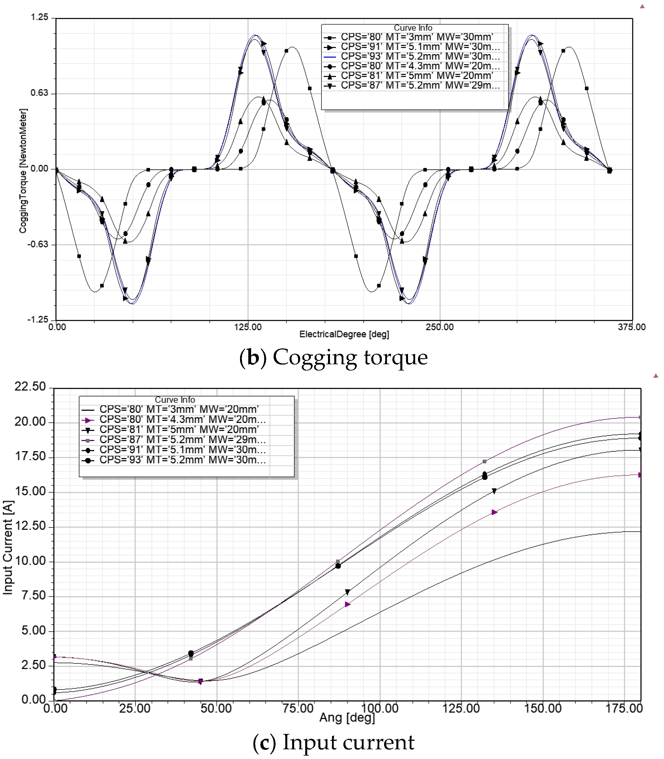
The optimetric analysis is applied to two optimization scenarios for the IPMSM. In the first model, three parameters—magnet length, magnet width, and the number of conductors per slot—are varied within the boundaries defined in Table 1. The motor’s operating characteristics are calculated for each combination of these parameters, resulting in 3542 unique configurations, each with its corresponding performance metrics. From these 3542 combinations, six motors are selected, exhibiting significant variations in efficiency, maximum output power, cogging torque, and magnet material consumption. The motor selections presented in Table 2 are based on efficiency, which serves as the key criterion. To highlight the importance of properly combining the varied parameters, we present the models with the highest and lowest efficiency. These models were selected based on the designer’s experience, as the parametric analysis generates many motor configurations by exploring all possible parameter combinations. The designer determines which output performance metrics to extract from the calculations in the optimetric analysis module within Ansys 17.1. For this study, the selected outputs include efficiency, cogging torque, maximum output power, magnet mass, and line current. Among these five output characteristics, the highest efficiency and the lowest efficiency is the criteria for selecting the motors in Table 2. These parameters enable the designer to assess the relative importance of each characteristic based on the specific application requirements. Consequently, the designer can either identify the optimal motor configurations or make informed trade-offs between competing performance metrics, as enhancements in one parameter (e.g., efficiency) may adversely impact others (e.g., cogging torque or magnet weight). The data presented in Table 2 for all motor models correspond to the rated operating conditions: a rated speed of 1500 rpm, rated load, supply voltage of 380 V, frequency of 50 Hz, and an operating temperature of 75 °C. The operating temperature is considered when calculating stator winding resistance and copper losses. All motors utilize rare-earth SmCo28 magnets, characterized by a residual flux density of Br = 1.038 T and a coercive field of Hc = −820,000 A/mH. The selected models, referred to as M1-1 to M1-6, along with their key operating parameters, are presented in Table 2.
The results presented in Table 2 indicate that the operating characteristics of the motors vary significantly depending on the design parameters. For example, efficiency ranges from 91.13% to 94.6%, influenced by magnet dimensions and the number of conductors per slot. This highlights the importance of careful parameter selection during the design process, as even small changes can lead to substantial differences in performance. For comparison, the Toshiba internal permanent magnet synchronous motor (IPMSM), rated at 2.2 kW, six poles, 1800 rpm, with frame size 100L and a rated current of 3.65 A, achieves an efficiency of 92.5% [26]. This motor is comparable to model M1-4. Since all motors presented in Table 2 are derived from a common computational model—where only the magnet dimensions and the number of conductors per slot are varied—the results generated using Ansys software 17.1 can be considered sufficiently accurate for assessing and comparing motor performance across different design configurations.
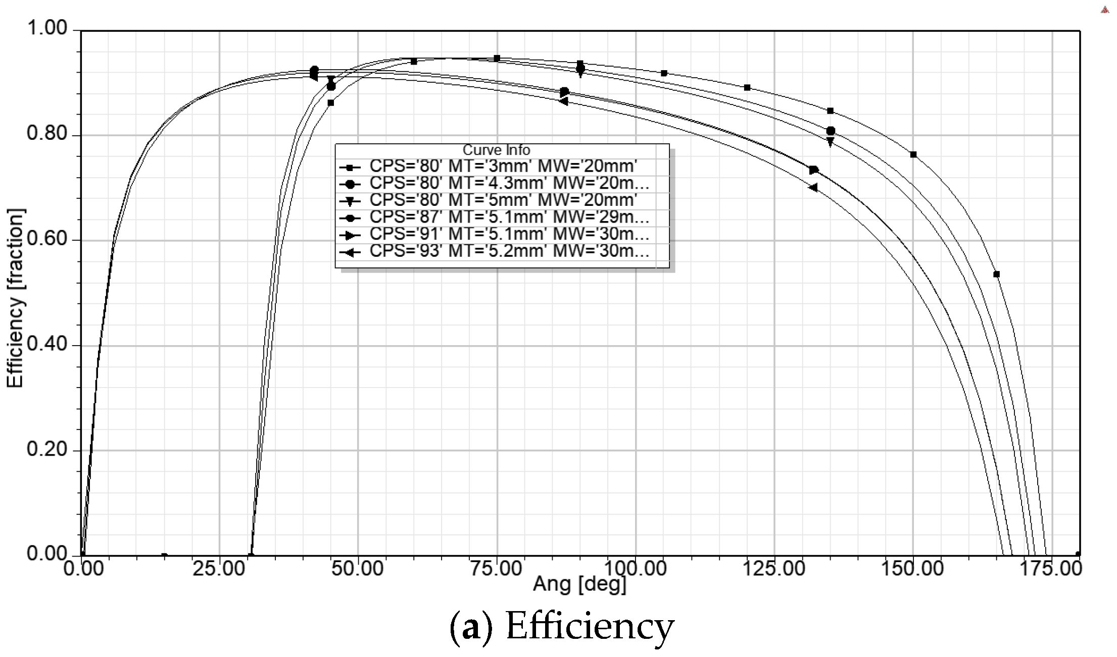
The data presented in Table 2 are supported by Figure 2, which comparatively illustrate the characteristics of efficiency, cogging torque, and line current for motors M1-1 to M1-6, respectively.
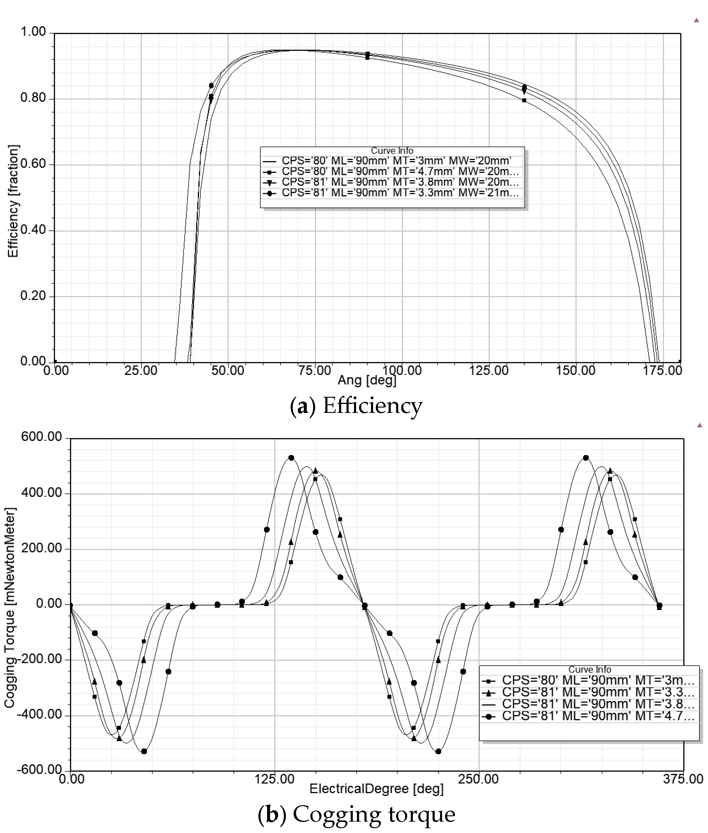
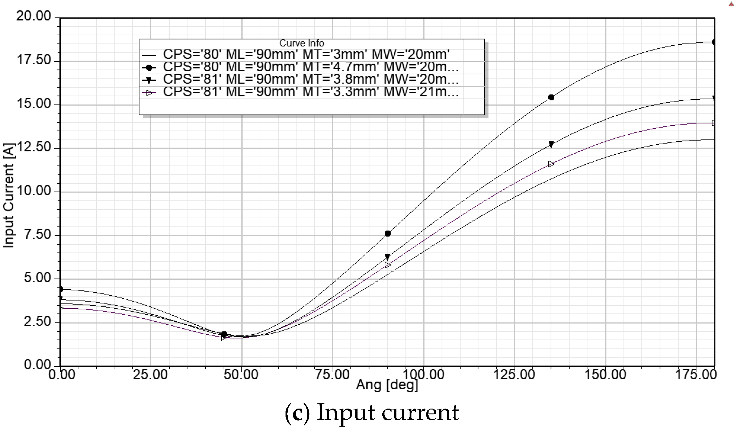
Motor length was added as the fourth varied parameter, in addition to the three previously mentioned, resulting in 16,698 unique motor configurations. Four motors were selected based on their highest efficiency. The selected models, referred to as M2-1 to M2-4, along with their operating parameters, are presented in Table 3. To illustrate the influence of the four varied design parameters on motor operating characteristics, model M2-5—selected for having the lowest efficiency of 92.5%—is included in Table 3. However, this model is not further analyzed in the paper due to its relatively high cogging torque and large permanent magnet mass, which render it less favourable for practical implementation. The data presented in Table 3 for all models correspond to the rated operating conditions: a rated speed of 1500 rpm, rated load, a supply voltage of 380 V, a frequency of 50 Hz, and an operating temperature of 75 °C. The operating temperature of 75 °C is considered in calculating the stator winding resistance and copper losses. All motors use rare-earth magnets, SmCo28, with residual flux density Br = 1.038T and coercive field Hc = −820,000 A/m.
The data presented in Table 3 are supported by Figure 3, which comparatively illustrate the characteristics of efficiency, cogging torque, and line current for motors M2-1 to M2-4, respectively.
Based on the analysis of all the models presented in Table 2 and Table 3, and considering the operating parameters such as high efficiency, low cogging torque, minimal permanent magnet material consumption, and good maximum output power, the motor M1-2 from the first model in Table 2 is selected as the optimal solution.
From the second model presented in Table 3, two candidates—M2-2 and M2-4—are considered for the optimal solution. The M2-2 motor exhibits low permanent magnet consumption, relatively high efficiency, and low cogging torque. However, its drawback is a relatively low maximum output power. Similar analysis is valid for the M2-1 motor.
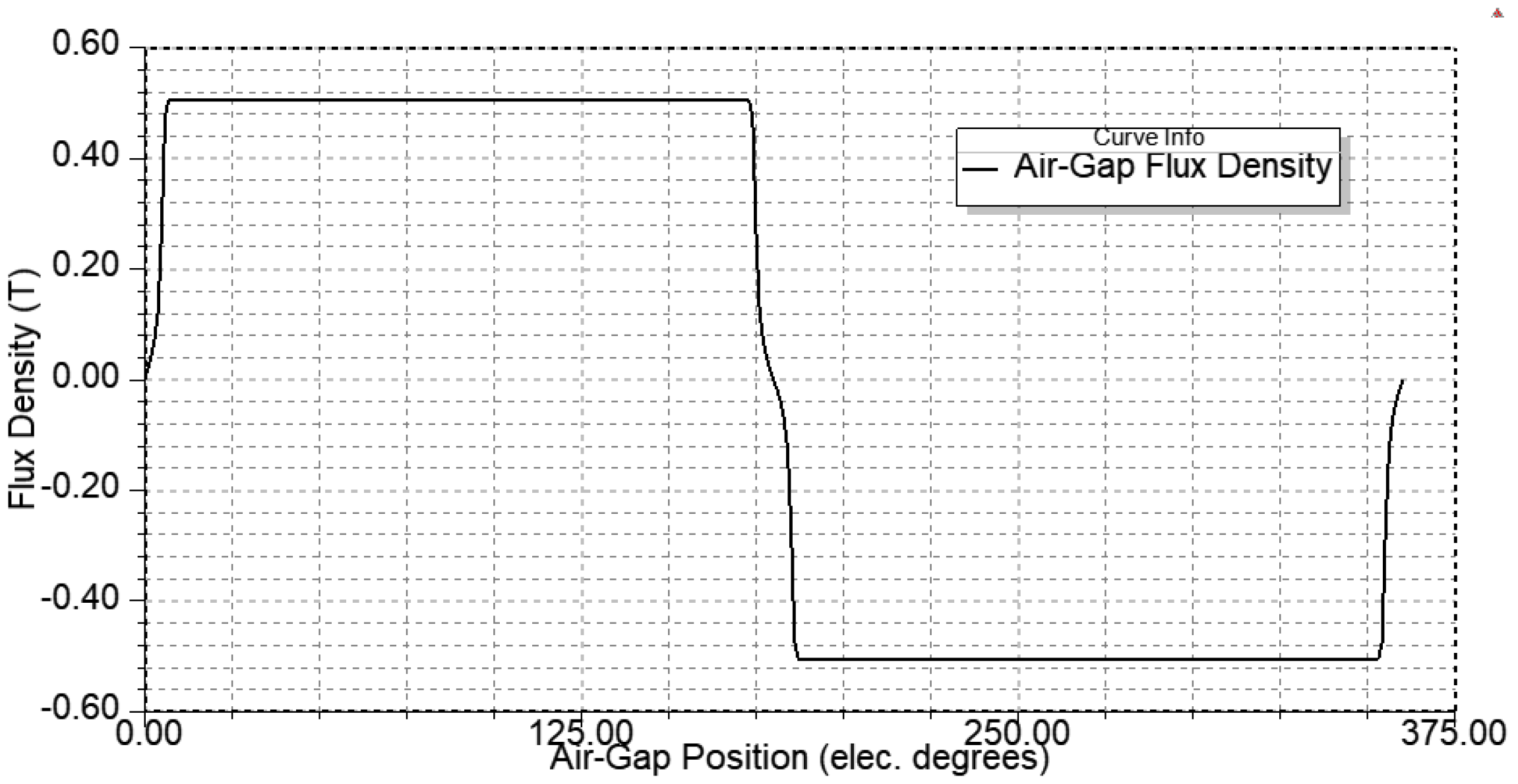
Therefore, considering the highest efficiency, good maximum output power, the lowest cogging torque, and relatively low permanent magnet consumption, the M2-4 motor is selected as the most optimal candidate. For the M2-4 motor, the flux density distribution in the air gap is presented in Figure 4.
The M2-4 design is analyzed using finite element analysis (FEA) to determine the magnetic flux density distribution in the motor cross-section. Over the years, FEA has proven to be a valuable tool in machine design, enabling the detection of areas within the ferromagnetic core that are prone to saturation. This helps identify weak points in the motor construction and contributes to the overall improvement of machine design.
Figure 5 presents the flux density distribution in the cross-section of the M2-4 motor.
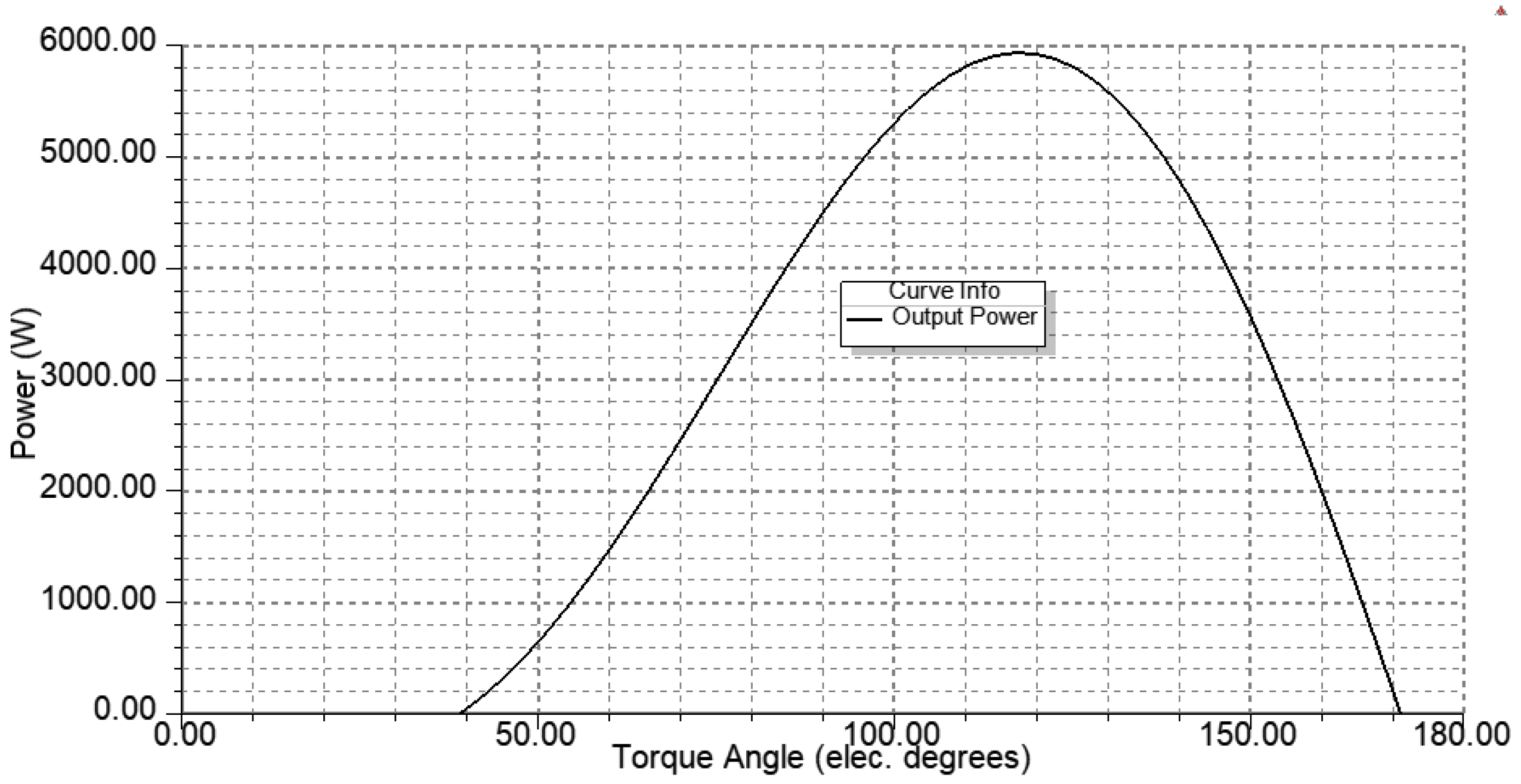
The developed output power is presented in Figure 6 to illustrate the maximum power that can be generated by this motor model.
The spoke-type permanent magnet synchronous motor is derived from an asynchronous motor by replacing the rotor while keeping the rest of the construction unchanged. The derived M2-4 synchronous motor model, with a shortened length, is compared to the original asynchronous squirrel cage motor, which has a length of 110 mm.
Additionally, the asynchronous motor model, referred to as the model AM, is compared with the manufacturer’s catalogue data, i.e., motor type E5AZ 100LA-4 of IE2 class. Notably, the same number of conductors per slot is used in both the synchronous and asynchronous motors. The only difference between them, aside from the rotor construction—where the squirrel cage winding is replaced with permanent magnets—is the machine length.
Table 4 presents a comparison of the operating parameters of M2-4, AM, and the manufacturer’s data.
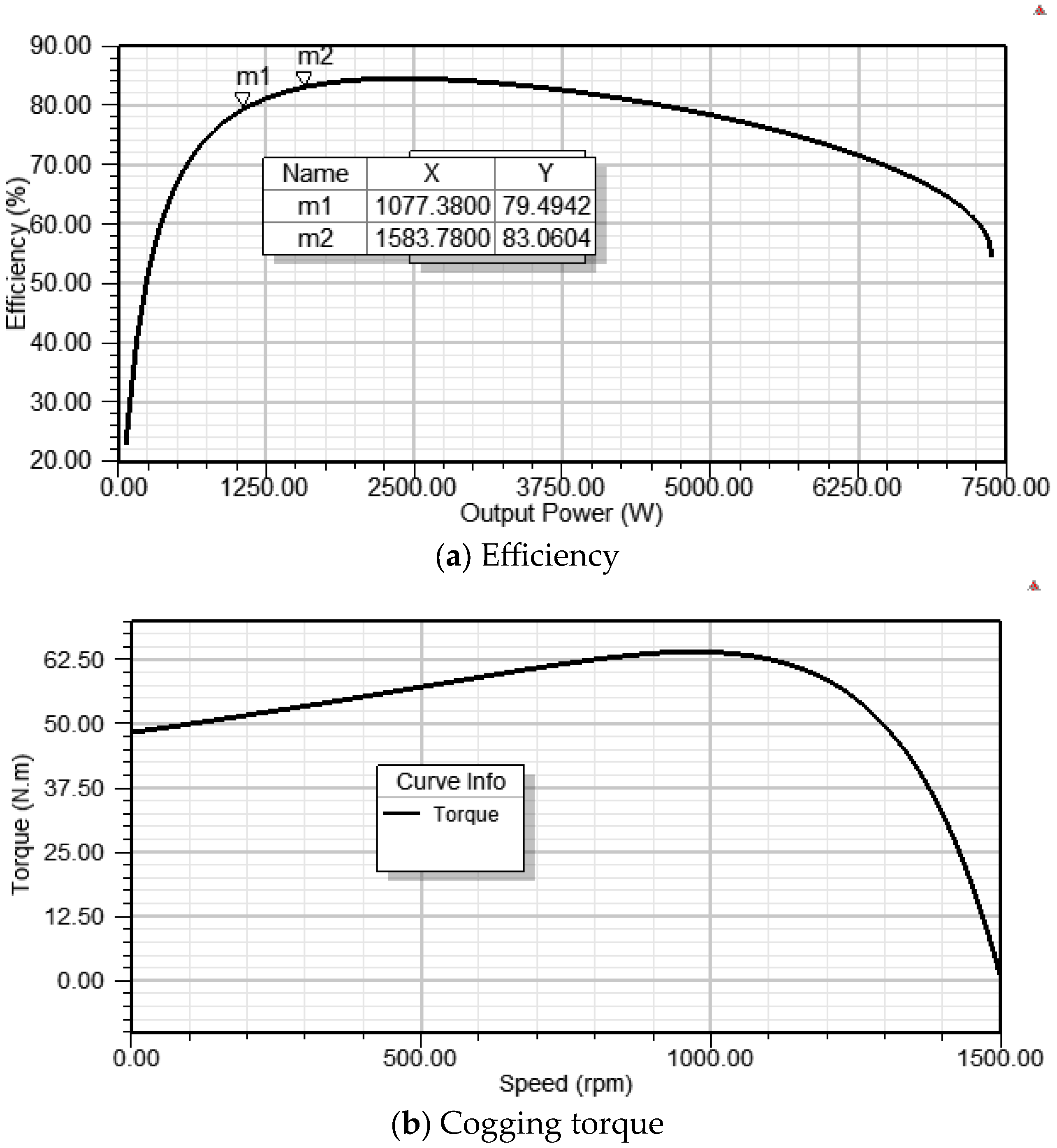
The operating characteristics of the model AM, including efficiency versus motor output power, torque versus speed, and power factor versus output power, are shown in Figure 7. This figure supports the data presented in Table 4, providing a visual representation of the motor’s performance. The model of the asynchronous motor and its comparison with the catalogue data provides verification of the created models, i.e., their similarity with the physical machine.
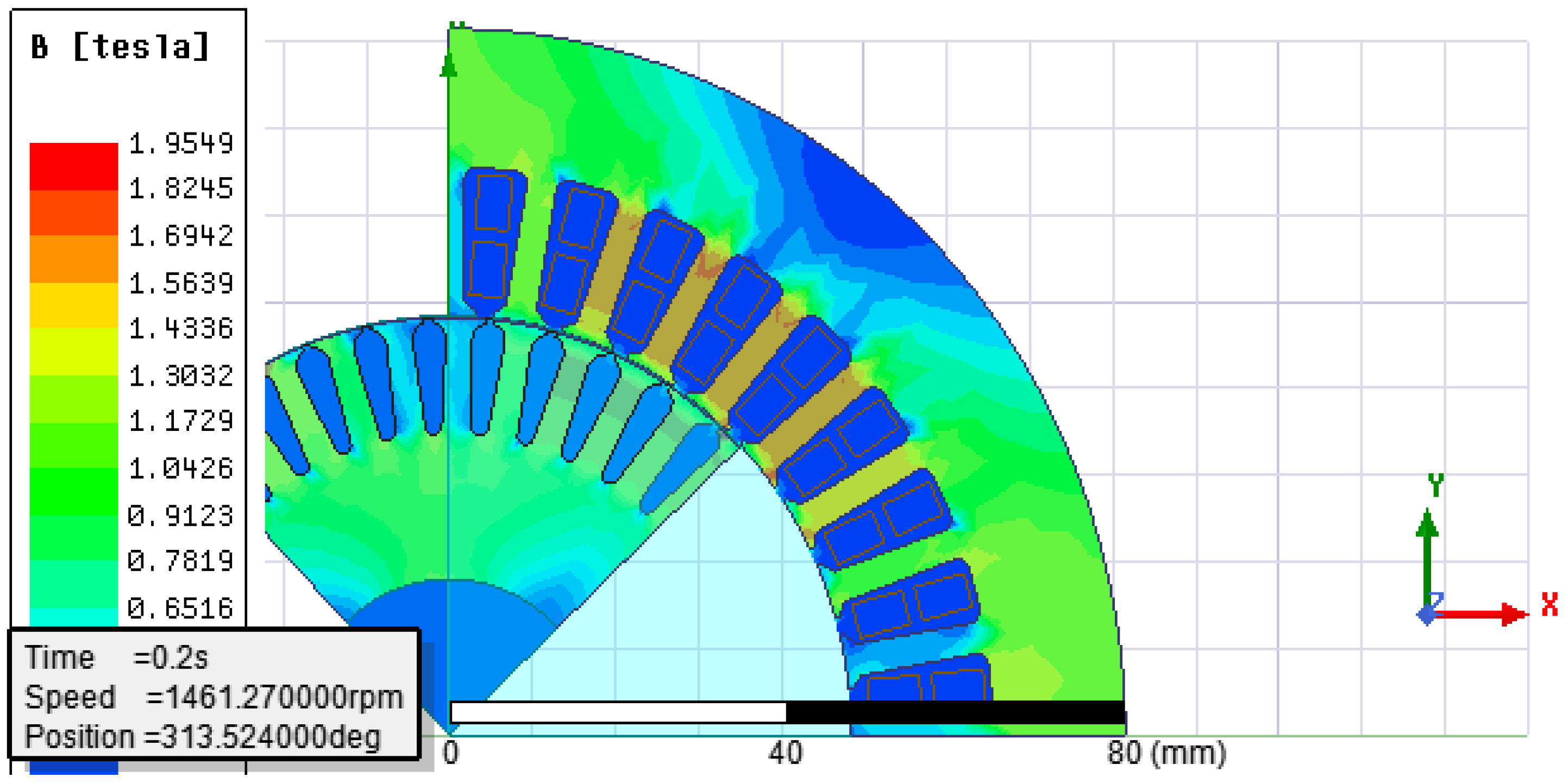
Furthermore, finite element analysis (FEA) is performed on the AM model, and the resulting magnetic flux density distribution in the motor’s cross-section is shown in Figure 8. The latter serves as the basis for comparing the designs of both the asynchronous and synchronous motors.

5. Discussion

Limited energy resources highlight the need for efficient electricity usage. Electric motors are among the largest consumers of electricity, making their continuous improvement—focusing on higher efficiency and reduced losses—essential for energy savings. According to the existing EU regulations, all motors that are in operation in the EU must achieve a certain efficiency class. IE3 efficiency class is mandatory for all three-phase motors between 0.74 kW and 1000 kW. From July 2023, IE4 class is mandatory for motors between 75 kW and 200 kW [27]. These strict requirements present new challenges for motor designers; for example, improving one operating parameter—such as efficiency—can often negatively impact others, such as overloading capability or cogging torque. Moreover, higher efficiency is often associated with increased production costs due to larger dimensions or the use of higher-quality materials. Three-phase asynchronous squirrel cage motors are the most widely used in electrical drives due to their simplicity, low production costs, and minimal maintenance requirements. However, achieving higher efficiency classes, as required by EU regulations, with this type of motor comes with increased production costs. This is because improving efficiency often necessitates larger motor dimensions and an increased number of conductors in the stator slots, requiring more high-quality materials with low specific losses. Additionally, it may involve replacing the aluminum squirrel cage winding in the rotor with a copper one. On the other hand, synchronous permanent magnet motors offer high efficiency, making it easier to achieve IE3 and IE4 efficiency classes due to their operating principle. Unlike asynchronous motors, they have no rotor winding, as it is replaced by a permanent magnet. This eliminates induced voltage and, consequently, copper losses in the rotor winding, further enhancing efficiency. Advancements in power electronics have solved the issue of starting synchronous motors, which are not inherently self-starting and require an inverter for operation. Synchronous motors with embedded magnets in the rotor are available in various configurations, distinguished by the position and shape of the magnets within the rotor core. The spoke-type synchronous permanent magnet motor is known for its excellent flux-concentrating capabilities. In this design, the magnets are inserted into the rotor in a radial direction. This type of interior permanent magnet synchronous motor (IPMSM) can be used with ferrite magnets, which are rarely used in permanent magnet motor applications due to their low remanent magnetism, making it challenging to achieve high torque densities. The spoke-type topology generates higher flux densities in the air gap and achieves greater torque density compared to other topologies using ferrite permanent magnets [18]. Simple design modifications in spoke-type synchronous permanent magnet motors can reduce the weight of the permanent magnets, making the design more cost-effective, even when using rare-earth magnets. The first motor model incorporates three varying parameters related to the dimensions of the permanent magnets (length and width) and the stator winding parameters, specifically the number of conductors per stator slot. According to the results in Table 2, different combinations of these parameters enable a wide range of motor designs, each with significantly different operating characteristics. The M1-1 motor has the lowest permanent magnet weight but also lower maximum output power. However, it exhibits the smallest cogging torque among all the motors presented in Table 2. Cogging torque can be a significant drawback in permanent magnet motors with embedded magnets, particularly in applications requiring smooth operation, such as electromobility, where it can cause noise and vibrations during motor operation. According to [28], torque ripple in the machine originates from three sources:
-
The interaction between the permanent magnet flux and the varying air gap permeance caused by the stator slot geometry;
-
Distortions in the sinusoidal or trapezoidal distribution of magnet flux density in the air gap;
-
Differences in air gap permeance along the d- and q-axes.
The cogging torque is independent of the stator load and its frequency is
f c = Z 1 p f
where Z1 is the number of stator slots, p is the pair of poles, and f is the supply frequency. Neglecting the energy stored in the ferromagnetic core the cogging torque can be expressed as [28]:
T c = d W d θ = D 2 o u t 2 d W d x
where θ = 2x/D2out, where D2out is the rotor outer diameter, θ is the mechanical angle, W is the energy stored in the air gap, and x is the air gap length.
There are several methods to reduce cogging torque, including skewing and shifting permanent magnets, modifying stator slot shapes (e.g., closed and bifurcated slots, dummy slots), selecting an optimal number of stator slots and pole pairs, and skewing the stator slots. However, these design modifications increase motor construction complexity, as they require redesigning the stator core, new laminations, additional labour for mounting the stator winding into closed slots, and extra materials for closing the slots with magnet wedges. Additionally, skewing stator slots or rotor magnets increases both costs and design complexity. The design analysis in this paper begins with a 2.2 kW asynchronous squirrel cage motor, with the goal of redesigning it into a synchronous motor while making minimal modifications, particularly by retaining the same stator lamination. The redesign primarily focuses on the rotor, minimizing modifications as much as possible. As a result, the M1-1 to M1-3 motors achieve low cogging torque, high efficiency, and reduced magnet weight with only minor changes to the rotor design. In contrast, the M1-4 to M1-6 motors have lower efficiency but offer excellent maximum output power, a higher permanent magnet weight, and relatively high cogging torque. According to [19], cogging torque should not exceed 10% of the average torque. All motors presented in Table 2 meet this criterion. However, these motors differ significantly in terms of efficiency, overloading capability, and permanent magnet weight. The M1-2 motor is selected as the best candidate among those presented in Table 2, as it represents a reasonable compromise between high efficiency, good overloading capability, and relatively low magnet weight and cogging torque. The drawback of the M1-1 motor is its poor maximum output power, while the M1-3 motor has a larger magnet weight than the M1-2 motor. According to [29], a synchronous motor with permanent magnets can outperform an asynchronous motor, even with a shorter length. The second motor model is computed by adding the motor length as the fourth variable, resulting in the motors presented in Table 3. These motors are the most successful candidates from all obtained combinations in terms of efficiency, along with the other previously mentioned operating characteristics. Although the M2-1 motor has the smallest permanent magnet weight and cogging torque, it has low maximum output power and, therefore, cannot be considered the optimal design. Motors M2-2 to M2-4 offer high efficiency, good maximum output power, low permanent magnet consumption, and relatively low cogging torque. Evaluating overall motor performance, it can be concluded that the M2-4 motor offers the greatest overloading capability, along with the highest efficiency and power factor. The cogging torque is 0.53 Nm, which is 3.8% of the rated torque. Although the M2-4 motor has the largest permanent magnet weight among all the motors presented in Table 3, its other operating characteristics outperform the remaining three motors. Therefore, the M2-4 motor is selected as the most optimal solution among those presented in Table 3. However, it is interesting to compare the selected motors as the most optimal designs from both models, i.e., from Table 2 and Table 3, the M1-2 motor and the M2-4 motor. This comparison is presented in Table 5.
The M2-4 motor is superior in terms of efficiency, maximum output power, and cogging torque when compared with the M1-2 motor. Both motors have nearly the same permanent magnet consumption and almost identical power factors. Additionally, the M2-4 motor has a reduced length, meaning it has smaller dimensions and less core material. Therefore, the M2-4 motor is selected as the most optimal design, pending further evaluation through FEA and sensitivity analysis. Motor M2-4 was selected based on efficiency as the primary performance criterion. To enable a comparative assessment, the motor was also optimized using genetic algorithms (GAs), with efficiency defined as the objective function. The results from the GA-based optimization are compared against those obtained from the optimetric analysis. To ensure the results from the GA optimization are comparable with those from the optimetric analysis, the same parameter variation ranges were used for the four variables—CPS, ML, MT, and MW—as defined in Table 1. The model obtained from the GA optimization is referred to as M-GA. Similarly, using the same parameter variation ranges as in the GA optimization, sequential nonlinear programming (SNP) was applied with efficiency as the objective function, yielding a second optimized model, referred to as M-SNP. A comparison of the three motors—M2-4, M-GA, and M-SNP—is presented in Table 6. The results indicate a high degree of similarity among the optimization methods: the M2-4 motor achieves an efficiency of 94.86%, the M-SNP motor 94.87%, and the M-GA motor 94.78%.
The optimization methods applied in this study—genetic algorithms (GAs) and sequential nonlinear programming (SNP)—utilize a single objective function: efficiency. As a result, the optimal model obtained through SNP achieves the highest efficiency among all three models. However, this comes at the cost of a slight increase in cogging torque and permanent magnet mass compared to the M2-4 and M-GA models. The model obtained through GA optimization utilizes optimal values for CPS, MT, MW, and ML, which need to be approximated to practical, rounded values for prototype manufacturing. This rounding may lead to deviations from the original optimization results. Future research could focus on the application of multi-objective optimization techniques to identify optimal designs that balance multiple objectives—such as maximizing efficiency while minimizing magnet mass and cogging torque. The results presented in Table 6 validate the selected optimal design of the spoke-type permanent magnet synchronous motor, obtained through optimetric analysis (parametric modelling), as sufficiently accurate. Figure 9 shows the maximum output power for the M-GA and M-SNP models, with noticeable differences in their respective values. These variations are clearly depicted in the figure. The results presented in Figure 9 are consistent with the data provided in Table 6.
However, a limitation of the optimetric approach is its heavy reliance on the designer’s judgement in selecting the optimal design. This is due to the large number of possible parameter combinations—e.g., with four varied parameters, there are 16,698 possible configurations—requiring careful evaluation of a vast design space. Selecting the optimal design can be a time-consuming task, heavily influenced by the designer’s experience and the thoroughness with which the results are analyzed.
The impact of each varied parameter on efficiency and cogging torque is analyzed by varying only one parameter while keeping the remaining three equal to the values given in Table 3. For instance, Figure 10a shows the M2-4 motor with MT, MW, and ML set to the values in Table 3, while the CPS is the only varied parameter. Therefore, the impact of the CPS on motor efficiency is presented. Similarly, the same approach is applied to Figure 10b–d, where the impact of MT, MW, and ML on motor efficiency is presented. In Figure 9a, efficiency decreases as the number of conductors per slot increases. The curve shows sharp drops when CPS changes from 82 to 83 conductors. This is due to a change in the wire diameter, which decreases in the motor with 82 conductors, thereby increasing the stator resistance. The impact of this increased resistance on copper losses is higher than the impact of the stator current. The software automatically adjusts the wire diameter to maintain a good fill factor within the limits of the slot fill factor.
The increase in MT enhances efficiency, a finding also reported in [30]. On the other hand, the increase in magnet width and motor length has an adverse effect on efficiency. The designed spoke-type permanent magnet synchronous motor achieves high efficiency for a 2.2 kW motor, and further reducing the motor length improves efficiency by decreasing iron core and copper losses. Similar efficiency values for a 2.2 kW spoke-type synchronous motor can be found in [31]. From the diagrams presented in Figure 10, it is evident that magnet width has the greatest impact on motor efficiency. The number of conductors per slot is the second most influential parameter on motor efficiency. Motor length and magnet thickness have a minor impact on efficiency. However, it should be noted that the right combination of all four parameters is critical for achieving an optimal design with respect to several objectives, i.e., the operating characteristics of the motor. The optimization with multiple objective functions and the impact of correlated parameters on these objectives is also presented in [8]. The impact of each of the four varied parameters on cogging torque is presented in Figure 11. The same approach is followed as in the case of efficiency, where one parameter is varied while the other three are kept constant and equal to the values presented in Table 3. According to the results presented in Figure 11, the number of conductors per slot has no impact on cogging torque. However, increases in magnet thickness, magnet width, and machine length significantly affect cogging torque. This conclusion is supported by the findings in [32]. Finally, the comparison between the selected M2-4 motor and the corresponding three-phase squirrel cage motor is presented in Table 4. Figure 6 supports data presented in Table 4. Apart from the rotor design (i.e., permanent magnets are replaced with squirrel cage winding), the motor length is increased to 110 mm while the remaining details of motor construction remain the same as in the synchronous motor.
The reason for increasing the motor length is to achieve a more efficient asynchronous motor, comparable to class IE2 and the data provided by the manufacturer [25]. For instance, an asynchronous motor length of 100 mm results in an efficiency of 79%, which is comparable to the IE1 class. The comparison of the asynchronous motor model data with the manufacturer’s data shows good similarity, verifying the design as sufficiently accurate and providing a solid starting point for designing the synchronous motor. Moreover, it is evident that the synchronous motor, with smaller dimensions, outperforms the asynchronous motor in terms of several operating characteristics: efficiency, power factor, and overall dimensions. However, it should be noted that the optimized model M2-4 is a simulation-based design. In practice, the prototype is expected to exhibit a slightly lower efficiency and power factor due to manufacturing constraints and real-world operating conditions. The comparison of the data in Table 4 supports well-known advantages of synchronous motors over asynchronous motors, such as better efficiency, smaller dimensions, excellent power factor, and lower line current. This allows for smaller cable cross-sections and associated equipment, as stated in [29], resulting finally in smaller operating costs for the same application, although the initial price of the synchronous motor is higher than the asynchronous [29]. Considerable savings can be made in electricity costs due to the increased efficiency of the synchronous motor. However, each of these two types of motors is suitable for specific applications. The synchronous motor is commonly used where constant speed is required, as it operates very efficiently under steady loads and is ideal for systems that need high precision and speed consistency. On the other hand, asynchronous motors are inexpensive, easy to manufacture and maintain, and are robust with a long operating life. These characteristics make them ideal for demanding environments, which is why they are widespread in industrial automation systems. Using ferrite magnets and replacing rare-earth magnets can make this type of synchronous motor a more cost-effective product. Further research could focus on cost-effective solutions for the spoke-type permanent magnet synchronous motor by utilizing ferrite magnets and improving the rotor design. However, the rotor’s mechanical strength should also be examined, and any necessary improvements should be proposed as part of future research.

6. Conclusions

The paper highlights the need for careful evaluation of various parameters when designing the spoke-type synchronous permanent magnet motor, as there are numerous motor models derived from various combinations of several design parameters that can be varied within certain boundaries. The obtained results, which represent various operating characteristics, can be examined in terms of several factors, allowing the designer the freedom to select the most optimal solution. However, this often means the chosen solution may not be the best in terms of all operating characteristics. The software module optimetrics are applied in motor design, allowing for the optimal design of the spoke-type synchronous motor with the highest efficiency, relatively low cogging torque, minimal permanent magnet consumption, and notable maximum output power to be selected. The optimization is achieved through simple modifications in rotor design and stator winding, resulting in lower production costs and unchanged production processes. The designer decides, based on the obtained results, which model is most suitable for a certain application, or which operating characteristics are of paramount importance, and which are a compromise, as the optimal design is selected from the family of models. The optimal model is obtained through a two-step optimetric analysis: one with three varied parameters and one with four varied parameters. As the model becomes more complex, the computational time increases, which is one drawback of the presented analysis. The selected optimal design achieves high efficiency, good overloading capability, small permanent magnet weight, and low cogging torque. The optimal design is based on selection from numerous motor models, with operating characteristics that vary in wide range and are directly corelated with the selected varying parameters, therefore highlighting the need for careful selection of varied parameters and careful evaluation of obtained results. The impact of each varied parameter—magnet width and thickness, number of conductors per stator, and motor length—on efficiency and cogging torque is presented and analyzed, providing valuable insights into the effect of each parameter on the design objectives. Finally, the synchronous motor is compared with the asynchronous squirrel cage motor, as the synchronous motor is essentially derived from the asynchronous motor by replacing the rotor and reducing the motor length. This approach is chosen because it represents a cost-effective solution, reducing production costs. The comparison highlights several advantages of the synchronous motor over the asynchronous motor, such as improved efficiency, power factor, and smaller dimensions. The aim of this paper is to demonstrate that significant improvements in key operating characteristics of spoke-type synchronous motors with rare-earth magnets—such as efficiency, cogging torque, and permanent magnet mass—can be achieved through simple modifications to the rotor design, machine length, and the number of winding turns. The paper highlights the importance of carefully evaluating the values of each design parameter—magnet length and width, machine length, and the number of conductors per slot—since their combinations lead to numerous designs with a wide range of operating characteristics, which can vary significantly. The simplicity of the presented methodology, combined with its cost-effectiveness, enables a wide range of applications in the industry for the production of electric motors. The spoke-type synchronous permanent magnet motor is selected for the analysis, as this configuration is under research for the use of ferrite magnets instead of expensive rare-earth magnets. Further research is needed to justify the application of ferrite magnets and assess their impact on motor operation.

Author Contributions

Conceptualization, V.S., D.M., S.A. and P.J.; methodology, V.S., S.A., D.B. and A.A.; software, D.B. and A.A.; validation, D.M., P.J. and V.S.; formal analysis, M.F.S.; investigation, M.F.S.; resources, V.S. and S.A.; data curation, D.B. and A.A.; writing—original draft preparation, V.S.; writing—review and editing, D.M. and P.J.; visualization, D.B.; supervision, D.M.; project administration, D.M.; funding acquisition, V.S. and D.M. All authors have read and agreed to the published version of the manuscript.

Funding

This research received no external funding.

Data Availability Statement

The original contributions presented in this study are included in the article. Further inquiries can be directed to the corresponding author.

Conflicts of Interest

The authors declare no conflicts of interest.

Abbreviations

The following abbreviations are used in this manuscript:
PMSMPermanent magnet synchronous motor
IPMSMInterior permanent magnet synchronous motor
SPMSMSurface permanent magnet synchronous motor
EMFElectro-motive force
EVElectrical vehicles
MTMagnet thickness
MLMagnet length
CPSConductors per slot
MLMotor length
AMAsynchronous motor
FEAFinite element analysis
M-GAGenetic algorithms model
M-SNPSequential nonlinear programming model
GAGenetic algorithm
SNPSequential nonlinear programming

References

  1. Anand, M.; Sundaram, M.; Sivakumar, P.; Angamuthu, A. Development of high-temperature permanent magnet synchronous motor for autonomous robotic navigation: A design and finite element analysis approach. Bull. Pol. Acad. Sci. 2024, 72, e150108. [Google Scholar] [CrossRef]
  2. Sekerák, P.; Hrabovcová, V.; Pyrhönen, J.; Kalamen, L.; Rafajdus, P.; Onufer, M. Ferrites and different winding types in permanent magnet synchronous motor. J. Electr. Eng. 2012, 63, 162–170. [Google Scholar] [CrossRef]
  3. Jung, W.-S.; Lee, H.-K.; Lee, Y.-K.; Kim, S.-M.; Lee, J.-I.; Choi, J.-Y. Analysis and Comparison of Permanent Magnet Synchronous Motors According to Rotor Type under the Same Design Specifications. Energies 2023, 16, 1306. [Google Scholar] [CrossRef]
  4. Balasubramanian, L.; Bhuiyan, N.A.; Javied, A.; Fahmy, A.A.; Belblidia, F.; Sienz, J. Design and Optimization of Interior Permanent Magnet (IPM) Motor for Electric Vehicle Applications. CES Trans. Electr. Mach. Syst. 2023, 7, 202–209. [Google Scholar] [CrossRef]
  5. Vărănticeanu, B.D.; Miniunescu, P.; Fodorean, D. Mechanical design and analysis of permanent magnet rotor used in high-speed synchronous motor. Electrotech. Elektron. Autom. 2014, 62, 9–16. [Google Scholar]
  6. Yang, F.; Li, N.; Du, G.; Huang, M.; Kang, Z. Electromagnetic Optimization of a High-Speed Interior Permanent Magnet Motor Considering Rotor Stress. Applies Sci. 2024, 14, 6033. [Google Scholar] [CrossRef]
  7. Beser, E.K. Electrical equivalent circuit for modelling permanent magnet synchronous motors. J. Electr. Eng. 2021, 72, 176–183. [Google Scholar] [CrossRef]
  8. Xu, Y.; Chen, Y.; Fu, Z.; Xu, M.; Liu, H.; Cheng, L. Design and Analysis of an Interior Permanent Magnet Synchronous Motor for a Traction Drive Using Multiobjective Optimization. Int. Trans. Electr. Energy Syst. 2024, 3631384. [Google Scholar] [CrossRef]
  9. Yetis, H.; Goktas, T. Comparative Design of Permanent Magnet Synchronous Motors for Low-Power Industrial Applications. Balk. J. Electr. Comput. Eng. 2020, 8, 218–224. [Google Scholar] [CrossRef]
  10. Xu, X.; Wu, S.; Chen, Y.; Zhang, J.; Li, G.; Yan, C.; Tan, Z.; Peng, D. Heat dissipation design and performance optimization of high speed train PMSM based on coupled electromagnetic-thermal field. Case Stud. Therm. Eng. 2024, 61, 104904. [Google Scholar] [CrossRef]
  11. Gecic, M.; Marcetic, D.; Vasic, V.; Krcmar, I.; Matic, P. Towards an Improved Energy Efficiency of the Interior Permanent Magnet Synchronous Motor Drives. Serbian J. Electr. Eng. 2014, 11, 257–269. [Google Scholar] [CrossRef]
  12. Mi, C.C.; Slemon, G.R.; Bonert, R. Minimization of Iron Losses of Permanent Magnet Synchronous Machines. IEEE Trans. Energy Convers. 2005, 20, 121–127. [Google Scholar] [CrossRef]
  13. Gundogdu, T.; Komurgoz, G. The Impact of the Selection of Permanent Magnets on the Design of Permanent Magnet Machines—A Case Study: Permanent Magnet Synchronous Machine Design with High Efficiency. Prezgląd Electrotech. 2013, 89, 103–108. [Google Scholar]
  14. Kong, Y.; Xu, D.; Lin, M. Efficiency modeling and comparison of surface and interior permanent magnet machines for electric vehicle. Energy Rep. 2023, 9, 419–426. [Google Scholar] [CrossRef]
  15. Todorov, G. Analysis of the torque ripple of permanent magnet synchronous motors with inset and embedded magnets. E+E 2015, 11–12, 49–53. [Google Scholar]
  16. Ferková, Ž. Influence of the arrangement and sizes of magnets on the cogging torque of PMSM. Tech. Trans. 2015, 1-E, 161–171. [Google Scholar] [CrossRef]
  17. Song, S.-W.; Kim, W.-H.; Lee, J.; Jung, D.-H. Design to Reduce Cogging Torque and Irreversible Demagnetization in Traction Hybrid Motor Using Dy-free Magnet. Machines 2023, 11, 345. [Google Scholar] [CrossRef]
  18. Silva, M.D.; Eriksson, S. On the relation between performance and permanent demagnetisation in spoke type machines with ferrite magnets. IET Electr. Power Appl. 2024, 18, 912–923. [Google Scholar] [CrossRef]
  19. Bahrim, F.S.; Sulaiman, E.; Kumar, R.; Jusoh, L.I. Cogging Torque Reduction Techniques for Spoke-type IPMSM. IOP Conf. Ser. Mater. Sci. Eng. 2017, 226, 012128. [Google Scholar] [CrossRef]
  20. Si, M.; Yang, X.Y.; Zhao, S.W.; Gong, S. Design and analysis of a novel spoke-type permanent magnet synchronous motor. IET Electr. Power Appl. 2016, 10, 571–580. [Google Scholar] [CrossRef]
  21. Yoon, K.-Y.; Baek, S.-W. Performance Improvement of Concentrated-Flux Type IPM PMSM Motor with Flared-Shape Magnet Arrangement. Appl. Sci. 2020, 10, 6061. [Google Scholar] [CrossRef]
  22. Seok, C.-H.; Choi, H.-S.; Seo, J. Design and analysis of a novel spoke-type motor to reduce the use of rare-earth magnet materials. IET Electr. Power Appl. 2021, 15, 1479–1487. [Google Scholar] [CrossRef]
  23. Kim, D.-H.; Pyo, H.-J.; Kim, W.-H.; Lee, J.; Lee, K.-D. Design of Spoke-Type Permanent Magnet Synchronous Generator for Low Capacity Wind Turbine Considering Magnetization and Cogging Torques. Machines 2023, 11, 301. [Google Scholar] [CrossRef]
  24. Končar: Electric Motors. Available online: http://koncar.hr/sites/default/files/dokumenti/mediji/2024-09/KONČAR-MES_Katalog-Elektromotori.pdf (accessed on 12 March 2025).
  25. Sarac, V.; Bogatinov, D.; Aneva, S. Impact of Faulty Conditions of Power Supply on Operating Characteristics of Three-Phase Asynchronous Squirrel Cage Motor. In Proceedings of the 33rd International Conference on Organization and Technology of Maintenance (OTO 2024), Slavonski Brod, Croatia, 12 December 2024. [Google Scholar]
  26. Toshiba: IPM Motor Series. Available online: http://sunnice.com/catalogue/pm-motor-catalog.pdf (accessed on 2 April 2025).
  27. EUR-Lex. Available online: https://eur-lex.europa.eu/eli/reg/2019/1781/oj (accessed on 12 March 2025).
  28. Gieras, J.F.; Wing, M. Permanent Magnet Motor Technology, 2nd ed.; Marcer Dekker Inc.: New York, NY, USA, 2002; pp. 247–261. [Google Scholar]
  29. Franklin Water EU Media. Available online: https://franklinwater.eu/media/586760/Comparative-calculation-asnchronous_synchronous-pumping_irrigation_EN.pdf (accessed on 12 March 2025).
  30. Yasa, Y. Design of High-Power Density Spoke-Type Interior Permanent Magnet Synchronous Motor for E-Bikes. J. Eng. Sci. Ad Resour. 2023, 5, 264–271. [Google Scholar]
  31. Breban, S.; Dranca, M.; Chirca, M.; Pacuraru, A.-M.; Teodosescu, P.-D.; Oprea, C.-A. Experimental Tests on a Spoke-Type Permanent Magnets Synchronous Machine for Light Electric Vehicle Application. Appl. Sci. 2022, 12, 3019. [Google Scholar] [CrossRef]
  32. Yulianto, K.; Yusivar, F.; Sudiarto, B. The Influence of Magnet Number and Dimension on Torque Characteristics in the Interior Permanent Magnet Synchronous Motor (PMSM). IOP Conf. Ser. Mater. Sci. Eng. 2021, 1158, 012006. [Google Scholar] [CrossRef]
Figure 1. Motor’s cross-section (a) asynchronous motor (b) spoke-type synchronous motor.
Machines 13 00375 g001
Figure 2. Comparative characteristics of models M1-1 to M1-6.
Machines 13 00375 g002aMachines 13 00375 g002b
Figure 3. Comparative characteristics of models M2-1 to M2-4.
Machines 13 00375 g003aMachines 13 00375 g003b
Figure 4. Air gap flux density distribution at M2-4.
Machines 13 00375 g004
Figure 5. Flux density distribution at M2-4.
Machines 13 00375 g005
Figure 6. Output power of M2-2 model.
Machines 13 00375 g006
Figure 7. Steady-state characteristics of AM.
Machines 13 00375 g007aMachines 13 00375 g007b
Figure 8. Flux density of AM.
Machines 13 00375 g008
Figure 9. Output power of M-GA and M-SNP.
Machines 13 00375 g009
Figure 10. Impact of varied parameters on efficiency for M2-4 motor.
Machines 13 00375 g010aMachines 13 00375 g010b
Figure 11. Impact of varied parameters on cogging torque for the M2-4 motor.
Machines 13 00375 g011aMachines 13 00375 g011b
Table 1. Ranges of variation in motor parameters for models M1 and M2.
ParameterM1M2Step
CPS (/)80 ÷ 10080 ÷ 851
MT (mm)3 ÷ 5.23 ÷ 5.20.1
MW (mm)20 ÷ 3020 ÷ 301
ML (mm)/90 ÷ 1001
Table 2. Models M1-1 to M1-6 and their operating parameters.
ParameterM1-1M1-2M1-3M1-4M1-5M1-6
CPS (/)808081879193
MT (mm)34.355.25.15.2
MW (mm)202020293030
Motor length (mm)100100100100100100
Rated voltage (V)380380380380380380
Output power (W)220022002200220022002200
Input power (W)2325.82322.482322.9723782389.92412.64
Stator winding phase resistance at 75 °C (Ω)1.911.911.932.322.432.79
Line/phase current (A)3.673.523.493.793.93.99
Copper losses (W)76.857170.65100.23111.2133.78
Core losses (W)26.8130.231.456.1657.958.14
Friction and windage losses (W)222222222222
Efficiency (%)94.694.794.6692.59291.13
Maximum output power (W)391352885879686865636346
Cogging torque (Nm)0.5190.5740.5991.071.111.11
Permanent magnet weight (kg)0.1990.2860.3320.50.510.52
Power factor (/)0.950.990.990.930.910.89
Torque angle (degree)77.167.764.549.24746.8
Table 3. Models M2-1 to M1-5 and their operating parameters.
ParameterM2-1M2-2M2-3M2-4M2-5
CPS (/)8081818085
MT (mm)33.33.84.75.2
MW (mm)2021202030
Rated voltage (V)380380380380380
Motor length (mm)90909090100
Output power (W)22002200220022002200
Input power (W)2323232323212318.22376.5
Stator winding resistance (Ω)1.821.841.841.822.27
Line/phase current (A)3.763.653.63.573.79
Copper losses (W)77.173.672.669.398.1
Core losses (W)24.127.526.227.858.1
Friction and windage losses (W)2222222222
Efficiency (%)94.794.794.894.8692.5
Maximum output power (W)40684451487559037220
Cogging torque (Nm)0.470.530.490.531.1
Permanent magnet weight (kg)0.180.20.220.280.52
Power factor (/)0.930.960.960.980.93
Torque angle (degree)787472.467.846.5
Table 4. Comparison of M2-4, AM, and E5AZ 100LA-4.
ParameterAME5AZ 100LA-4M2-4
Speed (rpm)146114351500
Output power (W)220022002200
Efficiency 100 (%)84.484.394.86
Efficiency 75 (%)8383.9/
Efficiency 50 (%)79.581.5/
Power factor (/)0.770.720.98
Line current (A)55.23.6
Rated torque (Nm)14.414.714
Break-down torque ratio:4.43.7/
Locked-rotor torque (N.m):3.33.4/
Locked-rotor current ratio:8.56/
Table 5. M1-2 and M2-4 and their operating parameters.
ParameterM1-2M2-4
CPS (/)8080
MT (mm)4.34.7
MW (mm)2020
Motor length-ML (mm)10090
Output power (W)22002200
Efficiency (%)94.794.86
Maximum output power (W)52885903
Cogging torque (Nm)0.5740.53
Permanent magnet weight (kg)0.2860.28
Power factor (/)0.990.98
Line current (A)3.53.6
Torque angle (degree)67.767.8
Table 6. M2-4, M-Ga, and M-SNP and their operating parameters.
ParameterM-GAM-SNPM2-4
CPS (/)82.8580.2880
MT (mm)4.4725.24.7
MW (mm)20.192020
Motor length-ML (mm)90.319090
Output power (W)220022002200
Efficiency (%)94.7994.8794.86
Maximum output power (W)550664015903
Cogging torque (Nm)0.530.5460.53
Permanent magnet weight (kg)0.270.310.28
Power factor (/)0.980.980.98
Line current (A)3.553.543.6
Torque angle (degree)68.565.867.8
Disclaimer/Publisher’s Note: The statements, opinions and data contained in all publications are solely those of the individual author(s) and contributor(s) and not of MDPI and/or the editor(s). MDPI and/or the editor(s) disclaim responsibility for any injury to people or property resulting from any ideas, methods, instructions or products referred to in the content.